EP2101374A1 - Water stop structure at splice portion - Google Patents
Water stop structure at splice portion Download PDFInfo
- Publication number
- EP2101374A1 EP2101374A1 EP07744999A EP07744999A EP2101374A1 EP 2101374 A1 EP2101374 A1 EP 2101374A1 EP 07744999 A EP07744999 A EP 07744999A EP 07744999 A EP07744999 A EP 07744999A EP 2101374 A1 EP2101374 A1 EP 2101374A1
- Authority
- EP
- European Patent Office
- Prior art keywords
- spliced portion
- container
- spliced
- positioning section
- lid
- Prior art date
- Legal status (The legal status is an assumption and is not a legal conclusion. Google has not performed a legal analysis and makes no representation as to the accuracy of the status listed.)
- Withdrawn
Links
Images



Classifications
-
- H—ELECTRICITY
- H02—GENERATION; CONVERSION OR DISTRIBUTION OF ELECTRIC POWER
- H02G—INSTALLATION OF ELECTRIC CABLES OR LINES, OR OF COMBINED OPTICAL AND ELECTRIC CABLES OR LINES
- H02G15/00—Cable fittings
- H02G15/08—Cable junctions
- H02G15/10—Cable junctions protected by boxes, e.g. by distribution, connection or junction boxes
- H02G15/113—Boxes split longitudinally in main cable direction
-
- H—ELECTRICITY
- H01—ELECTRIC ELEMENTS
- H01R—ELECTRICALLY-CONDUCTIVE CONNECTIONS; STRUCTURAL ASSOCIATIONS OF A PLURALITY OF MUTUALLY-INSULATED ELECTRICAL CONNECTING ELEMENTS; COUPLING DEVICES; CURRENT COLLECTORS
- H01R4/00—Electrically-conductive connections between two or more conductive members in direct contact, i.e. touching one another; Means for effecting or maintaining such contact; Electrically-conductive connections having two or more spaced connecting locations for conductors and using contact members penetrating insulation
- H01R4/70—Insulation of connections
-
- H—ELECTRICITY
- H02—GENERATION; CONVERSION OR DISTRIBUTION OF ELECTRIC POWER
- H02G—INSTALLATION OF ELECTRIC CABLES OR LINES, OR OF COMBINED OPTICAL AND ELECTRIC CABLES OR LINES
- H02G15/00—Cable fittings
- H02G15/013—Sealing means for cable inlets
Definitions
- This invention relates to a watertight structure for a spliced portion, and more particularly relates to a structure in which a watertight agent is surely filled around spliced portion on wire harnesses to be arranged in a motor vehicle so as to perform a waterproofing function.
- wire harnesses to be arranged in a motor vehicle Before, in the case where a plurality of electrical wires in wire harnesses to be arranged in a motor vehicle are connected to one another, insulation sheaths of the electrical wires are stripped to expose core conductors, the exposed core conductors are connected to one another by means of welding, soldering, or crimping by crimping terminals to form a spliced portion. Since the core conductors or crimping terminals will be eroded if water adheres to the spliced portion, wire harnesses to be arranged in an engine compartment in a motor vehicle, which is a water-receiving area, have spliced portions with a waterproofing function.
- FIGS. 5A and 5B show a watertight structure 1 for a spliced portion on electrical wires in Patent Document 1.
- Figure 5A is a perspective view of a prior art resin mold for producing a prior art watertight structure for a spliced portion.
- Figure 5B is a longitudinal section view of the prior art watertight structure for the spliced portion.
- core conductors a and b are exposed from electrical wires W1 and W2 constituting wire harnesses, a spliced portion 2 that is formed by crimping the exposed core conductors a and b by crimping terminals is inserted into a resin mold 3, and a watertight agent 4 is filled in the resin mold 3.
- the resin mold 3 is formed into a box-like configuration elongated longitudinally and having an open top.
- a bottom wall 3a of the resin mold 3 is provided on longitudinal opposite side ends with side walls 3b-1 and 3b-2 for receiving the electrical wires W1 and W2 and on opposite lateral sides with side walls 3c.
- One side wall 3b-1 is provided in an upper end with a single electrical wire threading groove 3d-1 that corresponds to a size of the electrical wire W1 while the other side wall 3b-2 is provided in an upper end with two electrical wire threading grooves 3d-2 and 3d-3 that correspond to sizes of the electrical wires W1 and W2.
- the sizes of the respective electrical wire threading grooves 3d-1 to 3d-3 are set to be dimensions in which the respective electrical wires W1 and W2 are fitted closely in the respective grooves.
- Patent Document 1 JP HEI 7(1995)-184308 A
- Patent Document 1 Since the resin mold for waterproofing disclosed in Patent Document 1 closely fits the electrical wires in the electrical wire threading grooves, it is necessary to prepare the electrical wire threading grooves that have the same sizes and numbers as those of the electrical wires. Consequently, there is a problem that various kinds of resin molds must be prepared in accordance with the sizes and numbers of the electrical wires to be spliced. Although insulation sheaths of the electrical wires are held in the electrical wire threading grooves, the spliced portion is floated in the resin mold.
- the spliced portion further floats upward in the resin mold and a resin is difficult to flow onto the upper part of the spliced portion, whereby a sufficient waterproofing function cannot be accomplished, if a resin is filled into the resin mold while the spliced portion is floated.
- an object of the present invention is to provide a watertight structure for a spliced portion on electrical wires in which the container can be used regardless of sizes and numbers of the electrical wires to be spliced so long as the spliced portion on the electrical wires can be accommodated in a container, and a suitable amount of a watertight agent can perform a waterproofing function.
- a watertight structure for a spliced portion in accordance with the present invention includes a container that has an open top adapted to receive a spliced portion of electrical wires and that is elongated in a longitudinal direction of the electrical wires, and a lid to be mounted on the container.
- the container is provided with a bottom wall including a central flat portion at a deepest position in the container and upward inclined portions that extend from opposite sides of the central flat portion in a longitudinal direction.
- the central flat portion is provided with a spliced portion positioning section having a narrow width.
- the spliced portion positioning section is provided on opposite outer sides with receiving portions to be engaged with locking pieces projecting from opposite sides of the lid.
- the lid is provided on a middle part in the longitudinal direction with a narrow width portion adapted to be fitted in the spliced portion positioning section. Wide width portions at opposite sides of the narrow width portion in the longitudinal direction are formed into configurations adapted to be fitted in spaces at opposite sides of the spliced portion positioning section of the container in the longitudinal direction.
- the spliced portion of the electrical wires is fitted and held in the spliced portion positioning section in the container.
- the spliced portion is embedded in a watertight agent. The lid closes the embedded part to secure the spliced portion to the container.
- the electrical wires are disposed in the elongated container in the longitudinal direction.
- the spliced portion of the electrical wires is fitted and held in the spliced portion positioning section of the container and is embedded in the watertight agent to perform a waterproofing function. Consequently, it is possible to waterproof the spliced portion of the electrical wires regardless of sizes and numbers of the electrical wires to be spliced, so long as the spliced portion has a dimension to be contained in the spliced portion positioning section. Accordingly, it is not necessary to prepare various kinds of containers in accordance with the sizes and numbers of the electrical wires to be spliced.
- the lid closes the embedded spliced portion, it is possible to prevent the spliced portion from being moved upward and to cause the watertight agent to be flowed above the spliced portion, thereby surely embedding the spliced portion in the watertight agent and effecting the waterproofing function.
- the spliced portion is not moved upward, it is possible to fill a space above the spliced portion with a small amount of the watertight agent.
- the container is formed into a boat-like configuration.
- the spliced portion positioning section is provided with a pair of opposed projections that protrude inward from opposed side walls in a width direction perpendicular to the longitudinal direction.
- Each of the projections is provided on a top with a receiving aperture.
- the lid is provided on opposite sides of the narrow width portion in the width direction with guide walls adapted to be arranged along inner surfaces of the projections of the container.
- Each of the guide walls is provided with a locking piece bent outward and downward from an upper end of each guide wall.
- Each locking piece is provided on a lower end with a locking pawl adapted to be inserted and fitted in each receiving aperture.
- the spliced portion positioning section can hold the spliced portion. Also, since the projections protrude from the opposed side walls of the container and the spliced portion positioning section is the narrow width, it is possible to reduce an amount of the watertight agent to be filled in the container.
- the lid can be disposed on the upper part of the spliced portion and the spliced portion is not moved upward by the lid during filling the watertight agent, thereby surely embedding the spliced portion in the watertight agent.
- the electrical wires are disposed in the elongated container in the longitudinal direction.
- the spliced portion of the electrical wires is fitted and held in the spliced portion positioning section of the container and is embedded in the watertight agent to perform a water-tightening function. Consequently, it is possible to waterproof the spliced portion of the electrical wires regardless of sizes and numbers of the electrical wires to be spliced, so long as the spliced portion has a dimension sized to be contained in the spliced portion positioning section.
- FIGS 1 through 4C show a first embodiment of the watertight structure for the spliced portion of the present invention.
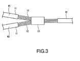
- Insulation sheaths 11 of electrical wires W1 and W2 are stripped at given intermediate parts in a longitudinal direction to expose core conductors 12.
- the exposed core conductors 12 are bonded by means of ultrasonic welding to form a spliced portion 13.
- the spliced portion 13 is inserted into a container 14 so that the spliced portion 13 is immersed in a watertight agent 16 filled in the container 16.
- a lid 15 is mounted on the container 16 to seal an interior of the container 16.
- a watertight structure 10 for the spliced portion 13 is formed.
- the container 14 is made of an injection molding product and, as shown in Figure 2A , is formed into a generally boat-like configuration that extends in a longitudinal direction X of the electrical wires W1 and W2.
- the container 14 includes a bottom wall 14a and opposed side walls 14d at a width direction Y perpendicular to the longitudinal direction X.
- the container 14 is opened at an upper part to define an open top 14g.
- the bottom wall 14a is provided with opposite side walls 14a-2 that incline upward from a middle part 14a-1 of the bottom wall 14a in the longitudinal direction X.
- the middle part 14a-1 of the bottom wall 14a is provided with a spliced portion positioning section 14c.
- the spliced portion positioning section 14c is defined by a space surrounded by a pair of projections 14e and a middle part 14a-1 that is deep and narrow between the projections 14e.
- Each projection 14e protrudes inward in a trapezoidal form so that middle parts of the projections 14e in the longitudinal direction X approach toward each other at upper and lower ends of the opposed side walls 14d. Since the projections 14e provided on the opposed side walls 14d have upper ends at the opposed side walls 14d, trapezoidal recesses are defined in lower parts of upper end frames 14d-1 at outer sides of the opposed side walls 14d.
- Each trapezoidal projection 14e is provided on an upper end with a trapezoidal upper surface portion 14e-1 contiguous with the upper end frame 14d-1 of the side wall 14d.
- Each trapezoidal upper surface portion 14e-1 is provided with a receiving aperture 14f that is opened toward the recessed space. The receiving aperture 14f serves to lock the lid 15.
- the spliced portion positioning section 14c is disposed between the pair of trapezoidal projections 14e to define a narrow space 14c-1 at a central part and gradually enlarging spaces 14c-2 at opposite sides.
- the spliced portion positioning section 14c is provided in opposed upper sides with lid receiving apertures 14f.
- the longitudinally opposite sides of the spliced portion positioning section 14c are contiguous with the space 14c-2 and include opposite side portions 14a-2 of the bottom wall 14a that become shallow gradually and insulation sheathed electrical wire containing portions 14h between the opposed side walls 14d.
- the lid 15 is also made of an injection molding product and is shaped so that the lid can be mounted downward onto the spliced portion positioning section 14c of the container 14. That is, as shown in Figure 2B , the lid 15 includes a central narrow flat plate-like portion 15a adapted to be fitted in the spliced portion positioning section 14c of the container 14, and wide flat plate-like portions 15b at opposite sides in the longitudinal direction.
- the narrow portion 15a is provided on opposite sides in a width direction with each guide wall 15c.
- the guide wall 15c is provided on an upper end with a locking piece 15d bent outward and downward, and the locking piece 15d is provided on a lower end with a locking pawl 15e.
- the locking pieces 15d on the lid 15 are inserted into the receiving apertures 14f in the upper side portions 14e-1 of the container 14 and the locking pawls 15e at lower ends of the locking pieces 15d engage with lower surfaces of the upper side portions 14e-1.
- the watertight agent 16 is made of an epoxy resin.
- the watertight agent is not limited to the epoxy resin and may be made of polypropylene, polyamide, or the like. Also, two-liquid mixed adhesive (urethane or the like) or one-liquid adhesive (silicone RTV or the like) may be used as the watertight agent 16.
- the electrical wires W1 and W2 are inserted through the open top 14g into the container 14, the spliced portion 13 of the electrical wires W1 and W2 and exposed core conductors 12 at the opposite ends of the spliced portion 13 are pushed into the deepest, narrow space 14c-1 in the spliced portion positioning section 13 of the container 14, and the electrical wires W1 and W2 covered with insulation sheaths 11 and contiguous with the opposite ends of the spliced portion 13 are inserted through gradually enlarging space 14c-2 into the electrical wire containing portions 14h.
- the electrical wire containing portions 14h become gradually shallow, the electrical wires W1 and W2 are inserted into the container 14 so that the spliced portion 13 is disposed at the lowest position in the container 14 and the opposite ends of the wires are gradually displaced upward.
- the watertight agent 16 is filled in the container 14.
- the spliced portion 13, exposed core conductors 12 at the opposite end of the spliced portion 13, and distal ends of the electrical wires W1 and W2 covered with insulation sheaths 11 at the opposite exposed core conductors 12 are immersed in the watertight agent 16.
- the lid 15 is mounted on the container 14, the guide walls 15c at the opposite sides of the lid 15 are pushed down along the inner surfaces of the projections 14e on the container 14, the spliced portion 13, exposed core conductors 12, and watertight agent 16 are pushed down into the narrow width portion 15a between the lower ends of the guide walls 15c.
- These operations enable the watertight agent 16 to be perfectly flowed into a space among the spliced portion 13, exposed core conductors 12, and bottom wall 14a of the container 14, thereby eliminating any clearance that is not filled with the watertight agent 16.
- the opposite wide width portions 15b of the lid 15 are fitted in the electrical wire containing portions 14h, push the watertight agent 16 and the electrical wires W1 and W2 accommodated in the electrical wire containing portions 14h and covered with the insulation sheaths 11, and cause the watertight agent 16 to be positively flowed into a space between the electrical wires W1 and W2, thereby eliminating any clearance that is not filled with the watertight agent 16.
- each of the electrical wire containing portions 14 is provided with the bottom wall that is gradually inclined upward to gradually form a shallow depth, when the wide width portions 15b of the lid 15 cover the portions 14h, the distal ends of the electrical wires W1 and W2 covered with the insulation sheaths 11 and inserted into the portions 14h can be immersed in a small amount of watertight agent 16.
- the lid 15 is mounted on the electrical wire containing portions 14h so that the watertight agent 16 is filled in the container 14 without causing any clearances, the lower parts of the locking pieces 15d of the lid 15 are inserted into the receiving apertures 14f in the container 14, the locking pawls 15e at the lower ends engage the lower surfaces of the upper side portions 14e-1, and the lid 15 is secured to the container 14.
- the lid 15 is secured to the container 14.
- the container 14 is heated at 70 °C (degrees in centigrade) to harden the watertight agent 16, and the spliced portion 13 of the electrical wires W1 and W2, exposed core conductors 12 at the opposite ends of the spliced portion 13, and the electrical wires W1 and W2 covered with the insulation sheaths 11 are embedded in the hardened watertight agent 16.
- the spliced portion 13 of the electrical wires W1 and W2 is constrained from moving in a width direction between the opposed projections 14e in the spliced portion positioning section 14c and from moving in a vertical direction between the container bottom wall 14a and the lid 15, thereby precisely holding and containing the spliced portion 13 in the container 14. Since the spliced positioning section 14c is arranged on the deepest part in the container 14, it is possible to surely embed the spliced portion 13 and opposite exposed core conductors 12 in the watertight agent 16.
- the lid 15 pushes the watertight agent 16, it is possible to fill the watertight agent 16 in the clearance among the spliced portion 13, exposed core conductors 12, distal ends of electrical wires W1 and W2 covered with the insulation sheaths 11 and contiguous with the exposed core conductors 12, thereby enhancing a waterproofing function. Since the lid 15 presses the watertight agent 16 and the container 14 is formed into the boar-like configuration, it is possible to surely embed the spliced portion 13 in even a small amount of the watertight agent.
- the container 14 and lid 15 are shareable in use, so long as the spliced portion 13 has a size adequate to be inserted into a space between the spliced portion positioning section 14c and the narrow portion 15a of the lid 15 regardless of the numbers and diameters of the electrical wires to be spliced. Further, since the container 14 is formed into the boat-like configuration, it is possible for the container to prevent the watertight agent 16 from being leaked outside.
Landscapes
- Processing Of Terminals (AREA)
- Connections Effected By Soldering, Adhesion, Or Permanent Deformation (AREA)
- Laying Of Electric Cables Or Lines Outside (AREA)
Abstract
Description
- This invention relates to a watertight structure for a spliced portion, and more particularly relates to a structure in which a watertight agent is surely filled around spliced portion on wire harnesses to be arranged in a motor vehicle so as to perform a waterproofing function.
- Before, in the case where a plurality of electrical wires in wire harnesses to be arranged in a motor vehicle are connected to one another, insulation sheaths of the electrical wires are stripped to expose core conductors, the exposed core conductors are connected to one another by means of welding, soldering, or crimping by crimping terminals to form a spliced portion. Since the core conductors or crimping terminals will be eroded if water adheres to the spliced portion, wire harnesses to be arranged in an engine compartment in a motor vehicle, which is a water-receiving area, have spliced portions with a waterproofing function.
- The present applicant has disclosed a waterproofing process in
JP HEI 7(1995)-184308 A Figures 5A and 5B show awatertight structure 1 for a spliced portion on electrical wires inPatent Document 1.Figure 5A is a perspective view of a prior art resin mold for producing a prior art watertight structure for a spliced portion.Figure 5B is a longitudinal section view of the prior art watertight structure for the spliced portion.
In thewatertight structure 1, core conductors a and b are exposed from electrical wires W1 and W2 constituting wire harnesses, a splicedportion 2 that is formed by crimping the exposed core conductors a and b by crimping terminals is inserted into aresin mold 3, and a watertight agent 4 is filled in theresin mold 3.
Theresin mold 3 is formed into a box-like configuration elongated longitudinally and having an open top. Abottom wall 3a of theresin mold 3 is provided on longitudinal opposite side ends withside walls 3b-1 and 3b-2 for receiving the electrical wires W1 and W2 and on opposite lateral sides withside walls 3c. Oneside wall 3b-1 is provided in an upper end with a single electricalwire threading groove 3d-1 that corresponds to a size of the electrical wire W1 while theother side wall 3b-2 is provided in an upper end with two electricalwire threading grooves 3d-2 and 3d-3 that correspond to sizes of the electrical wires W1 and W2. The sizes of the respective electricalwire threading grooves 3d-1 to 3d-3 are set to be dimensions in which the respective electrical wires W1 and W2 are fitted closely in the respective grooves. - Patent Document 1:
JP HEI 7(1995)-184308 A - Since the resin mold for waterproofing disclosed in
Patent Document 1 closely fits the electrical wires in the electrical wire threading grooves, it is necessary to prepare the electrical wire threading grooves that have the same sizes and numbers as those of the electrical wires. Consequently, there is a problem that various kinds of resin molds must be prepared in accordance with the sizes and numbers of the electrical wires to be spliced.
Although insulation sheaths of the electrical wires are held in the electrical wire threading grooves, the spliced portion is floated in the resin mold. There is also another problem that the spliced portion further floats upward in the resin mold and a resin is difficult to flow onto the upper part of the spliced portion, whereby a sufficient waterproofing function cannot be accomplished, if a resin is filled into the resin mold while the spliced portion is floated. - In view of the above problems, an object of the present invention is to provide a watertight structure for a spliced portion on electrical wires in which the container can be used regardless of sizes and numbers of the electrical wires to be spliced so long as the spliced portion on the electrical wires can be accommodated in a container, and a suitable amount of a watertight agent can perform a waterproofing function.
- In order to achieve the above object, a watertight structure for a spliced portion in accordance with the present invention includes a container that has an open top adapted to receive a spliced portion of electrical wires and that is elongated in a longitudinal direction of the electrical wires, and a lid to be mounted on the container. The container is provided with a bottom wall including a central flat portion at a deepest position in the container and upward inclined portions that extend from opposite sides of the central flat portion in a longitudinal direction. The central flat portion is provided with a spliced portion positioning section having a narrow width. The spliced portion positioning section is provided on opposite outer sides with receiving portions to be engaged with locking pieces projecting from opposite sides of the lid. The lid is provided on a middle part in the longitudinal direction with a narrow width portion adapted to be fitted in the spliced portion positioning section. Wide width portions at opposite sides of the narrow width portion in the longitudinal direction are formed into configurations adapted to be fitted in spaces at opposite sides of the spliced portion positioning section of the container in the longitudinal direction. The spliced portion of the electrical wires is fitted and held in the spliced portion positioning section in the container. The spliced portion is embedded in a watertight agent. The lid closes the embedded part to secure the spliced portion to the container.
- As described above, in the present invention, the electrical wires are disposed in the elongated container in the longitudinal direction. The spliced portion of the electrical wires is fitted and held in the spliced portion positioning section of the container and is embedded in the watertight agent to perform a waterproofing function. Consequently, it is possible to waterproof the spliced portion of the electrical wires regardless of sizes and numbers of the electrical wires to be spliced, so long as the spliced portion has a dimension to be contained in the spliced portion positioning section. Accordingly, it is not necessary to prepare various kinds of containers in accordance with the sizes and numbers of the electrical wires to be spliced.
Also, since the lid closes the embedded spliced portion, it is possible to prevent the spliced portion from being moved upward and to cause the watertight agent to be flowed above the spliced portion, thereby surely embedding the spliced portion in the watertight agent and effecting the waterproofing function.
In addition, since the spliced portion is not moved upward, it is possible to fill a space above the spliced portion with a small amount of the watertight agent. - In more detail, the container is formed into a boat-like configuration. The spliced portion positioning section is provided with a pair of opposed projections that protrude inward from opposed side walls in a width direction perpendicular to the longitudinal direction. Each of the projections is provided on a top with a receiving aperture. The lid is provided on opposite sides of the narrow width portion in the width direction with guide walls adapted to be arranged along inner surfaces of the projections of the container. Each of the guide walls is provided with a locking piece bent outward and downward from an upper end of each guide wall. Each locking piece is provided on a lower end with a locking pawl adapted to be inserted and fitted in each receiving aperture.
- According to the above construction, since a space between the opposed projections protruding inward from the opposed side walls of the container defines the spliced portion positioning section and the size of the spliced portion is formed in accordance with the size of the spliced portion positioning section, the spliced portion positioning section can hold the spliced portion.
Also, since the projections protrude from the opposed side walls of the container and the spliced portion positioning section is the narrow width, it is possible to reduce an amount of the watertight agent to be filled in the container.
Furthermore, since the locking pieces of the lid are engaged with the receiving apertures in the top of the projections, the lid can be disposed on the upper part of the spliced portion and the spliced portion is not moved upward by the lid during filling the watertight agent, thereby surely embedding the spliced portion in the watertight agent. - As describe above, according to the watertight structure for the spliced portion in accordance with the present invention, the electrical wires are disposed in the elongated container in the longitudinal direction. The spliced portion of the electrical wires is fitted and held in the spliced portion positioning section of the container and is embedded in the watertight agent to perform a water-tightening function. Consequently, it is possible to waterproof the spliced portion of the electrical wires regardless of sizes and numbers of the electrical wires to be spliced, so long as the spliced portion has a dimension sized to be contained in the spliced portion positioning section.
-
- [
Fig. 1] Figure 1 is a perspective view of a first embodiment of a watertight structure for a spliced portion in accordance with the present invention. - [
Fig. 2] Figure 2A is a perspective view of a container.Figure 2B is a perspective view of a lid. - [
Fig. 3] Figure 3 is a plan view of electrical wires, illustrating a spliced portion of the wires. - [
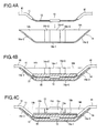
Fig. 4] Figures 4A to 4C are explanatory views of a watertight process of the present invention. - [
Fig. 5] Figure 5A is a perspective view of a prior art resin mold for producing a prior art watertight structure for a spliced portion.Figure 5B is a longitudinal section view of the prior art watertight structure for the spliced portion. -
- 10
- watertight structure for a spliced portion
- 13
- spliced portion
- 14
- container
- 14a
- bottom wall
- 14c
- spliced portion positioning section
- 14e
- projections
- 14f
- receiving aperture
- 15
- lid
- 15a
- narrow width portion
- 15b
- wide width portion
- 15c
- guide walls
- 15d
- locking pieces
- 15e
- locking pawls
- 16
- watertight agent
- W1, W2
- electrical wires
- Referring now to the drawings, embodiments of a watertight structure for a spliced portion in accordance with the present invention will be described below.
Figures 1 through 4C show a first embodiment of the watertight structure for the spliced portion of the present invention.
Insulation sheaths 11 of electrical wires W1 and W2 are stripped at given intermediate parts in a longitudinal direction to exposecore conductors 12. The exposedcore conductors 12 are bonded by means of ultrasonic welding to form a splicedportion 13. The splicedportion 13 is inserted into acontainer 14 so that the splicedportion 13 is immersed in awatertight agent 16 filled in thecontainer 16. Then, alid 15 is mounted on thecontainer 16 to seal an interior of thecontainer 16. Thus, awatertight structure 10 for the splicedportion 13 is formed. - The
container 14 is made of an injection molding product and, as shown inFigure 2A , is formed into a generally boat-like configuration that extends in a longitudinal direction X of the electrical wires W1 and W2. Thecontainer 14 includes abottom wall 14a andopposed side walls 14d at a width direction Y perpendicular to the longitudinal direction X. Thecontainer 14 is opened at an upper part to define an open top 14g. Thebottom wall 14a is provided withopposite side walls 14a-2 that incline upward from amiddle part 14a-1 of thebottom wall 14a in the longitudinal direction X. Themiddle part 14a-1 of thebottom wall 14a is provided with a splicedportion positioning section 14c. - The spliced
portion positioning section 14c is defined by a space surrounded by a pair ofprojections 14e and amiddle part 14a-1 that is deep and narrow between theprojections 14e. Eachprojection 14e protrudes inward in a trapezoidal form so that middle parts of theprojections 14e in the longitudinal direction X approach toward each other at upper and lower ends of theopposed side walls 14d.
Since theprojections 14e provided on theopposed side walls 14d have upper ends at theopposed side walls 14d, trapezoidal recesses are defined in lower parts of upper end frames 14d-1 at outer sides of theopposed side walls 14d. - Each
trapezoidal projection 14e is provided on an upper end with a trapezoidalupper surface portion 14e-1 contiguous with theupper end frame 14d-1 of theside wall 14d. Each trapezoidalupper surface portion 14e-1 is provided with a receivingaperture 14f that is opened toward the recessed space. The receivingaperture 14f serves to lock thelid 15. - Thus, the spliced
portion positioning section 14c is disposed between the pair oftrapezoidal projections 14e to define anarrow space 14c-1 at a central part and gradually enlargingspaces 14c-2 at opposite sides. The splicedportion positioning section 14c is provided in opposed upper sides withlid receiving apertures 14f. The longitudinally opposite sides of the splicedportion positioning section 14c are contiguous with thespace 14c-2 and includeopposite side portions 14a-2 of thebottom wall 14a that become shallow gradually and insulation sheathed electricalwire containing portions 14h between theopposed side walls 14d. - The
lid 15 is also made of an injection molding product and is shaped so that the lid can be mounted downward onto the splicedportion positioning section 14c of thecontainer 14.
That is, as shown inFigure 2B , thelid 15 includes a central narrow flat plate-like portion 15a adapted to be fitted in the splicedportion positioning section 14c of thecontainer 14, and wide flat plate-like portions 15b at opposite sides in the longitudinal direction.
Thenarrow portion 15a is provided on opposite sides in a width direction with eachguide wall 15c. Theguide wall 15c is provided on an upper end with alocking piece 15d bent outward and downward, and thelocking piece 15d is provided on a lower end with a lockingpawl 15e. - When the
guide walls 15c of thelid 15 are slid along inner surfaces of theprojections 14e on thecontainer 14 and are fitted into the splicedportion positioning section 14c, the lockingpieces 15d on thelid 15 are inserted into the receivingapertures 14f in theupper side portions 14e-1 of thecontainer 14 and the lockingpawls 15e at lower ends of the lockingpieces 15d engage with lower surfaces of theupper side portions 14e-1. - The
watertight agent 16 is made of an epoxy resin.
The watertight agent is not limited to the epoxy resin and may be made of polypropylene, polyamide, or the like. Also, two-liquid mixed adhesive (urethane or the like) or one-liquid adhesive (silicone RTV or the like) may be used as thewatertight agent 16. - Next, a process for waterproofing the spliced
portion 13 will be described below.
Firstly, as shown inFigure 4A , the electrical wires W1 and W2 are inserted through the open top 14g into thecontainer 14, the splicedportion 13 of the electrical wires W1 and W2 and exposedcore conductors 12 at the opposite ends of the splicedportion 13 are pushed into the deepest,narrow space 14c-1 in the splicedportion positioning section 13 of thecontainer 14, and the electrical wires W1 and W2 covered withinsulation sheaths 11 and contiguous with the opposite ends of the splicedportion 13 are inserted through gradually enlargingspace 14c-2 into the electricalwire containing portions 14h. At this time, since the electricalwire containing portions 14h become gradually shallow, the electrical wires W1 and W2 are inserted into thecontainer 14 so that the splicedportion 13 is disposed at the lowest position in thecontainer 14 and the opposite ends of the wires are gradually displaced upward. - Secondly, as shown in
Figure 4B , thewatertight agent 16 is filled in thecontainer 14. The splicedportion 13, exposedcore conductors 12 at the opposite end of the splicedportion 13, and distal ends of the electrical wires W1 and W2 covered withinsulation sheaths 11 at the opposite exposedcore conductors 12 are immersed in thewatertight agent 16. - Thirdly, as shown in
Figure 4C , thelid 15 is mounted on thecontainer 14, theguide walls 15c at the opposite sides of thelid 15 are pushed down along the inner surfaces of theprojections 14e on thecontainer 14, the splicedportion 13, exposedcore conductors 12, andwatertight agent 16 are pushed down into thenarrow width portion 15a between the lower ends of theguide walls 15c. These operations enable thewatertight agent 16 to be perfectly flowed into a space among the splicedportion 13, exposedcore conductors 12, andbottom wall 14a of thecontainer 14, thereby eliminating any clearance that is not filled with thewatertight agent 16.
Similarly, the oppositewide width portions 15b of thelid 15 are fitted in the electricalwire containing portions 14h, push thewatertight agent 16 and the electrical wires W1 and W2 accommodated in the electricalwire containing portions 14h and covered with theinsulation sheaths 11, and cause thewatertight agent 16 to be positively flowed into a space between the electrical wires W1 and W2, thereby eliminating any clearance that is not filled with thewatertight agent 16.
Since each of the electricalwire containing portions 14 is provided with the bottom wall that is gradually inclined upward to gradually form a shallow depth, when thewide width portions 15b of thelid 15 cover theportions 14h, the distal ends of the electrical wires W1 and W2 covered with theinsulation sheaths 11 and inserted into theportions 14h can be immersed in a small amount ofwatertight agent 16. - As described above, the
lid 15 is mounted on the electricalwire containing portions 14h so that thewatertight agent 16 is filled in thecontainer 14 without causing any clearances, the lower parts of the lockingpieces 15d of thelid 15 are inserted into the receivingapertures 14f in thecontainer 14, the lockingpawls 15e at the lower ends engage the lower surfaces of theupper side portions 14e-1, and thelid 15 is secured to thecontainer 14. Thus, it is possible to prevent the pushedlid 15 from being moved upward. - Under this condition, the
container 14 is heated at 70 °C (degrees in centigrade) to harden thewatertight agent 16, and the splicedportion 13 of the electrical wires W1 and W2, exposedcore conductors 12 at the opposite ends of the splicedportion 13, and the electrical wires W1 and W2 covered with theinsulation sheaths 11 are embedded in the hardenedwatertight agent 16. - In the above watertight structure for the spliced portion in accordance with the present invention, the spliced
portion 13 of the electrical wires W1 and W2 is constrained from moving in a width direction between theopposed projections 14e in the splicedportion positioning section 14c and from moving in a vertical direction between thecontainer bottom wall 14a and thelid 15, thereby precisely holding and containing the splicedportion 13 in thecontainer 14. Since the splicedpositioning section 14c is arranged on the deepest part in thecontainer 14, it is possible to surely embed the splicedportion 13 and opposite exposedcore conductors 12 in thewatertight agent 16.
Furthermore, since thelid 15 pushes thewatertight agent 16, it is possible to fill thewatertight agent 16 in the clearance among the splicedportion 13, exposedcore conductors 12, distal ends of electrical wires W1 and W2 covered with theinsulation sheaths 11 and contiguous with the exposedcore conductors 12, thereby enhancing a waterproofing function.
Since thelid 15 presses thewatertight agent 16 and thecontainer 14 is formed into the boar-like configuration, it is possible to surely embed the splicedportion 13 in even a small amount of the watertight agent. - The
container 14 andlid 15 are shareable in use, so long as the splicedportion 13 has a size adequate to be inserted into a space between the splicedportion positioning section 14c and thenarrow portion 15a of thelid 15 regardless of the numbers and diameters of the electrical wires to be spliced. Further, since thecontainer 14 is formed into the boat-like configuration, it is possible for the container to prevent thewatertight agent 16 from being leaked outside.
Claims (2)
- A watertight structure for a spliced portion including a container that has an open top adapted to receive a spliced portion of electrical wires and that is elongated in a longitudinal direction of the electrical wires, and a lid to be mounted on said container;
wherein said container is provided with a bottom wall including a central flat portion at a deepest position in said container and upward inclined portions that extend from opposite sides of said central flat portion in a longitudinal direction, said central flat portion is provided with a spliced portion positioning section having a narrow width, said spliced portion positioning section is provided on opposite outer sides with receiving portions to be engaged with locking pieces projecting from opposite sides of said lid;
wherein said lid is provided on a middle part in the longitudinal direction with a narrow width portion adapted to be fitted in said spliced portion positioning section, wide width portions at opposite sides of said narrow width portion in the longitudinal direction are formed into configurations adapted to be fitted in spaces at opposite sides of said spliced portion positioning section of said container in the longitudinal direction; and
wherein said spliced portion of said electrical wires is fitted and held in said spliced portion positioning section in said container, said spliced portion is embedded in a watertight agent, and said lid closes the embedded part to secure said spliced portion to said container. - A watertight structure for a spliced portion according to Claim 1, wherein said container is formed into a boat-like configuration, said spliced portion positioning section is provided with a pair of opposed projections that protrude inward from opposed side walls in a width direction perpendicular to the longitudinal direction, and each of said projections is provided on a top with a receiving aperture; and
wherein said lid is provided on opposite sides of said narrow width portion in the width direction with guide walls adapted to be arranged along inner surfaces of said projections of said container, each of said guide walls is provided with a locking piece bent outward and downward from an upper end of each guide wall, and each of said locking pieces is provided on a lower end with a locking pawl adapted to be inserted and fitted in each of said receiving apertures.
Applications Claiming Priority (2)
| Application Number | Priority Date | Filing Date | Title |
|---|---|---|---|
| JP2006356029A JP4525674B2 (en) | 2006-12-28 | 2006-12-28 | Water stop structure of splice |
| PCT/JP2007/061707 WO2008081612A1 (en) | 2006-12-28 | 2007-06-11 | Water stop structure at splice portion |
Publications (2)
| Publication Number | Publication Date |
|---|---|
| EP2101374A1 true EP2101374A1 (en) | 2009-09-16 |
| EP2101374A4 EP2101374A4 (en) | 2010-12-29 |
Family
ID=39588300
Family Applications (1)
| Application Number | Title | Priority Date | Filing Date |
|---|---|---|---|
| EP07744999A Withdrawn EP2101374A4 (en) | 2006-12-28 | 2007-06-11 | Water stop structure at splice portion |
Country Status (4)
| Country | Link |
|---|---|
| US (1) | US8076579B2 (en) |
| EP (1) | EP2101374A4 (en) |
| JP (1) | JP4525674B2 (en) |
| WO (1) | WO2008081612A1 (en) |
Families Citing this family (4)
| Publication number | Priority date | Publication date | Assignee | Title |
|---|---|---|---|---|
| DE102010018858B4 (en) * | 2010-04-30 | 2013-01-03 | Few Fahrzeugelektrikwerk Gmbh & Co. Kg | Contacting and connection arrangement consisting of foil conductors introduced in a housing |
| ITVI20120060A1 (en) | 2012-03-19 | 2013-09-20 | St Microelectronics Srl | ELECTRONIC SYSTEM HAVING INCREASED CONNECTION THROUGH THE USE OF HORIZONTAL AND VERTICAL COMMUNICATION CHANNELS |
| JP6172127B2 (en) * | 2014-11-28 | 2017-08-02 | 株式会社オートネットワーク技術研究所 | Wire Harness |
| CN105071064B (en) * | 2015-08-06 | 2017-08-11 | 大唐岩滩水力发电有限责任公司 | A kind of waterproof wiring protecting box flooded |
Family Cites Families (14)
| Publication number | Priority date | Publication date | Assignee | Title |
|---|---|---|---|---|
| CA995315A (en) * | 1975-08-21 | 1976-08-17 | Slater Steel Industries Limited | Cable splice housing |
| US4283592A (en) * | 1979-08-23 | 1981-08-11 | Akzona Incorporated | Filled electrical splice case |
| JPS6041787Y2 (en) * | 1981-07-30 | 1985-12-19 | ミサワホ−ム株式会社 | Structure of wire connection part |
| JPS5822042A (en) | 1981-07-31 | 1983-02-09 | アロカ株式会社 | Ultrasonic diagnostic apparatus |
| JP2650547B2 (en) * | 1992-01-09 | 1997-09-03 | 住友電装株式会社 | Method of forming waterproof structure and waterproof structure formed by the method |
| JPH07184308A (en) | 1993-12-24 | 1995-07-21 | Sumitomo Wiring Syst Ltd | Wire harness splicing method and splice structure |
| JP3152052B2 (en) * | 1994-03-04 | 2001-04-03 | 住友電装株式会社 | Splice method and structure of wire harness |
| JP3211546B2 (en) * | 1994-03-17 | 2001-09-25 | 住友電装株式会社 | Splice method and structure of wire harness |
| JP2002170432A (en) | 2000-11-29 | 2002-06-14 | Sumitomo Wiring Syst Ltd | Wire harness waterproof structure |
| JP4433953B2 (en) | 2004-09-09 | 2010-03-17 | 住友電装株式会社 | Waterproofing method and waterproofing structure of terminal splice part |
| US7049520B1 (en) * | 2005-03-15 | 2006-05-23 | Hubbell Incorporated | Connector for splicing cables |
| US7402751B2 (en) * | 2005-10-03 | 2008-07-22 | International Business Machines Corporation | Electrical bifurcated splice |
| US7282644B1 (en) * | 2006-01-17 | 2007-10-16 | Verizon Services Corp. | Aerial cable splice closure |
| US7435144B2 (en) * | 2007-01-22 | 2008-10-14 | Fci Americas Technology, Inc. | Electrical splice connector |
-
2006
- 2006-12-28 JP JP2006356029A patent/JP4525674B2/en not_active Expired - Fee Related
-
2007
- 2007-06-11 WO PCT/JP2007/061707 patent/WO2008081612A1/en not_active Ceased
- 2007-06-11 EP EP07744999A patent/EP2101374A4/en not_active Withdrawn
- 2007-06-11 US US12/520,921 patent/US8076579B2/en not_active Expired - Fee Related
Also Published As
| Publication number | Publication date |
|---|---|
| US20100018767A1 (en) | 2010-01-28 |
| WO2008081612A1 (en) | 2008-07-10 |
| JP2008166176A (en) | 2008-07-17 |
| EP2101374A4 (en) | 2010-12-29 |
| US8076579B2 (en) | 2011-12-13 |
| JP4525674B2 (en) | 2010-08-18 |
Similar Documents
| Publication | Publication Date | Title |
|---|---|---|
| EP2278594B1 (en) | Water stop structure for wire harness and method of forming water stop section | |
| CN105284007B (en) | The end structure of covered electric cable | |
| EP1635423B1 (en) | Method for waterproofing a terminal splice | |
| CN100553057C (en) | Connector | |
| JP5242112B2 (en) | Flexible flat harness, method for manufacturing the same, and power supply device for slide door | |
| EP0499533A2 (en) | Connector and method for sealed pass-through of insulated electrical conductors | |
| US9997857B2 (en) | Plug bridge, and method for producing a plug | |
| US8076579B2 (en) | Watertight structure for spliced portion | |
| US8246369B2 (en) | Waterproof device and a waterproof device producing method | |
| US10355395B2 (en) | Wire with terminal | |
| CN108292834B (en) | Cable holding structure | |
| EP1988606A1 (en) | Waterproof structure for connector housing | |
| JP5875868B2 (en) | Component housing for components that are substantially electrical components | |
| US20050003708A1 (en) | Waterproof connector | |
| JP2006228683A (en) | Waterproof connector | |
| US8379395B2 (en) | Electrical component | |
| CN103377840A (en) | Water-proofing electronic component | |
| JP2011065921A (en) | Shield wire having water cut-off section and method for forming water cut-off section of shield wire | |
| JP2000082508A (en) | Water stop terminal | |
| JP2004349071A (en) | Waterproof connector | |
| JP3017614B2 (en) | Derivation structure of lead wire from inside liquid container | |
| JP2007141517A (en) | Waterproofing method for wire harness | |
| JP2010068613A (en) | Wiring harness | |
| JP4297335B2 (en) | Lamp and flat cable connector and connection structure | |
| JP2000322940A (en) | Water stop structure inside electric wires |
Legal Events
| Date | Code | Title | Description |
|---|---|---|---|
| PUAI | Public reference made under article 153(3) epc to a published international application that has entered the european phase |
Free format text: ORIGINAL CODE: 0009012 |
|
| 17P | Request for examination filed |
Effective date: 20090625 |
|
| AK | Designated contracting states |
Kind code of ref document: A1 Designated state(s): AT BE BG CH CY CZ DE DK EE ES FI FR GB GR HU IE IS IT LI LT LU LV MC MT NL PL PT RO SE SI SK TR |
|
| DAX | Request for extension of the european patent (deleted) | ||
| A4 | Supplementary search report drawn up and despatched |
Effective date: 20101201 |
|
| GRAP | Despatch of communication of intention to grant a patent |
Free format text: ORIGINAL CODE: EPIDOSNIGR1 |
|
| RIC1 | Information provided on ipc code assigned before grant |
Ipc: H02G 1/14 20060101ALI20121130BHEP Ipc: H01R 43/00 20060101ALI20121130BHEP Ipc: H01R 4/70 20060101AFI20121130BHEP Ipc: H02G 15/113 20060101ALI20121130BHEP Ipc: H02G 15/013 20060101ALI20121130BHEP |
|
| STAA | Information on the status of an ep patent application or granted ep patent |
Free format text: STATUS: THE APPLICATION IS DEEMED TO BE WITHDRAWN |
|
| 18D | Application deemed to be withdrawn |
Effective date: 20130515 |