EP2101373A2 - Compression connector with tap port configured to engage multiple sized tap wires in a single tap port - Google Patents
Compression connector with tap port configured to engage multiple sized tap wires in a single tap port Download PDFInfo
- Publication number
- EP2101373A2 EP2101373A2 EP09250675A EP09250675A EP2101373A2 EP 2101373 A2 EP2101373 A2 EP 2101373A2 EP 09250675 A EP09250675 A EP 09250675A EP 09250675 A EP09250675 A EP 09250675A EP 2101373 A2 EP2101373 A2 EP 2101373A2
- Authority
- EP
- European Patent Office
- Prior art keywords
- tap wire
- tap
- compression connector
- body portion
- nest
- Prior art date
- Legal status (The legal status is an assumption and is not a legal conclusion. Google has not performed a legal analysis and makes no representation as to the accuracy of the status listed.)
- Granted
Links
- 230000006835 compression Effects 0.000 title claims abstract description 75
- 238000007906 compression Methods 0.000 title claims abstract description 75
- 238000002788 crimping Methods 0.000 claims abstract description 28
- 230000014759 maintenance of location Effects 0.000 claims description 9
- 238000003780 insertion Methods 0.000 abstract 1
- 230000037431 insertion Effects 0.000 abstract 1
- 238000004519 manufacturing process Methods 0.000 description 3
- RYGMFSIKBFXOCR-UHFFFAOYSA-N Copper Chemical compound [Cu] RYGMFSIKBFXOCR-UHFFFAOYSA-N 0.000 description 2
- 239000004020 conductor Substances 0.000 description 2
- 229910052802 copper Inorganic materials 0.000 description 2
- 239000010949 copper Substances 0.000 description 2
- 238000005452 bending Methods 0.000 description 1
- 238000009434 installation Methods 0.000 description 1
Images





Classifications
-
- H—ELECTRICITY
- H01—ELECTRIC ELEMENTS
- H01R—ELECTRICALLY-CONDUCTIVE CONNECTIONS; STRUCTURAL ASSOCIATIONS OF A PLURALITY OF MUTUALLY-INSULATED ELECTRICAL CONNECTING ELEMENTS; COUPLING DEVICES; CURRENT COLLECTORS
- H01R4/00—Electrically-conductive connections between two or more conductive members in direct contact, i.e. touching one another; Means for effecting or maintaining such contact; Electrically-conductive connections having two or more spaced connecting locations for conductors and using contact members penetrating insulation
- H01R4/10—Electrically-conductive connections between two or more conductive members in direct contact, i.e. touching one another; Means for effecting or maintaining such contact; Electrically-conductive connections having two or more spaced connecting locations for conductors and using contact members penetrating insulation effected solely by twisting, wrapping, bending, crimping, or other permanent deformation
- H01R4/18—Electrically-conductive connections between two or more conductive members in direct contact, i.e. touching one another; Means for effecting or maintaining such contact; Electrically-conductive connections having two or more spaced connecting locations for conductors and using contact members penetrating insulation effected solely by twisting, wrapping, bending, crimping, or other permanent deformation by crimping
- H01R4/183—Electrically-conductive connections between two or more conductive members in direct contact, i.e. touching one another; Means for effecting or maintaining such contact; Electrically-conductive connections having two or more spaced connecting locations for conductors and using contact members penetrating insulation effected solely by twisting, wrapping, bending, crimping, or other permanent deformation by crimping for cylindrical elongated bodies, e.g. cables having circular cross-section
- H01R4/186—Electrically-conductive connections between two or more conductive members in direct contact, i.e. touching one another; Means for effecting or maintaining such contact; Electrically-conductive connections having two or more spaced connecting locations for conductors and using contact members penetrating insulation effected solely by twisting, wrapping, bending, crimping, or other permanent deformation by crimping for cylindrical elongated bodies, e.g. cables having circular cross-section using a body comprising a plurality of cable-accommodating recesses or bores
-
- H—ELECTRICITY
- H01—ELECTRIC ELEMENTS
- H01R—ELECTRICALLY-CONDUCTIVE CONNECTIONS; STRUCTURAL ASSOCIATIONS OF A PLURALITY OF MUTUALLY-INSULATED ELECTRICAL CONNECTING ELEMENTS; COUPLING DEVICES; CURRENT COLLECTORS
- H01R9/00—Structural associations of a plurality of mutually-insulated electrical connecting elements, e.g. terminal strips or terminal blocks; Terminals or binding posts mounted upon a base or in a case; Bases therefor
- H01R9/03—Connectors arranged to contact a plurality of the conductors of a multiconductor cable, e.g. tapping connections
Definitions
- the present invention is directed to a compression connector and, more particularly, to a compression connector having a single tap wire port configuration that can accommodate several sizes of tap wires in one of a plurality of nests, each nest communicating with the single tap wire port formed in the connector.
- compression connectors can be found in the following U.S. Pat. Nos. 5,036,164 ; 5,200,576 ; 6,452,103 ; 6,486,403 ; 6,846,989 ; 7,026,552 ; 7,053,307 and 7,183,489 .
- none of these compression connectors have a body portion with a single opening forming a tap wire input port entrance, and a plurality of nests formed in the body portion, with each nest communicating with the single opening and adapted to receive the tap wire depending on the size of the tap wire.
- the previously disclosed compression connectors adapted to connect tap wires of varying sizes to a main line wire are relatively difficult to manufacture.
- a compression connector for securing at least one tap wire to a main line wire has a body portion with a first hook and first ramp extending from the body portion to form a first opening defining an entrance to a main wire port.
- the body portion also includes a second hook and a second ramp extending from the body portion to form a second opening defining an entrance to a tap wire port.
- At least one nest is formed in the tap wire port, each nest sized to receive a tap wire of varying size to facilitate crimping of the tap wire with a high degree of force.
- the tap wire port is configured to receive and accommodate any size of tap wire in a given range, whereby gradually larger sized wires can be crimped in the tap wire port as the space between the upper and lower surfaces forming the tap wire port increases in a direction toward the tap wire port entrance.
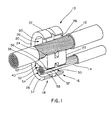
- FIG. 1 is a front perspective view of a compression connector according to a first embodiment of the present invention, shown in position around a main line wire and a tap wire prior to crimping;
- FIG. 2 is a front perspective view of the compression connector of FIG. 1 , shown after being crimped around the main line wire and the tap wire;
- FIG. 3 is a front perspective view of the compression connector of FIG. 1 ;
- FIG. 4 is a rear perspective view of the compression connector of FIG. 1 ;
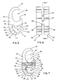
- FIG. 5 is a left side view of the compression connector of FIG. 1 ;
- FIG. 6 is a front view of the compression connector of FIG. 1 ;
- FIG. 7 is a cross-sectional view of the compression connector of FIG. 1 , taken along line 7-7 of FIG. 6 , and showing in phantom how a tap wire of different sizes would engage the appropriate nest of the tap wire port;
- FIG. 8 is a schematic side view of the compression connector of FIG. 1 after crimping by a pair of symmetrical crimping jaws, and illustrating the connection of a tap wire at the smaller end of the range of tap wire sizes with which the present invention is used;
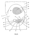
- FIG. 9 is a schematic side view of the compression connector of FIG. 1 after crimping by a pair of symmetrical crimping jaws, and illustrating the connection of a tap wire at the larger end of the range of tap wire sizes with which the present invention is used;
- FIG. 10 is a front perspective view of a compression connector according to a second embodiment of the present invention.
- FIG. 11 is a rear perspective view of the compression connector of FIG. 10 ;
- FIG. 12 is a front view of the compression connector of FIG. 10 ;
- FIG. 13 is a section view of the compression connector of FIG. 10 , taken along line 13-13 of FIG. 12 ;
- FIG. 14 is a front perspective view of a compression connector according to a third embodiment of the present invention.
- FIG. 15 is a rear perspective view of the compression connector of FIG. 14 ;
- FIG. 16 is a front view of the compression connector of FIG. 14 ;
- FIG. 17 is a section view of the compression connector of FIG. 14 , taken along line 17-17 of FIG. 16 .
- FIGS. 1-9 illustrate a first embodiment of the compression connector
- FIGS. 10-13 illustrate a modified embodiment of the compression connector
- FIGS. 14-17 illustrate a further embodiment of the compression connector.
- FIG. 1 shows a compression connector 10 prior to crimping and being secured around main line wire 12 and tap wire 14.
- compression connector 10 is a one piece member made of electrically conductive material, such as copper. However, it is likewise contemplated that compression connector 10 may be made of any suitable conductive materials or elements that will withstand a crimping operation.
- FIG. 2 illustrates compression connector 10 in its crimped position physically and electrically securing tap wire 14 to main line wire 12.
- compression connector 10 comprises a first section 16 and a second section 18.
- first section 16 and section 18 are identical, and each section includes a first body portion 20 having a hook 22, and a ramp 24 extending from the hook to form a main wire port 26 in which main line wires 12 can be placed.
- First section 16 and second section 18 are connected by a central body portion 27, as seen in FIG. 6 .
- hook 22 is C shaped.
- First section 16 and second section 18 each have a first end wall 28 forming part of body portion 20.
- Tap wire port 30 is adjacent each end wall 28 and, and retention tabs 32 extend from body portion 20.
- Tap wire port 30 can accommodate tap wires 14 of varying size, and provides a single entrance or opening 31 through which a tap wire 14 of any size within a given range can be readily inserted into tap wire port 30.
- tap wire port 30 is defined by an upper surface 34 and a lower surface 36.
- Lower surface 36 forms part of lower hook member 37.
- Surfaces 34 and 36 meet at a curved junction 38 opposite entrance 31 to form a first nest 40 to receive and accommodate a small diameter tap wire 14, as will be explained.
- Upper surface 34 also comprises a second curved portion 42, and the lower surface 36 also comprises a second curved portion 44.
- a portion 46 of upper surface 34 extends between nest 40 and second curved portion 42, and a portion 48 of lower surface 36 extends between nest 40 and raised portion 50 on surface 36.
- the space in tap wire port 30 between portion 46 of upper surface 34 and portion 48 of lower surface 36 defines a second nest 52 for accommodating a tap wire 14 in a certain range of sizes larger than the tap wires that are accommodated in first nest 40.
- second curved portion 42 of upper surface 34 and second curved portion 44 of lower surface 36 combine to form a third nest 54 for receiving and accommodating a tap wire having a diameter too large to be received in first nest 40 or second nest 52.
- the upper surface 34 of tap wire port 30 also comprises a curved portion 56 ending at retention tab 32.
- Lower surface 36 of tap wire port 30 includes a curved portion 56 leading to the tip 58 of body portion 20. Curved portion 56 is configured to receive tip 58 upon crimping, as will be explained. It is apparent in FIG. 7 that the space between retention tab 32 and tip 58 defines the single entrance or opening 31 into tap wire port 30.
- Body portion 20 also includes hinge-like portions 60 and 62 to provide bending of hook 22 and lower hook member, respectively.
- compression connector 10 includes two slots, 64, 66 extending between the first section 16 and the second section 18. Slots 64, 66 provide a space to loop a cable tie (not shown) to secure main line wire 12 and tap wire 14 to compression connector 10 before crimping, as disclosed in commonly assigned U.S. Patent No. 6,818,830 , the disclosure of which is incorporated by reference in its entirety. Although FIGS. 1-17 show compression connector 10 having slots 64, 66, it is similarly contemplated that compression connector 10 may not have any slots.
- FIGS. 10-13 A second embodiment of the present invention is illustrated in FIGS. 10-13 .
- This embodiment is similar to the embodiment of FIGS. 1-9 and like elements are identified with like numerals.
- the size of second curved portion 42a of upper surface 34 in FIG. 13 is smaller than second curved portion 42 in FIG. 7 .
- curved portion 56a of upper surface 34 in FIG. 13 is longer than curved portion 56 in FIG. 7 .
- the differences between these two embodiments illustrate how the configuration of tap wire port 30 can be modified to allow the tap wire port to receive and accommodate tap wires in various size ranges.
- first nest 40, second nest 52, and third nests 54, 54a ( FIGS. 7, 13 ) determine the range of tap wire sizes that can be accommodated by compression connector 10.
- FIGS. 14-17 A third embodiment of the present invention is illustrated in FIGS. 14-17 , where like elements are identified with like numerals.
- This embodiment of the compression connector 10 is similar to that disclosed in FIGS. 1-9 , with the exception that retention tab 32 is deleted at the entrance 31 to tap wire port 30.
- curved portion 56b of upper surface 34 is directed upward and away from second curved portion 42, as seen in FIG. 17 .
- the structure of the embodiment of FIGS. 14-17 is the same as the embodiment of FIGS. 1-9 .
- C-shaped compression connector 10 allows partial hands free installation since hook 22 can be hung around main line wire 12 while tap wire 14 of varying sizes is inserted through single opening or entrance 31 into tap wire port 30. If tap wire 14 is one of the smaller sizes in the size range for which compression connector 10 is configured to accept, tap wire 14 will lodge in first nest 40 defined by curved junction 38. Likewise, if tap wire 14 is a mid-range size, the tap wire will lodge in second nest 52 defined by portion 46 of upper surface 34 and by portion 48 of lower surface 36 of tap wire port 30. If tap wire 14 is a larger sized wire, the tap wire will lodge in third nest 54 defined by second curved portion 42 of upper surface 34 and by second curved portion 44 of lower surface 36 of tap wire port 30.
- any size tap wire 14 within the range of wire sizes with which compression connector 10 is configured to function is installed in tap wire port 30 through the single entrance 31.
- No additional entrances or openings are necessary in body portion 20 to accommodate tap wires of varying dimensions, thus maintaining the integrity and strength of the body portion 20 for its crimping function, as will be explained.
- Tap wire 14 is moved into tap port 30 until it can move in no further. At this point, the tap wire is lodged in its appropriate nest 40, 52 or 54.
- compression connector 10 is crimped around wires 12 and 14 using a crimping tool (not shown), such as Panduit® CT-2940 crimp tool, fitted with a pair of crimp dies 68, 70, as illustrated in FIGS. 8 and 9 , such as Panduit® CD-940H-250 crimp dies.
- a crimping tool such as Panduit® CT-2940 crimp tool
- a pair of crimp dies 68, 70 as illustrated in FIGS. 8 and 9 , such as Panduit® CD-940H-250 crimp dies.
- the outer radius of hook 22 and of first end wall 28 are smaller than the inner radius of crimping dies 68 and 70, and, thus, two die contact points are created.
- FIGS. 8 and 9 illustrate the location of a smaller range tap wire 14 lodged in nest 40 of tap wire port 30 after the tap wire has been crimped tightly between portion 46 of upper surface 34 and portion 48 of lower surface 36.
- Tip 58 of body portion 20 is crimped inside of curved portion 56 of body portion 20, and tip portion 58 is partially held in place by retention tab 32.
- FIG. 9 discloses the compression connector 10, after crimping, with a larger sized tap wire 14, compared to FIG. 8 , electrically and physically connected to main line wire 12. Tap wire 14 was too large to lodge in nest 40 or nest 52, and prior to crimping became lodged in nest 54. Upon crimping, tap wire 14 in FIG. 9 is crimped tightly between second curved portion 42 of upper surface 34 and second curved portion 44 of lower surface 36 of tap wire port 30. Tip 58 of body portion 20 is partially held in place in curved portion 56 by retention tab 32.
- tap wire 14 sized between the dimensions of tap wires shown in FIGS. 8 and 9 , that tap wire, subsequent to crimping would be tightly crimped in second nest 52 ( FIG. 7 ) between portion 46 of upper surface 34 and portion 48 of lower surface 36 of tap wire port 30.
- the compression connector embodiment shown in FIGS. 10-13 is identical to the embodiment shown in FIGS. 1-9 , with the exception that third nest 54a in FIG. 13 is smaller than second nest 54 in FIG. 7 , and curved portion 56a in FIG. 13 is configured differently than curved portion 56 in FIG. 7 .
- the embodiment of FIGS. 10-13 shows that where different ranges of tap wire sizes are to be electrically and physically attached to a main line wire, the configuration of the several nests in tap wire port 30 can be modified to accept the largest to the smallest sized tap wire in the selected range.
- the crimping operation of the compression connector embodiment of FIGS. 10-13 is the same as described above regarding FIGS. 1-9 .
- FIGS. 14-17 The embodiment of the invention shown in FIGS. 14-17 is also substantially similar to the compression connector 10 illustrated in FIGS. 1-9 , with the exception that retention tab 32 ( FIG. 7 ) is removed from this embodiment.
- tip 58 When the embodiment of FIG. 17 is crimped, tip 58 abuts curved surface 56b, crimping tap wire 14 between upper surface 34 and lower surface 36 of tap wire port 30. Due to the inherent capability of copper to remain in the crimped position without any meaningful spring-back, lower surface 36 of tap wire port 30 remains tightly engaged against any tap wire placed in tap wire port 30 through the single entrance 31.
- the disclosed invention provides a compression connector having the ability to receive and accommodate different sized tap wires within a specified range of wire sizes in a tap wire port having a single opening.
- the single opening provides a compression connector that is easy to manufacture, and is stronger than compression connectors having multiple tap wire ports of varying sizes formed in the compression connector body.
- the above-described illustrated embodiments of the invention are not an exhaustive listing of the form such a compression connector in accordance with the invention might take; rather, they serve as exemplary and illustrative of embodiments of the invention as presently understood.
- a compression connector having nests of varying configuration m the single tap wire port is contemplated to be within the scope of the invention.
Landscapes
- Connections Effected By Soldering, Adhesion, Or Permanent Deformation (AREA)
Abstract
Description
- The present invention is directed to a compression connector and, more particularly, to a compression connector having a single tap wire port configuration that can accommodate several sizes of tap wires in one of a plurality of nests, each nest communicating with the single tap wire port formed in the connector.
- Examples of compression connectors can be found in the following
U.S. Pat. Nos. 5,036,164 ;5,200,576 ;6,452,103 ;6,486,403 ;6,846,989 ;7,026,552 ;7,053,307 and7,183,489 . However, none of these compression connectors have a body portion with a single opening forming a tap wire input port entrance, and a plurality of nests formed in the body portion, with each nest communicating with the single opening and adapted to receive the tap wire depending on the size of the tap wire. Furthermore, the previously disclosed compression connectors adapted to connect tap wires of varying sizes to a main line wire are relatively difficult to manufacture. - It would be desirable to provide a compression connector having increased wire pullout resistance strength for a wide range of tap wire sizes.
- It would also be desirable to provide a compression connector that, when crimped between symmetrical crimping dies, provides high wire securing forces.
- It would further be desirable to provide a compression connector having a single tap wire port entrance providing ease of access for tap wires of varying sizes.
- It would further be desirable to provide a compression connector having the above advantages, and is also easy to manufacture.
- It would also be desirable to provide a compression connector having a tap wire port configuration whereby any size of tap wire in a given size range may be crimped to varying locations along the tap wire port area, and at a sufficient amount of force to firmly hold the tap wire in the tap wire port.
- A compression connector for securing at least one tap wire to a main line wire is disclosed. The compression connector has a body portion with a first hook and first ramp extending from the body portion to form a first opening defining an entrance to a main wire port. The body portion also includes a second hook and a second ramp extending from the body portion to form a second opening defining an entrance to a tap wire port. At least one nest is formed in the tap wire port, each nest sized to receive a tap wire of varying size to facilitate crimping of the tap wire with a high degree of force. In an embodiment, the tap wire port is configured to receive and accommodate any size of tap wire in a given range, whereby gradually larger sized wires can be crimped in the tap wire port as the space between the upper and lower surfaces forming the tap wire port increases in a direction toward the tap wire port entrance.
-
FIG. 1 is a front perspective view of a compression connector according to a first embodiment of the present invention, shown in position around a main line wire and a tap wire prior to crimping; -
FIG. 2 is a front perspective view of the compression connector ofFIG. 1 , shown after being crimped around the main line wire and the tap wire; -
FIG. 3 is a front perspective view of the compression connector ofFIG. 1 ; -
FIG. 4 is a rear perspective view of the compression connector ofFIG. 1 ; -
FIG. 5 is a left side view of the compression connector ofFIG. 1 ; -
FIG. 6 is a front view of the compression connector ofFIG. 1 ; -
FIG. 7 is a cross-sectional view of the compression connector ofFIG. 1 , taken along line 7-7 ofFIG. 6 , and showing in phantom how a tap wire of different sizes would engage the appropriate nest of the tap wire port; -
FIG. 8 is a schematic side view of the compression connector ofFIG. 1 after crimping by a pair of symmetrical crimping jaws, and illustrating the connection of a tap wire at the smaller end of the range of tap wire sizes with which the present invention is used; -
FIG. 9 is a schematic side view of the compression connector ofFIG. 1 after crimping by a pair of symmetrical crimping jaws, and illustrating the connection of a tap wire at the larger end of the range of tap wire sizes with which the present invention is used; -
FIG. 10 is a front perspective view of a compression connector according to a second embodiment of the present invention; -
FIG. 11 is a rear perspective view of the compression connector ofFIG. 10 ; -
FIG. 12 is a front view of the compression connector ofFIG. 10 ; -
FIG. 13 is a section view of the compression connector ofFIG. 10 , taken along line 13-13 ofFIG. 12 ; -
FIG. 14 is a front perspective view of a compression connector according to a third embodiment of the present invention; -
FIG. 15 is a rear perspective view of the compression connector ofFIG. 14 ; -
FIG. 16 is a front view of the compression connector ofFIG. 14 ; and -
FIG. 17 is a section view of the compression connector ofFIG. 14 , taken along line 17-17 ofFIG. 16 . - The illustrated embodiments of the invention are directed to a compression connector having a single tap wire port opening for receiving a tap wire sized within a range of dimensions, the tap wire port having a contour including a plurality of nests adapted to engage tap wires of different sizes prior to and after crimping.
FIGS. 1-9 illustrate a first embodiment of the compression connector,FIGS. 10-13 illustrate a modified embodiment of the compression connector, andFIGS. 14-17 illustrate a further embodiment of the compression connector. -
FIG. 1 shows acompression connector 10 prior to crimping and being secured aroundmain line wire 12 and tapwire 14. As illustrated,compression connector 10 is a one piece member made of electrically conductive material, such as copper. However, it is likewise contemplated thatcompression connector 10 may be made of any suitable conductive materials or elements that will withstand a crimping operation.FIG. 2 illustratescompression connector 10 in its crimped position physically and electrically securingtap wire 14 tomain line wire 12. - As shown in
FIGS. 1-4 ,compression connector 10 comprises afirst section 16 and asecond section 18. As best seen inFIG. 5 ,first section 16 andsection 18 are identical, and each section includes afirst body portion 20 having ahook 22, and aramp 24 extending from the hook to form amain wire port 26 in whichmain line wires 12 can be placed.First section 16 andsecond section 18 are connected by acentral body portion 27, as seen inFIG. 6 . In the illustrated embodiment,hook 22 is C shaped.First section 16 andsecond section 18 each have afirst end wall 28 forming part ofbody portion 20.Tap wire port 30 is adjacent eachend wall 28 and, andretention tabs 32 extend frombody portion 20. -
Tap wire port 30 can accommodatetap wires 14 of varying size, and provides a single entrance or opening 31 through which atap wire 14 of any size within a given range can be readily inserted intotap wire port 30. Referring toFIGS. 5-7 ,tap wire port 30 is defined by anupper surface 34 and alower surface 36.Lower surface 36 forms part oflower hook member 37.Surfaces curved junction 38opposite entrance 31 to form afirst nest 40 to receive and accommodate a smalldiameter tap wire 14, as will be explained.Upper surface 34 also comprises a secondcurved portion 42, and thelower surface 36 also comprises a secondcurved portion 44. Aportion 46 ofupper surface 34 extends betweennest 40 and secondcurved portion 42, and aportion 48 oflower surface 36 extends betweennest 40 and raisedportion 50 onsurface 36. The space intap wire port 30 betweenportion 46 ofupper surface 34 andportion 48 oflower surface 36 defines asecond nest 52 for accommodating atap wire 14 in a certain range of sizes larger than the tap wires that are accommodated infirst nest 40. In like fashion, secondcurved portion 42 ofupper surface 34 and secondcurved portion 44 oflower surface 36 combine to form athird nest 54 for receiving and accommodating a tap wire having a diameter too large to be received infirst nest 40 orsecond nest 52. - The
upper surface 34 oftap wire port 30 also comprises acurved portion 56 ending atretention tab 32.Lower surface 36 oftap wire port 30 includes acurved portion 56 leading to thetip 58 ofbody portion 20. Curvedportion 56 is configured to receivetip 58 upon crimping, as will be explained. It is apparent inFIG. 7 that the space betweenretention tab 32 andtip 58 defines the single entrance or opening 31 intotap wire port 30.Body portion 20 also includes hinge-like portions hook 22 and lower hook member, respectively. - As best seen in
FIG. 6 ,compression connector 10 includes two slots, 64, 66 extending between thefirst section 16 and thesecond section 18.Slots main line wire 12 and tapwire 14 tocompression connector 10 before crimping, as disclosed in commonly assignedU.S. Patent No. 6,818,830 , the disclosure of which is incorporated by reference in its entirety. AlthoughFIGS. 1-17 show compression connector 10 havingslots compression connector 10 may not have any slots. - A second embodiment of the present invention is illustrated in
FIGS. 10-13 . This embodiment is similar to the embodiment ofFIGS. 1-9 and like elements are identified with like numerals. However in the embodiment ofFIGS. 10-13 , the size of secondcurved portion 42a ofupper surface 34 inFIG. 13 is smaller than secondcurved portion 42 inFIG. 7 . Likewise,curved portion 56a ofupper surface 34 inFIG. 13 is longer thancurved portion 56 inFIG. 7 . The differences between these two embodiments illustrate how the configuration oftap wire port 30 can be modified to allow the tap wire port to receive and accommodate tap wires in various size ranges. For example, thecompression connector 10 shown inFIGS. 1-9 could be used to connect tap wires in the range of #6 to 1/0, while thecompression connector 10 ofFIGS. 10-13 could accommodate tap wires in the range of #6 to #2. The configurations offirst nest 40,second nest 52, andthird nests 54, 54a (FIGS. 7, 13 ) determine the range of tap wire sizes that can be accommodated bycompression connector 10. - A third embodiment of the present invention is illustrated in
FIGS. 14-17 , where like elements are identified with like numerals. This embodiment of thecompression connector 10 is similar to that disclosed inFIGS. 1-9 , with the exception thatretention tab 32 is deleted at theentrance 31 to tapwire port 30. In this embodiment,curved portion 56b ofupper surface 34 is directed upward and away from secondcurved portion 42, as seen inFIG. 17 . In all other respects, the structure of the embodiment ofFIGS. 14-17 is the same as the embodiment ofFIGS. 1-9 . - In operation, referring to the embodiment of
FIGS. 1-9 , C-shapedcompression connector 10 allows partial hands free installation sincehook 22 can be hung aroundmain line wire 12 whiletap wire 14 of varying sizes is inserted through single opening orentrance 31 intotap wire port 30. Iftap wire 14 is one of the smaller sizes in the size range for whichcompression connector 10 is configured to accept,tap wire 14 will lodge infirst nest 40 defined bycurved junction 38. Likewise, iftap wire 14 is a mid-range size, the tap wire will lodge insecond nest 52 defined byportion 46 ofupper surface 34 and byportion 48 oflower surface 36 oftap wire port 30. Iftap wire 14 is a larger sized wire, the tap wire will lodge inthird nest 54 defined by secondcurved portion 42 ofupper surface 34 and by secondcurved portion 44 oflower surface 36 oftap wire port 30. - As is evident, any
size tap wire 14 within the range of wire sizes with whichcompression connector 10 is configured to function is installed intap wire port 30 through thesingle entrance 31. No additional entrances or openings are necessary inbody portion 20 to accommodate tap wires of varying dimensions, thus maintaining the integrity and strength of thebody portion 20 for its crimping function, as will be explained.Tap wire 14 is moved intotap port 30 until it can move in no further. At this point, the tap wire is lodged in itsappropriate nest - After the
tap wire 14 has been lodged inappropriate nest main line wire 12 in place inmain wire port 26, as illustrated inFIGS. 1 and7 ,compression connector 10 is crimped aroundwires FIGS. 8 and9 , such as Panduit® CD-940H-250 crimp dies. The outer radius ofhook 22 and offirst end wall 28 are smaller than the inner radius of crimping dies 68 and 70, and, thus, two die contact points are created. - During crimping, as best seen in
FIGS. 8 and9 ,hook 22 andramp 24 tightly encirclemain line wire 12, resulting in a connection having excellent electrical and mechanical performance.Fig. 8 illustrates the location of a smallerrange tap wire 14 lodged innest 40 oftap wire port 30 after the tap wire has been crimped tightly betweenportion 46 ofupper surface 34 andportion 48 oflower surface 36.Tip 58 ofbody portion 20 is crimped inside ofcurved portion 56 ofbody portion 20, andtip portion 58 is partially held in place byretention tab 32. -
FIG. 9 discloses thecompression connector 10, after crimping, with a largersized tap wire 14, compared toFIG. 8 , electrically and physically connected tomain line wire 12.Tap wire 14 was too large to lodge innest 40 ornest 52, and prior to crimping became lodged innest 54. Upon crimping,tap wire 14 inFIG. 9 is crimped tightly between secondcurved portion 42 ofupper surface 34 and secondcurved portion 44 oflower surface 36 oftap wire port 30.Tip 58 ofbody portion 20 is partially held in place incurved portion 56 byretention tab 32. - Were
tap wire 14 sized between the dimensions of tap wires shown inFIGS. 8 and9 , that tap wire, subsequent to crimping would be tightly crimped in second nest 52 (FIG. 7 ) betweenportion 46 ofupper surface 34 andportion 48 oflower surface 36 oftap wire port 30. - The compression connector embodiment shown in
FIGS. 10-13 , as stated previously, is identical to the embodiment shown inFIGS. 1-9 , with the exception that third nest 54a inFIG. 13 is smaller thansecond nest 54 inFIG. 7 , andcurved portion 56a inFIG. 13 is configured differently thancurved portion 56 inFIG. 7 . The embodiment ofFIGS. 10-13 shows that where different ranges of tap wire sizes are to be electrically and physically attached to a main line wire, the configuration of the several nests intap wire port 30 can be modified to accept the largest to the smallest sized tap wire in the selected range. The crimping operation of the compression connector embodiment ofFIGS. 10-13 is the same as described above regardingFIGS. 1-9 . - The embodiment of the invention shown in
FIGS. 14-17 is also substantially similar to thecompression connector 10 illustrated inFIGS. 1-9 , with the exception that retention tab 32 (FIG. 7 ) is removed from this embodiment. When the embodiment ofFIG. 17 is crimped,tip 58 abutscurved surface 56b, crimpingtap wire 14 betweenupper surface 34 andlower surface 36 oftap wire port 30. Due to the inherent capability of copper to remain in the crimped position without any meaningful spring-back,lower surface 36 oftap wire port 30 remains tightly engaged against any tap wire placed intap wire port 30 through thesingle entrance 31. - The disclosed invention provides a compression connector having the ability to receive and accommodate different sized tap wires within a specified range of wire sizes in a tap wire port having a single opening. The single opening provides a compression connector that is easy to manufacture, and is stronger than compression connectors having multiple tap wire ports of varying sizes formed in the compression connector body. It should be noted that the above-described illustrated embodiments of the invention are not an exhaustive listing of the form such a compression connector in accordance with the invention might take; rather, they serve as exemplary and illustrative of embodiments of the invention as presently understood. By way of example, and without limitation, a compression connector having nests of varying configuration m the single tap wire port is contemplated to be within the scope of the invention.
Claims (10)
- A compression connector for securing wires therein, the compression connector comprising:a. a body portion having a first hook and a first ramp extending from said body portion forming a first opening defining an entrance to a main wire port in said body portion;b. the body portion further having a second hook and a second ramp extending from said body portion to form a second opening defining an entrance to a tap wire port in said body portion;c. the body portion having at least one nest portion in the tap wire port, the at least one nest portion communicating with the second opening, said at least one nest portion adapted to receive a tap wire having a size within a predetermined range of sizes.
- The compression connector of claim 1, wherein said body portion includes a plurality of nest portions, each nest portion communicating with said second opening, each nest portion configured to receive a tap wire of a different size.
- The compression connector of claim 2, wherein said tap wire port includes an upper surface and a lower surface spaced from said upper surface, said plurality of nests each comprising a portion of said upper surface and a portion of said lower surface.
- The compression connector of claim 3, wherein an end of said upper surface and an end of said lower surface are joined at a curved junction, said curved junction forming a first nest portion adapted to receive a tap wire in a first range of tap wire sizes.
- The compression connector of claim 4, wherein said upper surface of said tap wire port includes a first portion and said lower surface of said tap wire port includes a first portion, said first portions forming a second nest portion adapted to receive a tap wire in a second range of tap wire sizes.
- The compression connector of claim 5, wherein said second range of tap wire sizes is greater than said first range of tap wire sizes.
- The compression connector of claim 5, wherein said upper surface of said tap wire port includes a second portion and said lower surface of said tap wire port includes a second portion, said second portions forming a third nest portion adapted to receive a tap wire in a third range of tap wire sizes.
- The compression connector of claim 7, wherein said third range of tap wire sizes is larger than said second range of tap wire sizes.
- The compression connector of claim 1, wherein said tap wire port having a retention tab extending into said second opening, and an opposed tip of the body portion extending into said second opening and being captured by said retention tab upon crimping.
- The compression connector of claim 1, wherein said tap wire port having a curved surface formed by said body portion, and an opposed tip of the body portion extending into said second opening, said tip disposed in contact with said curved surface upon crimping.
Applications Claiming Priority (1)
| Application Number | Priority Date | Filing Date | Title |
|---|---|---|---|
| US12/045,834 US7511224B1 (en) | 2008-03-11 | 2008-03-11 | Compression connector with tap port configured to engage multiple sized tap wires in a single tap port |
Publications (3)
| Publication Number | Publication Date |
|---|---|
| EP2101373A2 true EP2101373A2 (en) | 2009-09-16 |
| EP2101373A3 EP2101373A3 (en) | 2014-05-07 |
| EP2101373B1 EP2101373B1 (en) | 2018-05-09 |
Family
ID=40474037
Family Applications (1)
| Application Number | Title | Priority Date | Filing Date |
|---|---|---|---|
| EP09250675.7A Active EP2101373B1 (en) | 2008-03-11 | 2009-03-11 | Compression connector with tap port configured to engage multiple sized tap wires in a single tap port |
Country Status (4)
| Country | Link |
|---|---|
| US (1) | US7511224B1 (en) |
| EP (1) | EP2101373B1 (en) |
| CN (1) | CN101533967B (en) |
| MX (1) | MX2009002601A (en) |
Families Citing this family (13)
| Publication number | Priority date | Publication date | Assignee | Title |
|---|---|---|---|---|
| US8034140B2 (en) | 2007-12-19 | 2011-10-11 | G.B.D. Corp. | Configuration of a cyclone assembly and surface cleaning apparatus having same |
| US7655863B2 (en) * | 2008-04-16 | 2010-02-02 | Panduit Corp. | Multi-port compression connector with single tap wire access port |
| GB2479163A (en) * | 2010-03-30 | 2011-10-05 | Raymond Wild | Electrical connection |
| US9190741B2 (en) * | 2013-03-12 | 2015-11-17 | Thomas & Betts International Llc | Hybrid grounding connector |
| US9673537B2 (en) | 2013-03-15 | 2017-06-06 | Thomas & Betts International, Llc | Wire compression connector |
| WO2019040378A1 (en) * | 2017-08-20 | 2019-02-28 | Hubbell Incorporated | Compression connector |
| US10965043B2 (en) | 2017-10-12 | 2021-03-30 | Hubbell Incorporated | Set screw connector |
| US10985474B2 (en) * | 2018-08-06 | 2021-04-20 | Panduit Corp. | Grounding connector with lock joint |
| US11264736B2 (en) | 2018-08-20 | 2022-03-01 | Hubbell Incorporated | Insulation piercing connector |
| WO2020150524A1 (en) | 2019-01-18 | 2020-07-23 | Hubbell Incorporated | Compression connectors with insulating cover |
| USD908098S1 (en) * | 2019-10-11 | 2021-01-19 | Electric Solutions Co., Ltd. | Branch connection sleeve for power line and ground wire |
| US20250135607A1 (en) * | 2022-02-14 | 2025-05-01 | Affordable Wire Management, Llc | Wire supporting clamps |
| JP1750276S (en) * | 2022-10-12 | 2023-08-07 | Metal fittings for wire connection |
Citations (8)
| Publication number | Priority date | Publication date | Assignee | Title |
|---|---|---|---|---|
| US5036164A (en) | 1990-07-25 | 1991-07-30 | Burndy Corporation | Multiple tap ground connector |
| US5200576A (en) | 1991-02-15 | 1993-04-06 | Burndy Corporation | Multi-point contact compression connector |
| US6452103B1 (en) | 1997-08-19 | 2002-09-17 | Thomas & Betts International, Inc. | Compression connector |
| US6486403B1 (en) | 2001-07-10 | 2002-11-26 | Fci Usa, Inc. | Electrical compression connector |
| US6818830B2 (en) | 2002-09-26 | 2004-11-16 | Panduit Corp. | H-tap compression connector |
| US6846989B2 (en) | 2002-09-26 | 2005-01-25 | Panduit Corp. | Multi-tap compression connector |
| US7053307B2 (en) | 2003-09-24 | 2006-05-30 | Panduit Corp. | Multi-port compression connector |
| US7183489B2 (en) | 2003-09-24 | 2007-02-27 | Panduit Corp. | Multi-port compression connector |
Family Cites Families (15)
| Publication number | Priority date | Publication date | Assignee | Title |
|---|---|---|---|---|
| US3134844A (en) * | 1962-05-14 | 1964-05-26 | Aluminum Co Of America | Electrical connectors |
| US3399375A (en) * | 1967-07-11 | 1968-08-27 | Anderson Electric Corp | Electrical connector |
| US4350843A (en) * | 1978-08-31 | 1982-09-21 | Square D Company | Method and system for crimping a metal connector |
| US4384753A (en) * | 1981-06-26 | 1983-05-24 | Amp Incorporated | Electrical edge connector |
| US5103068A (en) | 1991-02-15 | 1992-04-07 | Burndy Corporation | Connector twist tie |
| PH30310A (en) | 1991-02-15 | 1997-03-06 | Burndy Corp | Full closure h-shaped connector |
| US5396033A (en) | 1992-12-09 | 1995-03-07 | Thomas & Betts Corporation | H-tap compression connector |
| US5552564A (en) | 1994-11-23 | 1996-09-03 | Burndy Corporation | Range enhancement for H-shaped compression connector |
| US5898131A (en) | 1996-10-30 | 1999-04-27 | Framatome Connectors Usa, Inc. | Twisted H-shaped electrical connector |
| US6525270B1 (en) | 2000-10-13 | 2003-02-25 | Fci Usa, Inc. | Compression connector |
| US6538204B2 (en) | 2001-07-10 | 2003-03-25 | Fci Usa, Inc. | Electrical compression connector |
| US6552271B2 (en) | 2001-07-10 | 2003-04-22 | Fci Usa, Inc. | Electrical compression connector |
| US6747211B2 (en) | 2001-07-10 | 2004-06-08 | Fci Usa, Inc. | Electrical compression connector |
| US7247061B2 (en) | 2005-06-30 | 2007-07-24 | Tyco Electronics Corporation | Connector assembly for conductors of a utility power distribution system |
| US7677933B2 (en) * | 2006-05-18 | 2010-03-16 | Tyco Electronics Corporation | Stirrup-type power utility electrical connector assemblies |
-
2008
- 2008-03-11 US US12/045,834 patent/US7511224B1/en active Active
-
2009
- 2009-03-09 MX MX2009002601A patent/MX2009002601A/en active IP Right Grant
- 2009-03-10 CN CN2009101289200A patent/CN101533967B/en not_active Expired - Fee Related
- 2009-03-11 EP EP09250675.7A patent/EP2101373B1/en active Active
Patent Citations (9)
| Publication number | Priority date | Publication date | Assignee | Title |
|---|---|---|---|---|
| US5036164A (en) | 1990-07-25 | 1991-07-30 | Burndy Corporation | Multiple tap ground connector |
| US5200576A (en) | 1991-02-15 | 1993-04-06 | Burndy Corporation | Multi-point contact compression connector |
| US6452103B1 (en) | 1997-08-19 | 2002-09-17 | Thomas & Betts International, Inc. | Compression connector |
| US6486403B1 (en) | 2001-07-10 | 2002-11-26 | Fci Usa, Inc. | Electrical compression connector |
| US6818830B2 (en) | 2002-09-26 | 2004-11-16 | Panduit Corp. | H-tap compression connector |
| US6846989B2 (en) | 2002-09-26 | 2005-01-25 | Panduit Corp. | Multi-tap compression connector |
| US7026552B2 (en) | 2002-09-26 | 2006-04-11 | Panduit Corp. | Multi-tap compression connector |
| US7053307B2 (en) | 2003-09-24 | 2006-05-30 | Panduit Corp. | Multi-port compression connector |
| US7183489B2 (en) | 2003-09-24 | 2007-02-27 | Panduit Corp. | Multi-port compression connector |
Also Published As
| Publication number | Publication date |
|---|---|
| US7511224B1 (en) | 2009-03-31 |
| EP2101373A3 (en) | 2014-05-07 |
| EP2101373B1 (en) | 2018-05-09 |
| MX2009002601A (en) | 2009-09-23 |
| CN101533967B (en) | 2013-04-03 |
| CN101533967A (en) | 2009-09-16 |
Similar Documents
| Publication | Publication Date | Title |
|---|---|---|
| EP2101373B1 (en) | Compression connector with tap port configured to engage multiple sized tap wires in a single tap port | |
| JP6592127B2 (en) | Terminal fitting | |
| US7201604B1 (en) | Ethernet cable connector and methods of use thereof | |
| US6818830B2 (en) | H-tap compression connector | |
| JP4875131B2 (en) | Multi-tap compression connector | |
| EP2110885B1 (en) | Multi-port compression connector with single tap wire access port | |
| US20090318019A1 (en) | Electrical connector for terminating a coaxial cable | |
| US6649840B2 (en) | Ground bus bar connector | |
| EP1821375A2 (en) | A terminal fitting, a method of crimping it and a positioning jig | |
| CA2973448C (en) | Wire compression connector | |
| US7053307B2 (en) | Multi-port compression connector | |
| US7183489B2 (en) | Multi-port compression connector | |
| CN111602300A (en) | Wire-to-wire connections with insulation displacement connection contacts for integral strain relief | |
| US20150263438A1 (en) | Wire compression connector | |
| EP1601052B1 (en) | Multi-tap compression connector | |
| US11569592B1 (en) | Quick connect terminal assembly | |
| US6142818A (en) | IDC twist cap strain relief | |
| CA2851846A1 (en) | Wire compression connector |
Legal Events
| Date | Code | Title | Description |
|---|---|---|---|
| PUAI | Public reference made under article 153(3) epc to a published international application that has entered the european phase |
Free format text: ORIGINAL CODE: 0009012 |
|
| AK | Designated contracting states |
Kind code of ref document: A2 Designated state(s): AT BE BG CH CY CZ DE DK EE ES FI FR GB GR HR HU IE IS IT LI LT LU LV MC MK MT NL NO PL PT RO SE SI SK TR |
|
| AX | Request for extension of the european patent |
Extension state: AL BA RS |
|
| PUAL | Search report despatched |
Free format text: ORIGINAL CODE: 0009013 |
|
| AK | Designated contracting states |
Kind code of ref document: A3 Designated state(s): AT BE BG CH CY CZ DE DK EE ES FI FR GB GR HR HU IE IS IT LI LT LU LV MC MK MT NL NO PL PT RO SE SI SK TR |
|
| AX | Request for extension of the european patent |
Extension state: AL BA RS |
|
| RIC1 | Information provided on ipc code assigned before grant |
Ipc: H01R 9/03 20060101ALN20140328BHEP Ipc: H01R 4/18 20060101AFI20140328BHEP |
|
| 17P | Request for examination filed |
Effective date: 20141105 |
|
| RBV | Designated contracting states (corrected) |
Designated state(s): AT BE BG CH CY CZ DE DK EE ES FI FR GB GR HR HU IE IS IT LI LT LU LV MC MK MT NL NO PL PT RO SE SI SK TR |
|
| AKX | Designation fees paid |
Designated state(s): AT BE BG CH CY CZ DE DK EE ES FI FR GB GR HR HU IE IS IT LI LT LU LV MC MK MT NL NO PL PT RO SE SI SK TR |
|
| AXX | Extension fees paid |
Extension state: RS Extension state: AL Extension state: BA |
|
| 17Q | First examination report despatched |
Effective date: 20160223 |
|
| GRAP | Despatch of communication of intention to grant a patent |
Free format text: ORIGINAL CODE: EPIDOSNIGR1 |
|
| STAA | Information on the status of an ep patent application or granted ep patent |
Free format text: STATUS: GRANT OF PATENT IS INTENDED |
|
| RIC1 | Information provided on ipc code assigned before grant |
Ipc: H01R 4/18 20060101AFI20170929BHEP Ipc: H01R 9/03 20060101ALN20170929BHEP |
|
| RIC1 | Information provided on ipc code assigned before grant |
Ipc: H01R 4/18 20060101AFI20171009BHEP Ipc: H01R 9/03 20060101ALN20171009BHEP |
|
| INTG | Intention to grant announced |
Effective date: 20171107 |
|
| GRAS | Grant fee paid |
Free format text: ORIGINAL CODE: EPIDOSNIGR3 |
|
| GRAA | (expected) grant |
Free format text: ORIGINAL CODE: 0009210 |
|
| STAA | Information on the status of an ep patent application or granted ep patent |
Free format text: STATUS: THE PATENT HAS BEEN GRANTED |
|
| AK | Designated contracting states |
Kind code of ref document: B1 Designated state(s): AT BE BG CH CY CZ DE DK EE ES FI FR GB GR HR HU IE IS IT LI LT LU LV MC MK MT NL NO PL PT RO SE SI SK TR |
|
| REG | Reference to a national code |
Ref country code: GB Ref legal event code: FG4D |
|
| REG | Reference to a national code |
Ref country code: CH Ref legal event code: EP Ref country code: AT Ref legal event code: REF Ref document number: 998354 Country of ref document: AT Kind code of ref document: T Effective date: 20180515 |
|
| REG | Reference to a national code |
Ref country code: DE Ref legal event code: R096 Ref document number: 602009052201 Country of ref document: DE Ref country code: IE Ref legal event code: FG4D |
|
| REG | Reference to a national code |
Ref country code: NL Ref legal event code: MP Effective date: 20180509 |
|
| REG | Reference to a national code |
Ref country code: LT Ref legal event code: MG4D |
|
| PG25 | Lapsed in a contracting state [announced via postgrant information from national office to epo] |
Ref country code: SE Free format text: LAPSE BECAUSE OF FAILURE TO SUBMIT A TRANSLATION OF THE DESCRIPTION OR TO PAY THE FEE WITHIN THE PRESCRIBED TIME-LIMIT Effective date: 20180509 Ref country code: LT Free format text: LAPSE BECAUSE OF FAILURE TO SUBMIT A TRANSLATION OF THE DESCRIPTION OR TO PAY THE FEE WITHIN THE PRESCRIBED TIME-LIMIT Effective date: 20180509 Ref country code: ES Free format text: LAPSE BECAUSE OF FAILURE TO SUBMIT A TRANSLATION OF THE DESCRIPTION OR TO PAY THE FEE WITHIN THE PRESCRIBED TIME-LIMIT Effective date: 20180509 Ref country code: NO Free format text: LAPSE BECAUSE OF FAILURE TO SUBMIT A TRANSLATION OF THE DESCRIPTION OR TO PAY THE FEE WITHIN THE PRESCRIBED TIME-LIMIT Effective date: 20180809 Ref country code: BG Free format text: LAPSE BECAUSE OF FAILURE TO SUBMIT A TRANSLATION OF THE DESCRIPTION OR TO PAY THE FEE WITHIN THE PRESCRIBED TIME-LIMIT Effective date: 20180809 Ref country code: FI Free format text: LAPSE BECAUSE OF FAILURE TO SUBMIT A TRANSLATION OF THE DESCRIPTION OR TO PAY THE FEE WITHIN THE PRESCRIBED TIME-LIMIT Effective date: 20180509 |
|
| PG25 | Lapsed in a contracting state [announced via postgrant information from national office to epo] |
Ref country code: GR Free format text: LAPSE BECAUSE OF FAILURE TO SUBMIT A TRANSLATION OF THE DESCRIPTION OR TO PAY THE FEE WITHIN THE PRESCRIBED TIME-LIMIT Effective date: 20180810 Ref country code: NL Free format text: LAPSE BECAUSE OF FAILURE TO SUBMIT A TRANSLATION OF THE DESCRIPTION OR TO PAY THE FEE WITHIN THE PRESCRIBED TIME-LIMIT Effective date: 20180509 Ref country code: HR Free format text: LAPSE BECAUSE OF FAILURE TO SUBMIT A TRANSLATION OF THE DESCRIPTION OR TO PAY THE FEE WITHIN THE PRESCRIBED TIME-LIMIT Effective date: 20180509 Ref country code: LV Free format text: LAPSE BECAUSE OF FAILURE TO SUBMIT A TRANSLATION OF THE DESCRIPTION OR TO PAY THE FEE WITHIN THE PRESCRIBED TIME-LIMIT Effective date: 20180509 |
|
| REG | Reference to a national code |
Ref country code: AT Ref legal event code: MK05 Ref document number: 998354 Country of ref document: AT Kind code of ref document: T Effective date: 20180509 |
|
| PG25 | Lapsed in a contracting state [announced via postgrant information from national office to epo] |
Ref country code: DK Free format text: LAPSE BECAUSE OF FAILURE TO SUBMIT A TRANSLATION OF THE DESCRIPTION OR TO PAY THE FEE WITHIN THE PRESCRIBED TIME-LIMIT Effective date: 20180509 Ref country code: SK Free format text: LAPSE BECAUSE OF FAILURE TO SUBMIT A TRANSLATION OF THE DESCRIPTION OR TO PAY THE FEE WITHIN THE PRESCRIBED TIME-LIMIT Effective date: 20180509 Ref country code: EE Free format text: LAPSE BECAUSE OF FAILURE TO SUBMIT A TRANSLATION OF THE DESCRIPTION OR TO PAY THE FEE WITHIN THE PRESCRIBED TIME-LIMIT Effective date: 20180509 Ref country code: PL Free format text: LAPSE BECAUSE OF FAILURE TO SUBMIT A TRANSLATION OF THE DESCRIPTION OR TO PAY THE FEE WITHIN THE PRESCRIBED TIME-LIMIT Effective date: 20180509 Ref country code: CZ Free format text: LAPSE BECAUSE OF FAILURE TO SUBMIT A TRANSLATION OF THE DESCRIPTION OR TO PAY THE FEE WITHIN THE PRESCRIBED TIME-LIMIT Effective date: 20180509 Ref country code: AT Free format text: LAPSE BECAUSE OF FAILURE TO SUBMIT A TRANSLATION OF THE DESCRIPTION OR TO PAY THE FEE WITHIN THE PRESCRIBED TIME-LIMIT Effective date: 20180509 Ref country code: RO Free format text: LAPSE BECAUSE OF FAILURE TO SUBMIT A TRANSLATION OF THE DESCRIPTION OR TO PAY THE FEE WITHIN THE PRESCRIBED TIME-LIMIT Effective date: 20180509 |
|
| REG | Reference to a national code |
Ref country code: DE Ref legal event code: R097 Ref document number: 602009052201 Country of ref document: DE |
|
| PG25 | Lapsed in a contracting state [announced via postgrant information from national office to epo] |
Ref country code: IT Free format text: LAPSE BECAUSE OF FAILURE TO SUBMIT A TRANSLATION OF THE DESCRIPTION OR TO PAY THE FEE WITHIN THE PRESCRIBED TIME-LIMIT Effective date: 20180509 |
|
| PLBE | No opposition filed within time limit |
Free format text: ORIGINAL CODE: 0009261 |
|
| STAA | Information on the status of an ep patent application or granted ep patent |
Free format text: STATUS: NO OPPOSITION FILED WITHIN TIME LIMIT |
|
| 26N | No opposition filed |
Effective date: 20190212 |
|
| PG25 | Lapsed in a contracting state [announced via postgrant information from national office to epo] |
Ref country code: SI Free format text: LAPSE BECAUSE OF FAILURE TO SUBMIT A TRANSLATION OF THE DESCRIPTION OR TO PAY THE FEE WITHIN THE PRESCRIBED TIME-LIMIT Effective date: 20180509 |
|
| PG25 | Lapsed in a contracting state [announced via postgrant information from national office to epo] |
Ref country code: MC Free format text: LAPSE BECAUSE OF FAILURE TO SUBMIT A TRANSLATION OF THE DESCRIPTION OR TO PAY THE FEE WITHIN THE PRESCRIBED TIME-LIMIT Effective date: 20180509 |
|
| REG | Reference to a national code |
Ref country code: CH Ref legal event code: PL |
|
| PG25 | Lapsed in a contracting state [announced via postgrant information from national office to epo] |
Ref country code: LU Free format text: LAPSE BECAUSE OF NON-PAYMENT OF DUE FEES Effective date: 20190311 |
|
| REG | Reference to a national code |
Ref country code: BE Ref legal event code: MM Effective date: 20190331 |
|
| PG25 | Lapsed in a contracting state [announced via postgrant information from national office to epo] |
Ref country code: LI Free format text: LAPSE BECAUSE OF NON-PAYMENT OF DUE FEES Effective date: 20190331 Ref country code: CH Free format text: LAPSE BECAUSE OF NON-PAYMENT OF DUE FEES Effective date: 20190331 Ref country code: IE Free format text: LAPSE BECAUSE OF NON-PAYMENT OF DUE FEES Effective date: 20190311 |
|
| PG25 | Lapsed in a contracting state [announced via postgrant information from national office to epo] |
Ref country code: BE Free format text: LAPSE BECAUSE OF NON-PAYMENT OF DUE FEES Effective date: 20190331 |
|
| PG25 | Lapsed in a contracting state [announced via postgrant information from national office to epo] |
Ref country code: TR Free format text: LAPSE BECAUSE OF FAILURE TO SUBMIT A TRANSLATION OF THE DESCRIPTION OR TO PAY THE FEE WITHIN THE PRESCRIBED TIME-LIMIT Effective date: 20180509 |
|
| PG25 | Lapsed in a contracting state [announced via postgrant information from national office to epo] |
Ref country code: MT Free format text: LAPSE BECAUSE OF NON-PAYMENT OF DUE FEES Effective date: 20190311 Ref country code: PT Free format text: LAPSE BECAUSE OF FAILURE TO SUBMIT A TRANSLATION OF THE DESCRIPTION OR TO PAY THE FEE WITHIN THE PRESCRIBED TIME-LIMIT Effective date: 20180910 |
|
| PG25 | Lapsed in a contracting state [announced via postgrant information from national office to epo] |
Ref country code: CY Free format text: LAPSE BECAUSE OF FAILURE TO SUBMIT A TRANSLATION OF THE DESCRIPTION OR TO PAY THE FEE WITHIN THE PRESCRIBED TIME-LIMIT Effective date: 20180509 |
|
| PGFP | Annual fee paid to national office [announced via postgrant information from national office to epo] |
Ref country code: DE Payment date: 20210329 Year of fee payment: 13 |
|
| PG25 | Lapsed in a contracting state [announced via postgrant information from national office to epo] |
Ref country code: IS Free format text: LAPSE BECAUSE OF FAILURE TO SUBMIT A TRANSLATION OF THE DESCRIPTION OR TO PAY THE FEE WITHIN THE PRESCRIBED TIME-LIMIT Effective date: 20180909 |
|
| PG25 | Lapsed in a contracting state [announced via postgrant information from national office to epo] |
Ref country code: HU Free format text: LAPSE BECAUSE OF FAILURE TO SUBMIT A TRANSLATION OF THE DESCRIPTION OR TO PAY THE FEE WITHIN THE PRESCRIBED TIME-LIMIT; INVALID AB INITIO Effective date: 20090311 |
|
| PG25 | Lapsed in a contracting state [announced via postgrant information from national office to epo] |
Ref country code: MK Free format text: LAPSE BECAUSE OF FAILURE TO SUBMIT A TRANSLATION OF THE DESCRIPTION OR TO PAY THE FEE WITHIN THE PRESCRIBED TIME-LIMIT Effective date: 20180509 |
|
| REG | Reference to a national code |
Ref country code: DE Ref legal event code: R119 Ref document number: 602009052201 Country of ref document: DE |
|
| PG25 | Lapsed in a contracting state [announced via postgrant information from national office to epo] |
Ref country code: DE Free format text: LAPSE BECAUSE OF NON-PAYMENT OF DUE FEES Effective date: 20221001 |
|
| PGFP | Annual fee paid to national office [announced via postgrant information from national office to epo] |
Ref country code: FR Payment date: 20250325 Year of fee payment: 17 |
|
| PGFP | Annual fee paid to national office [announced via postgrant information from national office to epo] |
Ref country code: GB Payment date: 20250327 Year of fee payment: 17 |