EP2101238A1 - Remote controller - Google Patents
Remote controller Download PDFInfo
- Publication number
- EP2101238A1 EP2101238A1 EP08858903A EP08858903A EP2101238A1 EP 2101238 A1 EP2101238 A1 EP 2101238A1 EP 08858903 A EP08858903 A EP 08858903A EP 08858903 A EP08858903 A EP 08858903A EP 2101238 A1 EP2101238 A1 EP 2101238A1
- Authority
- EP
- European Patent Office
- Prior art keywords
- robot
- route
- designated
- remote controller
- command signal
- Prior art date
- Legal status (The legal status is an assumption and is not a legal conclusion. Google has not performed a legal analysis and makes no representation as to the accuracy of the status listed.)
- Granted
Links
Images



Classifications
-
- B—PERFORMING OPERATIONS; TRANSPORTING
- B25—HAND TOOLS; PORTABLE POWER-DRIVEN TOOLS; MANIPULATORS
- B25J—MANIPULATORS; CHAMBERS PROVIDED WITH MANIPULATION DEVICES
- B25J13/00—Controls for manipulators
- B25J13/06—Control stands, e.g. consoles, switchboards
-
- B—PERFORMING OPERATIONS; TRANSPORTING
- B25—HAND TOOLS; PORTABLE POWER-DRIVEN TOOLS; MANIPULATORS
- B25J—MANIPULATORS; CHAMBERS PROVIDED WITH MANIPULATION DEVICES
- B25J9/00—Program-controlled manipulators
- B25J9/16—Program controls
- B25J9/1674—Program controls characterised by safety, monitoring, diagnostic
- B25J9/1676—Avoiding collision or forbidden zones
-
- G—PHYSICS
- G05—CONTROLLING; REGULATING
- G05D—SYSTEMS FOR CONTROLLING OR REGULATING NON-ELECTRIC VARIABLES
- G05D1/00—Control of position, course, altitude or attitude of land, water, air or space vehicles, e.g. using automatic pilots
- G05D1/0011—Control of position, course, altitude or attitude of land, water, air or space vehicles, e.g. using automatic pilots associated with a remote control arrangement
- G05D1/0033—Control of position, course, altitude or attitude of land, water, air or space vehicles, e.g. using automatic pilots associated with a remote control arrangement by having the operator tracking the vehicle either by direct line of sight or via one or more cameras located remotely from the vehicle
-
- G—PHYSICS
- G05—CONTROLLING; REGULATING
- G05D—SYSTEMS FOR CONTROLLING OR REGULATING NON-ELECTRIC VARIABLES
- G05D1/00—Control of position, course, altitude or attitude of land, water, air or space vehicles, e.g. using automatic pilots
- G05D1/02—Control of position or course in two dimensions
- G05D1/021—Control of position or course in two dimensions specially adapted to land vehicles
- G05D1/0231—Control of position or course in two dimensions specially adapted to land vehicles using optical position detecting means
- G05D1/0238—Control of position or course in two dimensions specially adapted to land vehicles using optical position detecting means using obstacle or wall sensors
- G05D1/024—Control of position or course in two dimensions specially adapted to land vehicles using optical position detecting means using obstacle or wall sensors in combination with a laser
-
- G—PHYSICS
- G05—CONTROLLING; REGULATING
- G05D—SYSTEMS FOR CONTROLLING OR REGULATING NON-ELECTRIC VARIABLES
- G05D1/00—Control of position, course, altitude or attitude of land, water, air or space vehicles, e.g. using automatic pilots
- G05D1/02—Control of position or course in two dimensions
- G05D1/021—Control of position or course in two dimensions specially adapted to land vehicles
- G05D1/0231—Control of position or course in two dimensions specially adapted to land vehicles using optical position detecting means
- G05D1/0246—Control of position or course in two dimensions specially adapted to land vehicles using optical position detecting means using a video camera in combination with image processing means
- G05D1/0251—Control of position or course in two dimensions specially adapted to land vehicles using optical position detecting means using a video camera in combination with image processing means extracting 3D information from a plurality of images taken from different locations, e.g. stereo vision
-
- G—PHYSICS
- G05—CONTROLLING; REGULATING
- G05D—SYSTEMS FOR CONTROLLING OR REGULATING NON-ELECTRIC VARIABLES
- G05D1/00—Control of position, course, altitude or attitude of land, water, air or space vehicles, e.g. using automatic pilots
- G05D1/02—Control of position or course in two dimensions
- G05D1/021—Control of position or course in two dimensions specially adapted to land vehicles
- G05D1/0268—Control of position or course in two dimensions specially adapted to land vehicles using internal positioning means
- G05D1/027—Control of position or course in two dimensions specially adapted to land vehicles using internal positioning means comprising intertial navigation means, e.g. azimuth detector
-
- G—PHYSICS
- G05—CONTROLLING; REGULATING
- G05D—SYSTEMS FOR CONTROLLING OR REGULATING NON-ELECTRIC VARIABLES
- G05D1/00—Control of position, course, altitude or attitude of land, water, air or space vehicles, e.g. using automatic pilots
- G05D1/02—Control of position or course in two dimensions
- G05D1/021—Control of position or course in two dimensions specially adapted to land vehicles
- G05D1/0268—Control of position or course in two dimensions specially adapted to land vehicles using internal positioning means
- G05D1/0272—Control of position or course in two dimensions specially adapted to land vehicles using internal positioning means comprising means for registering the travel distance, e.g. revolutions of wheels
-
- G—PHYSICS
- G05—CONTROLLING; REGULATING
- G05D—SYSTEMS FOR CONTROLLING OR REGULATING NON-ELECTRIC VARIABLES
- G05D1/00—Control of position, course, altitude or attitude of land, water, air or space vehicles, e.g. using automatic pilots
- G05D1/02—Control of position or course in two dimensions
- G05D1/021—Control of position or course in two dimensions specially adapted to land vehicles
- G05D1/0276—Control of position or course in two dimensions specially adapted to land vehicles using signals provided by a source external to the vehicle
- G05D1/0278—Control of position or course in two dimensions specially adapted to land vehicles using signals provided by a source external to the vehicle using satellite positioning signals, e.g. GPS
Definitions
- the present invention relates to a remote controller for remotely manipulating a robot which behaves autonomously.
- an object to be solved by the present invention is to provide a remote controller enabling a user to manipulate a behavior of a robot, so that the robot does not stray away from a given area, and also avoid contact with an object.
- a remote controller for making a user remotely manipulate a robot moving autonomously, comprising: a first manipulation processing element which recognizes a designated route input by the user via an input device, and which further recognizes a boundary of a designated region and a position and an external shape of an object existing in the designated region; and determines whether or not the designated route satisfies a stable movement requirement, which is a requirement in which the robot is capable of moving without straying away from the designated region as well as in a condition having low possibility of coming into contact with the object, on the basis of the recognition result of the first manipulation processing element, and which transmits a first command signal to the robot for making the robot to move according to the designated route, on condition that the determination result is positive.
- the remote controller of the first aspect of the invention if the designated route designated by the user satisfies the stable movement requirement, the first command signal is transmitted from the remote controller to the robot. By doing so, it is possible to make the robot behave so as to move in accordance with the designated route. On the other hand, if the designated route designated by the user does not satisfy the stable movement requirement, the first command signal is not transmitted from the remote controller to the robot. As such, the situation where the robot is moved in accordance with the designated route, and consequently the robot strays away from the given area or comes into contact with the object is avoided. Therefore, it is possible for the user to use the remote controller in order to manipulate the behavior of the robot so that the robot does not stray away from a given area, and also avoid contact with the object.
- the second manipulation processing element transmits a second command signal to the robot on condition that the determination result is negative, the second command signal makes the robot search for a route which has common terminal point or common starting and terminal points with the designated route and which satisfies the stable movement requirement as a target route, and makes the robot move according to the target route when the target route is retrieved, and on the other hand makes the robot stop or maintain the moving state thereof when the target route is not retrieved.
- the second command signal is transmitted from the remote controller to the robot.
- the robot search for a route satisfying the stable movement requirement as the target route, and make the robot move in accordance with the target route if the target route is retrieved.
- the target route is not retrieved, it is possible to stop the robot or maintain its stopped state. Therefore, it is possible to manipulate the behavior of the robot so as to make the robot move towards the terminal point of the designated route without straying away from the designated region and while avoiding contact with the object, even when the designated route not satisfying the stable movement requirement is input by the user with the remote controller.
- the second manipulation controlling element transmits the second command signal to the robot, the second command signal makes the robot decelerate or stop and thereafter search for the target route, when the robot is moving.
- the remote controller of the third aspect of the invention it is possible to decelerate or stop the robot before searching for the target route when the robot is moving. Therefore, it is possible for the user to use the remote controller in order to manipulate the behavior of the robot so that the robot does not stray away from the designated region, and also avoid contact with an object, when the robot is searching for the target route.
- the second manipulation processing element outputs the determination result in relation to the stable movement requirement, or a behavior mode of the robot defined by the second command signal via an output device.
- the remote controller of the fourth aspect of the invention it is possible to make the user recognize whether or not the designated route designated by the user satisfies the stable movement requirement, or the behavior mode of the robot which is different from the movement according to the designated route. Therefore, it is possible for the user to use the remote controller in order to manipulate the behavior of the robot so that the robot does not stray away from the designated region, and also avoid contact with the object, while predicting the behavior mode of the robot.
- a robot 1 shown in FIG. 1 is a legged mobile robot as an operation object of a remote controller 2, and is equipped with, as is the same with a human being, a body 10, a head 11 provided to the upper part of the body 10, left and right arms 12 extended from upper left and right sides of the body 10, a hand 14 provided to the tip end of the arm 12, left and right legs 13 extended downwardly from the lower portion of the body 10, and a foot 15 attached to the tip end of the leg 13.
- the robot 1 is capable of bending and stretching the arm 12 and the leg 13 at a plurality of joints respectively corresponding to human being's plurality of joints such as a shoulder joint, an elbow joint, a carpal joint, a hip joint, a knee joint, a foot joint, by the force transmitted from an actuator 1000 (refer to FIG. 2 ).
- the robot 1 is capable of moving autonomously by a movement involving repetition of lifting and landing each of the left and right leg 13 (or foot 15).
- the height of the head 11 may be adjusted by adjusting the inclination angle of the body 10 with respect to the vertical direction thereof.
- the robot may be the robot 1 autonomously moving by the operation of a plurality of the leg 13, or may be any other robot having moving function, such as a wheel-type moving robot (automobile) or the like.
- the robot 1 is equipped with a control device 100 configured by an ECU or a computer (configured by a CPU, a ROM, a RAM, an I/O and the like) as a hardware, and a communication equipment 102.
- a control program (software) is stored in a memory of the computer.
- the control program may be installed to the computer through software recording medium such as a CD or DVD, but may be downloaded to the computer from a server via a network or a satellite upon transmission of a request signal from the robot 1 to the server.
- the control device 100 shown in FIG. 2 controls the behavior of the robot 1 in accordance with a command signal which is transmitted from the remote controller 2 and received by the communication equipment 102.
- the control device 100 controls the operation of the arm 12 and the leg 13, by controlling the operation of the actuator 1000 on the basis of the output signals from an internal condition sensor group 111 and an external condition sensor group 112 or the like.
- the "internal condition” includes a position of a reference point such as a center of gravity of the robot 1 in a fixed coordinate system, an orientation of a moving direction of the robot 1, a posture determined by the angle of each joint or the like, and a force the robot 1 receives from outside via the hand 14, and the like.
- the "internal condition sensor group” includes a GPS receiver which receives signals indicating the latitude and the longitude defining the position of the robot 1 from the satellite, a yaw rate sensor outputting signals corresponding to the angular velocity of the robot 1 around z axis, an acceleration sensor outputting signals according to the acceleration of the robot 1 in the X direction or the like, a rotary encoder outputting signals according to the angle of each joint, and a six-axis force sensor outputting signals according to the force acting on the hand 14 from outside, and the like.
- the “external condition” of the robot 1 includes a position of a representative point of an object W in the fixed coordinate system or a robot coordinate system, a posture of the object W, and a passable region set by a wall of a route or the like.
- the “external condition sensor group” includes a pair of left and right head camera C 1 mounted on the head 11 with the imaging region set to the front of the robot 1, which is capable of perceiving light in various frequency band such as a CCD camera and a infrared camera, a waist camera C 2 provided at the bottom of the body 10 for measuring the position, orientation and the like of the object by detecting the near-infrared laser light emitted with the direction set at lower front of the robot 1 and reflected by the object, and the like (refer to FIG. 1 ).
- the remote controller 2 is equipped with an input device 201, an output device 202, a first manipulation processing element 210, and a second manipulation processing element 220.
- the input device 201 is configured from an input device of a touch-panel type or a touch-with-pen type, or a voice recognition device and the like, and is capable of making the user input a designated route through manipulation or utterance and the like.
- the output device 202 is configured from a display device or an audio equipment, and is capable of making the user recognize information on a shape or the like of the designated route visually or auditorily.
- the first manipulation processing element 210 recognizes the designated route input by the user through the input device 201, and further recognizes the boundary of a designated region QS, and the position and the external shape of the object existing in the designated region (refer to FIG. 4(a) ).
- the second manipulation processing element 220 determines whether or not the designated route satisfies a stable movement requirement, on the basis of the recognition result of the first manipulation processing element 210.
- the "stable movement requirement" is a requirement in which the robot 1 is capable of moving without straying away from the designated region QS as well as in a condition having low possibility of coming into contact with the object.
- the second manipulation processing element 220 transmits a first command signal to the robot 1 on condition that the determination result is positive, that is, it is determined that the designated route satisfies the stable movement requirement.
- the second manipulation processing element 220 transmits a second command signal to the robot 1 on condition that the determination result is negative, that is, it is determined that the designated route does not satisfy the stable movement requirement.
- the "recognition" of information by a constituent element in the present invention means to carry out any information processing required to prepare information for further information processing.
- Such information processing includes, for example, the retrieval of information from a database, reading information from a storage device, such as a memory, measuring, calculating, estimating or judging information on the basis of output signals of sensors and the like, and storing information obtained by measurement or the like in a memory by the constituent element.
- the first manipulation processing element 210 recognizes the designated route input by the user through the input device 201 (S202 in FIG. 3 ).
- the user may select the shape and the like of the designated route in view of its intention, such as making the robot 1 guide to a target position, or making the robot 1 follow the user.
- a first route (dot-and-dash line) R 1 or a second route (double dot-and-dash line) R 2 connecting a starting point SP and a terminal point TP is recognized as the designated route.
- the "designated route” is recognized as a quasi-continuous coordinate group in a fixed coordinate defined by latitude and longitude, or by latitude, longitude and height.
- the designated route may be designated by designating one part of the coordinate group constituting the designated route, such as the starting point SP and the terminal point TP.
- the first manipulation processing element 210 recognizes the boundary of the designated region QS and the position and the external shape of the object existing in the designated region QS, by reading from a memory device, searching the database based on communication with a server (not shown), and the like (S204 in FIG. 3 ). By doing so, the designated region QS of a shape shown in FIG. 4 (a) for example is recognized, and the object is recognized as an object region Q 2 in the designated region QS. Similar to the situation for the designated route, the boundary of the designated region QS is defined by the quasi-continuous coordinate group in the fixed coordinate system. Further, the first manipulation processing element 210 recognizes the robot 1 as a robot region Q 1 having a spatial stretch according to the size such as longitudinal and horizontal width of the robot 1, for example as shown in FIG. 4(b) .
- the second manipulation processing element 220 determines whether or not the designated route satisfies the stable movement requirement, on the basis of the recognition result of the first manipulation processing element 210 (S206 in FIG. 3 ).
- the "stable movement requirement" is, as described above, a requirement in which the robot 1 is capable of moving without straying away from the designated region QS as well as in a condition having low possibility of coming into contact with the object. For example, if the first route R 1 deviating from the designated region QS as shown in FIG. 4(a) is the designated route, it is determined that the designated route does not satisfy the stable movement requirement. Further, if the second route R 2 crossing with the object region Q 2 as shown in FIG.
- the second manipulation processing element 220 If the determination result is positive, that is, if it is determined that the designated route satisfies the stable movement requirement (YES in S206 in FIG. 3 ), the second manipulation processing element 220 outputs positive determination result through the output device 202 (S208 in FIG. 3 ), and transmits the first command signal to the robot 1 (S210 in FIG. 3 ).
- the "first command signal” is a command signal for making the robot 1 move in accordance with the designated route. If the determination result is negative, that is, if it is determined that the designated route does not satisfy the stable movement requirement (NO in S202 in FIG. 3 ), then the second manipulation processing element 220 outputs negative determination result through the output device 202 (S212 in FIG.
- the "second command signal” is a command signal which makes the robot 1 to decelerate or stop when the robot 1 is moving, and then makes the robot 1 search for a route having common terminal point or common starting and terminal points with the designated route and which satisfies the stable movement requirement as the target route, and when the target route is retrieved, makes the robot 1 move in accordance with the target route, and when the target route is not retrieved, makes the robot 1 stop or maintain the stopped state.
- the control device 100 sets the designated route as the target route (S102 in FIG. 3 ), and controls the operation of the robot 1 so as to move in accordance with the target route (S104 in FIG. 3 ).
- the control device 100 determines whether or not the robot 1 is moving (S106 in FIG. 3 ). For example, it is determined whether or not the robot 1 is moving on the basis of a changing mode of a reference position of the robot 1 measured by the GPS receiver constituting the internal condition sensor group 111. If it is determined that the robot is moving (YES in S106 in FIG.
- the control device 100 makes the robot 1 to decelerate or stop (S108 in FIG. 3 ), and searches for a route satisfying the stable movement requirement on the basis of the internal condition and the external condition as the target route (S110 in FIG. 3 ).
- the "internal condition” includes the position, orientation and the like of the robot R in the fixed coordinate.
- the “external condition” includes the boundary of the designated region QS and the position and the external shape of the object retrieved from the database on the basis of the communication with the server, the terminal point or the starting point and the terminal point of the designated route received from the remote controller 2 by the communication equipment 102, and the like.
- the position of the user measured by the head camera C 1 may be recognized as the terminal point of the designated route.
- the control device 100 searches for a route satisfying the stable movement requirement as the target route (S110 in FIG. 3 ). The control device 100 determines whether or not the target route is retrieved (S112 in FIG. 3 ). If the target route is retrieved (YES in S112 in FIG. 3 ), then the operation of the robot 1 is controlled so as to move in accordance with the target route (S104 in FIG. 3 ). On the other hand, if the target route is not retrieved (NO in S112 in FIG. 3 ), then the operation of the robot 1 is controlled so as to make the robot 1 stop or maintain its stopped state (S110 in FIG. 3 ).
- the "first command signal" is transmitted from the remote controller 2 to the robot 1 (refer to S206 and S210 in FIG. 3 ).
- the user may manipulate the behavior of the robot 1 so as to make the robot 1 move in accordance with the designated route, by the use of the remote controller 2 (refer to S102 and S104 in FIG. 3 ).
- the designated route designated by the user does not satisfy the stable movement requirement, not the first command signal but the "second command signal" is transmitted from the remote controller 2 to the robot 1 (refer to S206 and S218 in FIG. 3 ).
- the second command signal is transmitted from the remote controller 2 to the robot 1, by determining that the designated route does not satisfy the stable movement requirement (refer to NO in S206 and S218 in FIG. 3 ).
- the user may manipulate the behavior of the robot 1 to make the robot 1 decelerate or stop before searching for the target route when the robot 1 is moving, by the use of the remote controller 2 (refer to S106 and S108 in FIG. 3 ).
- the robot 1 search for a route satisfying the stable movement requirement as the target route, and if the target route is retrieved, then make the robot 1 move in accordance with the target route, and if the target route is not retrieved, then make the robot 1 stop or maintain its stopped state (refer to S110 through S114 and S104 in FIG. 3 ).
- the target route which does not make the robot 1 step over the unevenness, but the target route reaching the position of the user measured by the head camera C 1 via a slope, which corresponds to the designated region, is retrieved.
- the user is moving.
- the position of the user measured by the robot 1 may be different from the position of the user in the past, which is input by the remote controller 2 as the terminal point of the designated route. Therefore, even in the case where the designated route not satisfying the stable movement condition is input, the user may manipulate the behavior of the robot 1 so as to make the robot 1 move towards the terminal point of the designated route without straying away from the designated region as well as avoiding contact with the object, by the use of the remote controller 2. For example, as is shown in FIG. 5(c) , it is possible to avoid the robot 1 from contacting the unevenness, by making the robot 1 move in accordance with the target route different from the designated route.
- the determination result of whether or not the designated route designated by the user is satisfying the stable movement requirement is output, and also the content of the second command signal is output by the remote controller 2 (refer to S208, S212, and S216 in FIG. 3 ).
- the user may manipulate the behavior of the robot 1 so as to make the robot 1 move without straying away from the designated region as well as avoiding contact with the object, while predicting the behavior mode of the robot 1, by the use of the remote controller 2.
- the robot 1 may be operated to notify beforehand the upcoming behavior to the user, such as making the robot 1 output voice from the voice output device (not shown), or making the robot 1 move the arm 12 so as to wave the hand 13 while facing the front of the head 11 towards the user operating the remote controller 2.
- the robot 1 output voice such as "I am coming your way” to the user as the object of following, and output voice such as "follow me” to the user as the object of guidance, according to the first command signal.
- the robot 1 output voice such as "I will be using a different route”
Landscapes
- Engineering & Computer Science (AREA)
- Robotics (AREA)
- Mechanical Engineering (AREA)
- Aviation & Aerospace Engineering (AREA)
- Radar, Positioning & Navigation (AREA)
- Remote Sensing (AREA)
- Physics & Mathematics (AREA)
- General Physics & Mathematics (AREA)
- Automation & Control Theory (AREA)
- Manipulator (AREA)
- Control Of Position, Course, Altitude, Or Attitude Of Moving Bodies (AREA)
Abstract
Description
- The present invention relates to a remote controller for remotely manipulating a robot which behaves autonomously.
- When making a robot guide a human being to a target destination in facilities such as an office or a museum, there is proposed a technique of making the robot recognize the walking condition of this human being, from the viewpoint of maintaining the distance between the robot and the human being to an appropriate distance and the like (refer to Japanese Patent Application Laid-Open No.
2003-340764 2004-299025 - However, if the robot strays away from a given area, or come into contact with an object, when the robot is moving, such will disturb the leading of a moving object such as a human being, or the following of the moving object.
- In view of the above circumstances, an object to be solved by the present invention is to provide a remote controller enabling a user to manipulate a behavior of a robot, so that the robot does not stray away from a given area, and also avoid contact with an object.
- According to a first aspect of the present invention, there is provided a remote controller for making a user remotely manipulate a robot moving autonomously, comprising: a first manipulation processing element which recognizes a designated route input by the user via an input device, and which further recognizes a boundary of a designated region and a position and an external shape of an object existing in the designated region; and determines whether or not the designated route satisfies a stable movement requirement, which is a requirement in which the robot is capable of moving without straying away from the designated region as well as in a condition having low possibility of coming into contact with the object, on the basis of the recognition result of the first manipulation processing element, and which transmits a first command signal to the robot for making the robot to move according to the designated route, on condition that the determination result is positive.
- According to the remote controller of the first aspect of the invention, if the designated route designated by the user satisfies the stable movement requirement, the first command signal is transmitted from the remote controller to the robot. By doing so, it is possible to make the robot behave so as to move in accordance with the designated route. On the other hand, if the designated route designated by the user does not satisfy the stable movement requirement, the first command signal is not transmitted from the remote controller to the robot. As such, the situation where the robot is moved in accordance with the designated route, and consequently the robot strays away from the given area or comes into contact with the object is avoided. Therefore, it is possible for the user to use the remote controller in order to manipulate the behavior of the robot so that the robot does not stray away from a given area, and also avoid contact with the object.
- Further, in the remote controller according to the first aspect of the invention, as the remote controller of a second aspect of the invention, the second manipulation processing element transmits a second command signal to the robot on condition that the determination result is negative, the second command signal makes the robot search for a route which has common terminal point or common starting and terminal points with the designated route and which satisfies the stable movement requirement as a target route, and makes the robot move according to the target route when the target route is retrieved, and on the other hand makes the robot stop or maintain the moving state thereof when the target route is not retrieved.
- According to the remote controller of the second aspect of the invention, if the designated route designated by the user does not satisfy the stable movement requirement, the second command signal is transmitted from the remote controller to the robot. By doing so, it is possible to make the robot search for a route satisfying the stable movement requirement as the target route, and make the robot move in accordance with the target route if the target route is retrieved. On the other hand, if the target route is not retrieved, it is possible to stop the robot or maintain its stopped state. Therefore, it is possible to manipulate the behavior of the robot so as to make the robot move towards the terminal point of the designated route without straying away from the designated region and while avoiding contact with the object, even when the designated route not satisfying the stable movement requirement is input by the user with the remote controller.
- Further, in the remote controller according to the second aspect of the invention, as the remote controller of a third aspect of the invention, the second manipulation controlling element transmits the second command signal to the robot, the second command signal makes the robot decelerate or stop and thereafter search for the target route, when the robot is moving.
- According to the remote controller of the third aspect of the invention, it is possible to decelerate or stop the robot before searching for the target route when the robot is moving. Therefore, it is possible for the user to use the remote controller in order to manipulate the behavior of the robot so that the robot does not stray away from the designated region, and also avoid contact with an object, when the robot is searching for the target route.
- Further, in the remote controller according to the first aspect of the invention, as the remote controller of a fourth aspect of the invention, the second manipulation processing element outputs the determination result in relation to the stable movement requirement, or a behavior mode of the robot defined by the second command signal via an output device.
- According to the remote controller of the fourth aspect of the invention, it is possible to make the user recognize whether or not the designated route designated by the user satisfies the stable movement requirement, or the behavior mode of the robot which is different from the movement according to the designated route. Therefore, it is possible for the user to use the remote controller in order to manipulate the behavior of the robot so that the robot does not stray away from the designated region, and also avoid contact with the object, while predicting the behavior mode of the robot.
-
-
FIG. 1 is an explanatory view of the configuration of a robot as a manipulation object of a remote controller according to the present invention; -
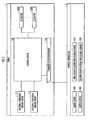
FIG. 2 is an explanatory view of the configuration of the remote controller according to the present invention; -
FIG. 3 is an explanatory view related to the function of the remote controller; -
FIG. 4 is an explanatory view related to the function of the remote controller; and -
FIG. 5 is an explanatory view related to the function of the remote controller. - An embodiment of a remote controller according to the present invention will now be explained below with reference to the accompanying drawings.
- A
robot 1 shown inFIG. 1 is a legged mobile robot as an operation object of aremote controller 2, and is equipped with, as is the same with a human being, abody 10, a head 11 provided to the upper part of thebody 10, left andright arms 12 extended from upper left and right sides of thebody 10, ahand 14 provided to the tip end of thearm 12, left andright legs 13 extended downwardly from the lower portion of thebody 10, and afoot 15 attached to the tip end of theleg 13. As is disclosed in Published Japanese Translation ofPCT Application 03-090978 PCT Application 03-090979 robot 1 is capable of bending and stretching thearm 12 and theleg 13 at a plurality of joints respectively corresponding to human being's plurality of joints such as a shoulder joint, an elbow joint, a carpal joint, a hip joint, a knee joint, a foot joint, by the force transmitted from an actuator 1000 (refer toFIG. 2 ). Therobot 1 is capable of moving autonomously by a movement involving repetition of lifting and landing each of the left and right leg 13 (or foot 15). The height of the head 11 may be adjusted by adjusting the inclination angle of thebody 10 with respect to the vertical direction thereof. The robot may be therobot 1 autonomously moving by the operation of a plurality of theleg 13, or may be any other robot having moving function, such as a wheel-type moving robot (automobile) or the like. - The
robot 1 is equipped with acontrol device 100 configured by an ECU or a computer (configured by a CPU, a ROM, a RAM, an I/O and the like) as a hardware, and acommunication equipment 102. A control program (software) is stored in a memory of the computer. The control program may be installed to the computer through software recording medium such as a CD or DVD, but may be downloaded to the computer from a server via a network or a satellite upon transmission of a request signal from therobot 1 to the server. - The
control device 100 shown inFIG. 2 controls the behavior of therobot 1 in accordance with a command signal which is transmitted from theremote controller 2 and received by thecommunication equipment 102. Thecontrol device 100 controls the operation of thearm 12 and theleg 13, by controlling the operation of theactuator 1000 on the basis of the output signals from an internalcondition sensor group 111 and an externalcondition sensor group 112 or the like. The "internal condition" includes a position of a reference point such as a center of gravity of therobot 1 in a fixed coordinate system, an orientation of a moving direction of therobot 1, a posture determined by the angle of each joint or the like, and a force therobot 1 receives from outside via thehand 14, and the like. The "internal condition sensor group" includes a GPS receiver which receives signals indicating the latitude and the longitude defining the position of therobot 1 from the satellite, a yaw rate sensor outputting signals corresponding to the angular velocity of therobot 1 around z axis, an acceleration sensor outputting signals according to the acceleration of therobot 1 in the X direction or the like, a rotary encoder outputting signals according to the angle of each joint, and a six-axis force sensor outputting signals according to the force acting on thehand 14 from outside, and the like. The "external condition" of therobot 1 includes a position of a representative point of an object W in the fixed coordinate system or a robot coordinate system, a posture of the object W, and a passable region set by a wall of a route or the like. The "external condition sensor group" includes a pair of left and right head camera C1 mounted on the head 11 with the imaging region set to the front of therobot 1, which is capable of perceiving light in various frequency band such as a CCD camera and a infrared camera, a waist camera C2 provided at the bottom of thebody 10 for measuring the position, orientation and the like of the object by detecting the near-infrared laser light emitted with the direction set at lower front of therobot 1 and reflected by the object, and the like (refer toFIG. 1 ). - The
remote controller 2 is equipped with aninput device 201, anoutput device 202, a firstmanipulation processing element 210, and a secondmanipulation processing element 220. Theinput device 201 is configured from an input device of a touch-panel type or a touch-with-pen type, or a voice recognition device and the like, and is capable of making the user input a designated route through manipulation or utterance and the like. Theoutput device 202 is configured from a display device or an audio equipment, and is capable of making the user recognize information on a shape or the like of the designated route visually or auditorily. The firstmanipulation processing element 210 recognizes the designated route input by the user through theinput device 201, and further recognizes the boundary of a designated region QS, and the position and the external shape of the object existing in the designated region (refer toFIG. 4(a) ). The secondmanipulation processing element 220 determines whether or not the designated route satisfies a stable movement requirement, on the basis of the recognition result of the firstmanipulation processing element 210. The "stable movement requirement" is a requirement in which therobot 1 is capable of moving without straying away from the designated region QS as well as in a condition having low possibility of coming into contact with the object. The secondmanipulation processing element 220 transmits a first command signal to therobot 1 on condition that the determination result is positive, that is, it is determined that the designated route satisfies the stable movement requirement. The secondmanipulation processing element 220 transmits a second command signal to therobot 1 on condition that the determination result is negative, that is, it is determined that the designated route does not satisfy the stable movement requirement. - The "recognition" of information by a constituent element in the present invention means to carry out any information processing required to prepare information for further information processing. Such information processing includes, for example, the retrieval of information from a database, reading information from a storage device, such as a memory, measuring, calculating, estimating or judging information on the basis of output signals of sensors and the like, and storing information obtained by measurement or the like in a memory by the constituent element.
- Next, the function of the
remote controller 2 having the above-described configuration will be described below. - The first
manipulation processing element 210 recognizes the designated route input by the user through the input device 201 (S202 inFIG. 3 ). The user may select the shape and the like of the designated route in view of its intention, such as making therobot 1 guide to a target position, or making therobot 1 follow the user. By doing so, as shown inFIG. 4(a) , a first route (dot-and-dash line) R1 or a second route (double dot-and-dash line) R2 connecting a starting point SP and a terminal point TP is recognized as the designated route. The "designated route" is recognized as a quasi-continuous coordinate group in a fixed coordinate defined by latitude and longitude, or by latitude, longitude and height. Here, the designated route may be designated by designating one part of the coordinate group constituting the designated route, such as the starting point SP and the terminal point TP. The firstmanipulation processing element 210 recognizes the boundary of the designated region QS and the position and the external shape of the object existing in the designated region QS, by reading from a memory device, searching the database based on communication with a server (not shown), and the like (S204 inFIG. 3 ). By doing so, the designated region QS of a shape shown inFIG. 4 (a) for example is recognized, and the object is recognized as an object region Q2 in the designated region QS. Similar to the situation for the designated route, the boundary of the designated region QS is defined by the quasi-continuous coordinate group in the fixed coordinate system. Further, the firstmanipulation processing element 210 recognizes therobot 1 as a robot region Q1 having a spatial stretch according to the size such as longitudinal and horizontal width of therobot 1, for example as shown inFIG. 4(b) . - The second
manipulation processing element 220 determines whether or not the designated route satisfies the stable movement requirement, on the basis of the recognition result of the first manipulation processing element 210 (S206 inFIG. 3 ). The "stable movement requirement" is, as described above, a requirement in which therobot 1 is capable of moving without straying away from the designated region QS as well as in a condition having low possibility of coming into contact with the object. For example, if the first route R1 deviating from the designated region QS as shown inFIG. 4(a) is the designated route, it is determined that the designated route does not satisfy the stable movement requirement. Further, if the second route R2 crossing with the object region Q2 as shown inFIG. 4(a) is the designated route, it is determined that the designated route does not satisfy the stable movement requirement. Still further, although in the case where the designated route does not deviate from the designated region QS as shown inFIG. 4(b) , if a part of an extended robot region EQ1, which is formed by extending the robot region Q1 along a third route (dot-and-dash line) R3, deviates from the designated region QS, then it is determined that the third route R3 as the designated route does not satisfy the stable movement requirement. Still further, although in the case where the designated route does not cross the object region Q2 as shown inFIG. 4(b) , if a part of the extended robot region EQ1, which is formed by extending the robot region Q1 along a fourth route (double dot-and-dash line) R4, crosses the object region Q2, then it is determined that the fourth route R4 as the designate route does not satisfy the stable movement requirement. - If the determination result is positive, that is, if it is determined that the designated route satisfies the stable movement requirement (YES in S206 in
FIG. 3 ), the secondmanipulation processing element 220 outputs positive determination result through the output device 202 (S208 inFIG. 3 ), and transmits the first command signal to the robot 1 (S210 inFIG. 3 ). The "first command signal" is a command signal for making therobot 1 move in accordance with the designated route. If the determination result is negative, that is, if it is determined that the designated route does not satisfy the stable movement requirement (NO in S202 inFIG. 3 ), then the secondmanipulation processing element 220 outputs negative determination result through the output device 202 (S212 inFIG. 3 ), and determines whether or not the designated route is input again by the user through the input device 201 (S214 inFIG. 3 ). If the designated route is input again (YES in S214 inFIG. 3 ), then the above-mentioned series of processing is repeated (refer to S202 and the like inFIG. 3 ). If the designated route is not input again (NO in S214 inFIG. 3 ), then the secondmanipulation processing element 220 outputs the content of the second command signal through the output device 202 (S216 inFIG. 3 ), and transmits the second command signal to the robot 1 (S218 inFIG. 3 ). The "second command signal" is a command signal which makes therobot 1 to decelerate or stop when therobot 1 is moving, and then makes therobot 1 search for a route having common terminal point or common starting and terminal points with the designated route and which satisfies the stable movement requirement as the target route, and when the target route is retrieved, makes therobot 1 move in accordance with the target route, and when the target route is not retrieved, makes therobot 1 stop or maintain the stopped state. - When the first command signal is received by the
communication equipment 102 of therobot 1, thecontrol device 100 sets the designated route as the target route (S102 inFIG. 3 ), and controls the operation of therobot 1 so as to move in accordance with the target route (S104 inFIG. 3 ). When the second command signal is received by thecommunication equipment 102 of therobot 1, thecontrol device 100 determines whether or not therobot 1 is moving (S106 inFIG. 3 ). For example, it is determined whether or not therobot 1 is moving on the basis of a changing mode of a reference position of therobot 1 measured by the GPS receiver constituting the internalcondition sensor group 111. If it is determined that the robot is moving (YES in S106 inFIG. 3 ), thecontrol device 100 makes therobot 1 to decelerate or stop (S108 inFIG. 3 ), and searches for a route satisfying the stable movement requirement on the basis of the internal condition and the external condition as the target route (S110 inFIG. 3 ). The "internal condition" includes the position, orientation and the like of the robot R in the fixed coordinate. The "external condition" includes the boundary of the designated region QS and the position and the external shape of the object retrieved from the database on the basis of the communication with the server, the terminal point or the starting point and the terminal point of the designated route received from theremote controller 2 by thecommunication equipment 102, and the like. The position of the user measured by the head camera C1 may be recognized as the terminal point of the designated route. If it is determined that therobot 1 is stopping (NO in S106 inFIG. 3 ), thecontrol device 100 searches for a route satisfying the stable movement requirement as the target route (S110 inFIG. 3 ). Thecontrol device 100 determines whether or not the target route is retrieved (S112 inFIG. 3 ). If the target route is retrieved (YES in S112 inFIG. 3 ), then the operation of therobot 1 is controlled so as to move in accordance with the target route (S104 inFIG. 3 ). On the other hand, if the target route is not retrieved (NO in S112 inFIG. 3 ), then the operation of therobot 1 is controlled so as to make therobot 1 stop or maintain its stopped state (S110 inFIG. 3 ). - According to the
remote controller 2 exerting the above-mentioned function, when the designated route designated by the user satisfies the stable movement requirement, the "first command signal" is transmitted from theremote controller 2 to the robot 1 (refer to S206 and S210 inFIG. 3 ). By doing so, the user may manipulate the behavior of therobot 1 so as to make therobot 1 move in accordance with the designated route, by the use of the remote controller 2 (refer to S102 and S104 inFIG. 3 ). - On the other hand, when the designated route designated by the user does not satisfy the stable movement requirement, not the first command signal but the "second command signal" is transmitted from the
remote controller 2 to the robot 1 (refer to S206 and S218 inFIG. 3 ). For example, as indicated by a white arrow inFIG. 5(a) , when the designated route having the position of therobot 1 as the starting point and the position of the user as the terminal point via an unevenness, which corresponds to the boundary of the designated region or the object, is input to theremote controller 2 by the user, the second command signal is transmitted from theremote controller 2 to therobot 1, by determining that the designated route does not satisfy the stable movement requirement (refer to NO in S206 and S218 inFIG. 3 ). By doing so, the user may manipulate the behavior of therobot 1 to make therobot 1 decelerate or stop before searching for the target route when therobot 1 is moving, by the use of the remote controller 2 (refer to S106 and S108 inFIG. 3 ). - Further, it is possible to make the
robot 1 search for a route satisfying the stable movement requirement as the target route, and if the target route is retrieved, then make therobot 1 move in accordance with the target route, and if the target route is not retrieved, then make therobot 1 stop or maintain its stopped state (refer to S110 through S114 and S104 inFIG. 3 ). For example, as indicated by a white arrow inFIG. 5(b) , the target route which does not make therobot 1 step over the unevenness, but the target route reaching the position of the user measured by the head camera C1 via a slope, which corresponds to the designated region, is retrieved. Here, there are cases where the user is moving. As such, the position of the user measured by therobot 1 may be different from the position of the user in the past, which is input by theremote controller 2 as the terminal point of the designated route. Therefore, even in the case where the designated route not satisfying the stable movement condition is input, the user may manipulate the behavior of therobot 1 so as to make therobot 1 move towards the terminal point of the designated route without straying away from the designated region as well as avoiding contact with the object, by the use of theremote controller 2. For example, as is shown inFIG. 5(c) , it is possible to avoid therobot 1 from contacting the unevenness, by making therobot 1 move in accordance with the target route different from the designated route. - Further, the determination result of whether or not the designated route designated by the user is satisfying the stable movement requirement is output, and also the content of the second command signal is output by the remote controller 2 (refer to S208, S212, and S216 in
FIG. 3 ). By doing so, it is possible to make the user recognize that therobot 1 will be moving in accordance with the designated route designated by the user, or therobot 1 will be moving in accordance with a route different from the designated route or will be stopping, and the like. Therefore, the user may manipulate the behavior of therobot 1 so as to make therobot 1 move without straying away from the designated region as well as avoiding contact with the object, while predicting the behavior mode of therobot 1, by the use of theremote controller 2. - Here, in accordance with either one or both of the first command signal and the second command signal transmitted from the
remote controller 2 to therobot 1, therobot 1 may be operated to notify beforehand the upcoming behavior to the user, such as making therobot 1 output voice from the voice output device (not shown), or making therobot 1 move thearm 12 so as to wave thehand 13 while facing the front of the head 11 towards the user operating theremote controller 2. For example, it may be possible to make therobot 1 output voice such as "I am coming your way" to the user as the object of following, and output voice such as "follow me" to the user as the object of guidance, according to the first command signal. Further, it may be possible to make therobot 1 output voice such as "I will be using a different route", and operate so that the front of the head 11 face the direction towards which the target route travels, according to the second command signal.
Claims (4)
- A remote controller for making a user remotely manipulate a robot moving autonomously, comprising:a first manipulation processing element which recognizes a designated route input by the user via an input device, and which further recognizes a boundary of a designated region and a position and an external shape of an object existing in the designated region; anddetermines whether or not the designated route satisfies a stable movement requirement, which is a requirement in which the robot is capable of moving without straying away from the designated region as well as in a condition having low possibility of coming into contact with the object, on the basis of the recognition result of the first manipulation processing element, and which transmits a first command signal to the robot for making the robot to move according to the designated route, on condition that the determination result is positive.
- The remote controller according to claim 1, wherein the second manipulation processing element transmits a second command signal to the robot on condition that the determination result is negative, the second command signal makes the robot search for a route which has common terminal point or common starting and terminal points with the designated route and which satisfies the stable movement requirement as a target route, and makes the robot move according to the target route when the target route is retrieved, and on the other hand makes the robot stop or maintain the moving state thereof when the target route is not retrieved.
- The remote controller according to Claim 2, wherein the second manipulation controlling element transmits the second command signal to the robot, the second command signal makes the robot decelerate or stop and thereafter search for the target route, when the robot is moving.
- The remote controller according to Claim 1, wherein the second manipulation processing element outputs the determination result in relation to the stable movement requirement, or a behavior mode of the robot defined by the second command signal via an output device.
Applications Claiming Priority (2)
| Application Number | Priority Date | Filing Date | Title |
|---|---|---|---|
| JP2007318497A JP5142137B2 (en) | 2007-12-10 | 2007-12-10 | Remote controller |
| PCT/JP2008/002827 WO2009075048A1 (en) | 2007-12-10 | 2008-10-07 | Remote controller |
Publications (3)
| Publication Number | Publication Date |
|---|---|
| EP2101238A1 true EP2101238A1 (en) | 2009-09-16 |
| EP2101238A4 EP2101238A4 (en) | 2012-01-25 |
| EP2101238B1 EP2101238B1 (en) | 2014-04-30 |
Family
ID=40755299
Family Applications (1)
| Application Number | Title | Priority Date | Filing Date |
|---|---|---|---|
| EP08858903.1A Not-in-force EP2101238B1 (en) | 2007-12-10 | 2008-10-07 | Remote controller |
Country Status (4)
| Country | Link |
|---|---|
| US (1) | US9592610B2 (en) |
| EP (1) | EP2101238B1 (en) |
| JP (1) | JP5142137B2 (en) |
| WO (1) | WO2009075048A1 (en) |
Families Citing this family (18)
| Publication number | Priority date | Publication date | Assignee | Title |
|---|---|---|---|---|
| KR101667032B1 (en) * | 2009-10-30 | 2016-10-17 | 삼성전자 주식회사 | Path planning apparatus of robot and method thereof |
| KR101667031B1 (en) * | 2009-11-02 | 2016-10-17 | 삼성전자 주식회사 | Path planning apparatus of robot and method thereof |
| JP2011201002A (en) * | 2010-03-26 | 2011-10-13 | Sony Corp | Robot device, method and program of remote control of the robot device |
| US20120041599A1 (en) * | 2010-08-11 | 2012-02-16 | Townsend William T | Teleoperator system with master controller device and multiple remote slave devices |
| BR112013005080A2 (en) * | 2010-09-03 | 2018-04-24 | Aldebaran Robotics | control device for a mobile robot |
| JP6062200B2 (en) * | 2012-10-01 | 2017-01-18 | シャープ株式会社 | Device control device and self-propelled electronic device |
| KR101428877B1 (en) * | 2012-12-05 | 2014-08-14 | 엘지전자 주식회사 | A robot cleaner |
| US9561829B1 (en) * | 2014-09-03 | 2017-02-07 | X Development Llc | Robotic leg with multiple robotic feet |
| JP6545472B2 (en) * | 2015-01-27 | 2019-07-17 | 蛇の目ミシン工業株式会社 | robot |
| JP2018120524A (en) * | 2017-01-27 | 2018-08-02 | 日本精工株式会社 | Guide robot |
| CN107390685B (en) * | 2017-07-14 | 2020-10-16 | 深圳市优必选科技有限公司 | Robot recharging control method, robot and robot system |
| US10575699B2 (en) | 2018-01-05 | 2020-03-03 | Irobot Corporation | System for spot cleaning by a mobile robot |
| JP7124797B2 (en) * | 2019-06-28 | 2022-08-24 | トヨタ自動車株式会社 | Machine learning methods and mobile robots |
| JP7356829B2 (en) * | 2019-07-10 | 2023-10-05 | ヤンマーパワーテクノロジー株式会社 | automatic driving system |
| US11797016B2 (en) | 2020-04-13 | 2023-10-24 | Boston Dynamics, Inc. | Online authoring of robot autonomy applications |
| CN117769484A (en) * | 2021-06-04 | 2024-03-26 | 波士顿动力公司 | Autonomous and remotely operated sensors for mobile robots |
| KR102802665B1 (en) * | 2022-06-16 | 2025-05-07 | 한국전자통신연구원 | Method of Controlling Movement of a Mobile Robot Between User Regions |
| WO2024232947A1 (en) | 2023-05-08 | 2024-11-14 | Boston Dynamics, Inc. | Location based change detection within image data by a mobile robot |
Family Cites Families (22)
| Publication number | Priority date | Publication date | Assignee | Title |
|---|---|---|---|---|
| JPS6195414A (en) * | 1984-10-17 | 1986-05-14 | Hitachi Ltd | Route searching system of moving car |
| JP2525046B2 (en) * | 1988-10-19 | 1996-08-14 | 株式会社ロボテック研究所 | Mobile remote control system |
| US5461292A (en) * | 1994-07-18 | 1995-10-24 | Zondlo; Robert | Remote controlled guidance system for working vehicle |
| US6574536B1 (en) * | 1996-01-29 | 2003-06-03 | Minolta Co., Ltd. | Moving apparatus for efficiently moving on floor with obstacle |
| JPH09212229A (en) * | 1996-01-30 | 1997-08-15 | Komatsu Ltd | Robot teaching device |
| JPH09212225A (en) * | 1996-01-30 | 1997-08-15 | Komatsu Ltd | Robot teaching device |
| US5987383C1 (en) * | 1997-04-28 | 2006-06-13 | Trimble Navigation Ltd | Form line following guidance system |
| US6633800B1 (en) * | 2001-01-31 | 2003-10-14 | Ainsworth Inc. | Remote control system |
| JP3906743B2 (en) | 2002-05-27 | 2007-04-18 | 松下電工株式会社 | Guide robot |
| KR100483548B1 (en) * | 2002-07-26 | 2005-04-15 | 삼성광주전자 주식회사 | Robot cleaner and system and method of controlling thereof |
| JP2004299025A (en) | 2003-04-01 | 2004-10-28 | Honda Motor Co Ltd | Mobile robot control device, mobile robot control method, and mobile robot control program |
| JP2005211359A (en) * | 2004-01-30 | 2005-08-11 | Funai Electric Co Ltd | Autonomous traveling robot cleaner system |
| JP4646943B2 (en) * | 2004-07-13 | 2011-03-09 | パナソニック株式会社 | robot |
| KR100641113B1 (en) * | 2004-07-30 | 2006-11-02 | 엘지전자 주식회사 | Mobile robot and its movement control method |
| JP4264395B2 (en) | 2004-08-06 | 2009-05-13 | シャープ株式会社 | Self-propelled mobile vehicle |
| JP2006113858A (en) * | 2004-10-15 | 2006-04-27 | Mitsubishi Heavy Ind Ltd | Method and system for supporting remote control of moving object |
| JP4462156B2 (en) * | 2005-03-15 | 2010-05-12 | パナソニック電工株式会社 | Autonomous mobile device |
| JP4375320B2 (en) * | 2005-10-27 | 2009-12-02 | 株式会社日立製作所 | Mobile robot |
| WO2008013568A2 (en) * | 2005-12-30 | 2008-01-31 | Irobot Corporation | Autonomous mobile robot |
| JP2007226322A (en) * | 2006-02-21 | 2007-09-06 | Sharp Corp | Robot control system |
| JP4577247B2 (en) * | 2006-03-22 | 2010-11-10 | トヨタ自動車株式会社 | Mobile body and control method thereof |
| US8326469B2 (en) * | 2006-07-14 | 2012-12-04 | Irobot Corporation | Autonomous behaviors for a remote vehicle |
-
2007
- 2007-12-10 JP JP2007318497A patent/JP5142137B2/en not_active Expired - Fee Related
-
2008
- 2008-10-07 US US12/521,828 patent/US9592610B2/en not_active Expired - Fee Related
- 2008-10-07 EP EP08858903.1A patent/EP2101238B1/en not_active Not-in-force
- 2008-10-07 WO PCT/JP2008/002827 patent/WO2009075048A1/en not_active Ceased
Also Published As
| Publication number | Publication date |
|---|---|
| WO2009075048A1 (en) | 2009-06-18 |
| JP5142137B2 (en) | 2013-02-13 |
| EP2101238A4 (en) | 2012-01-25 |
| US9592610B2 (en) | 2017-03-14 |
| EP2101238B1 (en) | 2014-04-30 |
| JP2009136988A (en) | 2009-06-25 |
| US20100036527A1 (en) | 2010-02-11 |
Similar Documents
| Publication | Publication Date | Title |
|---|---|---|
| EP2101238B1 (en) | Remote controller | |
| US8204679B2 (en) | Mobile apparatus, control device and control program | |
| US8103383B2 (en) | Mobile apparatus, control device and control program | |
| US7873438B2 (en) | Mobile apparatus and control program therefor | |
| KR101240181B1 (en) | Method and apparatus and for generating safe path of mobile robot | |
| US8392036B2 (en) | Point and go navigation system and method | |
| US8116928B2 (en) | Automatic ultrasonic and computer-vision navigation device and method using the same | |
| JP4316477B2 (en) | Tracking method of mobile robot | |
| CN109605363B (en) | Robot voice control system and method | |
| CN103822625B (en) | Line-tracking navigation method and device for intelligent robot | |
| US8401725B2 (en) | Target route setting support system | |
| JP5035802B2 (en) | Robot and task execution system | |
| CN108180901A (en) | Indoor navigation method, device, robot and the storage medium of blind-guidance robot | |
| KR20130073476A (en) | Mobile apparatus and localization method of mobile apparatus | |
| US20080154391A1 (en) | Mobile apparatus, and control method thereof, control program and supervisory system therefor | |
| WO2009089369A1 (en) | Point and go navigation system and method | |
| JP5085251B2 (en) | Autonomous mobile device | |
| Tuvshinjargal et al. | Hybrid motion planning method for autonomous robots using kinect based sensor fusion and virtual plane approach in dynamic environments | |
| KR20160133318A (en) | Smart walking assistance device for the blind and Smart walking assistance system using the same | |
| US8082063B2 (en) | Mobile apparatus and mobile apparatus system | |
| JP2010046780A (en) | Route guiding robot | |
| KR20180092103A (en) | A Robot Dog for a Person Having a Impaired Eyesight | |
| CN114593726B (en) | Path smoothing method and device | |
| CN116772851A (en) | Positioning method, positioning device, robot and storage medium | |
| JP2008257532A (en) | MOBILE DEVICE, ITS CONTROL METHOD, CONTROL PROGRAM, AND SUPERVISION SYSTEM |
Legal Events
| Date | Code | Title | Description |
|---|---|---|---|
| PUAI | Public reference made under article 153(3) epc to a published international application that has entered the european phase |
Free format text: ORIGINAL CODE: 0009012 |
|
| 17P | Request for examination filed |
Effective date: 20090630 |
|
| AK | Designated contracting states |
Kind code of ref document: A1 Designated state(s): AT BE BG CH CY CZ DE DK EE ES FI FR GB GR HR HU IE IS IT LI LT LU LV MC MT NL NO PL PT RO SE SI SK TR |
|
| DAX | Request for extension of the european patent (deleted) | ||
| A4 | Supplementary search report drawn up and despatched |
Effective date: 20111228 |
|
| RIC1 | Information provided on ipc code assigned before grant |
Ipc: B25J 5/00 20060101ALI20111221BHEP Ipc: B25J 13/02 20060101ALI20111221BHEP Ipc: B25J 19/06 20060101ALI20111221BHEP Ipc: B62D 57/032 20060101ALI20111221BHEP Ipc: G05D 1/00 20060101AFI20111221BHEP |
|
| 17Q | First examination report despatched |
Effective date: 20120726 |
|
| GRAP | Despatch of communication of intention to grant a patent |
Free format text: ORIGINAL CODE: EPIDOSNIGR1 |
|
| INTG | Intention to grant announced |
Effective date: 20131216 |
|
| GRAS | Grant fee paid |
Free format text: ORIGINAL CODE: EPIDOSNIGR3 |
|
| GRAA | (expected) grant |
Free format text: ORIGINAL CODE: 0009210 |
|
| AK | Designated contracting states |
Kind code of ref document: B1 Designated state(s): AT BE BG CH CY CZ DE DK EE ES FI FR GB GR HR HU IE IS IT LI LT LU LV MC MT NL NO PL PT RO SE SI SK TR |
|
| REG | Reference to a national code |
Ref country code: GB Ref legal event code: FG4D Ref country code: CH Ref legal event code: EP |
|
| REG | Reference to a national code |
Ref country code: AT Ref legal event code: REF Ref document number: 665514 Country of ref document: AT Kind code of ref document: T Effective date: 20140515 |
|
| REG | Reference to a national code |
Ref country code: IE Ref legal event code: FG4D |
|
| REG | Reference to a national code |
Ref country code: DE Ref legal event code: R096 Ref document number: 602008031929 Country of ref document: DE Effective date: 20140612 |
|
| REG | Reference to a national code |
Ref country code: AT Ref legal event code: MK05 Ref document number: 665514 Country of ref document: AT Kind code of ref document: T Effective date: 20140430 |
|
| REG | Reference to a national code |
Ref country code: LT Ref legal event code: MG4D |
|
| REG | Reference to a national code |
Ref country code: NL Ref legal event code: VDEP Effective date: 20140430 |
|
| PG25 | Lapsed in a contracting state [announced via postgrant information from national office to epo] |
Ref country code: FI Free format text: LAPSE BECAUSE OF FAILURE TO SUBMIT A TRANSLATION OF THE DESCRIPTION OR TO PAY THE FEE WITHIN THE PRESCRIBED TIME-LIMIT Effective date: 20140430 Ref country code: LT Free format text: LAPSE BECAUSE OF FAILURE TO SUBMIT A TRANSLATION OF THE DESCRIPTION OR TO PAY THE FEE WITHIN THE PRESCRIBED TIME-LIMIT Effective date: 20140430 Ref country code: NO Free format text: LAPSE BECAUSE OF FAILURE TO SUBMIT A TRANSLATION OF THE DESCRIPTION OR TO PAY THE FEE WITHIN THE PRESCRIBED TIME-LIMIT Effective date: 20140730 Ref country code: NL Free format text: LAPSE BECAUSE OF FAILURE TO SUBMIT A TRANSLATION OF THE DESCRIPTION OR TO PAY THE FEE WITHIN THE PRESCRIBED TIME-LIMIT Effective date: 20140430 Ref country code: GR Free format text: LAPSE BECAUSE OF FAILURE TO SUBMIT A TRANSLATION OF THE DESCRIPTION OR TO PAY THE FEE WITHIN THE PRESCRIBED TIME-LIMIT Effective date: 20140731 Ref country code: BG Free format text: LAPSE BECAUSE OF FAILURE TO SUBMIT A TRANSLATION OF THE DESCRIPTION OR TO PAY THE FEE WITHIN THE PRESCRIBED TIME-LIMIT Effective date: 20140730 Ref country code: IS Free format text: LAPSE BECAUSE OF FAILURE TO SUBMIT A TRANSLATION OF THE DESCRIPTION OR TO PAY THE FEE WITHIN THE PRESCRIBED TIME-LIMIT Effective date: 20140830 Ref country code: CY Free format text: LAPSE BECAUSE OF FAILURE TO SUBMIT A TRANSLATION OF THE DESCRIPTION OR TO PAY THE FEE WITHIN THE PRESCRIBED TIME-LIMIT Effective date: 20140430 |
|
| PG25 | Lapsed in a contracting state [announced via postgrant information from national office to epo] |
Ref country code: AT Free format text: LAPSE BECAUSE OF FAILURE TO SUBMIT A TRANSLATION OF THE DESCRIPTION OR TO PAY THE FEE WITHIN THE PRESCRIBED TIME-LIMIT Effective date: 20140430 Ref country code: ES Free format text: LAPSE BECAUSE OF FAILURE TO SUBMIT A TRANSLATION OF THE DESCRIPTION OR TO PAY THE FEE WITHIN THE PRESCRIBED TIME-LIMIT Effective date: 20140430 Ref country code: PL Free format text: LAPSE BECAUSE OF FAILURE TO SUBMIT A TRANSLATION OF THE DESCRIPTION OR TO PAY THE FEE WITHIN THE PRESCRIBED TIME-LIMIT Effective date: 20140430 Ref country code: LV Free format text: LAPSE BECAUSE OF FAILURE TO SUBMIT A TRANSLATION OF THE DESCRIPTION OR TO PAY THE FEE WITHIN THE PRESCRIBED TIME-LIMIT Effective date: 20140430 Ref country code: HR Free format text: LAPSE BECAUSE OF FAILURE TO SUBMIT A TRANSLATION OF THE DESCRIPTION OR TO PAY THE FEE WITHIN THE PRESCRIBED TIME-LIMIT Effective date: 20140430 Ref country code: SE Free format text: LAPSE BECAUSE OF FAILURE TO SUBMIT A TRANSLATION OF THE DESCRIPTION OR TO PAY THE FEE WITHIN THE PRESCRIBED TIME-LIMIT Effective date: 20140430 |
|
| PG25 | Lapsed in a contracting state [announced via postgrant information from national office to epo] |
Ref country code: PT Free format text: LAPSE BECAUSE OF FAILURE TO SUBMIT A TRANSLATION OF THE DESCRIPTION OR TO PAY THE FEE WITHIN THE PRESCRIBED TIME-LIMIT Effective date: 20140901 |
|
| PG25 | Lapsed in a contracting state [announced via postgrant information from national office to epo] |
Ref country code: BE Free format text: LAPSE BECAUSE OF FAILURE TO SUBMIT A TRANSLATION OF THE DESCRIPTION OR TO PAY THE FEE WITHIN THE PRESCRIBED TIME-LIMIT Effective date: 20140430 Ref country code: RO Free format text: LAPSE BECAUSE OF FAILURE TO SUBMIT A TRANSLATION OF THE DESCRIPTION OR TO PAY THE FEE WITHIN THE PRESCRIBED TIME-LIMIT Effective date: 20140430 Ref country code: DK Free format text: LAPSE BECAUSE OF FAILURE TO SUBMIT A TRANSLATION OF THE DESCRIPTION OR TO PAY THE FEE WITHIN THE PRESCRIBED TIME-LIMIT Effective date: 20140430 Ref country code: EE Free format text: LAPSE BECAUSE OF FAILURE TO SUBMIT A TRANSLATION OF THE DESCRIPTION OR TO PAY THE FEE WITHIN THE PRESCRIBED TIME-LIMIT Effective date: 20140430 Ref country code: SK Free format text: LAPSE BECAUSE OF FAILURE TO SUBMIT A TRANSLATION OF THE DESCRIPTION OR TO PAY THE FEE WITHIN THE PRESCRIBED TIME-LIMIT Effective date: 20140430 Ref country code: CZ Free format text: LAPSE BECAUSE OF FAILURE TO SUBMIT A TRANSLATION OF THE DESCRIPTION OR TO PAY THE FEE WITHIN THE PRESCRIBED TIME-LIMIT Effective date: 20140430 |
|
| REG | Reference to a national code |
Ref country code: DE Ref legal event code: R097 Ref document number: 602008031929 Country of ref document: DE |
|
| PLBE | No opposition filed within time limit |
Free format text: ORIGINAL CODE: 0009261 |
|
| STAA | Information on the status of an ep patent application or granted ep patent |
Free format text: STATUS: NO OPPOSITION FILED WITHIN TIME LIMIT |
|
| PG25 | Lapsed in a contracting state [announced via postgrant information from national office to epo] |
Ref country code: IT Free format text: LAPSE BECAUSE OF FAILURE TO SUBMIT A TRANSLATION OF THE DESCRIPTION OR TO PAY THE FEE WITHIN THE PRESCRIBED TIME-LIMIT Effective date: 20140430 |
|
| 26N | No opposition filed |
Effective date: 20150202 |
|
| REG | Reference to a national code |
Ref country code: DE Ref legal event code: R097 Ref document number: 602008031929 Country of ref document: DE Effective date: 20150202 |
|
| PG25 | Lapsed in a contracting state [announced via postgrant information from national office to epo] |
Ref country code: MC Free format text: LAPSE BECAUSE OF FAILURE TO SUBMIT A TRANSLATION OF THE DESCRIPTION OR TO PAY THE FEE WITHIN THE PRESCRIBED TIME-LIMIT Effective date: 20140430 Ref country code: LU Free format text: LAPSE BECAUSE OF FAILURE TO SUBMIT A TRANSLATION OF THE DESCRIPTION OR TO PAY THE FEE WITHIN THE PRESCRIBED TIME-LIMIT Effective date: 20141007 |
|
| REG | Reference to a national code |
Ref country code: CH Ref legal event code: PL |
|
| GBPC | Gb: european patent ceased through non-payment of renewal fee |
Effective date: 20141007 |
|
| REG | Reference to a national code |
Ref country code: IE Ref legal event code: MM4A |
|
| PG25 | Lapsed in a contracting state [announced via postgrant information from national office to epo] |
Ref country code: CH Free format text: LAPSE BECAUSE OF NON-PAYMENT OF DUE FEES Effective date: 20141031 Ref country code: GB Free format text: LAPSE BECAUSE OF NON-PAYMENT OF DUE FEES Effective date: 20141007 Ref country code: LI Free format text: LAPSE BECAUSE OF NON-PAYMENT OF DUE FEES Effective date: 20141031 Ref country code: SI Free format text: LAPSE BECAUSE OF FAILURE TO SUBMIT A TRANSLATION OF THE DESCRIPTION OR TO PAY THE FEE WITHIN THE PRESCRIBED TIME-LIMIT Effective date: 20140430 |
|
| REG | Reference to a national code |
Ref country code: FR Ref legal event code: ST Effective date: 20150630 |
|
| PG25 | Lapsed in a contracting state [announced via postgrant information from national office to epo] |
Ref country code: FR Free format text: LAPSE BECAUSE OF NON-PAYMENT OF DUE FEES Effective date: 20141031 |
|
| PG25 | Lapsed in a contracting state [announced via postgrant information from national office to epo] |
Ref country code: IE Free format text: LAPSE BECAUSE OF NON-PAYMENT OF DUE FEES Effective date: 20141007 |
|
| PG25 | Lapsed in a contracting state [announced via postgrant information from national office to epo] |
Ref country code: MT Free format text: LAPSE BECAUSE OF FAILURE TO SUBMIT A TRANSLATION OF THE DESCRIPTION OR TO PAY THE FEE WITHIN THE PRESCRIBED TIME-LIMIT Effective date: 20140430 Ref country code: TR Free format text: LAPSE BECAUSE OF FAILURE TO SUBMIT A TRANSLATION OF THE DESCRIPTION OR TO PAY THE FEE WITHIN THE PRESCRIBED TIME-LIMIT Effective date: 20140430 Ref country code: HU Free format text: LAPSE BECAUSE OF FAILURE TO SUBMIT A TRANSLATION OF THE DESCRIPTION OR TO PAY THE FEE WITHIN THE PRESCRIBED TIME-LIMIT; INVALID AB INITIO Effective date: 20081007 |
|
| PGFP | Annual fee paid to national office [announced via postgrant information from national office to epo] |
Ref country code: DE Payment date: 20210831 Year of fee payment: 14 |
|
| REG | Reference to a national code |
Ref country code: DE Ref legal event code: R119 Ref document number: 602008031929 Country of ref document: DE |
|
| PG25 | Lapsed in a contracting state [announced via postgrant information from national office to epo] |
Ref country code: DE Free format text: LAPSE BECAUSE OF NON-PAYMENT OF DUE FEES Effective date: 20230503 |