EP2100811A2 - Frame assembly for electrical bond - Google Patents
Frame assembly for electrical bond Download PDFInfo
- Publication number
- EP2100811A2 EP2100811A2 EP08022570A EP08022570A EP2100811A2 EP 2100811 A2 EP2100811 A2 EP 2100811A2 EP 08022570 A EP08022570 A EP 08022570A EP 08022570 A EP08022570 A EP 08022570A EP 2100811 A2 EP2100811 A2 EP 2100811A2
- Authority
- EP
- European Patent Office
- Prior art keywords
- frame
- contact surface
- assembly
- composite panel
- recited
- Prior art date
- Legal status (The legal status is an assumption and is not a legal conclusion. Google has not performed a legal analysis and makes no representation as to the accuracy of the status listed.)
- Granted
Links
- 239000002131 composite material Substances 0.000 claims abstract description 41
- 238000004891 communication Methods 0.000 claims abstract description 12
- 238000000034 method Methods 0.000 claims description 6
- 229910052782 aluminium Inorganic materials 0.000 description 5
- XAGFODPZIPBFFR-UHFFFAOYSA-N aluminium Chemical compound [Al] XAGFODPZIPBFFR-UHFFFAOYSA-N 0.000 description 5
- 230000008901 benefit Effects 0.000 description 4
- 230000000694 effects Effects 0.000 description 4
- 238000009434 installation Methods 0.000 description 4
- 239000004020 conductor Substances 0.000 description 3
- 239000000853 adhesive Substances 0.000 description 2
- 230000001070 adhesive effect Effects 0.000 description 2
- 238000012986 modification Methods 0.000 description 2
- 230000004048 modification Effects 0.000 description 2
- 230000006835 compression Effects 0.000 description 1
- 238000007906 compression Methods 0.000 description 1
- 230000001419 dependent effect Effects 0.000 description 1
- 230000005672 electromagnetic field Effects 0.000 description 1
- 238000012423 maintenance Methods 0.000 description 1
- 238000004519 manufacturing process Methods 0.000 description 1
- 229910052751 metal Inorganic materials 0.000 description 1
- 239000002184 metal Substances 0.000 description 1
- 230000000116 mitigating effect Effects 0.000 description 1
- 238000007789 sealing Methods 0.000 description 1
- XLYOFNOQVPJJNP-UHFFFAOYSA-N water Substances O XLYOFNOQVPJJNP-UHFFFAOYSA-N 0.000 description 1
Images


Classifications
-
- B—PERFORMING OPERATIONS; TRANSPORTING
- B64—AIRCRAFT; AVIATION; COSMONAUTICS
- B64D—EQUIPMENT FOR FITTING IN OR TO AIRCRAFT; FLIGHT SUITS; PARACHUTES; ARRANGEMENT OR MOUNTING OF POWER PLANTS OR PROPULSION TRANSMISSIONS IN AIRCRAFT
- B64D45/00—Aircraft indicators or protectors not otherwise provided for
- B64D45/02—Lightning protectors; Static dischargers
Definitions
- the present invention relates to a frame assembly which provides an electrical bond surface for a component installed on an opposite side of a screened mesh composite panel.
- EMI effects can disrupt the operation of on board electronic components through generation of unwanted voltage and current fluctuations in the wiring. These EMI effects may potentially damage the electronic components.
- a common method of mitigating the potential damage from EMI effects is to place a continuous conductive shield around the electronic components which may be at risk.
- a metallic outer skin of the aircraft operates as such a shield.
- portions of an aircraft skin are often manufactured from composite materials which are relatively poor conductors and are not effective shields against EMI effects.
- the composite material thereby often incorporate a metallic conductive layer or wire mesh as part of the composite skin panel to operate as a conductor and form at least a portion of an aircraft electrical ground plane.
- the aircraft composite skin may mount various antennas.
- a conductive path between the antenna and the metallic conductive layer is required.
- the conductive path between the antenna and the metallic conductive layer may be conventionally provided by a bond strap or other procedure.
- One procedure utilizes aluminum tape affixed to the exposed screen mesh on an interior surface of the composite panel and wrapped around the circumference of the antenna mount opening to an exterior surface.
- the antenna is then mounted on the exterior surface of composite panel and in contact with the aluminum tape to provide communication with the aircraft electrical ground plane.
- each piece of aluminum tape must be laboriously cut and applied which may induce variability in the application.
- Each piece of tape must also be edge sealed to reduce the likelihood of any portions of the tape peeling away from the contacting surfaces and minimize moisture communication under the tape.
- the aluminum tape may not provide a consistent electrical connection while the degree of electrical conductivity is dependent on the area of surface contact through the adhesive side of the tape which is for the most part non-conductive.
- a frame assembly includes: a first frame having a first frame contact surface transverse to a first frame mount surface; and a second frame having a second frame contact surface transverse to a second frame mount surface, the first frame contact surface receivable within the second frame contact surface to provide a conductive communication path therebetween.
- a composite panel includes: a composite panel having an electrically conductive surface and an aperture therethrough; a first frame having a first frame contact surface transverse to a first frame mount surface, the first frame mount surface mounted to an outer surface of the composite panel about a periphery of the aperture, the first frame contact surface extends at least partially into the aperture; and a second frame having an second frame contact surface transverse to a second frame mount surface, the second frame mount surface mounted to an inner surface of the composite panel about the periphery of the aperture and in contact with the electrically conductive surface, the first frame contact surface receivable within the second frame contact surface to provide a conductive communication path therebetween.
- a method of mounting an antenna within a composite panel includes: sandwiching a composite panel having an electrically conductive surface on an internal surface of the composite panel between a first frame and a second frame, a first frame mount surface receivable within a second frame mount surface to provide a conductive communication path therebetween; and mounting an antenna to the first frame, the antenna having a conductive communication path through the first frame and the second frame to the electrically conductive surface.
- FIG. 1 schematically illustrates an exemplary vertical takeoff and landing (VTOL) rotary-wing aircraft 10.
- the aircraft 10 in the disclosed, non-limiting embodiment includes a main rotor system 12 supported by an airframe 14 having an extending tail 16 which mounts an anti-torque system 18 such as a tail rotor system.
- the main rotor assembly 12 is driven about an axis of rotation R through a main gearbox (illustrated schematically at 20) by one or more engines 22.
- the main rotor system 12 includes a multiple of rotor blades 24 mounted to a rotor hub 26.
- a particular helicopter configuration is illustrated and described in the disclosed embodiment, other configurations and/or machines, such as fixed wing aircraft, tilt-rotor aircraft, tilt-wing aircraft, land vehicles and water vehicles will also benefit herefrom.
- the aircraft 10 often includes an electrical component 30 mounted within a composite panel 32 having an exposed electrically conductive surface 32G such as a wire mesh screen on an interior surface of the composite panel 32 to define, at least in part, an aircraft electrical groundplane ( Figure 3A ).
- component as used herein may include any navigation, identification, alert system, radar warning receiver, IFF system and the like which utilize an antenna or other transmitter/receiver which need communicate with an aircraft electrical groundplane.
- the component 30 need not be an antenna but any removable structure such as an access panel within the composite panel 32.
- the component 30 is mounted at least partially within an aperture 32A of the composite panel 32.
- a frame assembly 34 retains the component 30 within or adjacent the aperture 32A and provides for electrical communication between the component 30 and the exposed electrically conductive surface 32G on the interior surface of the composite panel 32.
- the frame assembly 34 includes an outer frame 36 and an inner frame 38.
- the frames 36, 38 may be manufacture from a conductive material such as aluminum. It should be understood that although an annular frame assembly 34 is illustrated in the disclosed non-limiting embodiment, any shape may alternatively or additionally be provided to receive the component 30 or otherwise provide for a continuous conductive path.
- the outer frame 36 is mountable to an outer surface of the composite panel 32 and the inner frame 38 is mountable to the inner surface of the composite panel 32 to contact the electrically conductive surface 32G and thereby communicate with the aircraft electrical groundplane.
- the outer frame 36 includes a contact surface 36C which is transverse to a mount surface 36M (also illustrated Figure 3C ).
- the inner frame 38 includes a contact surface 38C which is transverse to a mount surface 38M (also illustrated Figure 3C ).
- a multiple of fasteners 40 such as screws, rivets or such like hardware are mounted though the mount surface 36M, the composite panel 32 and the mount surface 38M to affix the outer frame 36 and inner frame 38 to the composite panel 32 about the aperture 32A.
- the fasteners 40 may additionally be utilized to mount the component 30 to the composite panel 32.
- the composite panel contact areas may be prepared specifically for each particular installation though location of mount holes 40M predrilled in the composite panel 32 which align with holes 36H, 38H in the respective corresponding outer frame 36 and inner frame 38 mount surface 36M, 38M coordinates.
- the outer frame 36 mount surface 36M provides an electrical contact area for the component 30 while the inner frame 38 mount surface 38M provides electrical contact with the electrically conductive surface 32G.
- the component fasteners 40 are tightened, the component 30 makes electrical contact with outer frame 36 through to the inner frame 38 and ultimately to the electrically conductive surface 32G on the inside of the composite panel 32.
- Edge sealing may additionally be applied to exposed areas of the frame assembly 34 and the inner and outer areas of the composite panel 32.
- a multiple of fasteners 42 such as a screws, rivets or such like hardware are mounted though the contact surfaces 36C, 38C to provide electrical contact between the outer frame 36 and the inner frame 38 within the aperture 32A ( Figure 3B ).
- the electrical groundplane is thereby transferred from the electrically conductive surface 32G, through the inner frame 38 and to the outer frame 36 via the frame-to-frame contact surface 36C, 38C interface.
- the frame assembly 34 provides consistent positive electrical contact with the electrically conductive surface 32G though through compression by the fasteners 40 which sandwich the composite panel 32 between the mount surface 36M, 38M rather than via pressure contact through a mostly nonconductive adhesive.
- the frame assembly 34 contact is readily duplicated from installation to installation by any installer.
- the frame assembly 34 also provides an effective electrical bonding-mating surface for the component 30 yet can be removed, cleaned, properly surface prepared, and reinstalled in the field by any maintenance personnel if necessary.
- a frame assembly 34A in accords with another non-limiting embodiment provides segmented contact surfaces 36CA, 38CA.
- the segmented contact surfaces 36CA, 38CA facilitate a light weight structure and installation in non planar panels.
- a frame assembly 34B in accords with another non-limiting embodiment provides a continuous conductive path between adjacent panels such as an access panel 32AP within the composite panel 32. That is, the component 30 may be the access panel 32AP with an electrically conductive surface 32APG which interfaces with the electrically conductive surface 32G within the composite panel 32 through the frame assembly 34B to provide a contiguous EMI shield.
Landscapes
- Engineering & Computer Science (AREA)
- Aviation & Aerospace Engineering (AREA)
- Shielding Devices Or Components To Electric Or Magnetic Fields (AREA)
- Casings For Electric Apparatus (AREA)
Abstract
Description
- The present invention relates to a frame assembly which provides an electrical bond surface for a component installed on an opposite side of a screened mesh composite panel.
- External electromagnetic fields, referred to as EMI effects, can disrupt the operation of on board electronic components through generation of unwanted voltage and current fluctuations in the wiring. These EMI effects may potentially damage the electronic components.
- A common method of mitigating the potential damage from EMI effects is to place a continuous conductive shield around the electronic components which may be at risk. Often a metallic outer skin of the aircraft operates as such a shield. However, portions of an aircraft skin are often manufactured from composite materials which are relatively poor conductors and are not effective shields against EMI effects. The composite material thereby often incorporate a metallic conductive layer or wire mesh as part of the composite skin panel to operate as a conductor and form at least a portion of an aircraft electrical ground plane.
- On some aircraft, the aircraft composite skin may mount various antennas. For the antenna to achieve proper performance, a conductive path between the antenna and the metallic conductive layer is required. The conductive path between the antenna and the metallic conductive layer may be conventionally provided by a bond strap or other procedure.
- One procedure utilizes aluminum tape affixed to the exposed screen mesh on an interior surface of the composite panel and wrapped around the circumference of the antenna mount opening to an exterior surface. The antenna is then mounted on the exterior surface of composite panel and in contact with the aluminum tape to provide communication with the aircraft electrical ground plane.
- Although effective, each piece of aluminum tape must be laboriously cut and applied which may induce variability in the application. Each piece of tape must also be edge sealed to reduce the likelihood of any portions of the tape peeling away from the contacting surfaces and minimize moisture communication under the tape. Disadvantageously, even when consistently applied, the aluminum tape may not provide a consistent electrical connection while the degree of electrical conductivity is dependent on the area of surface contact through the adhesive side of the tape which is for the most part non-conductive.
- A frame assembly according to an exemplary aspect of the present invention includes: a first frame having a first frame contact surface transverse to a first frame mount surface; and a second frame having a second frame contact surface transverse to a second frame mount surface, the first frame contact surface receivable within the second frame contact surface to provide a conductive communication path therebetween.
- A composite panel according to an exemplary aspect of the present invention includes: a composite panel having an electrically conductive surface and an aperture therethrough; a first frame having a first frame contact surface transverse to a first frame mount surface, the first frame mount surface mounted to an outer surface of the composite panel about a periphery of the aperture, the first frame contact surface extends at least partially into the aperture; and a second frame having an second frame contact surface transverse to a second frame mount surface, the second frame mount surface mounted to an inner surface of the composite panel about the periphery of the aperture and in contact with the electrically conductive surface, the first frame contact surface receivable within the second frame contact surface to provide a conductive communication path therebetween.
- A method of mounting an antenna within a composite panel according to an exemplary aspect of the present invention includes: sandwiching a composite panel having an electrically conductive surface on an internal surface of the composite panel between a first frame and a second frame, a first frame mount surface receivable within a second frame mount surface to provide a conductive communication path therebetween; and mounting an antenna to the first frame, the antenna having a conductive communication path through the first frame and the second frame to the electrically conductive surface.
- The various features and advantages of this invention will become apparent to those skilled in the art from the following detailed description of the disclosed non-limiting embodiment. The drawings that accompany the detailed description can be briefly described as follows:
-
Figure 1 is a general perspective view of one exemplary rotary wing aircraft embodiment for use with the present invention; -
Figure 2 is a general perspective view of the rotary wing aircraft embodiment ofFigure 1 illustrating an antenna mount location; -
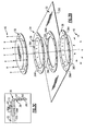
Figure 3B is an exploded view of a frame assembly for mount of an antenna; -
Figure 3B is an exploded view a frame assembly for an antenna; -
Figure 3C is a sectional view of the frame assembly of Figure 3BA taken alongline 3C-3C infigure 3B ; -
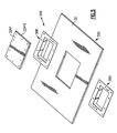
Figure 4 is an exploded view of another non-limiting embodiment of a frame assembly for an antenna; and -
Figure 5 is an exploded view of another non-limiting embodiment of a frame assembly for an access panel to provide a contiguous EMI shield. -
Figure 1 schematically illustrates an exemplary vertical takeoff and landing (VTOL) rotary-wing aircraft 10. Theaircraft 10 in the disclosed, non-limiting embodiment includes amain rotor system 12 supported by anairframe 14 having an extendingtail 16 which mounts ananti-torque system 18 such as a tail rotor system. Themain rotor assembly 12 is driven about an axis of rotation R through a main gearbox (illustrated schematically at 20) by one ormore engines 22. Themain rotor system 12 includes a multiple of rotor blades 24 mounted to a rotor hub 26. Although a particular helicopter configuration is illustrated and described in the disclosed embodiment, other configurations and/or machines, such as fixed wing aircraft, tilt-rotor aircraft, tilt-wing aircraft, land vehicles and water vehicles will also benefit herefrom. - Referring to
Figure 2 , theaircraft 10 often includes anelectrical component 30 mounted within acomposite panel 32 having an exposed electricallyconductive surface 32G such as a wire mesh screen on an interior surface of thecomposite panel 32 to define, at least in part, an aircraft electrical groundplane (Figure 3A ). It should be understood that "component" as used herein may include any navigation, identification, alert system, radar warning receiver, IFF system and the like which utilize an antenna or other transmitter/receiver which need communicate with an aircraft electrical groundplane. Alternatively, thecomponent 30 need not be an antenna but any removable structure such as an access panel within thecomposite panel 32. - Referring to
Figure 3B , thecomponent 30 is mounted at least partially within anaperture 32A of thecomposite panel 32. Aframe assembly 34 retains thecomponent 30 within or adjacent theaperture 32A and provides for electrical communication between thecomponent 30 and the exposed electricallyconductive surface 32G on the interior surface of thecomposite panel 32. - The
frame assembly 34 includes anouter frame 36 and aninner frame 38. Theframes annular frame assembly 34 is illustrated in the disclosed non-limiting embodiment, any shape may alternatively or additionally be provided to receive thecomponent 30 or otherwise provide for a continuous conductive path. - The
outer frame 36 is mountable to an outer surface of thecomposite panel 32 and theinner frame 38 is mountable to the inner surface of thecomposite panel 32 to contact the electricallyconductive surface 32G and thereby communicate with the aircraft electrical groundplane. Theouter frame 36 includes acontact surface 36C which is transverse to amount surface 36M (also illustratedFigure 3C ). Theinner frame 38 includes acontact surface 38C which is transverse to amount surface 38M (also illustratedFigure 3C ). - A multiple of
fasteners 40 such as screws, rivets or such like hardware are mounted though themount surface 36M, thecomposite panel 32 and themount surface 38M to affix theouter frame 36 andinner frame 38 to thecomposite panel 32 about theaperture 32A. Thefasteners 40 may additionally be utilized to mount thecomponent 30 to thecomposite panel 32. The composite panel contact areas may be prepared specifically for each particular installation though location ofmount holes 40M predrilled in thecomposite panel 32 which align withholes outer frame 36 andinner frame 38mount surface - The
outer frame 36mount surface 36M provides an electrical contact area for thecomponent 30 while theinner frame 38mount surface 38M provides electrical contact with the electricallyconductive surface 32G. An effective metal-to-metal electrical bond though thecontact surfaces frame assembly 34 to provide for a conductive path between thecomponent 30 and the electricallyconductive surface 32G. As thecomponent fasteners 40 are tightened, thecomponent 30 makes electrical contact withouter frame 36 through to theinner frame 38 and ultimately to the electricallyconductive surface 32G on the inside of thecomposite panel 32. Edge sealing may additionally be applied to exposed areas of theframe assembly 34 and the inner and outer areas of thecomposite panel 32. - A multiple of
fasteners 42 such as a screws, rivets or such like hardware are mounted though thecontact surfaces outer frame 36 and theinner frame 38 within theaperture 32A (Figure 3B ). The electrical groundplane is thereby transferred from the electricallyconductive surface 32G, through theinner frame 38 and to theouter frame 36 via the frame-to-frame contact surface - The
frame assembly 34 provides consistent positive electrical contact with the electricallyconductive surface 32G though through compression by thefasteners 40 which sandwich thecomposite panel 32 between themount surface frame assembly 34 contact is readily duplicated from installation to installation by any installer. Theframe assembly 34 also provides an effective electrical bonding-mating surface for thecomponent 30 yet can be removed, cleaned, properly surface prepared, and reinstalled in the field by any maintenance personnel if necessary. - Referring to
Figure 4 , aframe assembly 34A in accords with another non-limiting embodiment provides segmented contact surfaces 36CA, 38CA. The segmented contact surfaces 36CA, 38CA facilitate a light weight structure and installation in non planar panels. - Referring to
Figure 5 , aframe assembly 34B in accords with another non-limiting embodiment provides a continuous conductive path between adjacent panels such as an access panel 32AP within thecomposite panel 32. That is, thecomponent 30 may be the access panel 32AP with an electrically conductive surface 32APG which interfaces with the electricallyconductive surface 32G within thecomposite panel 32 through theframe assembly 34B to provide a contiguous EMI shield. - It should be understood that relative positional terms such as "forward," "aft," "upper," "lower," "above," "below," and the like are with reference to the normal operational attitude of the vehicle and should not be considered otherwise limiting.
- It should be understood that although a particular component arrangement is disclosed in the illustrated embodiment, other arrangements will benefit from the instant invention.
- Although particular step sequences are shown, described, and claimed, it should be understood that steps may be performed in any order, separated or combined unless otherwise indicated and will still benefit from the present invention.
- The foregoing description is exemplary rather than defined by the limitations within. Many modifications and variations of the present invention are possible in light of the above teachings. The disclosed embodiments of this invention have been disclosed, however, one of ordinary skill in the art would recognize that certain modifications would come within the scope of this invention. It is, therefore, to be understood that within the scope of the appended claims, the invention may be practiced otherwise than as specifically described. For that reason the following claims should be studied to determine the true scope and content of this invention.
Claims (15)
- A frame assembly (34) comprising:a first frame (36) having a first frame contact surface (36C) transverse to a first frame mount surface (36M); anda second frame (38) having a second frame contact surface (38C) transverse to a second frame contact surface (38M), said first frame contact surface (36C) receivable within said second frame contact surface (38C) to provide a conductive communication path therebetween.
- The assembly (34) as recited in claim 1, further comprising a component (30) mountable to said first frame (36).
- The assembly (34) as recited in claim 2, wherein said component (30) is an antenna or an access panel.
- The assembly (34) as recited in any of claims 1 to 3, wherein said first frame mount surface (36M) and said second frame mount surface (38M) include a multiple of corresponding apertures.
- The assembly (34) as recited in claim 4, wherein said multiple of apertures correspond with a multiple of component apertures through a component (30).
- The assembly (34) as recited in any of claims 1 to 5, wherein said first frame contact surface (36C) and said second frame contact surface (38C) include a multiple of corresponding apertures to receive a multiple of respective fasteners (42) which provide contact between said first frame contact surface (36C) and said second frame contact surface (38C).
- A composite panel assembly comprising:a composite panel (32) having an electrically conductive surface (32G) and an aperture therethrough;an first frame (36) having an first frame contact surface (36C) transverse to an first frame mount surface (36M), said first frame mount surface (36M) mounted to an outer surface of said composite panel (32) about a periphery of said aperture, said first frame contact surface (36C) extending at least partially into said aperture; andan second frame (38) having a second frame contact surface (38C) transverse to a second frame mount surface (38M), said second frame mount surface (38M) mounted to an inner surface of said composite panel (32) about said periphery of said aperture and in contact with said electrically conductive surface (32G), said first frame contact surface (36C) receivable within said second frame contact surface (38C) to provide a conductive communication path therebetween.
- The assembly (32) as recited in claim 7, wherein said first frame mount surface (36M) and said second frame mount surface (38M) include a multiple of corresponding apertures to receive a multiple of respective fasteners (40).
- The assembly (32) as recited in claim 8, wherein said multiple of apertures correspond with a multiple of component apertures through a component (30).
- The assembly (32) as recited in any of claims 7 to 9, wherein said component (30) is an antenna or an access panel.
- The assembly (32) as recited in any of claims 7 to 10, wherein said first frame contact surface (36C) and said second frame contact surface (38C) include a multiple of corresponding apertures to receive a multiple of respective fasteners (42) which provide contact between said first frame contact surface (36C) and said second frame contact surface (38C).
- The assembly (32) as recited in any of claims 7 to 11, wherein said first frame mount surface (36M) and said second frame mount surface (38M) sandwich said composite panel (32) therebetween.
- The assembly (32) as recited in any of claims 7 to 12, wherein said first frame mount surface (36M) and said second frame mount surface (38M) are segmented.
- A method of mounting an antenna (30) within a composite panel (32) comprising:sandwiching a composite panel (32) having an electrically conductive surface (32G) on an internal surface of said composite panel (32) between a first frame (36) and a second frame (38), a first frame contact surface (36C) receivable within a second frame contact surface (38C) to provide a conductive communication path therebetween; andmounting an antenna (30) to the first frame (36), the antenna (30) having a conductive communication path through the first frame (36) and the second frame (38) to the electrically conductive surface (32G).
- A method as recited in claim 14, wherein the composite panel (32) is an aircraft panel.
Applications Claiming Priority (1)
| Application Number | Priority Date | Filing Date | Title |
|---|---|---|---|
| US12/046,768 US7642975B2 (en) | 2008-03-12 | 2008-03-12 | Frame assembly for electrical bond |
Publications (3)
| Publication Number | Publication Date |
|---|---|
| EP2100811A2 true EP2100811A2 (en) | 2009-09-16 |
| EP2100811A3 EP2100811A3 (en) | 2012-01-04 |
| EP2100811B1 EP2100811B1 (en) | 2018-08-01 |
Family
ID=40386224
Family Applications (1)
| Application Number | Title | Priority Date | Filing Date |
|---|---|---|---|
| EP08022570.9A Not-in-force EP2100811B1 (en) | 2008-03-12 | 2008-12-30 | Frame assembly for electrical bond |
Country Status (2)
| Country | Link |
|---|---|
| US (1) | US7642975B2 (en) |
| EP (1) | EP2100811B1 (en) |
Cited By (4)
| Publication number | Priority date | Publication date | Assignee | Title |
|---|---|---|---|---|
| EP3202664A1 (en) * | 2016-02-02 | 2017-08-09 | Honeywell International Inc. | Device for electrically grounding aircraft components mounted on a composite skin fuselage |
| GB2584833B (en) * | 2019-06-10 | 2022-06-08 | Raytheon Systems Ltd | Methods and assemblies for mounting equipment to an aircraft |
| US11572195B2 (en) | 2018-07-26 | 2023-02-07 | Honeywell International Inc. | Lightning-dissipative aircraft assemblies and valve frames utilized in the same |
| US11753141B2 (en) | 2019-06-10 | 2023-09-12 | Raytheon Systems Limited | Methods and assemblies for mounting equipment to an aircraft fuselage |
Families Citing this family (8)
| Publication number | Priority date | Publication date | Assignee | Title |
|---|---|---|---|---|
| JP5170232B2 (en) * | 2008-02-28 | 2013-03-27 | 日本電気株式会社 | Electromagnetic shield structure, radio apparatus using the same, and method for manufacturing electromagnetic shield |
| US8063837B1 (en) * | 2008-09-23 | 2011-11-22 | Rockwell Collins, Inc. | System for providing a pressure vessel, radome, RF sub-system box and electrically small, wideband omni and/or adaptable beam antenna |
| US8031458B2 (en) * | 2008-11-24 | 2011-10-04 | The Boeing Company | Current return network |
| US9065171B2 (en) * | 2010-10-06 | 2015-06-23 | The Boeing Company | Antenna support bracket |
| US8928339B2 (en) * | 2010-10-29 | 2015-01-06 | The Boeing Company | Methods and systems for automated measurement of electrical bonds |
| US9502755B2 (en) * | 2014-01-24 | 2016-11-22 | GM Global Technology Operations LLC | Automotive radio antenna and method for making the same |
| US9692136B2 (en) * | 2014-04-28 | 2017-06-27 | Te Connectivity Corporation | Monocone antenna |
| US12145753B2 (en) * | 2022-08-09 | 2024-11-19 | Pete Bitar | Compact and lightweight drone delivery device called an ArcSpear electric jet drone system having an electric ducted air propulsion system and being relatively difficult to track in flight |
Family Cites Families (33)
| Publication number | Priority date | Publication date | Assignee | Title |
|---|---|---|---|---|
| US3293645A (en) * | 1964-07-09 | 1966-12-20 | Elza R Farley | Slotted cylindrical antenna |
| US4288794A (en) * | 1979-12-26 | 1981-09-08 | Textron Inc. | Shielded loop VOR/ILS antenna system |
| US4791427A (en) | 1985-11-22 | 1988-12-13 | United Technologies Corporation | Multimode, multispectral antenna |
| US4706089A (en) | 1986-03-24 | 1987-11-10 | United Technologies Corporation | Synthetic aperture radar focusing |
| US4742358A (en) | 1986-10-01 | 1988-05-03 | United Technologies Corporation | Multifrequency rotatable scanning prisms |
| US5291204A (en) | 1990-07-09 | 1994-03-01 | United Technologies Corporation | Radar response system |
| US5191343A (en) | 1992-02-10 | 1993-03-02 | United Technologies Corporation | Radar target signature detector |
| US6454276B2 (en) | 1992-08-19 | 2002-09-24 | The Boeing Company | Corrosion resistant gasket for aircraft |
| US5791654A (en) | 1992-08-19 | 1998-08-11 | The Boeing Company | Corrosion resistant gasket in combination with aircraft antenna |
| US6719293B1 (en) | 1992-08-19 | 2004-04-13 | The Boeing Company | Corrosion resistant gasket for aircraft |
| US6454267B1 (en) | 1992-08-19 | 2002-09-24 | The Boeing Company | Corrosion resistant gasket for aircraft |
| US5448248A (en) | 1993-11-22 | 1995-09-05 | United Technologies Corporation | Adaptive radio direction finding system |
| US5575438A (en) | 1994-05-09 | 1996-11-19 | United Technologies Corporation | Unmanned VTOL ground surveillance vehicle |
| US5486793A (en) | 1994-11-21 | 1996-01-23 | United Technologies Automatove, Inc. | Balanced RF oscillator and transmitter |
| US5568095A (en) | 1994-11-21 | 1996-10-22 | United Technologies Automotive, Inc. | Balanced oscillator and transmitter arrangement |
| US5698316A (en) | 1996-10-07 | 1997-12-16 | The Boeing Company | Apparatus and methods of providing corrosion resistant conductive path across non conductive joints or gaps |
| US5731756A (en) | 1996-10-10 | 1998-03-24 | United Technologies Automotive, Inc. | Universal encrypted radio transmitter for multiple functions |
| US5971325A (en) | 1997-12-23 | 1999-10-26 | Sikorsky Aircraft Corporation | Compensation for rotorcraft pitch axis control saturation |
| US6121936A (en) | 1998-10-13 | 2000-09-19 | Mcdonnell Douglas Corporation | Conformable, integrated antenna structure providing multiple radiating apertures |
| KR100709306B1 (en) * | 2001-07-26 | 2007-04-20 | 디일 베게테 디펜스 게엠베하 운트 코 카게 | Slot antenna |
| US6714163B2 (en) * | 2001-12-21 | 2004-03-30 | The Boeing Company | Structurally-integrated, space-fed phased array antenna system for use on an aircraft |
| US6694228B2 (en) | 2002-05-09 | 2004-02-17 | Sikorsky Aircraft Corporation | Control system for remotely operated vehicles for operational payload employment |
| US6729576B2 (en) | 2002-08-13 | 2004-05-04 | Sikorsky Aircraft Corporation | Composite tail cone assembly |
| US6885343B2 (en) | 2002-09-26 | 2005-04-26 | Andrew Corporation | Stripline parallel-series-fed proximity-coupled cavity backed patch antenna array |
| US6842140B2 (en) | 2002-12-03 | 2005-01-11 | Harris Corporation | High efficiency slot fed microstrip patch antenna |
| US6859186B2 (en) | 2003-02-03 | 2005-02-22 | Silver Spring Networks, Inc. | Flush-mounted antenna and transmission system |
| US7109821B2 (en) | 2003-06-16 | 2006-09-19 | The Regents Of The University Of California | Connections and feeds for broadband antennas |
| US7397429B2 (en) * | 2004-03-09 | 2008-07-08 | Northrop Grumman Corporation | Aircraft window plug antenna assembly |
| US7249381B2 (en) | 2004-03-29 | 2007-07-24 | Bryte Computer Technologies, Inc. | Controller and resource management system and method with improved security for independently controlling and managing a computer system |
| US7019391B2 (en) | 2004-04-06 | 2006-03-28 | Bao Tran | NANO IC packaging |
| US7098853B2 (en) | 2004-07-21 | 2006-08-29 | Raytheon Company | Conformal channel monopole array antenna |
| US7295165B2 (en) * | 2005-04-22 | 2007-11-13 | The Boeing Company | Phased array antenna choke plate method and apparatus |
| US7289079B2 (en) | 2005-09-29 | 2007-10-30 | Lockheed Martin Corporation | Radiating element for radar array |
-
2008
- 2008-03-12 US US12/046,768 patent/US7642975B2/en not_active Expired - Fee Related
- 2008-12-30 EP EP08022570.9A patent/EP2100811B1/en not_active Not-in-force
Non-Patent Citations (1)
| Title |
|---|
| None |
Cited By (6)
| Publication number | Priority date | Publication date | Assignee | Title |
|---|---|---|---|---|
| EP3202664A1 (en) * | 2016-02-02 | 2017-08-09 | Honeywell International Inc. | Device for electrically grounding aircraft components mounted on a composite skin fuselage |
| US10889386B2 (en) | 2016-02-02 | 2021-01-12 | Honeywell International Inc. | Device for electrically grounding aircraft components mounted on a composite skin fuselage |
| US11572195B2 (en) | 2018-07-26 | 2023-02-07 | Honeywell International Inc. | Lightning-dissipative aircraft assemblies and valve frames utilized in the same |
| GB2584833B (en) * | 2019-06-10 | 2022-06-08 | Raytheon Systems Ltd | Methods and assemblies for mounting equipment to an aircraft |
| US11472574B2 (en) | 2019-06-10 | 2022-10-18 | Raytheon Systems Limited | Methods and assemblies for mounting equipment to an aircraft |
| US11753141B2 (en) | 2019-06-10 | 2023-09-12 | Raytheon Systems Limited | Methods and assemblies for mounting equipment to an aircraft fuselage |
Also Published As
| Publication number | Publication date |
|---|---|
| EP2100811A3 (en) | 2012-01-04 |
| EP2100811B1 (en) | 2018-08-01 |
| US7642975B2 (en) | 2010-01-05 |
| US20090231218A1 (en) | 2009-09-17 |
Similar Documents
| Publication | Publication Date | Title |
|---|---|---|
| US7642975B2 (en) | Frame assembly for electrical bond | |
| EP2570342B1 (en) | Aircraft window | |
| RU2502632C2 (en) | Cockpit glazing with electromagnetic shield and aircraft | |
| US9617783B2 (en) | Gasket seal, door of aircraft, seal structure for opening portion of aircraft, and aircraft | |
| JP5484454B2 (en) | System for discharging lightning current generated by lightning discharge to aircraft | |
| US8514136B2 (en) | Conformal high frequency antenna | |
| US9614272B2 (en) | Aircraft antenna mounting system | |
| US9415854B2 (en) | Aircraft window and aircraft having an electromagnetic shield | |
| US9598166B2 (en) | Window of an aircraft with an electromagnetic shield | |
| EP0217314A2 (en) | Lightning protection of fasteners in composite material | |
| US7236343B2 (en) | Method and system for lightning current conduction protection using foil bonded strips | |
| US8522496B2 (en) | Compression mounted window assembly | |
| US10337236B2 (en) | Aircraft window assembly including an electromagnetic shield, a closing member including an electromagnetic shielding property, and an aircraft including an improved electromagnetic shield | |
| US7737898B2 (en) | Very high frequency line of sight winglet antenna | |
| WO2013138265A1 (en) | Deflectable conductive gasket with environmental seal | |
| CA2579270C (en) | Gap lightning surface protection of composite structures | |
| CN103863570B (en) | Including the lightening conductor system for the lightening conductor band installed in the way of biasing | |
| US20040207560A1 (en) | Conductive structures including aircraft antennae and associated methods of formation | |
| US7283095B2 (en) | Antenna assembly including z-pinning for electrical continuity | |
| CA2964401C (en) | Electricity dispersion for aircraft evacuation assemblies | |
| CN118953696A (en) | Method and device for lightning protection | |
| CN103477180B (en) | For reducing the equipment of the radar signature for aircraft | |
| US20240199191A1 (en) | Aircraft wingtip antenna/sensor mount | |
| US20240199192A1 (en) | Removable hollow dorsal fin | |
| CN214325356U (en) | Wingtip structure and unmanned aerial vehicle |
Legal Events
| Date | Code | Title | Description |
|---|---|---|---|
| PUAI | Public reference made under article 153(3) epc to a published international application that has entered the european phase |
Free format text: ORIGINAL CODE: 0009012 |
|
| AK | Designated contracting states |
Kind code of ref document: A2 Designated state(s): AT BE BG CH CY CZ DE DK EE ES FI FR GB GR HR HU IE IS IT LI LT LU LV MC MT NL NO PL PT RO SE SI SK TR |
|
| AX | Request for extension of the european patent |
Extension state: AL BA MK RS |
|
| PUAL | Search report despatched |
Free format text: ORIGINAL CODE: 0009013 |
|
| AK | Designated contracting states |
Kind code of ref document: A3 Designated state(s): AT BE BG CH CY CZ DE DK EE ES FI FR GB GR HR HU IE IS IT LI LT LU LV MC MT NL NO PL PT RO SE SI SK TR |
|
| AX | Request for extension of the european patent |
Extension state: AL BA MK RS |
|
| RIC1 | Information provided on ipc code assigned before grant |
Ipc: H01Q 1/28 20060101ALI20111130BHEP Ipc: B64D 45/02 20060101AFI20111130BHEP |
|
| 17P | Request for examination filed |
Effective date: 20120606 |
|
| AKX | Designation fees paid |
Designated state(s): AT BE BG CH CY CZ DE DK EE ES FI FR GB GR HR HU IE IS IT LI LT LU LV MC MT NL NO PL PT RO SE SI SK TR |
|
| GRAP | Despatch of communication of intention to grant a patent |
Free format text: ORIGINAL CODE: EPIDOSNIGR1 |
|
| INTG | Intention to grant announced |
Effective date: 20180214 |
|
| GRAS | Grant fee paid |
Free format text: ORIGINAL CODE: EPIDOSNIGR3 |
|
| GRAA | (expected) grant |
Free format text: ORIGINAL CODE: 0009210 |
|
| AK | Designated contracting states |
Kind code of ref document: B1 Designated state(s): AT BE BG CH CY CZ DE DK EE ES FI FR GB GR HR HU IE IS IT LI LT LU LV MC MT NL NO PL PT RO SE SI SK TR |
|
| REG | Reference to a national code |
Ref country code: GB Ref legal event code: FG4D |
|
| REG | Reference to a national code |
Ref country code: CH Ref legal event code: EP Ref country code: AT Ref legal event code: REF Ref document number: 1023988 Country of ref document: AT Kind code of ref document: T Effective date: 20180815 |
|
| REG | Reference to a national code |
Ref country code: IE Ref legal event code: FG4D |
|
| REG | Reference to a national code |
Ref country code: DE Ref legal event code: R096 Ref document number: 602008056213 Country of ref document: DE |
|
| REG | Reference to a national code |
Ref country code: NL Ref legal event code: MP Effective date: 20180801 |
|
| REG | Reference to a national code |
Ref country code: LT Ref legal event code: MG4D |
|
| REG | Reference to a national code |
Ref country code: AT Ref legal event code: MK05 Ref document number: 1023988 Country of ref document: AT Kind code of ref document: T Effective date: 20180801 |
|
| PG25 | Lapsed in a contracting state [announced via postgrant information from national office to epo] |
Ref country code: FI Free format text: LAPSE BECAUSE OF FAILURE TO SUBMIT A TRANSLATION OF THE DESCRIPTION OR TO PAY THE FEE WITHIN THE PRESCRIBED TIME-LIMIT Effective date: 20180801 Ref country code: LT Free format text: LAPSE BECAUSE OF FAILURE TO SUBMIT A TRANSLATION OF THE DESCRIPTION OR TO PAY THE FEE WITHIN THE PRESCRIBED TIME-LIMIT Effective date: 20180801 Ref country code: SE Free format text: LAPSE BECAUSE OF FAILURE TO SUBMIT A TRANSLATION OF THE DESCRIPTION OR TO PAY THE FEE WITHIN THE PRESCRIBED TIME-LIMIT Effective date: 20180801 Ref country code: PL Free format text: LAPSE BECAUSE OF FAILURE TO SUBMIT A TRANSLATION OF THE DESCRIPTION OR TO PAY THE FEE WITHIN THE PRESCRIBED TIME-LIMIT Effective date: 20180801 Ref country code: GR Free format text: LAPSE BECAUSE OF FAILURE TO SUBMIT A TRANSLATION OF THE DESCRIPTION OR TO PAY THE FEE WITHIN THE PRESCRIBED TIME-LIMIT Effective date: 20181102 Ref country code: BG Free format text: LAPSE BECAUSE OF FAILURE TO SUBMIT A TRANSLATION OF THE DESCRIPTION OR TO PAY THE FEE WITHIN THE PRESCRIBED TIME-LIMIT Effective date: 20181101 Ref country code: NL Free format text: LAPSE BECAUSE OF FAILURE TO SUBMIT A TRANSLATION OF THE DESCRIPTION OR TO PAY THE FEE WITHIN THE PRESCRIBED TIME-LIMIT Effective date: 20180801 Ref country code: IS Free format text: LAPSE BECAUSE OF FAILURE TO SUBMIT A TRANSLATION OF THE DESCRIPTION OR TO PAY THE FEE WITHIN THE PRESCRIBED TIME-LIMIT Effective date: 20181201 Ref country code: NO Free format text: LAPSE BECAUSE OF FAILURE TO SUBMIT A TRANSLATION OF THE DESCRIPTION OR TO PAY THE FEE WITHIN THE PRESCRIBED TIME-LIMIT Effective date: 20181101 Ref country code: AT Free format text: LAPSE BECAUSE OF FAILURE TO SUBMIT A TRANSLATION OF THE DESCRIPTION OR TO PAY THE FEE WITHIN THE PRESCRIBED TIME-LIMIT Effective date: 20180801 |
|
| PG25 | Lapsed in a contracting state [announced via postgrant information from national office to epo] |
Ref country code: HR Free format text: LAPSE BECAUSE OF FAILURE TO SUBMIT A TRANSLATION OF THE DESCRIPTION OR TO PAY THE FEE WITHIN THE PRESCRIBED TIME-LIMIT Effective date: 20180801 Ref country code: ES Free format text: LAPSE BECAUSE OF FAILURE TO SUBMIT A TRANSLATION OF THE DESCRIPTION OR TO PAY THE FEE WITHIN THE PRESCRIBED TIME-LIMIT Effective date: 20180801 Ref country code: LV Free format text: LAPSE BECAUSE OF FAILURE TO SUBMIT A TRANSLATION OF THE DESCRIPTION OR TO PAY THE FEE WITHIN THE PRESCRIBED TIME-LIMIT Effective date: 20180801 |
|
| PG25 | Lapsed in a contracting state [announced via postgrant information from national office to epo] |
Ref country code: CZ Free format text: LAPSE BECAUSE OF FAILURE TO SUBMIT A TRANSLATION OF THE DESCRIPTION OR TO PAY THE FEE WITHIN THE PRESCRIBED TIME-LIMIT Effective date: 20180801 Ref country code: RO Free format text: LAPSE BECAUSE OF FAILURE TO SUBMIT A TRANSLATION OF THE DESCRIPTION OR TO PAY THE FEE WITHIN THE PRESCRIBED TIME-LIMIT Effective date: 20180801 Ref country code: IT Free format text: LAPSE BECAUSE OF FAILURE TO SUBMIT A TRANSLATION OF THE DESCRIPTION OR TO PAY THE FEE WITHIN THE PRESCRIBED TIME-LIMIT Effective date: 20180801 Ref country code: EE Free format text: LAPSE BECAUSE OF FAILURE TO SUBMIT A TRANSLATION OF THE DESCRIPTION OR TO PAY THE FEE WITHIN THE PRESCRIBED TIME-LIMIT Effective date: 20180801 |
|
| REG | Reference to a national code |
Ref country code: DE Ref legal event code: R097 Ref document number: 602008056213 Country of ref document: DE |
|
| PG25 | Lapsed in a contracting state [announced via postgrant information from national office to epo] |
Ref country code: DK Free format text: LAPSE BECAUSE OF FAILURE TO SUBMIT A TRANSLATION OF THE DESCRIPTION OR TO PAY THE FEE WITHIN THE PRESCRIBED TIME-LIMIT Effective date: 20180801 Ref country code: SK Free format text: LAPSE BECAUSE OF FAILURE TO SUBMIT A TRANSLATION OF THE DESCRIPTION OR TO PAY THE FEE WITHIN THE PRESCRIBED TIME-LIMIT Effective date: 20180801 |
|
| PLBE | No opposition filed within time limit |
Free format text: ORIGINAL CODE: 0009261 |
|
| STAA | Information on the status of an ep patent application or granted ep patent |
Free format text: STATUS: NO OPPOSITION FILED WITHIN TIME LIMIT |
|
| 26N | No opposition filed |
Effective date: 20190503 |
|
| REG | Reference to a national code |
Ref country code: CH Ref legal event code: PL |
|
| PG25 | Lapsed in a contracting state [announced via postgrant information from national office to epo] |
Ref country code: SI Free format text: LAPSE BECAUSE OF FAILURE TO SUBMIT A TRANSLATION OF THE DESCRIPTION OR TO PAY THE FEE WITHIN THE PRESCRIBED TIME-LIMIT Effective date: 20180801 Ref country code: LU Free format text: LAPSE BECAUSE OF NON-PAYMENT OF DUE FEES Effective date: 20181230 Ref country code: MC Free format text: LAPSE BECAUSE OF FAILURE TO SUBMIT A TRANSLATION OF THE DESCRIPTION OR TO PAY THE FEE WITHIN THE PRESCRIBED TIME-LIMIT Effective date: 20180801 |
|
| REG | Reference to a national code |
Ref country code: IE Ref legal event code: MM4A |
|
| REG | Reference to a national code |
Ref country code: BE Ref legal event code: MM Effective date: 20181231 |
|
| PG25 | Lapsed in a contracting state [announced via postgrant information from national office to epo] |
Ref country code: IE Free format text: LAPSE BECAUSE OF NON-PAYMENT OF DUE FEES Effective date: 20181230 |
|
| PG25 | Lapsed in a contracting state [announced via postgrant information from national office to epo] |
Ref country code: BE Free format text: LAPSE BECAUSE OF NON-PAYMENT OF DUE FEES Effective date: 20181231 |
|
| PG25 | Lapsed in a contracting state [announced via postgrant information from national office to epo] |
Ref country code: LI Free format text: LAPSE BECAUSE OF NON-PAYMENT OF DUE FEES Effective date: 20181231 Ref country code: CH Free format text: LAPSE BECAUSE OF NON-PAYMENT OF DUE FEES Effective date: 20181231 |
|
| PG25 | Lapsed in a contracting state [announced via postgrant information from national office to epo] |
Ref country code: MT Free format text: LAPSE BECAUSE OF NON-PAYMENT OF DUE FEES Effective date: 20181230 |
|
| PGFP | Annual fee paid to national office [announced via postgrant information from national office to epo] |
Ref country code: FR Payment date: 20191226 Year of fee payment: 12 |
|
| PG25 | Lapsed in a contracting state [announced via postgrant information from national office to epo] |
Ref country code: TR Free format text: LAPSE BECAUSE OF FAILURE TO SUBMIT A TRANSLATION OF THE DESCRIPTION OR TO PAY THE FEE WITHIN THE PRESCRIBED TIME-LIMIT Effective date: 20180801 |
|
| PGFP | Annual fee paid to national office [announced via postgrant information from national office to epo] |
Ref country code: DE Payment date: 20191231 Year of fee payment: 12 Ref country code: GB Payment date: 20200102 Year of fee payment: 12 |
|
| PG25 | Lapsed in a contracting state [announced via postgrant information from national office to epo] |
Ref country code: PT Free format text: LAPSE BECAUSE OF FAILURE TO SUBMIT A TRANSLATION OF THE DESCRIPTION OR TO PAY THE FEE WITHIN THE PRESCRIBED TIME-LIMIT Effective date: 20180801 |
|
| PG25 | Lapsed in a contracting state [announced via postgrant information from national office to epo] |
Ref country code: CY Free format text: LAPSE BECAUSE OF FAILURE TO SUBMIT A TRANSLATION OF THE DESCRIPTION OR TO PAY THE FEE WITHIN THE PRESCRIBED TIME-LIMIT Effective date: 20180801 Ref country code: HU Free format text: LAPSE BECAUSE OF FAILURE TO SUBMIT A TRANSLATION OF THE DESCRIPTION OR TO PAY THE FEE WITHIN THE PRESCRIBED TIME-LIMIT; INVALID AB INITIO Effective date: 20081230 |
|
| REG | Reference to a national code |
Ref country code: DE Ref legal event code: R119 Ref document number: 602008056213 Country of ref document: DE |
|
| GBPC | Gb: european patent ceased through non-payment of renewal fee |
Effective date: 20201230 |
|
| PG25 | Lapsed in a contracting state [announced via postgrant information from national office to epo] |
Ref country code: FR Free format text: LAPSE BECAUSE OF NON-PAYMENT OF DUE FEES Effective date: 20201231 |
|
| PG25 | Lapsed in a contracting state [announced via postgrant information from national office to epo] |
Ref country code: GB Free format text: LAPSE BECAUSE OF NON-PAYMENT OF DUE FEES Effective date: 20201230 Ref country code: DE Free format text: LAPSE BECAUSE OF NON-PAYMENT OF DUE FEES Effective date: 20210701 |