EP2100792A1 - Detection system and method for railway track circuits using BPSK modulated coding - Google Patents
Detection system and method for railway track circuits using BPSK modulated coding Download PDFInfo
- Publication number
- EP2100792A1 EP2100792A1 EP08290231A EP08290231A EP2100792A1 EP 2100792 A1 EP2100792 A1 EP 2100792A1 EP 08290231 A EP08290231 A EP 08290231A EP 08290231 A EP08290231 A EP 08290231A EP 2100792 A1 EP2100792 A1 EP 2100792A1
- Authority
- EP
- European Patent Office
- Prior art keywords
- section unit
- track section
- signal
- track
- bpsk signal
- Prior art date
- Legal status (The legal status is an assumption and is not a legal conclusion. Google has not performed a legal analysis and makes no representation as to the accuracy of the status listed.)
- Granted
Links
- 238000000034 method Methods 0.000 title claims abstract description 19
- 238000001514 detection method Methods 0.000 title description 27
- 238000012544 monitoring process Methods 0.000 claims abstract description 8
- 230000001419 dependent effect Effects 0.000 claims abstract description 6
- 230000001427 coherent effect Effects 0.000 claims description 5
- 125000004122 cyclic group Chemical group 0.000 claims description 4
- 238000010586 diagram Methods 0.000 description 6
- 230000002452 interceptive effect Effects 0.000 description 4
- 230000007704 transition Effects 0.000 description 4
- 238000005259 measurement Methods 0.000 description 3
- 230000010363 phase shift Effects 0.000 description 3
- 238000004891 communication Methods 0.000 description 2
- 238000011084 recovery Methods 0.000 description 2
- 230000002596 correlated effect Effects 0.000 description 1
- 230000000875 corresponding effect Effects 0.000 description 1
- 238000006880 cross-coupling reaction Methods 0.000 description 1
- 230000036039 immunity Effects 0.000 description 1
- 230000003278 mimic effect Effects 0.000 description 1
- 238000012986 modification Methods 0.000 description 1
- 230000004048 modification Effects 0.000 description 1
- 238000012545 processing Methods 0.000 description 1
- 230000011664 signaling Effects 0.000 description 1
- 238000012546 transfer Methods 0.000 description 1
Images



Classifications
-
- B—PERFORMING OPERATIONS; TRANSPORTING
- B61—RAILWAYS
- B61L—GUIDING RAILWAY TRAFFIC; ENSURING THE SAFETY OF RAILWAY TRAFFIC
- B61L23/00—Control, warning or like safety means along the route or between vehicles or trains
- B61L23/04—Control, warning or like safety means along the route or between vehicles or trains for monitoring the mechanical state of the route
-
- B—PERFORMING OPERATIONS; TRANSPORTING
- B61—RAILWAYS
- B61L—GUIDING RAILWAY TRAFFIC; ENSURING THE SAFETY OF RAILWAY TRAFFIC
- B61L1/00—Devices along the route controlled by interaction with the vehicle or train
- B61L1/18—Railway track circuits
- B61L1/181—Details
- B61L1/188—Use of coded current
Definitions
- the invention relates to a system for detecting the presence or absence of a rail vehicle on a track section unit of a track, comprising a track section unit transmitter and at least a track section unit receiver.
- Track circuits are commonly used as fail-safe means of rail vehicle detection within complete railway signalling systems.
- these typically consist of an audio-frequency transmitter connected via the tracks to a tuned receiver, which will only indicate the absence of a rail vehicle if the transmitted signal is received. Thus the presence of a rail vehicle on the track will block the transmitted signal.
- Railways are divided into section units, each section unit having such a transmitter and a tuned receiver to determine the section unit occupied by the train.
- modulation techniques in use on railway track circuits include Frequency Shift Keying (FSK) and Phase Shift Keying (PSK) in order to form a distinct electrical signal that is transmitted along the track.
- FSK Frequency Shift Keying
- PSK Phase Shift Keying
- PSK is well known to the communications industry for providing good data rate in potentially noisy track circuit environment conditions. Thus, it makes it possible to develop a signal with some level of uniqueness, which differentiates it from any other track circuit and from the signals generated in the traction return system.
- An apparatus using PSK modulation technique for railway track circuits is known from US 2003/0112131 .
- This apparatus may be set on at least one section unit of railway and focuses on a Quadrature Phase Shift Keying (QPSK) modulated signal that carries a digital message including an indication of the identity of the track section unit.
- QPSK Quadrature Phase Shift Keying
- a transmitter generates the signal, which is transmitted to the track circuit.
- a receiver may detect the signal, the receiver only indicating that the track section unit is clear having received a QPSK signal of amplitude greater than a threshold and carrying the correct track section unit identity.
- Such an apparatus is able to carry enough data to contain unique track identities and to transfer other data external to the track circuit system.
- using a threshold allows the equipment to reliably detect only signals having an amplitude greater than potential noise sources.
- this apparatus uses a fixed threshold in order to make the correct decision about presence of the train or not under most circumstances. Yet, there are many unpredictable situations, which may interfere with the received signal and hence reduce the ability of a simple threshold to make the right decision. In noisy conditions, particularly in presence of interference between several track circuits, the ratio between the signal to be received from the transmitter and noise signals may influence signal detection towards this fixed threshold. Thus, such an apparatus will tend to unreliability when the interfering signal causes too much noise for a safe track section unit clear decision to be made.
- QPSK is a complex modulation technique, which requires sophisticated data processing systems.
- the present invention addresses these problems by providing a system for detecting the presence or absence of a rail vehicle on a track section unit of a track, comprising:
- This detection system takes a track section unit clear decision only after having met two essential conditions.
- the track section unit receiver has to receive a BPSK signal at least one portion of which carries the expected indication of the identity of the track section unit, this portion being greater than or equal to a preset threshold.
- the energy of this portion has to be greater than or equal to a pre-determined proportion of the total received energy.
- the energy value of the portion correlated to the expected indication of the identity of the track section unit represents the energy value of the signal from the track section unit transmitter.
- the total energy of the signal received by the receiver includes the energy value of this portion, as well as those of any unexpected signal from other track circuits and any noise
- a coherent BPSK modulation may be used. This will allow the correlation to be implemented with no requirement for synchronisation. The necessary information needed to determine the amount of received energy that correlates with the expected digital information signal will be contained in a single baseband channel.
- the BPSK signal may further be constrained to a narrow frequency band.
- the BPSK signal may further be a coherent or a differential (DBPSK) form of a BPSK modulated signal.
- DBPSK differential
- the pre-determined minimum proportion of the total received energy is combined with a specific subset of code words with a defined minimum distance at all cyclic rotations to be used with said track section unit.
- the detection system may further comprise at least two receivers, each receiver being on an opposite side of the track section unit.
- the preset threshold may further be set for the track section unit.
- This threshold may be set for that particular track section unit on the basis of the expected energy level of the signal transmitted by the track section unit transmitter through the particular set of track circuit conditions carrying the indication of the identity of the track section unit.
- a method for monitoring a system for detecting the presence or absence of a rail vehicle on a track section unit of a track said system comprising a track section unit transmitter and at least one track section unit receiver, said method comprising:
- the method may further comprise:
- the detection system will consider that measurement conditions are good enough to make a track section unit safe decision. Otherwise, the detection system will detect that interfering signal is too great for a safe track decision to be made and will indicate an occupied track section unit for the duration of this condition.
- the first condition will be examined only if the second condition is met. If the first condition is filled, a track section unit clear decision will be made. Otherwise, a track section unit occupied decision will be made.
- Figure 1 illustrates an example of a rail vehicle 2 which may have train-carried equipment on a railway track 1.
- Railway track circuits with detection systems according to the present invention are used for determining the position of the rail vehicle 2.
- the railway 1 is divided in track section units 3,3',3" set on different parts of the railway track 1.
- Each track section unit 3,3',3" is associated with a detection system according to the invention, in order to detect the presence or absence of the said rail vehicle 2 on said track section unit.
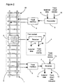
- Figure 2 illustrates a railway track circuit on a track section unit 3 including a detection system according to the present invention.
- the detection system forms a track circuit and contains a track section unit transmitter 5 coupled with the track section unit 3 via a track interface 6 and, at or adjacent the other end of the track section unit 3, a track section unit receiver 7 coupled with the track section unit 3 via a track interface 8.
- the transmitter 5 may receive external data on an input 9 and an indication of the identity of the track section unit on an input 10.
- the receiver 7 receives an indication of track section unit identity on an input 13 and supplies external data on an output 11, and an indication of whether or not the track section unit is clear on an output 12.
- the train-carried equipment 4 comprises a receiver 14 providing external data on an output 15 and an indication of track section unit identity on an output 16.
- said receiver 14 has a structure identical with or similar to that of receiver 7.
- the track section unit transmitter 5 generates a unique signal that is coupled into the track section unit 3 and propagates along the track to receiver 7.
- This signal carries a BPSK modulated message that is repeated on a cyclic basis.
- This message is a digital identification message that contains a track section unit identity, which is unique to that track section unit within a given geographic area.
- Other external data may also be included, e.g. trackside communication information or information to a train on the track circuit.
- the track section unit receiver 7 receives a signal and measures its amplitude and the energy level of the portion of the signal carrying this unique digital identification message. If the portion containing the expected track section unit identity has an amplitude greater than or equal to a threshold set for that particular track section unit and its energy is greater than or equal to a pre-determined minimum proportion of the total energy of the signal, the receiver 7 drives a track section unit clear output.
- the detection system uses a Binary Phase Shift Keying (BPSK) modulation technique.
- BPSK Binary Phase Shift Keying
- This type of PSK modulation technique provides good data rate in the potentially noisy track circuit environment. Thus it allows to transmit high information rate, a part of this information containing track section unit identities that are unique over a large geographic area.
- the information is conveyed by a phase change in a carrier waveform.
- the available range of phase change is 2 ⁇ radians. This range is divided into an even number M of phase transitions, each transition representing a different information data value. Common numbers M of transitions are 2 (Binary), 4 (Quadrature), 8, 16 and 32. The higher the order M of transitions, the higher the error rate for a given signal to noise ratio.
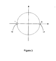
- Figure 3 represents the constellation diagram for Binary PSK modulation technique. It uses two phases 17,18 which are separated by 180°. These two constellation points 17,18 are positioned on the real axis at 0° and 180°, but they may be anywhere as long as they are separated by 180°. This modulation is the most robust of all PSK modulations since it takes serious distortion to make the demodulator reach incorrect decision. As the bandwidth of the signal is limited, this modulation is sufficient, although it is only able to modulate one bit per symbol.
- FIG. 4 illustrates a block diagram of a track section unit transmitter 5 of the detection system.
- the transmitter 5 comprises a BPSK modulation module 20, and, where applicable, a BPSK signal orthogonal addition module 21, a data appending module 22, an internal condition data monitoring module 23 and a DBPSK modulation module 24.
- the BPSK modulation module 20 receives track section unit unique ID on input 10 and converts it into a BPSK signal, using a carrier signal.
- the BPSK signal orthogonal addition module 21 receives this BPSK signal and other differential BPSK (or DBPSK) signals issued from external data. This external data is received via said input 9 by the data appending module 22, which also receives monitoring data from the internal condition data monitoring module 23.
- module 22 is applied to DBPSK modulation module 24 in order to convert this data! in a differential BPSK signal.
- Module 21 receives signals from modules 20 and 24, and adds them orthogonally. The output data of module 22 is then transmitted to each of the two rails of track section unit 3 via track interface 6.
- the BPSK modulation is coherent.
- the use of such a modulation allows a single baseband channel (demodulated signal) to contain all the necessary information needed to determine the amount of received energy that correlates with the expected digital identification message (the expected signal) as well as the total energy of the received signal (the expected signal combined with any unexpected signal and any noise).
- FIG. 5 illustrates a block diagram of a track section unit receiver 7 of the detection system. It should be clear that such a detection system may have more than one such receiver.
- the receiver 7 comprises frequency-limited carrier recovery module 30, a down converter 31, a cross correlation module 32, an energy level measurement module 33, a track section unit clear decision 34, and, where applicable, second down converter31', a DBPSK baseband to data module 35, a data appending module 36 and an internal condition data monitoring module 37.
- Receiver 7 receives a signal from the track section unit 3 via track interface 8. This input signal from the track section unit 3 is transmitted to the frequency-limited carrier recovery module 30 in order to recover the initial carrier signal.
- the down converter 31 receives the recovered carrier signal from module 30 and the input signal from the track section unit 3.
- demodulated BPSK signal which is expected to contain the track section unit unique ID.
- the demodulated BPSK signal is applied to modules 32, 33 and 35.
- the second down converter 31' also receives the recovered carrier signal from module 30 and the input signal from the track section unit 3. These signals are converted to obtain a demodulated DBPSK signal, which is expected to contain the external data.
- the DBPSK baseband to data module 35 allows extracting external data, which was differentially BPSK modulated in transmitter 5.
- the appending data module 36 receives data extracted from the demodulated signal via module 35 and data from the internal condition data monitoring 37. Appended data is then determined in order to obtain external data on output 11.
- the cross-correlation module 32 also receives the expected track section unit unique ID in order to extract the portion of the BPSK demodulated signal carrying the expected track section unit unique ID. Module 32 delivers on its output the energy level of this portion of the BPSK demodulated signal.
- the energy level measurement module 33 determines energy level of the demodulated signal. Module 33 delivers on its output the total energy level of the demodulated signal, including any unexpected signal, for example from a transmitter of another track section unit, and any noise.
- Signals from module 32 and module 33 are applied to track section unit clear decision module 34 in order to determine the absence or presence of a train on the corresponding track section unit 3.
- two operations are achieved.
- the energy value of the portion of the signal carrying the expected track section unit unique ID is compared with a pre-determined minimum proportion of the total received energy value. This minimum proportion value is stored in said module 34. The proportion may be set between 30% and 100% dependent upon the coding scheme used. If the energy value of the portion of the signal carrying the expected track section unit unique ID is greater than or equal to the pre-determined minimum proportion of the! total received energy value, module 34 determines that a track section unit safe decision can be made. Otherwise, module 34 detects that the interfering signal is too high for a safe track section unit decision to be made and indicates an occupied track for the duration of this condition.
- module 34 If module 34 has determined that a track section unit safe decision can be made, the energy value of the portion of the signal carrying the expected track section unit unique ID is compared with a threshold value set for that particular track circuit. This threshold value is stored in module 34. Typical threshold currents will be in the range of 10mA to 200mA. If the energy value of the portion of the signal carrying the expected track section unit unique ID is greater than or equal to said preset threshold value, a track section unit clear decision will be made. Otherwise, a track section unit occupied decision will be made.
- the detection system is able to determine the absence or presence of a train on a track section unit 3 of a track 1 even when high levels of interference are present.
- Figure 6 illustrates a method used by above-mentioned track section unit clear decision module 34 of track section unit receiver 7 to determine the absence or presence of a rail vehicle on track section unit 3.
- the first step 40 consists in comparing the energy value of the portion of the signal carrying the expected track section unit unique ID with a pre-determined minimum proportion of the total received energy value. If said energy value of the portion of the signal carrying the expected track section unit unique ID is greater than or equal to said pre-determined minimum proportion of the total received energy value, there will be a shutdown 41 and a fault indication 42 to indicate that interfering signal is too great for a safe track section unit clear decision to be made. Otherwise a determination of absence or presence of a train on the track section unit 3 will be possible.
- the next step 43 consists in comparing the energy value of the portion of the signal carrying the expected track section unit unique ID with the preset threshold value. If said energy value of the portion of the signal carrying the expected track section unit unique ID is greater than or equal to said preset threshold value, it will be indicated an absence 45 of a rail vehicle on the track section unit 3. Otherwise it will be indicated a presence 44 of a rail vehicle. This method is repeated on a cyclic basis.
- FIG. 7 illustrates a railway track circuit on a track section unit including a detection system according to another embodiment of the present invention.
- Said detection system contains a track section unit transmitter 5 coupled with the track section unit 3 via track interface circuitry 6, a track section unit receiver 7 at the one end of the track section unit 3, coupled with the track section unit 3 via track interface circuitry 8 and, at the other end of said track section unit 3, a track section unit receiver 7' coupled with the track section unit 3 via track interface circuitry 8'.
- the transmitter 5 is therefore! arranged between the two receivers 7,7'.
- the detection system according to this embodiment of the invention allows a single transmitter 5 to drive two track section units or for the length of a single track section unit 3 to be twice that which would otherwise be possible, because of the arrangement of said receivers 7,7'.
- the detection system may replace existing track circuit apparatus world wide, in particular on electric lines with high levels of traction interference and in complex station areas with high risk of false feed from a nearby track circuit.
Landscapes
- Engineering & Computer Science (AREA)
- Mechanical Engineering (AREA)
- Automation & Control Theory (AREA)
- Train Traffic Observation, Control, And Security (AREA)
- Digital Transmission Methods That Use Modulated Carrier Waves (AREA)
Abstract
- a track section unit transmitter (5) generating a BPSK signal that carries a digital message which is transmitted into the track section unit (3) and carries a unique code dependent upon the track section unit (3), and
- at least one track section unit receiver (7) of said BPSK signal, the receiver (7) only indicating that the track section unit (3) is clear having received and demodulated a BPSK signal, found that the correlation of the demodulated BPSK signal with the unique code is greater than or equal to a preset threshold and found that said correlation represents a pre-determined minimum proportion of the total energy of the demodulated BPSK signal.
Description
- The invention relates to a system for detecting the presence or absence of a rail vehicle on a track section unit of a track, comprising a track section unit transmitter and at least a track section unit receiver.
- Track circuits are commonly used as fail-safe means of rail vehicle detection within complete railway signalling systems. For electrified railways these typically consist of an audio-frequency transmitter connected via the tracks to a tuned receiver, which will only indicate the absence of a rail vehicle if the transmitted signal is received. Thus the presence of a rail vehicle on the track will block the transmitted signal. Railways are divided into section units, each section unit having such a transmitter and a tuned receiver to determine the section unit occupied by the train.
- Single audio frequency transmitter systems have two potential unsafe failure modes. On the one hand, track circuits must share the railway track with train traction control systems, which generate a signal at the track circuit frequency. Due to interference, signals from these traction systems can potentially mimic track circuit signals. On the other hand, cross-coupling between tracks may cause a connection to exist between a receiver and a transmitter at the same frequency but on different track circuits. The acceptance of a signal from another track may lead to a false detection.
- These failure modes can be overcome by applying modulation techniques to the track circuit signal. Existing modulation techniques in use on railway track circuits include Frequency Shift Keying (FSK) and Phase Shift Keying (PSK) in order to form a distinct electrical signal that is transmitted along the track. PSK is well known to the communications industry for providing good data rate in potentially noisy track circuit environment conditions. Thus, it makes it possible to develop a signal with some level of uniqueness, which differentiates it from any other track circuit and from the signals generated in the traction return system.
- An apparatus using PSK modulation technique for railway track circuits is known from
US 2003/0112131 . This apparatus may be set on at least one section unit of railway and focuses on a Quadrature Phase Shift Keying (QPSK) modulated signal that carries a digital message including an indication of the identity of the track section unit. A transmitter generates the signal, which is transmitted to the track circuit. A receiver may detect the signal, the receiver only indicating that the track section unit is clear having received a QPSK signal of amplitude greater than a threshold and carrying the correct track section unit identity. Such an apparatus is able to carry enough data to contain unique track identities and to transfer other data external to the track circuit system. Moreover, using a threshold allows the equipment to reliably detect only signals having an amplitude greater than potential noise sources. - Unfortunately, this apparatus uses a fixed threshold in order to make the correct decision about presence of the train or not under most circumstances. Yet, there are many unpredictable situations, which may interfere with the received signal and hence reduce the ability of a simple threshold to make the right decision. In noisy conditions, particularly in presence of interference between several track circuits, the ratio between the signal to be received from the transmitter and noise signals may influence signal detection towards this fixed threshold. Thus, such an apparatus will tend to unreliability when the interfering signal causes too much noise for a safe track section unit clear decision to be made.
- Moreover, QPSK is a complex modulation technique, which requires sophisticated data processing systems.
- There is therefore a need for a simple and robust system for detecting the presence or absence of a rail vehicle on a track section unit of a track, that is able to detect PSK modulating signals in order to make safe track section unit clear decision under whatever circumstances, and more particularly when high levels of interference are present.
- For this purpose, the present invention addresses these problems by providing a system for detecting the presence or absence of a rail vehicle on a track section unit of a track, comprising:
- a track section unit transmitter generating a BPSK signal that carries a digital message which is transmitted into the track section unit and carries a unique code dependent upon the track section unit, and
- at least one track section unit receiver of said BPSK signal, the receiver only indicating that the track section unit is clear having received and demodulated a BPSK signal, found that the correlation of the demodulated BPSK signal with the unique code is greater than or equal to a preset threshold and found that said correlation represents a pre-determined minimum proportion of the total energy of the demodulated BPSK signal.
- This detection system takes a track section unit clear decision only after having met two essential conditions. First, the track section unit receiver has to receive a BPSK signal at least one portion of which carries the expected indication of the identity of the track section unit, this portion being greater than or equal to a preset threshold. Second, the energy of this portion has to be greater than or equal to a pre-determined proportion of the total received energy.
- The energy value of the portion correlated to the expected indication of the identity of the track section unit represents the energy value of the signal from the track section unit transmitter. The total energy of the signal received by the receiver includes the energy value of this portion, as well as those of any unexpected signal from other track circuits and any noise By comparing these two energy values against each other and against a conventional and preset threshold, a highly robust track section unit clear or occupied decision can be made even when high levels of interference are present.
- According to a preferred embodiment of the invention, a coherent BPSK modulation may be used. This will allow the correlation to be implemented with no requirement for synchronisation. The necessary information needed to determine the amount of received energy that correlates with the expected digital information signal will be contained in a single baseband channel.
- By contrast with this preferred embodiment of the invention, the more complex systems of the prior art have to synchronise to the received data, which will not be reliable under high interference conditions, and then measure the received energy symbol by symbol. Even then immunity to interference is not guaranteed as unwanted energy will be mixed with the wanted energy symbol by symbol. Thus detection and response to this situation will be very complex.
- For the purpose of producing a BPSK signal with a high form factor, the BPSK signal may further be constrained to a narrow frequency band.
- The BPSK signal may further be a coherent or a differential (DBPSK) form of a BPSK modulated signal.
- For the purpose of a precise recognition and to avoid ambiguous detection, the pre-determined minimum proportion of the total received energy is combined with a specific subset of code words with a defined minimum distance at all cyclic rotations to be used with said track section unit.
- For the purpose of reducing the level of equipment required and to increase the maximum track circuit length, the detection system may further comprise at least two receivers, each receiver being on an opposite side of the track section unit.
- For the purpose of adapting the system to the track section unit is relied to, the preset threshold may further be set for the track section unit. This threshold may be set for that particular track section unit on the basis of the expected energy level of the signal transmitted by the track section unit transmitter through the particular set of track circuit conditions carrying the indication of the identity of the track section unit.
- According to a further aspect of the invention, there is provided a method for monitoring a system for detecting the presence or absence of a rail vehicle on a track section unit of a track, said system comprising a track section unit transmitter and at least one track section unit receiver, said method comprising:
- generating a BPSK signal that carries a digital message including a unique code dependent upon the track section unit,
- transmitting said BPSK signal into the track section unit,
- receiving a signal from said track section unit,
- demodulating said signal from said track section unit into a demodulated BPSK signal,
- calculating a correlation of said demodulated BPSK signal to the expected unique code,
- only indicating that the track section unit is clear having found that said correlation is greater than or equal to a preset threshold and represents a pre-determined minimum proportion of the total energy of the demodulated BPSK signal.
- According to a preferred embodiment, the method may further comprise:
- determining whether the energy value of the correlation represents a pre-determined minimum proportion of the total energy of the demodulated BPSK signal, and
- if the energy value of the correlation represents a pre-determined minimum proportion of the total energy of the demodulated BPSK signal, then comparing said correlation to the preset threshold.
- If the second condition is met, the detection system will consider that measurement conditions are good enough to make a track section unit safe decision. Otherwise, the detection system will detect that interfering signal is too great for a safe track decision to be made and will indicate an occupied track section unit for the duration of this condition. The first condition will be examined only if the second condition is met. If the first condition is filled, a track section unit clear decision will be made. Otherwise, a track section unit occupied decision will be made.
- A detailed description of examples of implementation of the present invention is provided herein below with reference to the following drawings in which:
-
figure 1 is a schematic illustration of a rail vehicle which may have train-carried equipment on a railway track, -
figure 2 is a schematic illustration of a railway track circuit on a track section unit including a detection system according to the present invention, -
figure 3 is a schematic illustration of a constellation diagram for Binary PSK modulation technique, -
figure 4 is a schematic illustration of a block diagram of a track section unit transmitter of the detection system, -
figure 5 is a schematic illustration of a block diagram of a track section unit receiver of the detection system, -
figure 6 is a schematic illustration of a method used by track section unit decision module of track section unit receiver to determine the absence or presence of a train on track section unit, and -
figure 7 is a schematic illustration of a railway track circuit on a track section unit including a detection system according to another embodiment of the present invention. -
Figure 1 illustrates an example of arail vehicle 2 which may have train-carried equipment on arailway track 1. Railway track circuits with detection systems according to the present invention are used for determining the position of therail vehicle 2. To this end, therailway 1 is divided intrack section units railway track 1. Eachtrack section unit rail vehicle 2 on said track section unit. -
Figure 2 illustrates a railway track circuit on atrack section unit 3 including a detection system according to the present invention. - The detection system forms a track circuit and contains a track
section unit transmitter 5 coupled with thetrack section unit 3 via atrack interface 6 and, at or adjacent the other end of thetrack section unit 3, a tracksection unit receiver 7 coupled with thetrack section unit 3 via atrack interface 8. - The
transmitter 5 may receive external data on aninput 9 and an indication of the identity of the track section unit on aninput 10. Thereceiver 7 receives an indication of track section unit identity on aninput 13 and supplies external data on anoutput 11, and an indication of whether or not the track section unit is clear on anoutput 12. - The train-carried equipment 4 comprises a
receiver 14 providing external data on anoutput 15 and an indication of track section unit identity on anoutput 16. Typically, saidreceiver 14 has a structure identical with or similar to that ofreceiver 7. - The track
section unit transmitter 5 generates a unique signal that is coupled into thetrack section unit 3 and propagates along the track toreceiver 7. This signal carries a BPSK modulated message that is repeated on a cyclic basis. This message is a digital identification message that contains a track section unit identity, which is unique to that track section unit within a given geographic area. Other external data may also be included, e.g. trackside communication information or information to a train on the track circuit. - The track
section unit receiver 7 receives a signal and measures its amplitude and the energy level of the portion of the signal carrying this unique digital identification message. If the portion containing the expected track section unit identity has an amplitude greater than or equal to a threshold set for that particular track section unit and its energy is greater than or equal to a pre-determined minimum proportion of the total energy of the signal, thereceiver 7 drives a track section unit clear output. - The detection system uses a Binary Phase Shift Keying (BPSK) modulation technique. This type of PSK modulation technique provides good data rate in the potentially noisy track circuit environment. Thus it allows to transmit high information rate, a part of this information containing track section unit identities that are unique over a large geographic area.
- The information is conveyed by a phase change in a carrier waveform. The available range of phase change is 2π radians. This range is divided into an even number M of phase transitions, each transition representing a different information data value. Common numbers M of transitions are 2 (Binary), 4 (Quadrature), 8, 16 and 32. The higher the order M of transitions, the higher the error rate for a given signal to noise ratio.
-
Figure 3 represents the constellation diagram for Binary PSK modulation technique. It uses twophases constellation points -
Figure 4 illustrates a block diagram of a tracksection unit transmitter 5 of the detection system. Thetransmitter 5 comprises aBPSK modulation module 20, and, where applicable, a BPSK signalorthogonal addition module 21, adata appending module 22, an internal conditiondata monitoring module 23 and aDBPSK modulation module 24. TheBPSK modulation module 20 receives track section unit unique ID oninput 10 and converts it into a BPSK signal, using a carrier signal. The BPSK signalorthogonal addition module 21 receives this BPSK signal and other differential BPSK (or DBPSK) signals issued from external data. This external data is received via saidinput 9 by thedata appending module 22, which also receives monitoring data from the internal conditiondata monitoring module 23. Then the data output ofmodule 22 is applied toDBPSK modulation module 24 in order to convert this data! in a differential BPSK signal.Module 21 receives signals frommodules module 22 is then transmitted to each of the two rails oftrack section unit 3 viatrack interface 6. - In a preferred embodiment of the invention, the BPSK modulation is coherent. The use of such a modulation allows a single baseband channel (demodulated signal) to contain all the necessary information needed to determine the amount of received energy that correlates with the expected digital identification message (the expected signal) as well as the total energy of the received signal (the expected signal combined with any unexpected signal and any noise).
-
Figure 5 illustrates a block diagram of a tracksection unit receiver 7 of the detection system. It should be clear that such a detection system may have more than one such receiver. Thereceiver 7 comprises frequency-limitedcarrier recovery module 30, adown converter 31, across correlation module 32, an energylevel measurement module 33, a track section unitclear decision 34, and, where applicable, second down converter31', a DBPSK baseband todata module 35, adata appending module 36 and an internal conditiondata monitoring module 37.Receiver 7 receives a signal from thetrack section unit 3 viatrack interface 8. This input signal from thetrack section unit 3 is transmitted to the frequency-limitedcarrier recovery module 30 in order to recover the initial carrier signal. The downconverter 31 receives the recovered carrier signal frommodule 30 and the input signal from thetrack section unit 3. These signals are converted to obtain a demodulated BPSK signal, which is expected to contain the track section unit unique ID. For the purpose of determining the occupation of thetrack section unit 3 by a train, the demodulated BPSK signal is applied tomodules - Where applicable, the second down converter 31' also receives the recovered carrier signal from
module 30 and the input signal from thetrack section unit 3. These signals are converted to obtain a demodulated DBPSK signal, which is expected to contain the external data. The DBPSK baseband todata module 35 allows extracting external data, which was differentially BPSK modulated intransmitter 5. The appendingdata module 36 receives data extracted from the demodulated signal viamodule 35 and data from the internal condition data monitoring 37. Appended data is then determined in order to obtain external data onoutput 11. - The
cross-correlation module 32 also receives the expected track section unit unique ID in order to extract the portion of the BPSK demodulated signal carrying the expected track section unit unique ID.Module 32 delivers on its output the energy level of this portion of the BPSK demodulated signal. - The energy
level measurement module 33 determines energy level of the demodulated signal.Module 33 delivers on its output the total energy level of the demodulated signal, including any unexpected signal, for example from a transmitter of another track section unit, and any noise. - Signals from
module 32 andmodule 33 are applied to track section unitclear decision module 34 in order to determine the absence or presence of a train on the correspondingtrack section unit 3. For this purpose, two operations are achieved. First, the energy value of the portion of the signal carrying the expected track section unit unique ID is compared with a pre-determined minimum proportion of the total received energy value. This minimum proportion value is stored in saidmodule 34. The proportion may be set between 30% and 100% dependent upon the coding scheme used. If the energy value of the portion of the signal carrying the expected track section unit unique ID is greater than or equal to the pre-determined minimum proportion of the! total received energy value,module 34 determines that a track section unit safe decision can be made. Otherwise,module 34 detects that the interfering signal is too high for a safe track section unit decision to be made and indicates an occupied track for the duration of this condition. - If
module 34 has determined that a track section unit safe decision can be made, the energy value of the portion of the signal carrying the expected track section unit unique ID is compared with a threshold value set for that particular track circuit. This threshold value is stored inmodule 34. Typical threshold currents will be in the range of 10mA to 200mA. If the energy value of the portion of the signal carrying the expected track section unit unique ID is greater than or equal to said preset threshold value, a track section unit clear decision will be made. Otherwise, a track section unit occupied decision will be made. - By combining the two above-mentioned operations, the detection system is able to determine the absence or presence of a train on a
track section unit 3 of atrack 1 even when high levels of interference are present. - In a preferred embodiment where the BPSK modulation is coherent and where only a single baseband channel is used, these two operations are simplified. A simple and robust cross-correlation against the expected digital identification message can be used to determine the energy of expected signal, while simple "magnitude-only" addition of the BPSK demodulated signal can be used to determine the total energy of the received signal. By comparing these two energy values against each other and against a pre-determined threshold, a highly robust and noise immune track section unit clear or occupied decision can be made.
-
Figure 6 illustrates a method used by above-mentioned track section unitclear decision module 34 of tracksection unit receiver 7 to determine the absence or presence of a rail vehicle ontrack section unit 3. Thefirst step 40 consists in comparing the energy value of the portion of the signal carrying the expected track section unit unique ID with a pre-determined minimum proportion of the total received energy value. If said energy value of the portion of the signal carrying the expected track section unit unique ID is greater than or equal to said pre-determined minimum proportion of the total received energy value, there will be ashutdown 41 and afault indication 42 to indicate that interfering signal is too great for a safe track section unit clear decision to be made. Otherwise a determination of absence or presence of a train on thetrack section unit 3 will be possible. In this case, thenext step 43 consists in comparing the energy value of the portion of the signal carrying the expected track section unit unique ID with the preset threshold value. If said energy value of the portion of the signal carrying the expected track section unit unique ID is greater than or equal to said preset threshold value, it will be indicated anabsence 45 of a rail vehicle on thetrack section unit 3. Otherwise it will be indicated apresence 44 of a rail vehicle. This method is repeated on a cyclic basis. -
Figure 7 illustrates a railway track circuit on a track section unit including a detection system according to another embodiment of the present invention. Said detection system contains a tracksection unit transmitter 5 coupled with thetrack section unit 3 viatrack interface circuitry 6, a tracksection unit receiver 7 at the one end of thetrack section unit 3, coupled with thetrack section unit 3 viatrack interface circuitry 8 and, at the other end of saidtrack section unit 3, a track section unit receiver 7' coupled with thetrack section unit 3 via track interface circuitry 8'. Thetransmitter 5 is therefore! arranged between the tworeceivers 7,7'. The detection system according to this embodiment of the invention allows asingle transmitter 5 to drive two track section units or for the length of a singletrack section unit 3 to be twice that which would otherwise be possible, because of the arrangement of saidreceivers 7,7'. - The detection system according to above-mentioned embodiments may replace existing track circuit apparatus world wide, in particular on electric lines with high levels of traction interference and in complex station areas with high risk of false feed from a nearby track circuit.
- It is to be understood that the invention is not intended to be restricted to the details of the above embodiments, which are described only by way of example. Various modifications will become apparent to those skilled in the art and are within the scope of this invention, which is defined more particularly by the attached claims.
Claims (9)
- A system for detecting the presence or absence of a rail vehicle (2) on a track section unit (3) of a track (1), comprising:- a track section unit transmitter (5) generating a BPSK signal that carries a digital message which is transmitted into the track section unit (3) and carries a unique code dependent upon the track section unit (3), and- at least one track section unit receiver (7) of said BPSK signal, the receiver (7) only indicating that the track section unit (3) is clear having received and demodulated a BPSK signal, found that the correlation of the demodulated BPSK signal with the unique code is greater than or equal to a preset threshold and found that said correlation represents a pre-determined minimum proportion of the total energy of the demodulated BPSK signal.
- The system of claim 1, wherein the BPSK signal is coherent.
- The system of any of claims 1 and 2, wherein the BPSK signal is constrained to a narrow frequency band.
- The system of any of the preceding claims, wherein the BPSK signal is a differential form (DBPSK) of a BPSK modulated signal.
- The system of any of the preceding claims, wherein said pre-determined minimum proportion of the total received energy is combined with a specific subset of code words with a defined minimum distance at all cyclic rotations to be used with said track section unit (3).
- The system of any of the preceding claims, comprising at least two receivers (7,7'), each receiver (7,7') being on an opposite side of the track section unit (3).
- The system of any of the preceding claims, wherein the preset threshold is set for the track section unit (3).
- A method for monitoring a system for detecting the presence or absence of a rail vehicle (2) on a track section unit (3) of a track (1), said system comprising a track section unit transmitter (5) and at least one track section unit receiver (7), said method comprising:- generating a BPSK signal that carries a digital message including a unique code dependent upon the track section unit (3),- transmitting said BPSK signal into the track section unit (3),- receiving a signal from said track section unit (3),- demodulating said signal from said track section unit (3) into a demodulated BPSK signal,- calculating a correlation of said demodulated BPSK signal to the expected unique code,- only indicating that the track section unit (3) is clear having found that said correlation is greater than or equal to a preset threshold and represents a pre-determined minimum proportion of the total energy of the demodulated BPSK signal.
- The method of claim 8, comprising:- determining whether the energy value of the correlation represents a pre-determined minimum proportion of the total energy of the demodulated BPSK signal, and- if the energy value of the correlation represents a pre-determined minimum proportion of the total energy of the demodulated BPSK signal, then comparing said correlation to the preset threshold.
Priority Applications (5)
| Application Number | Priority Date | Filing Date | Title |
|---|---|---|---|
| ES08290231T ES2347898T3 (en) | 2008-03-11 | 2008-03-11 | SYSTEM AND METHOD OF DETECTION FOR RAILWAY CIRCUITS USING A BPSK MODULATED CODING. |
| EP08290231A EP2100792B1 (en) | 2008-03-11 | 2008-03-11 | Detection system and method for railway track circuits using BPSK modulated coding |
| AT08290231T ATE471857T1 (en) | 2008-03-11 | 2008-03-11 | DETECTION DEVICE AND METHOD FOR TRACK CIRCUIT WITH BPSK MODULATED CODING |
| DE602008001597T DE602008001597D1 (en) | 2008-03-11 | 2008-03-11 | Detection device and method for track circuits with BPSK modulated coding |
| KR1020090019798A KR101431285B1 (en) | 2008-03-11 | 2009-03-09 | Detection system and method for railway track circuits using bpsk modulated coding |
Applications Claiming Priority (1)
| Application Number | Priority Date | Filing Date | Title |
|---|---|---|---|
| EP08290231A EP2100792B1 (en) | 2008-03-11 | 2008-03-11 | Detection system and method for railway track circuits using BPSK modulated coding |
Publications (2)
| Publication Number | Publication Date |
|---|---|
| EP2100792A1 true EP2100792A1 (en) | 2009-09-16 |
| EP2100792B1 EP2100792B1 (en) | 2010-06-23 |
Family
ID=40486871
Family Applications (1)
| Application Number | Title | Priority Date | Filing Date |
|---|---|---|---|
| EP08290231A Not-in-force EP2100792B1 (en) | 2008-03-11 | 2008-03-11 | Detection system and method for railway track circuits using BPSK modulated coding |
Country Status (5)
| Country | Link |
|---|---|
| EP (1) | EP2100792B1 (en) |
| KR (1) | KR101431285B1 (en) |
| AT (1) | ATE471857T1 (en) |
| DE (1) | DE602008001597D1 (en) |
| ES (1) | ES2347898T3 (en) |
Cited By (2)
| Publication number | Priority date | Publication date | Assignee | Title |
|---|---|---|---|---|
| WO2010100054A1 (en) * | 2009-03-02 | 2010-09-10 | Siemens Aktiengesellschaft | Device for detecting the occupied state and the free state of a track section as well as method for operating such a device |
| IT201900014706A1 (en) * | 2019-08-13 | 2021-02-13 | Tecnologie Mecc S R L | METHOD AND APPARATUS FOR DETECTION OF THE PRESENCE OF TRAINS |
Citations (4)
| Publication number | Priority date | Publication date | Assignee | Title |
|---|---|---|---|---|
| WO1991011356A1 (en) * | 1990-01-25 | 1991-08-08 | Eb Signal Ab | Track circuit system |
| US5902341A (en) * | 1996-10-30 | 1999-05-11 | Scientific-Atlanta, Inc. | Method and apparatus to automatically generate a train manifest |
| EP1314627A2 (en) * | 2001-11-21 | 2003-05-28 | Westinghouse Brake And Signal Holdings Limited | Railway track circuits |
| GB2400222A (en) * | 2003-04-01 | 2004-10-06 | Trevor Edwin Clegg | Railway train detection system |
-
2008
- 2008-03-11 DE DE602008001597T patent/DE602008001597D1/en active Active
- 2008-03-11 EP EP08290231A patent/EP2100792B1/en not_active Not-in-force
- 2008-03-11 ES ES08290231T patent/ES2347898T3/en active Active
- 2008-03-11 AT AT08290231T patent/ATE471857T1/en not_active IP Right Cessation
-
2009
- 2009-03-09 KR KR1020090019798A patent/KR101431285B1/en not_active Expired - Fee Related
Patent Citations (5)
| Publication number | Priority date | Publication date | Assignee | Title |
|---|---|---|---|---|
| WO1991011356A1 (en) * | 1990-01-25 | 1991-08-08 | Eb Signal Ab | Track circuit system |
| US5902341A (en) * | 1996-10-30 | 1999-05-11 | Scientific-Atlanta, Inc. | Method and apparatus to automatically generate a train manifest |
| EP1314627A2 (en) * | 2001-11-21 | 2003-05-28 | Westinghouse Brake And Signal Holdings Limited | Railway track circuits |
| US20030112131A1 (en) | 2001-11-21 | 2003-06-19 | Mcallister Lawrence Lawson | Railway track circuits |
| GB2400222A (en) * | 2003-04-01 | 2004-10-06 | Trevor Edwin Clegg | Railway train detection system |
Cited By (3)
| Publication number | Priority date | Publication date | Assignee | Title |
|---|---|---|---|---|
| WO2010100054A1 (en) * | 2009-03-02 | 2010-09-10 | Siemens Aktiengesellschaft | Device for detecting the occupied state and the free state of a track section as well as method for operating such a device |
| IT201900014706A1 (en) * | 2019-08-13 | 2021-02-13 | Tecnologie Mecc S R L | METHOD AND APPARATUS FOR DETECTION OF THE PRESENCE OF TRAINS |
| EP3778347A1 (en) | 2019-08-13 | 2021-02-17 | Tecnologie Meccaniche S.r.l. | Method and apparatus for detecting presence of trains |
Also Published As
| Publication number | Publication date |
|---|---|
| KR20090097801A (en) | 2009-09-16 |
| EP2100792B1 (en) | 2010-06-23 |
| ATE471857T1 (en) | 2010-07-15 |
| KR101431285B1 (en) | 2014-08-20 |
| DE602008001597D1 (en) | 2010-08-05 |
| ES2347898T3 (en) | 2010-11-22 |
Similar Documents
| Publication | Publication Date | Title |
|---|---|---|
| US7017864B2 (en) | Railway track circuits | |
| JP4417851B2 (en) | Transmission / reception device for connecting automobile components to a communication network | |
| EP0899923A1 (en) | Transmission of power control signals in a multicarrier modulation system | |
| CN102754404B (en) | Delay detection circuit and receiving device | |
| EP2337290A2 (en) | Signal processing device and method | |
| US11479279B2 (en) | System and method for protecting a communication between a balise and a guided vehicle from cross-talk | |
| US10093329B2 (en) | Track circuit mechanical joint integrity checker | |
| EP2100792B1 (en) | Detection system and method for railway track circuits using BPSK modulated coding | |
| CN102754405A (en) | Receiving circuit and receiving device | |
| JP2011173486A (en) | Track circuit device | |
| JP2002048862A (en) | Moving body traveling direction detection device | |
| Xiao et al. | Improving collision resolution of superposed LoRa signals using a slot-free decoding scheme | |
| JP3283999B2 (en) | Communication device for train control | |
| Hill | Optimal construction of synchronizable coding for railway track circuit data transmission | |
| JPH08183453A (en) | Train detecting device | |
| CN116112123B (en) | Discrete data transmission method and transmission device | |
| JPH06237275A (en) | Special eye pattern and modulation / demodulation method using special eye pattern | |
| JP4785938B2 (en) | Ground / vehicle information transmission apparatus and ground / vehicle information transmission method | |
| WO2005048551A1 (en) | Blind modulation detection | |
| JP6840357B2 (en) | Information transmission system, ground equipment and on-board equipment | |
| KR101275135B1 (en) | Apparatus and method for transmitting/receiving of additional data in broadband wireless communication system | |
| Koshino et al. | 1A24 Development and Evaluation of Mixed Digital and Analog Signals for Railway Signaling (Electrical-Power) | |
| CN102763390B (en) | Delay detector circuit and receiver apparatus | |
| JPS6162256A (en) | Digital communication device | |
| JPS6355819B2 (en) |
Legal Events
| Date | Code | Title | Description |
|---|---|---|---|
| PUAI | Public reference made under article 153(3) epc to a published international application that has entered the european phase |
Free format text: ORIGINAL CODE: 0009012 |
|
| AK | Designated contracting states |
Kind code of ref document: A1 Designated state(s): AT BE BG CH CY CZ DE DK EE ES FI FR GB GR HR HU IE IS IT LI LT LU LV MC MT NL NO PL PT RO SE SI SK TR |
|
| AX | Request for extension of the european patent |
Extension state: AL BA MK RS |
|
| GRAP | Despatch of communication of intention to grant a patent |
Free format text: ORIGINAL CODE: EPIDOSNIGR1 |
|
| 17P | Request for examination filed |
Effective date: 20091105 |
|
| AKX | Designation fees paid |
Designated state(s): AT BE BG CH CY CZ DE DK EE ES FI FR GB GR HR HU IE IS IT LI LT LU LV MC MT NL NO PL PT RO SE SI SK TR |
|
| GRAS | Grant fee paid |
Free format text: ORIGINAL CODE: EPIDOSNIGR3 |
|
| GRAA | (expected) grant |
Free format text: ORIGINAL CODE: 0009210 |
|
| AK | Designated contracting states |
Kind code of ref document: B1 Designated state(s): AT BE BG CH CY CZ DE DK EE ES FI FR GB GR HR HU IE IS IT LI LT LU LV MC MT NL NO PL PT RO SE SI SK TR |
|
| REG | Reference to a national code |
Ref country code: CH Ref legal event code: EP |
|
| REG | Reference to a national code |
Ref country code: IE Ref legal event code: FG4D |
|
| REF | Corresponds to: |
Ref document number: 602008001597 Country of ref document: DE Date of ref document: 20100805 Kind code of ref document: P |
|
| REG | Reference to a national code |
Ref country code: SE Ref legal event code: TRGR |
|
| REG | Reference to a national code |
Ref country code: NL Ref legal event code: VDEP Effective date: 20100623 |
|
| PG25 | Lapsed in a contracting state [announced via postgrant information from national office to epo] |
Ref country code: NO Free format text: LAPSE BECAUSE OF FAILURE TO SUBMIT A TRANSLATION OF THE DESCRIPTION OR TO PAY THE FEE WITHIN THE PRESCRIBED TIME-LIMIT Effective date: 20100923 Ref country code: LT Free format text: LAPSE BECAUSE OF FAILURE TO SUBMIT A TRANSLATION OF THE DESCRIPTION OR TO PAY THE FEE WITHIN THE PRESCRIBED TIME-LIMIT Effective date: 20100623 |
|
| REG | Reference to a national code |
Ref country code: ES Ref legal event code: FG2A Effective date: 20101110 |
|
| LTIE | Lt: invalidation of european patent or patent extension |
Effective date: 20100623 |
|
| PG25 | Lapsed in a contracting state [announced via postgrant information from national office to epo] |
Ref country code: LV Free format text: LAPSE BECAUSE OF FAILURE TO SUBMIT A TRANSLATION OF THE DESCRIPTION OR TO PAY THE FEE WITHIN THE PRESCRIBED TIME-LIMIT Effective date: 20100623 Ref country code: HR Free format text: LAPSE BECAUSE OF FAILURE TO SUBMIT A TRANSLATION OF THE DESCRIPTION OR TO PAY THE FEE WITHIN THE PRESCRIBED TIME-LIMIT Effective date: 20100623 Ref country code: FI Free format text: LAPSE BECAUSE OF FAILURE TO SUBMIT A TRANSLATION OF THE DESCRIPTION OR TO PAY THE FEE WITHIN THE PRESCRIBED TIME-LIMIT Effective date: 20100623 Ref country code: AT Free format text: LAPSE BECAUSE OF FAILURE TO SUBMIT A TRANSLATION OF THE DESCRIPTION OR TO PAY THE FEE WITHIN THE PRESCRIBED TIME-LIMIT Effective date: 20100623 Ref country code: SI Free format text: LAPSE BECAUSE OF FAILURE TO SUBMIT A TRANSLATION OF THE DESCRIPTION OR TO PAY THE FEE WITHIN THE PRESCRIBED TIME-LIMIT Effective date: 20100623 |
|
| PG25 | Lapsed in a contracting state [announced via postgrant information from national office to epo] |
Ref country code: PL Free format text: LAPSE BECAUSE OF FAILURE TO SUBMIT A TRANSLATION OF THE DESCRIPTION OR TO PAY THE FEE WITHIN THE PRESCRIBED TIME-LIMIT Effective date: 20100623 |
|
| PG25 | Lapsed in a contracting state [announced via postgrant information from national office to epo] |
Ref country code: EE Free format text: LAPSE BECAUSE OF FAILURE TO SUBMIT A TRANSLATION OF THE DESCRIPTION OR TO PAY THE FEE WITHIN THE PRESCRIBED TIME-LIMIT Effective date: 20100623 Ref country code: NL Free format text: LAPSE BECAUSE OF FAILURE TO SUBMIT A TRANSLATION OF THE DESCRIPTION OR TO PAY THE FEE WITHIN THE PRESCRIBED TIME-LIMIT Effective date: 20100623 |
|
| PG25 | Lapsed in a contracting state [announced via postgrant information from national office to epo] |
Ref country code: CY Free format text: LAPSE BECAUSE OF FAILURE TO SUBMIT A TRANSLATION OF THE DESCRIPTION OR TO PAY THE FEE WITHIN THE PRESCRIBED TIME-LIMIT Effective date: 20100623 Ref country code: BE Free format text: LAPSE BECAUSE OF FAILURE TO SUBMIT A TRANSLATION OF THE DESCRIPTION OR TO PAY THE FEE WITHIN THE PRESCRIBED TIME-LIMIT Effective date: 20100623 Ref country code: CZ Free format text: LAPSE BECAUSE OF FAILURE TO SUBMIT A TRANSLATION OF THE DESCRIPTION OR TO PAY THE FEE WITHIN THE PRESCRIBED TIME-LIMIT Effective date: 20100623 Ref country code: SK Free format text: LAPSE BECAUSE OF FAILURE TO SUBMIT A TRANSLATION OF THE DESCRIPTION OR TO PAY THE FEE WITHIN THE PRESCRIBED TIME-LIMIT Effective date: 20100623 Ref country code: RO Free format text: LAPSE BECAUSE OF FAILURE TO SUBMIT A TRANSLATION OF THE DESCRIPTION OR TO PAY THE FEE WITHIN THE PRESCRIBED TIME-LIMIT Effective date: 20100623 Ref country code: IS Free format text: LAPSE BECAUSE OF FAILURE TO SUBMIT A TRANSLATION OF THE DESCRIPTION OR TO PAY THE FEE WITHIN THE PRESCRIBED TIME-LIMIT Effective date: 20101023 |
|
| PG25 | Lapsed in a contracting state [announced via postgrant information from national office to epo] |
Ref country code: IT Free format text: LAPSE BECAUSE OF FAILURE TO SUBMIT A TRANSLATION OF THE DESCRIPTION OR TO PAY THE FEE WITHIN THE PRESCRIBED TIME-LIMIT Effective date: 20100623 |
|
| PG25 | Lapsed in a contracting state [announced via postgrant information from national office to epo] |
Ref country code: DK Free format text: LAPSE BECAUSE OF FAILURE TO SUBMIT A TRANSLATION OF THE DESCRIPTION OR TO PAY THE FEE WITHIN THE PRESCRIBED TIME-LIMIT Effective date: 20100623 |
|
| PLBE | No opposition filed within time limit |
Free format text: ORIGINAL CODE: 0009261 |
|
| STAA | Information on the status of an ep patent application or granted ep patent |
Free format text: STATUS: NO OPPOSITION FILED WITHIN TIME LIMIT |
|
| PG25 | Lapsed in a contracting state [announced via postgrant information from national office to epo] |
Ref country code: GR Free format text: LAPSE BECAUSE OF FAILURE TO SUBMIT A TRANSLATION OF THE DESCRIPTION OR TO PAY THE FEE WITHIN THE PRESCRIBED TIME-LIMIT Effective date: 20100924 |
|
| 26N | No opposition filed |
Effective date: 20110324 |
|
| REG | Reference to a national code |
Ref country code: DE Ref legal event code: R097 Ref document number: 602008001597 Country of ref document: DE Effective date: 20110323 |
|
| PG25 | Lapsed in a contracting state [announced via postgrant information from national office to epo] |
Ref country code: MC Free format text: LAPSE BECAUSE OF NON-PAYMENT OF DUE FEES Effective date: 20110331 |
|
| REG | Reference to a national code |
Ref country code: FR Ref legal event code: ST Effective date: 20111130 |
|
| PG25 | Lapsed in a contracting state [announced via postgrant information from national office to epo] |
Ref country code: MT Free format text: LAPSE BECAUSE OF FAILURE TO SUBMIT A TRANSLATION OF THE DESCRIPTION OR TO PAY THE FEE WITHIN THE PRESCRIBED TIME-LIMIT Effective date: 20100623 |
|
| REG | Reference to a national code |
Ref country code: IE Ref legal event code: MM4A |
|
| PG25 | Lapsed in a contracting state [announced via postgrant information from national office to epo] |
Ref country code: FR Free format text: LAPSE BECAUSE OF NON-PAYMENT OF DUE FEES Effective date: 20110331 Ref country code: IE Free format text: LAPSE BECAUSE OF NON-PAYMENT OF DUE FEES Effective date: 20110311 Ref country code: DE Free format text: LAPSE BECAUSE OF NON-PAYMENT OF DUE FEES Effective date: 20111001 |
|
| REG | Reference to a national code |
Ref country code: DE Ref legal event code: R119 Ref document number: 602008001597 Country of ref document: DE Effective date: 20111001 |
|
| REG | Reference to a national code |
Ref country code: CH Ref legal event code: PL |
|
| PG25 | Lapsed in a contracting state [announced via postgrant information from national office to epo] |
Ref country code: CH Free format text: LAPSE BECAUSE OF NON-PAYMENT OF DUE FEES Effective date: 20120331 Ref country code: LI Free format text: LAPSE BECAUSE OF NON-PAYMENT OF DUE FEES Effective date: 20120331 |
|
| PG25 | Lapsed in a contracting state [announced via postgrant information from national office to epo] |
Ref country code: LU Free format text: LAPSE BECAUSE OF NON-PAYMENT OF DUE FEES Effective date: 20110311 |
|
| PG25 | Lapsed in a contracting state [announced via postgrant information from national office to epo] |
Ref country code: PT Free format text: LAPSE BECAUSE OF NON-PAYMENT OF DUE FEES Effective date: 20100623 |
|
| PG25 | Lapsed in a contracting state [announced via postgrant information from national office to epo] |
Ref country code: BG Free format text: LAPSE BECAUSE OF FAILURE TO SUBMIT A TRANSLATION OF THE DESCRIPTION OR TO PAY THE FEE WITHIN THE PRESCRIBED TIME-LIMIT Effective date: 20100923 Ref country code: TR Free format text: LAPSE BECAUSE OF FAILURE TO SUBMIT A TRANSLATION OF THE DESCRIPTION OR TO PAY THE FEE WITHIN THE PRESCRIBED TIME-LIMIT Effective date: 20100623 |
|
| PG25 | Lapsed in a contracting state [announced via postgrant information from national office to epo] |
Ref country code: HU Free format text: LAPSE BECAUSE OF FAILURE TO SUBMIT A TRANSLATION OF THE DESCRIPTION OR TO PAY THE FEE WITHIN THE PRESCRIBED TIME-LIMIT Effective date: 20100623 |
|
| PGFP | Annual fee paid to national office [announced via postgrant information from national office to epo] |
Ref country code: GB Payment date: 20210324 Year of fee payment: 14 Ref country code: SE Payment date: 20210319 Year of fee payment: 14 |
|
| PGFP | Annual fee paid to national office [announced via postgrant information from national office to epo] |
Ref country code: ES Payment date: 20220527 Year of fee payment: 15 |
|
| GBPC | Gb: european patent ceased through non-payment of renewal fee |
Effective date: 20220311 |
|
| PG25 | Lapsed in a contracting state [announced via postgrant information from national office to epo] |
Ref country code: SE Free format text: LAPSE BECAUSE OF NON-PAYMENT OF DUE FEES Effective date: 20220312 Ref country code: GB Free format text: LAPSE BECAUSE OF NON-PAYMENT OF DUE FEES Effective date: 20220311 |
|
| PG25 | Lapsed in a contracting state [announced via postgrant information from national office to epo] |
Ref country code: ES Free format text: LAPSE BECAUSE OF NON-PAYMENT OF DUE FEES Effective date: 20230312 |
|
| REG | Reference to a national code |
Ref country code: ES Ref legal event code: FD2A Effective date: 20240426 |
|
| PG25 | Lapsed in a contracting state [announced via postgrant information from national office to epo] |
Ref country code: ES Free format text: LAPSE BECAUSE OF NON-PAYMENT OF DUE FEES Effective date: 20230312 |