EP2100715A1 - Method for the production of a bearing carrier and product made with the method - Google Patents
Method for the production of a bearing carrier and product made with the method Download PDFInfo
- Publication number
- EP2100715A1 EP2100715A1 EP08004524A EP08004524A EP2100715A1 EP 2100715 A1 EP2100715 A1 EP 2100715A1 EP 08004524 A EP08004524 A EP 08004524A EP 08004524 A EP08004524 A EP 08004524A EP 2100715 A1 EP2100715 A1 EP 2100715A1
- Authority
- EP
- European Patent Office
- Prior art keywords
- relative
- wheels
- fact
- phase
- pair
- Prior art date
- Legal status (The legal status is an assumption and is not a legal conclusion. Google has not performed a legal analysis and makes no representation as to the accuracy of the status listed.)
- Granted
Links
Images

Classifications
-
- B—PERFORMING OPERATIONS; TRANSPORTING
- B29—WORKING OF PLASTICS; WORKING OF SUBSTANCES IN A PLASTIC STATE IN GENERAL
- B29C—SHAPING OR JOINING OF PLASTICS; SHAPING OF MATERIAL IN A PLASTIC STATE, NOT OTHERWISE PROVIDED FOR; AFTER-TREATMENT OF THE SHAPED PRODUCTS, e.g. REPAIRING
- B29C45/00—Injection moulding, i.e. forcing the required volume of moulding material through a nozzle into a closed mould; Apparatus therefor
- B29C45/14—Injection moulding, i.e. forcing the required volume of moulding material through a nozzle into a closed mould; Apparatus therefor incorporating preformed parts or layers, e.g. injection moulding around inserts or for coating articles
- B29C45/1459—Coating annular articles
-
- B—PERFORMING OPERATIONS; TRANSPORTING
- B29—WORKING OF PLASTICS; WORKING OF SUBSTANCES IN A PLASTIC STATE IN GENERAL
- B29C—SHAPING OR JOINING OF PLASTICS; SHAPING OF MATERIAL IN A PLASTIC STATE, NOT OTHERWISE PROVIDED FOR; AFTER-TREATMENT OF THE SHAPED PRODUCTS, e.g. REPAIRING
- B29C45/00—Injection moulding, i.e. forcing the required volume of moulding material through a nozzle into a closed mould; Apparatus therefor
- B29C45/16—Making multilayered or multicoloured articles
- B29C45/1671—Making multilayered or multicoloured articles with an insert
-
- F—MECHANICAL ENGINEERING; LIGHTING; HEATING; WEAPONS; BLASTING
- F16—ENGINEERING ELEMENTS AND UNITS; GENERAL MEASURES FOR PRODUCING AND MAINTAINING EFFECTIVE FUNCTIONING OF MACHINES OR INSTALLATIONS; THERMAL INSULATION IN GENERAL
- F16C—SHAFTS; FLEXIBLE SHAFTS; ELEMENTS OR CRANKSHAFT MECHANISMS; ROTARY BODIES OTHER THAN GEARING ELEMENTS; BEARINGS
- F16C13/00—Rolls, drums, discs, or the like; Bearings or mountings therefor
- F16C13/006—Guiding rollers, wheels or the like, formed by or on the outer element of a single bearing or bearing unit, e.g. two adjacent bearings, whose ratio of length to diameter is generally less than one
-
- F—MECHANICAL ENGINEERING; LIGHTING; HEATING; WEAPONS; BLASTING
- F16—ENGINEERING ELEMENTS AND UNITS; GENERAL MEASURES FOR PRODUCING AND MAINTAINING EFFECTIVE FUNCTIONING OF MACHINES OR INSTALLATIONS; THERMAL INSULATION IN GENERAL
- F16C—SHAFTS; FLEXIBLE SHAFTS; ELEMENTS OR CRANKSHAFT MECHANISMS; ROTARY BODIES OTHER THAN GEARING ELEMENTS; BEARINGS
- F16C29/00—Bearings for parts moving only linearly
- F16C29/04—Ball or roller bearings
- F16C29/045—Ball or roller bearings having rolling elements journaled in one of the moving parts
-
- F—MECHANICAL ENGINEERING; LIGHTING; HEATING; WEAPONS; BLASTING
- F16—ENGINEERING ELEMENTS AND UNITS; GENERAL MEASURES FOR PRODUCING AND MAINTAINING EFFECTIVE FUNCTIONING OF MACHINES OR INSTALLATIONS; THERMAL INSULATION IN GENERAL
- F16C—SHAFTS; FLEXIBLE SHAFTS; ELEMENTS OR CRANKSHAFT MECHANISMS; ROTARY BODIES OTHER THAN GEARING ELEMENTS; BEARINGS
- F16C35/00—Rigid support of bearing units; Housings, e.g. caps, covers
- F16C35/04—Rigid support of bearing units; Housings, e.g. caps, covers in the case of ball or roller bearings
-
- B—PERFORMING OPERATIONS; TRANSPORTING
- B29—WORKING OF PLASTICS; WORKING OF SUBSTANCES IN A PLASTIC STATE IN GENERAL
- B29C—SHAPING OR JOINING OF PLASTICS; SHAPING OF MATERIAL IN A PLASTIC STATE, NOT OTHERWISE PROVIDED FOR; AFTER-TREATMENT OF THE SHAPED PRODUCTS, e.g. REPAIRING
- B29C45/00—Injection moulding, i.e. forcing the required volume of moulding material through a nozzle into a closed mould; Apparatus therefor
- B29C45/14—Injection moulding, i.e. forcing the required volume of moulding material through a nozzle into a closed mould; Apparatus therefor incorporating preformed parts or layers, e.g. injection moulding around inserts or for coating articles
- B29C45/14065—Positioning or centering articles in the mould
-
- B—PERFORMING OPERATIONS; TRANSPORTING
- B29—WORKING OF PLASTICS; WORKING OF SUBSTANCES IN A PLASTIC STATE IN GENERAL
- B29C—SHAPING OR JOINING OF PLASTICS; SHAPING OF MATERIAL IN A PLASTIC STATE, NOT OTHERWISE PROVIDED FOR; AFTER-TREATMENT OF THE SHAPED PRODUCTS, e.g. REPAIRING
- B29C45/00—Injection moulding, i.e. forcing the required volume of moulding material through a nozzle into a closed mould; Apparatus therefor
- B29C45/17—Component parts, details or accessories; Auxiliary operations
- B29C45/26—Moulds
- B29C45/33—Moulds having transversely, e.g. radially, movable mould parts
-
- B—PERFORMING OPERATIONS; TRANSPORTING
- B29—WORKING OF PLASTICS; WORKING OF SUBSTANCES IN A PLASTIC STATE IN GENERAL
- B29L—INDEXING SCHEME ASSOCIATED WITH SUBCLASS B29C, RELATING TO PARTICULAR ARTICLES
- B29L2031/00—Other particular articles
- B29L2031/04—Bearings
-
- E—FIXED CONSTRUCTIONS
- E05—LOCKS; KEYS; WINDOW OR DOOR FITTINGS; SAFES
- E05D—HINGES OR SUSPENSION DEVICES FOR DOORS, WINDOWS OR WINGS
- E05D15/00—Suspension arrangements for wings
- E05D15/06—Suspension arrangements for wings for wings sliding horizontally more or less in their own plane
- E05D15/0621—Details, e.g. suspension or supporting guides
- E05D15/0626—Details, e.g. suspension or supporting guides for wings suspended at the top
- E05D15/063—Details, e.g. suspension or supporting guides for wings suspended at the top on wheels with fixed axis
Definitions
- the present invention refers to a method for the production of a bearing carrier.
- carriers for sliding doors are made up of a main support body of a substantially flattened shape which is provided with two cylindrical passing housings which are co-axial to respective axes which are parallel to each other, with a connecting element for a pin originating from the sliding door, and with two pairs of wheels mounted at opposite ends of respective rods, which are each inserted inside a relative passing housing.
- the American patent US 4,462,844 describes, for example, a carrier of the type which has been described above and in which, in particular, the support rods of each pair of wheels are inserted inside the passing housings with the additional eventual interposition of a number of rolling bearings in order to reduce friction, and in which the wheels are assembled to the same rods by means of the use of pressure pins which are inserted at the ends of the rods.
- the connecting element is defined by an additional passing housing through the main body and arranged between the two housings of the rods in a direction which is transverse to the two housings themselves.
- the pin once it has been inserted into its own housing, is attributed with, at an own end which is arranged outside the housing, a head which has a diameter which is greater than the diameter of the housing itself in order to impede any unthreading.
- the production of the main body consist of cutting a steel plate in order to produce a tile which is provided with four holes and a shaped semi-cylindrical portion, and the subsequent folding of the tile into a U-shape in such a way as to make the holes coincide two by two in order to define the housings for the rods and in such a way that each shaped portion faces the other shaped portion in order to define the housing for the pin.
- the aim of the present invention is to provide a method for the production of a bearing carrier, which will permit a reduction in the number of steps pertaining to the production of the carrier itself, as well as, in addition, a reduction in the number of the construction elements pertaining to the carrier, and, finally, a more rapid and more efficient procedure in terms of installing the carrier without, however, increasing production costs while producing a carrier which will guarantee a high level of performance in terms of weight as well as in terms of reducing friction.
- a method for the production of a bearing carrier comprising a first production phase for a main body which is provided with two cylindrical passing housings which are co-axial to respective axes which are parallel to each other and with a connecting element for an external pin, and a second production phase for two pairs of wheels which are arranged at the opposite ends of respective rods which are each inserted inside a relative cylindrical passing housing; the method being characterised by the fact that the first production phase and the second production phase are defined by a single injection co-moulding phase of the two pairs of wheels and the respective rods together with the said main body forming each pair of wheels in a single piece with the relative rod which is, however, inserted in rotatable fashion inside the relative cylindrical passing housing.
- a bearing carrier will also be produced, the carrier comprising:
- the number 1 indicates in its entirety a bearing carrier suitable to be used to bear sliding doors (of a well-known kind and which are not illustrated).
- the carrier 1 comprises a main body 2 which is of a substantially flattened shape, and two cylindrical housings 3, which are obtained through the main body 2 transverse to an intermediate plane P of the body 2 itself, and which are co-axial to respective axes 3a which are parallel to each other.
- the carrier 1 comprises a further cylindrical housing 41, which is obtained through the main body 2 at an equal distance from both the housings 3, and which is co-axial to a respective axis 41a which is transverse to the axes 3a and contained in the plane P.
- the carrier 1 comprises an internally threaded body 42, such as, for example, a threaded metallic insert, or a nut, which is embedded by co-moulding inside the main body 2, and which is arranged co-axial to the axis 41a along the housing 41, with which it defines a connecting element 4 for an external pin (which is not illustrated) originating from the sliding door.
- an internally threaded body 42 such as, for example, a threaded metallic insert, or a nut, which is embedded by co-moulding inside the main body 2, and which is arranged co-axial to the axis 41a along the housing 41, with which it defines a connecting element 4 for an external pin (which is not illustrated) originating from the sliding door.
- the carrier 1 comprises a rod 51 for each housing 3 which is rotatably arranged inside each cylindrical housing 3; a pair of wheels 52 which are arranged at the opposite ends of each rod 51, and, for each rod 51, a rolling bearing 53 which is suitable for supporting in rotatable fashion the relative rod 51 inside the relative housing 3.
- Each bearing 53 is co-moulded together with the body 2 and presents an outer race 54 which is arranged in contact with an inner surface 3s of the relative housing 3, an inner race 55 which is arranged inside the outer race 54 and which is co-axial to the relative axis 3a, and a number of rolling bodies 54 which are interposed between the two race 54 and 55.
- Each rod 51 is arranged inside an inner race 55, and presents three cylindrical sectors 55a, which are separated from each other by the same number of radial fissures 55b which are parallel to the relative axis 3a, and which define between them a passing hole 55c which is co-axial to the axis 3a itself and which is connected to the radial fissures 55b themselves.
- Each wheel 52 of each pair of wheels 52 is produced by co-moulding with the relative rod 51 and forms, thus, a single body of plastic material with the rod 51 itself, or rather with the relative three cylindrical sectors 55a.
- each wheel 52 presents a central disk 57 which is transverse to the relative axis 3a and which is arranged laterally to the body 2, and a shaped ring 58 which is integral with the disk 57, and which is made of a single piece together with the relative disk 57 and with the relative three cylindrical sectors 55a of the relative rod 51.
- the body 2 presents a symmetrical structure in relation to the plane P, and is produced by injection co-moulding of plastic material, which, according to necessity, may be similar to or different from the plastic material of the rods 51 of/and the relative pairs of wheels 52.
- the body 2 comprises, in a central position and at an intermediate point between the pairs of wheels 52, a reinforcement ribbing 21 of a rectangular shape which is produced around a cylinder 22 which is co-axial to the axis 41a and incorporates the housing 41 and the nut 42.
- the body 2 also comprises two annular reinforcement ribbings 23, which are obtained around the outer races 54 in order to axially block the races 54 themselves and present, in the embodiment which is shown in the Figures, a respective outer diameter of dimensions which are substantially similar to the dimensions of the outer diameters of the wheels 52.
- FIGURES from 6 to 10 show a mould 100 for the provision of a production method for the carrier 1 which has been described above.
- the mould 100 comprises two shells 101 presenting specular shapes in relation to each other and to an intermediate plane P', which coincides with the plane P of the body 2 once the mould 100 is closed.
- Each shell 101 comprises a base wall 101a which is parallel to the plane P' itself, two greater walls 101b which are transverse to the plane P', two lesser walls 101c which are transverse to the plane P' and to the walls 101b, and an inner indent 102 which is shaped in such a way as to reproduce the external outline of the body 2.
- the mould 10 comprises two groups of pins or blades 103 which are mobile parallel to respective axes 103a which are parallel to a respective 3a and through respective holes 103b, which are obtained through the walls 101a in order to permit the introduction of the pins or blades 103 into the mould 100 and are uniformly distributed around each relative axis 3a.
- Each group of pins or blades 103 presents three pins or blades 103 which are distributed around a relative axis 103a in such a way as to define a support surface 103c, which passes via three outer directors of the pins or blades 103 themselves, and presents an outer dimension which is substantially similar to an inner dimension of the relative inner race 55.
- the mould 100 comprises two cylindrical inserts 141 which are mobile towards and away from each other along an axis 141a which is contained in the plane P' and corresponds to the axis 41a, and, for each axis 103a, four flattened inserts 153 which are mobile parallel to the plane P' by means of respective notches 153a which are obtained in the walls 101b of the shells 101.
- each axis 103a The four inserts 153 of each axis 103a are arranged two by two facing each other and each pair of facing inserts 153 and are arranged opposite the relative axis 103a in relation to the other relative pair of facing inserts 153, while the inserts 153 of each pair of facing inserts 153 are arranged at a distance from one another and along the relative axis 103a substantially equal to a thickness of a bearing 53.
- Each insert 153 presents, at the end which is inserted inside the mould 100, a respective arch 155 which is hollowed out in a semi-cylindrical shape which is suitable for producing, with the arch 155 of the insert 153 which is arranged opposite the relative axis 103a and once that both the inserts 153 are arranged inside the mould 100, a central disk 57 of the relative wheel 52.
- each insert 153 presents a semi-annular indent 156 which is obtained around the relative arch 155 and from the part facing the insert 153 of the relative pair of inserts 153 which are facing each other.
- cylindrical pins 103 are used which produce, for each rod 51, three cylindrical sectors 55a which are centrally connected to each other instead of being separated by relative radial fissures 55b which, instead, are obtained with the equivalent use of blades instead of pins.
- the production of a carrier 1 takes place inside the mould 100 by producing by means of co-moulding the main body 2 with the housings 3 and, still by means of co-moulding, the two pairs of wheels 52 with the relative rods 51.
- the mould 100 is initially kept open with the shells 101 facing each other at a determined distance from each other, and with the inserts 153 inserted into the shells 101 by means of the relative notches 153a.
- the nut 42 is positioned on one of the two cylindrical inserts 141, which are brought nearer to each other along the axis 141a until the point of blocking the nut 42 itself in a determined position along the axis 141a or rather along the axis 41a.
- the shells 101 of the mould 100 are also brought nearer to each other and are closed one against the other determining the blocking and the precise positioning of the bearings 53 due to the effect of the double axial check which is exerted on each of these by each pair of inserts 153 of the relative axis 103a and due to the presence of the three pins 103 inside each inner race 55.
- the closure of the mould 100 determines the creation inside the same mould 100 of three spaces V1, V2, and V3 which are isolated from each other by the inserts 153, which, among other things, are shaped in such a way as to also close and seal the annular space which is comprised between the races 54 and 55 of each bearing 53.
- the space V1 corresponds, in substance, to the volume of the body 2, while the spaces V2 and V3 each correspond to a respective pair of wheels 52 with the relative rods 51.
- the inserts 141 and 153 are first extracted from the mould 100, thus permitting the opening of the shells 101 and the extraction of the carrier 1 which is still being supported by the pins 103.
- the carrier 1 is fixed by means of the connecting element 4 to an external threaded pin originating from a sliding door and is inserted inside a track in order to guide the sliding door in co-operation with other carriers 1.
- the presence of a threaded nut 42 is not strictly necessary since a bushing which may be engaged by a pin of the wheel might be sufficient, but, on the other hand, it makes the operation of installing the carrier 1 extremely speedy and removes the need for the aid of any additional fixing elements.
Landscapes
- Engineering & Computer Science (AREA)
- General Engineering & Computer Science (AREA)
- Mechanical Engineering (AREA)
- Manufacturing & Machinery (AREA)
- Injection Moulding Of Plastics Or The Like (AREA)
- Bearings For Parts Moving Linearly (AREA)
Abstract
Description
- The present invention refers to a method for the production of a bearing carrier.
- It should be pointed out that the present invention will make specific reference - without, however, losing any generality in any way - to a method for the production of a bearing carrier which is suitable for being arranged in sliding doors.
- In general, carriers for sliding doors are made up of a main support body of a substantially flattened shape which is provided with two cylindrical passing housings which are co-axial to respective axes which are parallel to each other, with a connecting element for a pin originating from the sliding door, and with two pairs of wheels mounted at opposite ends of respective rods, which are each inserted inside a relative passing housing.
- The American patent
US 4,462,844 , describes, for example, a carrier of the type which has been described above and in which, in particular, the support rods of each pair of wheels are inserted inside the passing housings with the additional eventual interposition of a number of rolling bearings in order to reduce friction, and in which the wheels are assembled to the same rods by means of the use of pressure pins which are inserted at the ends of the rods. In addition, in the carrier which is described in American patentUS 4,462,844 , the connecting element is defined by an additional passing housing through the main body and arranged between the two housings of the rods in a direction which is transverse to the two housings themselves. The pin, once it has been inserted into its own housing, is attributed with, at an own end which is arranged outside the housing, a head which has a diameter which is greater than the diameter of the housing itself in order to impede any unthreading. - In order, however, to produce a carrier of the kind which has been described above, it is necessary to use a procedure which comprises the effective production of the main support body with the two housings for the rods and with the housing for the pin of the door, the introduction of the rods into each housing, the fixing of the wheels at the ends of the rods and, during the installation phase, the additional fixing of the head at the end of the pin, as well as, in the case that a carrier with a higher level of performance is required, the insertion of rolling bearings inside the housings for the rods.
- In addition, in the specific case of the above-mentioned American patent, the production of the main body consist of cutting a steel plate in order to produce a tile which is provided with four holes and a shaped semi-cylindrical portion, and the subsequent folding of the tile into a U-shape in such a way as to make the holes coincide two by two in order to define the housings for the rods and in such a way that each shaped portion faces the other shaped portion in order to define the housing for the pin.
- It is thus obvious that the operations for producing a bearing carrier in accordance with the method which has been described above are not only laborious and require a high number of steps and components, but do not even conclude with the production of the carrier since further additional interventions are also required during the installation phase.
- The aim of the present invention is to provide a method for the production of a bearing carrier, which will permit a reduction in the number of steps pertaining to the production of the carrier itself, as well as, in addition, a reduction in the number of the construction elements pertaining to the carrier, and, finally, a more rapid and more efficient procedure in terms of installing the carrier without, however, increasing production costs while producing a carrier which will guarantee a high level of performance in terms of weight as well as in terms of reducing friction.
- According to the present invention, a method for the production of a bearing carrier will be provided, the method comprising a first production phase for a main body which is provided with two cylindrical passing housings which are co-axial to respective axes which are parallel to each other and with a connecting element for an external pin, and a second production phase for two pairs of wheels which are arranged at the opposite ends of respective rods which are each inserted inside a relative cylindrical passing housing; the method being characterised by the fact that the first production phase and the second production phase are defined by a single injection co-moulding phase of the two pairs of wheels and the respective rods together with the said main body forming each pair of wheels in a single piece with the relative rod which is, however, inserted in rotatable fashion inside the relative cylindrical passing housing.
- According to the present invention, a bearing carrier will also be produced, the carrier comprising:
- a main body of a substantially flattened shape;
- two cylindrical passing housings through the main body and co-axial to respective axes which are parallel to each other;
- a connecting element for an external pin;
- a rod which is rotatably arranged inside each cylindrical passing housing; and
- a pair of wheels which are arranged at opposite ends of each rod;
- The present invention will now be described with reference to the attached drawings, which illustrate a non-limiting form of embodiment of the present invention, in which:
-
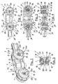
FIGURE 1 illustrates, in perspective view, a preferred form of embodiment of a bearing carrier which is produced according to the present invention; -
FIGURE 2 shows, in lateral elevation and on a reduced scale, the carrier which is shown inFIGURE 1 ; -
FIGURE 3 shows a transverse section of the carrier which is illustrated inFIGURE 2 ; -
FIGURE 4 is a section along the line IV-IV which is shown inFIGURE 2 ; -
FIGURE 5 is a section along the line V-V which is shown inFIGURE 2 ; -
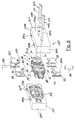
FIGURE 6 illustrates, in a perspective exploded view, the bearing carrier which is shown in the preceding drawing and an injection mould for the production of a preferred form of embodiment of the method according to the present invention; -
FIGURE 7 is a transverse section of the bearing carrier and the injection mould; -
FIGURE 8 is a section along the line VIII-VIII which is shown inFIGURE 7 ; -
FIGURE 9 is a section along the line IX-IX which is shown inFIGURE 7 ; -
FIGURE 10 is a section along the line X-X which is shown inFIGURE 7 . - With reference to
FIGURES 1 - 5 , thenumber 1 indicates in its entirety a bearing carrier suitable to be used to bear sliding doors (of a well-known kind and which are not illustrated). - The
carrier 1 comprises amain body 2 which is of a substantially flattened shape, and twocylindrical housings 3, which are obtained through themain body 2 transverse to an intermediate plane P of thebody 2 itself, and which are co-axial to respective axes 3a which are parallel to each other. In addition, thecarrier 1 comprises a furthercylindrical housing 41, which is obtained through themain body 2 at an equal distance from both thehousings 3, and which is co-axial to arespective axis 41a which is transverse to the axes 3a and contained in the plane P. - In addition, the
carrier 1 comprises an internally threadedbody 42, such as, for example, a threaded metallic insert, or a nut, which is embedded by co-moulding inside themain body 2, and which is arranged co-axial to theaxis 41a along thehousing 41, with which it defines a connecting element 4 for an external pin (which is not illustrated) originating from the sliding door. - Finally, the
carrier 1 comprises arod 51 for eachhousing 3 which is rotatably arranged inside eachcylindrical housing 3; a pair ofwheels 52 which are arranged at the opposite ends of eachrod 51, and, for eachrod 51, arolling bearing 53 which is suitable for supporting in rotatable fashion therelative rod 51 inside therelative housing 3. - Each bearing 53 is co-moulded together with the
body 2 and presents anouter race 54 which is arranged in contact with an inner surface 3s of therelative housing 3, aninner race 55 which is arranged inside theouter race 54 and which is co-axial to the relative axis 3a, and a number ofrolling bodies 54 which are interposed between the tworace - Each
rod 51 is arranged inside aninner race 55, and presents threecylindrical sectors 55a, which are separated from each other by the same number ofradial fissures 55b which are parallel to the relative axis 3a, and which define between them apassing hole 55c which is co-axial to the axis 3a itself and which is connected to theradial fissures 55b themselves. - Each
wheel 52 of each pair ofwheels 52 is produced by co-moulding with therelative rod 51 and forms, thus, a single body of plastic material with therod 51 itself, or rather with the relative threecylindrical sectors 55a. In particular, eachwheel 52 presents acentral disk 57 which is transverse to the relative axis 3a and which is arranged laterally to thebody 2, and ashaped ring 58 which is integral with thedisk 57, and which is made of a single piece together with therelative disk 57 and with the relative threecylindrical sectors 55a of therelative rod 51. - The
body 2 presents a symmetrical structure in relation to the plane P, and is produced by injection co-moulding of plastic material, which, according to necessity, may be similar to or different from the plastic material of therods 51 of/and the relative pairs ofwheels 52. Thebody 2 comprises, in a central position and at an intermediate point between the pairs ofwheels 52, a reinforcement ribbing 21 of a rectangular shape which is produced around acylinder 22 which is co-axial to theaxis 41a and incorporates thehousing 41 and thenut 42. In addition, thebody 2 also comprises twoannular reinforcement ribbings 23, which are obtained around theouter races 54 in order to axially block theraces 54 themselves and present, in the embodiment which is shown in the Figures, a respective outer diameter of dimensions which are substantially similar to the dimensions of the outer diameters of thewheels 52. - The FIGURES from 6 to 10 show a
mould 100 for the provision of a production method for thecarrier 1 which has been described above. - The
mould 100 comprises twoshells 101 presenting specular shapes in relation to each other and to an intermediate plane P', which coincides with the plane P of thebody 2 once themould 100 is closed. Eachshell 101 comprises a base wall 101a which is parallel to the plane P' itself, two greater walls 101b which are transverse to the plane P', twolesser walls 101c which are transverse to the plane P' and to the walls 101b, and aninner indent 102 which is shaped in such a way as to reproduce the external outline of thebody 2. - In addition, the mould 10 comprises two groups of pins or
blades 103 which are mobile parallel to respective axes 103a which are parallel to a respective 3a and through respective holes 103b, which are obtained through the walls 101a in order to permit the introduction of the pins orblades 103 into themould 100 and are uniformly distributed around each relative axis 3a. Each group of pins orblades 103 presents three pins orblades 103 which are distributed around a relative axis 103a in such a way as to define asupport surface 103c, which passes via three outer directors of the pins orblades 103 themselves, and presents an outer dimension which is substantially similar to an inner dimension of the relativeinner race 55. - In addition, the
mould 100 comprises twocylindrical inserts 141 which are mobile towards and away from each other along an axis 141a which is contained in the plane P' and corresponds to theaxis 41a, and, for each axis 103a, fourflattened inserts 153 which are mobile parallel to the plane P' by means of respective notches 153a which are obtained in the walls 101b of theshells 101. - The four
inserts 153 of each axis 103a are arranged two by two facing each other and each pair of facinginserts 153 and are arranged opposite the relative axis 103a in relation to the other relative pair of facinginserts 153, while theinserts 153 of each pair of facinginserts 153 are arranged at a distance from one another and along the relative axis 103a substantially equal to a thickness of abearing 53. - Each
insert 153 presents, at the end which is inserted inside themould 100, arespective arch 155 which is hollowed out in a semi-cylindrical shape which is suitable for producing, with thearch 155 of theinsert 153 which is arranged opposite the relative axis 103a and once that both theinserts 153 are arranged inside themould 100, acentral disk 57 of therelative wheel 52. In addition, eachinsert 153 presents asemi-annular indent 156 which is obtained around therelative arch 155 and from the part facing theinsert 153 of the relative pair ofinserts 153 which are facing each other. - In the form of embodiment which is described in
FIGURES 6-10 ,cylindrical pins 103 are used which produce, for eachrod 51, threecylindrical sectors 55a which are centrally connected to each other instead of being separated by relativeradial fissures 55b which, instead, are obtained with the equivalent use of blades instead of pins. - The production of a
carrier 1 takes place inside themould 100 by producing by means of co-moulding themain body 2 with thehousings 3 and, still by means of co-moulding, the two pairs ofwheels 52 with therelative rods 51. - The
mould 100 is initially kept open with theshells 101 facing each other at a determined distance from each other, and with theinserts 153 inserted into theshells 101 by means of the relative notches 153a. - Before closing the
shells 101 by bringing them nearer to each other, inside themould 100 are also inserted all thepins 103 through the wall 10b of one of the twoshells 101 and on thesurface 103c which is thus formed by each group ofpins 103 is mounted arelative bearing 53 substantially abutting the relative pair ofinserts 153 in correspondence to theindents 156. - At this point, the
nut 42 is positioned on one of the twocylindrical inserts 141, which are brought nearer to each other along the axis 141a until the point of blocking thenut 42 itself in a determined position along the axis 141a or rather along theaxis 41a. Thus theshells 101 of themould 100 are also brought nearer to each other and are closed one against the other determining the blocking and the precise positioning of thebearings 53 due to the effect of the double axial check which is exerted on each of these by each pair ofinserts 153 of the relative axis 103a and due to the presence of the threepins 103 inside eachinner race 55. - The closure of the
mould 100 determines the creation inside thesame mould 100 of three spaces V1, V2, and V3 which are isolated from each other by theinserts 153, which, among other things, are shaped in such a way as to also close and seal the annular space which is comprised between theraces - The space V1 corresponds, in substance, to the volume of the
body 2, while the spaces V2 and V3 each correspond to a respective pair ofwheels 52 with therelative rods 51. - The injection of plastic material into these spaces will determine the production of the elements of the
carrier 1 in rapid fashion and with a decidedly reduced number of pieces in relation to the well-known method. Above all, taking into consideration the extreme precision with which it is possible to produce theshells 101 and thevarious inserts carriers 1 of very precise dimensions while maintaining production at a cost-effective level. - Once injection and cooling have been completed, the
inserts mould 100, thus permitting the opening of theshells 101 and the extraction of thecarrier 1 which is still being supported by thepins 103. - In use, the
carrier 1 is fixed by means of the connecting element 4 to an external threaded pin originating from a sliding door and is inserted inside a track in order to guide the sliding door in co-operation withother carriers 1. The presence of a threadednut 42 is not strictly necessary since a bushing which may be engaged by a pin of the wheel might be sufficient, but, on the other hand, it makes the operation of installing thecarrier 1 extremely speedy and removes the need for the aid of any additional fixing elements. - It is intended that the present invention should not be limited to the forms of embodiment which are herein described and illustrated, which are to be considered as examples of forms of embodiment of the method for the production of a bearing carrier and a bearing carrier itself, which may instead be subject to further modifications relating to the shape and disposition of parts, as well as to details pertaining to construction and assembly.
Claims (11)
- Method for the production of a bearing carrier (1), the method comprising a first production phase for a main body (2) which is provided with two cylindrical passing housings (3) which are co-axial to respective axes which are parallel to each other and with a connecting element (4) for an external pin, and a second production phase for two pairs of wheels (52) which are arranged at the opposite ends of respective rods (51) which are each inserted inside a relative cylindrical passing housing (3); the method being characterised by the fact that the first production phase and the second production phase are defined by a single injection co-moulding phase of the two pairs of wheels (52) and the respective rods (51) together with the said main body (2) forming each pair of wheels (52) in a single piece with the relative rod (51) which is, however, inserted in rotatable fashion inside the relative cylindrical passing housing (3).
- Method according to Claim 1, characterised by the fact that the said co-moulding phase is carried out in an injection mould (100), and is preceded by a phase of insertion into the injection mould (100) itself of a rolling bearing (53) for each pair of wheels (52).
- Method according to Claim 2 characterised by the fact of comprising a phase of blocking each rolling bearing (53) inside the injection mould (100) by means of the insertion of blocking means (103, 153) along each of the said axes and transverse to the axes themselves.
- Method according to Claim 3, characterised by the fact that the insertion of the blocking means (103, 153) inside the said injection mould (100) results in three spaces (V1, V2, V3) which are separate from each other: a first space (V1) corresponds to the main body 2, and a second and third space (V2, V3) correspond to each pair of wheels (52) and the relative rod (51).
- Method according to Claim 4, characterised by the fact that during the injection moulding phase each space of the said three spaces (V1, V2, V3) is injection filled with a respective plastic material.
- Method according to any of the Claims from 2 to 5 whatsoever, characterised by the fact that the said co-moulding phase is carried out in an injection mould (100), and is preceded by a phase of insertion inside the injection mould (100) itself of positioning means (141) through the mould (100) in order to position inside the mould (100) an internally threaded body (42) defining part of the said connecting element (4).
- Method according to Claim 6, characterised by the fact that the said positioning means (141) comprise two cylindrical pins (141) which are mobile towards and away from each other along a connecting axis (141a) which is transverse to the said axes and defines, during the co-moulding phase, a passing housing (41) for the said external pin.
- Bearing carrier (1) comprising:- a main body (2);- two cylindrical passing housings (3) through the main body (2) and co-axial to respective axes (3a) which are parallel to each other;- a connecting element (4) for an external pin;- a rod (51) which is rotatably arranged inside each cylindrical passing housing (3); and- a pair of wheels (52) which are arranged at opposite ends of each rod (51);the carrier (1) being characterised by the fact that each pair of wheels (52) are produced in a single piece and by co-moulding with the relative rods (51) and together with the said main support body (2).
- Bearing carrier according to Claim 8, characterised by the fact that each pair of wheels (52) and the relative rods (51) are made of plastic material.
- Bearing carrier according to Claims 8 or 9, characterised by the fact of comprising a rolling bearing (53) which is inserted between each rod (51) and the relative cylindrical passing housing (3) and co-moulded together with the rod (51) and with the relative cylindrical passing housing (3) themselves.
- Bearing carrier according to Claim 10, characterised by the fact that the connecting element (4) comprises an internally threaded body (42) which is embedded by means of co-moulding inside the main body (2), and a passing housing (41) which is co-axial to a connecting axis (41a) transverse to the said axes (3a) and passing by the internally threaded body (42).
Priority Applications (1)
| Application Number | Priority Date | Filing Date | Title |
|---|---|---|---|
| EP20080004524 EP2100715B1 (en) | 2008-03-12 | 2008-03-12 | Method for the production of a bearing carrier |
Applications Claiming Priority (1)
| Application Number | Priority Date | Filing Date | Title |
|---|---|---|---|
| EP20080004524 EP2100715B1 (en) | 2008-03-12 | 2008-03-12 | Method for the production of a bearing carrier |
Publications (2)
| Publication Number | Publication Date |
|---|---|
| EP2100715A1 true EP2100715A1 (en) | 2009-09-16 |
| EP2100715B1 EP2100715B1 (en) | 2014-01-15 |
Family
ID=39745640
Family Applications (1)
| Application Number | Title | Priority Date | Filing Date |
|---|---|---|---|
| EP20080004524 Active EP2100715B1 (en) | 2008-03-12 | 2008-03-12 | Method for the production of a bearing carrier |
Country Status (1)
| Country | Link |
|---|---|
| EP (1) | EP2100715B1 (en) |
Cited By (1)
| Publication number | Priority date | Publication date | Assignee | Title |
|---|---|---|---|---|
| US9657773B2 (en) * | 2015-08-03 | 2017-05-23 | Ome Technology Co., Ltd. | Linear slide rail and guide wheel seat assembly thereof |
Citations (13)
| Publication number | Priority date | Publication date | Assignee | Title |
|---|---|---|---|---|
| BE473065A (en) * | ||||
| US1351062A (en) * | 1917-05-05 | 1920-08-31 | Allith Prouty Company | Door-hanger |
| GB326802A (en) * | 1928-12-19 | 1930-03-19 | Henderson P C Ltd | Improvements relating to sliding doors, screens and the like |
| US3193870A (en) * | 1963-04-25 | 1965-07-13 | Lawrence Brothers | Truck assembly for sliding doors |
| GB1110288A (en) * | 1965-11-19 | 1968-04-18 | Teleflex Prod Ltd | Improvements in or relating to sliding doors |
| US4109343A (en) * | 1976-05-10 | 1978-08-29 | C. L. Frost & Son, Inc. | Trolley wheel assembly |
| US4462844A (en) | 1981-07-24 | 1984-07-31 | Nippon Steel Corporation | Process for manufacturing hot extruded alloy products |
| US4642844A (en) * | 1985-02-22 | 1987-02-17 | National Manufacturing Co. | Trolley hanger for sliding door |
| US4994222A (en) * | 1988-06-27 | 1991-02-19 | Bridgestone Corporation | Process for producing vulcanized rubber-synthetic resin composite structure |
| JPH05228959A (en) * | 1992-02-24 | 1993-09-07 | Sanshu Mold:Kk | Manufacture of subassembly made of resin |
| WO1999004123A1 (en) * | 1997-07-15 | 1999-01-28 | Geze Gmbh | Automatic door or window system |
| US20010036888A1 (en) * | 1997-03-25 | 2001-11-01 | Ina Walzlager Schaeffler Ohg | Pressure roller for textile machines |
| US20060021192A1 (en) * | 2002-10-17 | 2006-02-02 | Rene Gumbau | Hinge device for a door leaf |
-
2008
- 2008-03-12 EP EP20080004524 patent/EP2100715B1/en active Active
Patent Citations (13)
| Publication number | Priority date | Publication date | Assignee | Title |
|---|---|---|---|---|
| BE473065A (en) * | ||||
| US1351062A (en) * | 1917-05-05 | 1920-08-31 | Allith Prouty Company | Door-hanger |
| GB326802A (en) * | 1928-12-19 | 1930-03-19 | Henderson P C Ltd | Improvements relating to sliding doors, screens and the like |
| US3193870A (en) * | 1963-04-25 | 1965-07-13 | Lawrence Brothers | Truck assembly for sliding doors |
| GB1110288A (en) * | 1965-11-19 | 1968-04-18 | Teleflex Prod Ltd | Improvements in or relating to sliding doors |
| US4109343A (en) * | 1976-05-10 | 1978-08-29 | C. L. Frost & Son, Inc. | Trolley wheel assembly |
| US4462844A (en) | 1981-07-24 | 1984-07-31 | Nippon Steel Corporation | Process for manufacturing hot extruded alloy products |
| US4642844A (en) * | 1985-02-22 | 1987-02-17 | National Manufacturing Co. | Trolley hanger for sliding door |
| US4994222A (en) * | 1988-06-27 | 1991-02-19 | Bridgestone Corporation | Process for producing vulcanized rubber-synthetic resin composite structure |
| JPH05228959A (en) * | 1992-02-24 | 1993-09-07 | Sanshu Mold:Kk | Manufacture of subassembly made of resin |
| US20010036888A1 (en) * | 1997-03-25 | 2001-11-01 | Ina Walzlager Schaeffler Ohg | Pressure roller for textile machines |
| WO1999004123A1 (en) * | 1997-07-15 | 1999-01-28 | Geze Gmbh | Automatic door or window system |
| US20060021192A1 (en) * | 2002-10-17 | 2006-02-02 | Rene Gumbau | Hinge device for a door leaf |
Cited By (1)
| Publication number | Priority date | Publication date | Assignee | Title |
|---|---|---|---|---|
| US9657773B2 (en) * | 2015-08-03 | 2017-05-23 | Ome Technology Co., Ltd. | Linear slide rail and guide wheel seat assembly thereof |
Also Published As
| Publication number | Publication date |
|---|---|
| EP2100715B1 (en) | 2014-01-15 |
Similar Documents
| Publication | Publication Date | Title |
|---|---|---|
| EP0814261B1 (en) | Compressor piston | |
| CN101672329B (en) | Bearing retainer and machining technique thereof | |
| ES2211517T3 (en) | METHOD OF DENSIFICATION OF THE WALL OF AN OPENING IN A SPRAYED METAL PREFORM. | |
| CN201606409U (en) | Integral retainer for cylinder roller bearing | |
| US20140186196A1 (en) | Variable displacement hydraulic motor/pump | |
| CN102537031A (en) | Fluid dynamic bearing device | |
| US2796659A (en) | Bearing making method | |
| EP2100715B1 (en) | Method for the production of a bearing carrier | |
| CN105863918A (en) | Cam follower and method for manufacturing such a cam follower | |
| FI100917B (en) | Procedure for the manufacture of a ball and a ball | |
| US9512877B2 (en) | Linear motion bearing with improved outer housing sleeve | |
| US9964149B2 (en) | Cage for a ball bearing provided with a wire and added interposed parts | |
| EP3164614B1 (en) | Method for producing a cage of a roller bearing | |
| CN105149907B (en) | A kind of guidance method of elastic rolling support roller device and the heavy one-way cylinder plunger of assembly | |
| US20200088237A1 (en) | Method for non-cutting manufacturing of a bearing ring for a rolling bearing and rolling bearing comprising the bearing ring | |
| CN110479928B (en) | Split-type space envelope forming method for large and complex thin-walled special-shaped annular components | |
| WO2014154287A1 (en) | Bearing assembly and method for assembling and mounting said bearing assembly with a component supporting said bearing assembly | |
| EP1972803A1 (en) | Roller bearing and outer ring manufacturing method | |
| CN113090661B (en) | Rings for connecting elements, connecting elements, and corresponding manufacturing methods | |
| CN100376450C (en) | Sliding bearing and motorcycle fork with such sliding bearing | |
| US20220282756A1 (en) | Pivot cradle bearing and method for producing a sychronization device of a pivot cradle bearing | |
| US6109788A (en) | Linear movement ball bearing provided with ball track plates and method for designing ball track plates for such ball bearing | |
| RU2332552C2 (en) | Rock-roller bit bearing structure | |
| CN220015818U (en) | Tapered roller bearing with copper retainer structure | |
| CN217778230U (en) | Integrated hub unit for new energy automobile |
Legal Events
| Date | Code | Title | Description |
|---|---|---|---|
| PUAI | Public reference made under article 153(3) epc to a published international application that has entered the european phase |
Free format text: ORIGINAL CODE: 0009012 |
|
| AK | Designated contracting states |
Kind code of ref document: A1 Designated state(s): AT BE BG CH CY CZ DE DK EE ES FI FR GB GR HR HU IE IS IT LI LT LU LV MC MT NL NO PL PT RO SE SI SK TR |
|
| AX | Request for extension of the european patent |
Extension state: AL BA MK RS |
|
| 17P | Request for examination filed |
Effective date: 20100311 |
|
| 17Q | First examination report despatched |
Effective date: 20100420 |
|
| AKX | Designation fees paid |
Designated state(s): AT BE BG CH CY CZ DE DK EE ES FI FR GB GR HR HU IE IS IT LI LT LU LV MC MT NL NO PL PT RO SE SI SK TR |
|
| GRAP | Despatch of communication of intention to grant a patent |
Free format text: ORIGINAL CODE: EPIDOSNIGR1 |
|
| INTG | Intention to grant announced |
Effective date: 20130813 |
|
| GRAS | Grant fee paid |
Free format text: ORIGINAL CODE: EPIDOSNIGR3 |
|
| GRAA | (expected) grant |
Free format text: ORIGINAL CODE: 0009210 |
|
| AK | Designated contracting states |
Kind code of ref document: B1 Designated state(s): AT BE BG CH CY CZ DE DK EE ES FI FR GB GR HR HU IE IS IT LI LT LU LV MC MT NL NO PL PT RO SE SI SK TR |
|
| REG | Reference to a national code |
Ref country code: GB Ref legal event code: FG4D Ref country code: CH Ref legal event code: EP |
|
| REG | Reference to a national code |
Ref country code: AT Ref legal event code: REF Ref document number: 649596 Country of ref document: AT Kind code of ref document: T Effective date: 20140215 |
|
| REG | Reference to a national code |
Ref country code: IE Ref legal event code: FG4D |
|
| REG | Reference to a national code |
Ref country code: DE Ref legal event code: R096 Ref document number: 602008029888 Country of ref document: DE Effective date: 20140227 |
|
| REG | Reference to a national code |
Ref country code: SE Ref legal event code: TRGR |
|
| REG | Reference to a national code |
Ref country code: NL Ref legal event code: VDEP Effective date: 20140115 |
|
| REG | Reference to a national code |
Ref country code: AT Ref legal event code: MK05 Ref document number: 649596 Country of ref document: AT Kind code of ref document: T Effective date: 20140115 |
|
| REG | Reference to a national code |
Ref country code: LT Ref legal event code: MG4D |
|
| PG25 | Lapsed in a contracting state [announced via postgrant information from national office to epo] |
Ref country code: NO Free format text: LAPSE BECAUSE OF FAILURE TO SUBMIT A TRANSLATION OF THE DESCRIPTION OR TO PAY THE FEE WITHIN THE PRESCRIBED TIME-LIMIT Effective date: 20140415 Ref country code: LT Free format text: LAPSE BECAUSE OF FAILURE TO SUBMIT A TRANSLATION OF THE DESCRIPTION OR TO PAY THE FEE WITHIN THE PRESCRIBED TIME-LIMIT Effective date: 20140115 Ref country code: IS Free format text: LAPSE BECAUSE OF FAILURE TO SUBMIT A TRANSLATION OF THE DESCRIPTION OR TO PAY THE FEE WITHIN THE PRESCRIBED TIME-LIMIT Effective date: 20140515 |
|
| PG25 | Lapsed in a contracting state [announced via postgrant information from national office to epo] |
Ref country code: FI Free format text: LAPSE BECAUSE OF FAILURE TO SUBMIT A TRANSLATION OF THE DESCRIPTION OR TO PAY THE FEE WITHIN THE PRESCRIBED TIME-LIMIT Effective date: 20140115 Ref country code: CY Free format text: LAPSE BECAUSE OF FAILURE TO SUBMIT A TRANSLATION OF THE DESCRIPTION OR TO PAY THE FEE WITHIN THE PRESCRIBED TIME-LIMIT Effective date: 20140115 Ref country code: NL Free format text: LAPSE BECAUSE OF FAILURE TO SUBMIT A TRANSLATION OF THE DESCRIPTION OR TO PAY THE FEE WITHIN THE PRESCRIBED TIME-LIMIT Effective date: 20140115 Ref country code: ES Free format text: LAPSE BECAUSE OF FAILURE TO SUBMIT A TRANSLATION OF THE DESCRIPTION OR TO PAY THE FEE WITHIN THE PRESCRIBED TIME-LIMIT Effective date: 20140115 Ref country code: AT Free format text: LAPSE BECAUSE OF FAILURE TO SUBMIT A TRANSLATION OF THE DESCRIPTION OR TO PAY THE FEE WITHIN THE PRESCRIBED TIME-LIMIT Effective date: 20140115 Ref country code: PT Free format text: LAPSE BECAUSE OF FAILURE TO SUBMIT A TRANSLATION OF THE DESCRIPTION OR TO PAY THE FEE WITHIN THE PRESCRIBED TIME-LIMIT Effective date: 20140515 |
|
| PG25 | Lapsed in a contracting state [announced via postgrant information from national office to epo] |
Ref country code: BE Free format text: LAPSE BECAUSE OF FAILURE TO SUBMIT A TRANSLATION OF THE DESCRIPTION OR TO PAY THE FEE WITHIN THE PRESCRIBED TIME-LIMIT Effective date: 20140115 Ref country code: LV Free format text: LAPSE BECAUSE OF FAILURE TO SUBMIT A TRANSLATION OF THE DESCRIPTION OR TO PAY THE FEE WITHIN THE PRESCRIBED TIME-LIMIT Effective date: 20140115 Ref country code: HR Free format text: LAPSE BECAUSE OF FAILURE TO SUBMIT A TRANSLATION OF THE DESCRIPTION OR TO PAY THE FEE WITHIN THE PRESCRIBED TIME-LIMIT Effective date: 20140115 |
|
| REG | Reference to a national code |
Ref country code: DE Ref legal event code: R097 Ref document number: 602008029888 Country of ref document: DE |
|
| PG25 | Lapsed in a contracting state [announced via postgrant information from national office to epo] |
Ref country code: RO Free format text: LAPSE BECAUSE OF FAILURE TO SUBMIT A TRANSLATION OF THE DESCRIPTION OR TO PAY THE FEE WITHIN THE PRESCRIBED TIME-LIMIT Effective date: 20140115 Ref country code: CZ Free format text: LAPSE BECAUSE OF FAILURE TO SUBMIT A TRANSLATION OF THE DESCRIPTION OR TO PAY THE FEE WITHIN THE PRESCRIBED TIME-LIMIT Effective date: 20140115 Ref country code: LU Free format text: LAPSE BECAUSE OF FAILURE TO SUBMIT A TRANSLATION OF THE DESCRIPTION OR TO PAY THE FEE WITHIN THE PRESCRIBED TIME-LIMIT Effective date: 20140312 Ref country code: EE Free format text: LAPSE BECAUSE OF FAILURE TO SUBMIT A TRANSLATION OF THE DESCRIPTION OR TO PAY THE FEE WITHIN THE PRESCRIBED TIME-LIMIT Effective date: 20140115 Ref country code: DK Free format text: LAPSE BECAUSE OF FAILURE TO SUBMIT A TRANSLATION OF THE DESCRIPTION OR TO PAY THE FEE WITHIN THE PRESCRIBED TIME-LIMIT Effective date: 20140115 |
|
| REG | Reference to a national code |
Ref country code: CH Ref legal event code: PL |
|
| PLBE | No opposition filed within time limit |
Free format text: ORIGINAL CODE: 0009261 |
|
| STAA | Information on the status of an ep patent application or granted ep patent |
Free format text: STATUS: NO OPPOSITION FILED WITHIN TIME LIMIT |
|
| PG25 | Lapsed in a contracting state [announced via postgrant information from national office to epo] |
Ref country code: PL Free format text: LAPSE BECAUSE OF FAILURE TO SUBMIT A TRANSLATION OF THE DESCRIPTION OR TO PAY THE FEE WITHIN THE PRESCRIBED TIME-LIMIT Effective date: 20140115 Ref country code: SK Free format text: LAPSE BECAUSE OF FAILURE TO SUBMIT A TRANSLATION OF THE DESCRIPTION OR TO PAY THE FEE WITHIN THE PRESCRIBED TIME-LIMIT Effective date: 20140115 |
|
| 26N | No opposition filed |
Effective date: 20141016 |
|
| REG | Reference to a national code |
Ref country code: IE Ref legal event code: MM4A |
|
| PG25 | Lapsed in a contracting state [announced via postgrant information from national office to epo] |
Ref country code: IE Free format text: LAPSE BECAUSE OF NON-PAYMENT OF DUE FEES Effective date: 20140312 Ref country code: LI Free format text: LAPSE BECAUSE OF NON-PAYMENT OF DUE FEES Effective date: 20140331 Ref country code: CH Free format text: LAPSE BECAUSE OF NON-PAYMENT OF DUE FEES Effective date: 20140331 |
|
| REG | Reference to a national code |
Ref country code: DE Ref legal event code: R097 Ref document number: 602008029888 Country of ref document: DE Effective date: 20141016 |
|
| PG25 | Lapsed in a contracting state [announced via postgrant information from national office to epo] |
Ref country code: SI Free format text: LAPSE BECAUSE OF FAILURE TO SUBMIT A TRANSLATION OF THE DESCRIPTION OR TO PAY THE FEE WITHIN THE PRESCRIBED TIME-LIMIT Effective date: 20140115 |
|
| PG25 | Lapsed in a contracting state [announced via postgrant information from national office to epo] |
Ref country code: MT Free format text: LAPSE BECAUSE OF FAILURE TO SUBMIT A TRANSLATION OF THE DESCRIPTION OR TO PAY THE FEE WITHIN THE PRESCRIBED TIME-LIMIT Effective date: 20140115 |
|
| REG | Reference to a national code |
Ref country code: FR Ref legal event code: PLFP Year of fee payment: 9 |
|
| PG25 | Lapsed in a contracting state [announced via postgrant information from national office to epo] |
Ref country code: MC Free format text: LAPSE BECAUSE OF FAILURE TO SUBMIT A TRANSLATION OF THE DESCRIPTION OR TO PAY THE FEE WITHIN THE PRESCRIBED TIME-LIMIT Effective date: 20140115 Ref country code: BG Free format text: LAPSE BECAUSE OF FAILURE TO SUBMIT A TRANSLATION OF THE DESCRIPTION OR TO PAY THE FEE WITHIN THE PRESCRIBED TIME-LIMIT Effective date: 20140115 |
|
| PG25 | Lapsed in a contracting state [announced via postgrant information from national office to epo] |
Ref country code: GR Free format text: LAPSE BECAUSE OF FAILURE TO SUBMIT A TRANSLATION OF THE DESCRIPTION OR TO PAY THE FEE WITHIN THE PRESCRIBED TIME-LIMIT Effective date: 20140416 |
|
| PG25 | Lapsed in a contracting state [announced via postgrant information from national office to epo] |
Ref country code: HU Free format text: LAPSE BECAUSE OF FAILURE TO SUBMIT A TRANSLATION OF THE DESCRIPTION OR TO PAY THE FEE WITHIN THE PRESCRIBED TIME-LIMIT; INVALID AB INITIO Effective date: 20080312 Ref country code: TR Free format text: LAPSE BECAUSE OF FAILURE TO SUBMIT A TRANSLATION OF THE DESCRIPTION OR TO PAY THE FEE WITHIN THE PRESCRIBED TIME-LIMIT Effective date: 20140115 |
|
| PG25 | Lapsed in a contracting state [announced via postgrant information from national office to epo] |
Ref country code: IT Free format text: LAPSE BECAUSE OF NON-PAYMENT OF DUE FEES Effective date: 20160312 |
|
| REG | Reference to a national code |
Ref country code: FR Ref legal event code: PLFP Year of fee payment: 10 |
|
| PG25 | Lapsed in a contracting state [announced via postgrant information from national office to epo] |
Ref country code: IT Free format text: LAPSE BECAUSE OF NON-PAYMENT OF DUE FEES Effective date: 20160312 |
|
| PGRI | Patent reinstated in contracting state [announced from national office to epo] |
Ref country code: IT Effective date: 20170710 |
|
| REG | Reference to a national code |
Ref country code: FR Ref legal event code: PLFP Year of fee payment: 11 |
|
| PGFP | Annual fee paid to national office [announced via postgrant information from national office to epo] |
Ref country code: GB Payment date: 20200327 Year of fee payment: 13 |
|
| PGFP | Annual fee paid to national office [announced via postgrant information from national office to epo] |
Ref country code: FR Payment date: 20200326 Year of fee payment: 13 |
|
| GBPC | Gb: european patent ceased through non-payment of renewal fee |
Effective date: 20210312 |
|
| PG25 | Lapsed in a contracting state [announced via postgrant information from national office to epo] |
Ref country code: FR Free format text: LAPSE BECAUSE OF NON-PAYMENT OF DUE FEES Effective date: 20210331 Ref country code: GB Free format text: LAPSE BECAUSE OF NON-PAYMENT OF DUE FEES Effective date: 20210312 |
|
| P01 | Opt-out of the competence of the unified patent court (upc) registered |
Effective date: 20230513 |
|
| PGFP | Annual fee paid to national office [announced via postgrant information from national office to epo] |
Ref country code: SE Payment date: 20260323 Year of fee payment: 19 |
|
| PGFP | Annual fee paid to national office [announced via postgrant information from national office to epo] |
Ref country code: DE Payment date: 20260320 Year of fee payment: 19 |
|
| PGFP | Annual fee paid to national office [announced via postgrant information from national office to epo] |
Ref country code: IT Payment date: 20260320 Year of fee payment: 19 |