EP2100624A1 - A device and a method for disinfecting air - Google Patents
A device and a method for disinfecting air Download PDFInfo
- Publication number
- EP2100624A1 EP2100624A1 EP09397506A EP09397506A EP2100624A1 EP 2100624 A1 EP2100624 A1 EP 2100624A1 EP 09397506 A EP09397506 A EP 09397506A EP 09397506 A EP09397506 A EP 09397506A EP 2100624 A1 EP2100624 A1 EP 2100624A1
- Authority
- EP
- European Patent Office
- Prior art keywords
- wavelength
- process chamber
- radiation
- radiator
- ozone
- Prior art date
- Legal status (The legal status is an assumption and is not a legal conclusion. Google has not performed a legal analysis and makes no representation as to the accuracy of the status listed.)
- Granted
Links
Images


Classifications
-
- F—MECHANICAL ENGINEERING; LIGHTING; HEATING; WEAPONS; BLASTING
- F24—HEATING; RANGES; VENTILATING
- F24F—AIR-CONDITIONING; AIR-HUMIDIFICATION; VENTILATION; USE OF AIR CURRENTS FOR SCREENING
- F24F3/00—Air-conditioning systems in which conditioned primary air is supplied from one or more central stations to distributing units in the rooms or spaces where it may receive secondary treatment; Apparatus specially designed for such systems
- F24F3/12—Air-conditioning systems in which conditioned primary air is supplied from one or more central stations to distributing units in the rooms or spaces where it may receive secondary treatment; Apparatus specially designed for such systems characterised by the treatment of the air otherwise than by heating and cooling
- F24F3/16—Air-conditioning systems in which conditioned primary air is supplied from one or more central stations to distributing units in the rooms or spaces where it may receive secondary treatment; Apparatus specially designed for such systems characterised by the treatment of the air otherwise than by heating and cooling by purification, e.g. by filtering; by sterilisation; by ozonisation
-
- A—HUMAN NECESSITIES
- A61—MEDICAL OR VETERINARY SCIENCE; HYGIENE
- A61L—METHODS OR APPARATUS FOR STERILISING MATERIALS OR OBJECTS IN GENERAL; DISINFECTION, STERILISATION OR DEODORISATION OF AIR; CHEMICAL ASPECTS OF BANDAGES, DRESSINGS, ABSORBENT PADS OR SURGICAL ARTICLES; MATERIALS FOR BANDAGES, DRESSINGS, ABSORBENT PADS OR SURGICAL ARTICLES
- A61L9/00—Disinfection, sterilisation or deodorisation of air
- A61L9/16—Disinfection, sterilisation or deodorisation of air using physical phenomena
- A61L9/18—Radiation
- A61L9/20—Ultraviolet radiation
-
- A—HUMAN NECESSITIES
- A61—MEDICAL OR VETERINARY SCIENCE; HYGIENE
- A61L—METHODS OR APPARATUS FOR STERILISING MATERIALS OR OBJECTS IN GENERAL; DISINFECTION, STERILISATION OR DEODORISATION OF AIR; CHEMICAL ASPECTS OF BANDAGES, DRESSINGS, ABSORBENT PADS OR SURGICAL ARTICLES; MATERIALS FOR BANDAGES, DRESSINGS, ABSORBENT PADS OR SURGICAL ARTICLES
- A61L9/00—Disinfection, sterilisation or deodorisation of air
- A61L9/16—Disinfection, sterilisation or deodorisation of air using physical phenomena
- A61L9/22—Ionisation
Definitions
- the invention relates to the disinfection of air, particularly dry disinfection. More precisely, the invention relates to a dry disinfection device and a method for the disinfection of air.
- a variety of methods can be used for the decontamination of air, including for example UV and filtering methods.
- Ozone or negative ions can be also used for the decontamination of air.
- ionization refers to the production of negative ions in the air.
- these ions are produced e.g. by cosmic radiation, radioactive radiation from the ground, UV light, charging caused by wind friction, electric discharges, combustion, and strong electric fields.
- the lifetime of a negative ion is normally 100 to 1000 seconds.
- Negative ions are decomposed e.g. by such combustion processes in which particles are formed. For example, the smoking of one cigarette may reduce the ion concentration of a room to a level lower than one per mille of the starting level.
- ionization In the decontamination of air based on ionization, reactive oxygen species are supplied into the air to destroy various microorganisms and odorous organic compounds by oxidation.
- the ionization produces such reactive oxygen species which are not harmful to the human body. Consequently, ionization does not involve such concentration limits as ozonization.
- Another advantage of ionization is the negative charging of particles in the air. Thus, the particles accumulate and adhere to surfaces, escaping from the air.
- ozone concentration For people, long-term inhalation of large ozone contents causes damage e.g. in lung tissues, and therefore the ozone concentration must be limited.
- the allowed range for the ozone concentration varies generally from 0.05 ppm to 0.1 ppm.
- high ozone concentrations (1 to 5 ppm) are used, one can stay in such a room only temporarily.
- ozone is a reactive compound that is degraded relatively fast, so that the concentration of 1 ppm will drop to the allowed range in only a few hours, depending on the conditions. Therefore, efficient ozonization that is sufficient for sterilization can be performed, for example, after a working day, in which case the room will be suitable for working on the next day.
- Another alternative is to decompose the ozone catalytically.
- an atomizer By means of an atomizer, even an ozone concentration of 7 ppm will drop to the safe range in about 20 minutes. With appropriate equipment, such ozone decontamination can thus be performed in even the most urgent cases, or in places where e.g. operating theatres or other rooms with hygienic requirements are only vacant for short times.
- the dry disinfection device according to the invention is primarily characterized in what will be presented in the independent claim 1.
- the method according to the invention is, in turn, primarily characterized in what will be presented in the independent claim 10.
- the other, dependent claims will present some preferred embodiments of the invention.
- the second wavelength is longer than 200 nm, preferably 245 to 260 nm. In an embodiment, inter alia, the wavelength of 253.7 nm is used for killing bacteria.
- a large quantity of negative ions is generated into the air.
- superoxide radicals are formed. These superoxide radicals react with aqueous vapour in the air, forming perhydroxyl and hydroxyl radicals.
- ozone is generated into the same air. The production of hydroxyl radicals is accelerated further when the superoxide radicals react with ozone. The production of ozone and negative ions takes place closely in the same room. Thus, the different reactions of ozone and the negative ions take a time that is as long as possible.
- the device according to the invention releases hydroxyl radicals into its environment, as well as advantageously also negative ions and ozone.
- the radicals oxidize organic molecules strongly, thereby decontaminating the air.
- the UV radiation, the negative ions and the ozone also decontaminate the air for their part.
- the forming hydroxyl radicals are among the most antiseptic compounds.
- ozone and the radicals accumulate and decompose the organic compounds they detect, including e.g. odours.
- the odorous substance turns to harmless carbon dioxide, aqueous vapour and oxygen.
- the process chamber further comprises a layer that forms the inner wall of the process chamber and is arranged to reflect the radiation of UV radiators back to an air flow.
- the layer is also arranged to function as a counter electrode for a discharge tip used as an ionizer.
- the device also comprises a power supply arranged to supply electricity to the first UV radiator, the second UV radiator and the discharge tip.
- the device also comprises a frame structure to which the first UV radiator, the second UV radiator and the discharge tip are fixed.
- the frame structure is connected to a cover structure that is used at the process chamber as a lid for the ventilation duct and as a mounting support for the device.
- the dry disinfection solution according to the invention makes very efficient decontamination of air possible even in rooms with people. Furthermore, the dry disinfection solution according to the invention provides many other advantages, including for example:
- UV radiation is electromagnetic radiation.
- the wavelength of UV radiation (100 to 380 nm) is shorter than that of visible light but longer than that of x-rays.
- the short wavelength means that the frequency of UV radiation is high.
- UV radiation is divided into three ranges of radiation, primarily according to its effects on human health and the environment, i.e. its biological effects: UVA radiation (wavelength 315 to 380 nm), UVB radiation (wavelength 280 to 315 nm) and UVC radiation (wavelength 100 to 280 nm).
- UV radiator refers to a device for emitting UV radiation.
- a UV radiator may be a lamp emitting at a UV wavelength. It is also possible to implement the solution so that one UV radiator emits at two or more UV wavelengths. In the examples, however, embodiments will be presented, in which the first UV radiation and the second UV radiation are emitted by separate UV radiators.
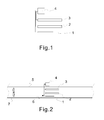
- Figure 1 shows those parts in the structure of a dry disinfection device which have a primary effect on the disinfection of air.
- the figure shows a high-voltage discharge tip used as an ionizer 1, the first UV radiator 2 and the second UV radiator 3.
- the high-voltage discharge tip 1 (or ionizer) is arranged to generate ions.
- the first UV radiator 2 is arranged to emit at a first wavelength (wavelength shorter than 200 nm), which radiation advantageously produces ozone.
- the second UV radiator 3 is arranged to emit at a second wavelength (wavelength longer than 200 nm), which radiation advantageously decontaminates ambient air around the radiator.
- Figure 2 shows the placement of the arrangement of Fig. 1 in a ventilation duct 5.
- a part of the ventilation duct 5 forms a process chamber 6, through which the air to be decontaminated is guided.
- the movement of the air is generated by a fan 7, which is advantageously a fan of a ventilation system.
- the negative ions, OH radicals and ozone are generated inside the process chamber 6.
- the process chamber comprises a high-voltage discharge tip 1 and two ultraviolet radiation sources emitting at different wavelength ranges, i.e. the first UV radiator 2 and the second UV radiator 3.
- Figures 3a, 3b and 3c show an advantageous embodiment of the dry disinfection device.
- Figure 3a shows the cross section of the device, seen from the side direction. In the example, the direction of the air flow is from the left to the right.
- Figure 3b shows the cross-section of the device at line A-A of Fig. 3a.
- Figure 3c illustrates some main components of the device and their placement in the same frame structure 8.
- the device comprises a frame structure 8 to which the first UV radiator 2, the second UV radiator 3 and the ionizer 1 are fixed.
- the device comprises a single power supply 4 arranged to supply electricity to the first UV radiator 2, the second UV radiator 3 and the ionizer 1.
- the cooling ribs 10 of the power supply 4 are placed inside the ventilation duct 5, wherein the cooling of the power supply is efficient and no separate fan is needed in the power supply.
- Figure 5 shows another embodiment, in which the frame structure 8 is placed in the centre of the process chamber 6.
- the frame structure 8 is placed in the centre of the process chamber 6.
- the power supply 4 is also placed in the frame structure 8, wherein it is in an air flow that has an advantageous effect on the cooling of the power supply.
- the power supply 4 may also be on the wall or outside of the process chamber 6, wherein the required energy is supplied by conductors from the power supply to the frame structure 8.
- the solution according to the example is advantageous when large quantities of air are involved. In this case, it is possible to use a process chamber 6 with a large diameter, through which even a large quantity of air can be transferred at reasonable flow rates.
- the walls of the process chamber 6 consist of a ventilation duct 5.
- the shape of the ventilation duct 5 it is possible to affect the air flow rate and thereby the duration of the process.
- the shape of the ventilation duct 5 is expanding at the process.
- the diameter r2 of the process chamber 6 is larger than the diameter r1 of the rest of the duct 5.
- the dimensions of the device constitute an essential factor on the efficiency of the process.
- the device and the process chamber 6 can be suitably dimensioned by employing the following dimensioning rules based on the measurements of the device and the duct and the retention time.
- the retention time of the flow entering the process chamber 6 should preferably be 0.4 to 2 seconds. In locations with mould, for example, the optimal retention time is 0.8 seconds or longer.
- UV light is generated at a power of 20 to 250 W and ionized at a power of 4 to 200 W for each 1 m 3 .
- the ratio between ionization and UV light can be varied according to the use. Other components can also be varied, depending on the problem.
- the frame structure 8 is connected to a kind of a cover structure.
- the cover structure is used at the process chamber 6 as a lid for the ventilation duct 5 and as a mounting support for the device.
- the device can also be taken out of the process chamber 6, for example for maintenance.
- the fans 7 of the ventilation duct are advantageously responsible for generating the air flow, so that no separate fans will be needed in the disinfection device.
- means 11 are provided for measuring the contents of ions, OH radicals and/or ozone, and/or for measuring the quantity of UV radiation. On the basis of the measurement data, the operation of the device is adjusted to keep the values within the desired limit values.
- a control unit 12 can be used for the control.
- the process chamber comprises a UV radiation detector 13, from which the data is transmitted to the outside of the process chamber.
- alarm data is received at an alarm device 14 if the UV radiator 2, 3 stops functioning (for example, the UV lamp goes out).
- the UV radiation detectors 13 for each wavelength to be used, wherein alarm data is obtained on which UV radiator 2, 3 is out of order.
- the damaged UV radiator 2, 3 can also be repaired between periodic inspections.
- the time span between the periodic inspections can be prolonged, and in this way, the total time spent on the periodic inspections is reduced.
- the operation of the device is controlled by monitoring the energy consumption of the device. If the energy consumption deviates from the limit values for a given time, the device is regarded as having been damaged, and an alarm is given. For example, the going out of the UV lamp 2, 3 reduces the energy consumption of the device, which can be detected by measuring. If the energy consumption remains at a low level for a set time, an alarm is given. By using a defined period of time, during which the energy consumption must be outside the limit values, alarms due to temporary power fluctuations are avoided.
- means 16 are provided for removing electrically charged particles from the air flow.
- the device 16 may be an electric diffusion collector with preferably a sufficient electric field for destroying ozone.
- the voltage of the diffusion collector 16 is optimized according to the desired size of particles to be collected.
- the ventilation system may comprise various auxiliary structures 15, as shown in Fig. 5 .
- activated carbon filters honeycombs and/or coarse filters.
- a honeycomb 15 is a cell formed by small parallel channels, through which the air flow is guided.
- the honeycomb 15, which is preferably made of a luminescent material, is placed upstream and/or downstream of the process chamber 6.
- the UV light is reflected within the channels of the honeycomb 15, wherein the particles of the flow are subjected more efficiently to UV radiation.
- the flow can be made laminar or turbulent.
- the flow is made turbulent when entering the process chamber 6.
- the honeycombs 15 are used to make the flow parallel. In an embodiment shown in Fig.
- the ventilation system typically comprises various filters 15, such as coarse filters.
- filters typically in the vicinity of air intake, but they may also be provided elsewhere, such as for example in connection with air outlet, as shown in Fig. 5 .
- the present arrangement provides an efficient way to decontaminate an air flow, and this allows the use of more coarse filters.
- More coarse filters refer to filters which filter larger particles.
- the pressure loss caused by such filters is typically smaller than that caused by finer filters. Consequently, with the presented dry disinfection arrangement, it is possible to use coarse filters with a smaller pressure loss and thereby to achieve the air flow with less work.
Landscapes
- Health & Medical Sciences (AREA)
- Veterinary Medicine (AREA)
- Life Sciences & Earth Sciences (AREA)
- Animal Behavior & Ethology (AREA)
- General Health & Medical Sciences (AREA)
- Public Health (AREA)
- Epidemiology (AREA)
- Engineering & Computer Science (AREA)
- Chemical & Material Sciences (AREA)
- Combustion & Propulsion (AREA)
- Mechanical Engineering (AREA)
- General Engineering & Computer Science (AREA)
- Apparatus For Disinfection Or Sterilisation (AREA)
- Disinfection, Sterilisation Or Deodorisation Of Air (AREA)
Abstract
Description
- The invention relates to the disinfection of air, particularly dry disinfection. More precisely, the invention relates to a dry disinfection device and a method for the disinfection of air.
- A variety of methods can be used for the decontamination of air, including for example UV and filtering methods. Ozone or negative ions can be also used for the decontamination of air.
- In practice, ionization refers to the production of negative ions in the air. In nature, these ions are produced e.g. by cosmic radiation, radioactive radiation from the ground, UV light, charging caused by wind friction, electric discharges, combustion, and strong electric fields. In clean air, the lifetime of a negative ion is normally 100 to 1000 seconds. Negative ions are decomposed e.g. by such combustion processes in which particles are formed. For example, the smoking of one cigarette may reduce the ion concentration of a room to a level lower than one per mille of the starting level.
- In the decontamination of air based on ionization, reactive oxygen species are supplied into the air to destroy various microorganisms and odorous organic compounds by oxidation. The ionization produces such reactive oxygen species which are not harmful to the human body. Consequently, ionization does not involve such concentration limits as ozonization. Another advantage of ionization is the negative charging of particles in the air. Thus, the particles accumulate and adhere to surfaces, escaping from the air.
- Ozone (O3), in turn, is a triatomic form of oxygen with a strongly oxidizing property. In nature, ozone is formed e.g. by the effect of solar UV radiation in the upper atmosphere and, on the earth, for example in connection with lightning strokes. Ozone oxidizes several odorous compounds to an odourless form, and ozone is thus a good deodorizer. Furthermore, even low ozone contents have strong antiseptic properties. Even in small concentrations, ozone is very toxic to all viruses, anaerobic bacteria and fungi. Even low concentrations of only 0.05 ppm may have antiseptic properties in long term if the ozone can be evenly distributed.
- For people, long-term inhalation of large ozone contents causes damage e.g. in lung tissues, and therefore the ozone concentration must be limited. The allowed range for the ozone concentration varies generally from 0.05 ppm to 0.1 ppm. When high ozone concentrations (1 to 5 ppm) are used, one can stay in such a room only temporarily. However, ozone is a reactive compound that is degraded relatively fast, so that the concentration of 1 ppm will drop to the allowed range in only a few hours, depending on the conditions. Therefore, efficient ozonization that is sufficient for sterilization can be performed, for example, after a working day, in which case the room will be suitable for working on the next day. Another alternative is to decompose the ozone catalytically. By means of an atomizer, even an ozone concentration of 7 ppm will drop to the safe range in about 20 minutes. With appropriate equipment, such ozone decontamination can thus be performed in even the most urgent cases, or in places where e.g. operating theatres or other rooms with hygienic requirements are only vacant for short times.
- Various devices have been developed for ozonization. Typically, the ozone is produced by UV light and distributed in the room by a fan.
- It is an aim of the solution according to the invention to present a new air disinfection solution that is easy to install.
- It is an aim of the present invention to provide a system that is easily integrated in a ventilation system and that is also efficient.
- To achieve this aim, the dry disinfection device according to the invention is primarily characterized in what will be presented in the
independent claim 1. The method according to the invention is, in turn, primarily characterized in what will be presented in theindependent claim 10. The other, dependent claims will present some preferred embodiments of the invention. - The invention is based on the idea that air is disinfected by UV radiation, ozonization, ionization, and hydroxyl radicals (OH radicals) simultaneously. The basic idea of the invention is to provide a dry disinfection device whose operation is based on UV radiation, ozonization, ionization and hydroxyl radicals (OH radicals).
- The dry disinfection device according to the invention comprises at least a process chamber that comprises at least a UV radiator arranged to emit at a first wavelength and arranged to produce ozone, as well as an ionizer arranged to generate ions. Furthermore, the process chamber comprises a UV radiator arranged to emit at a second wavelength and arranged to decontaminate air by UV radiation. In an embodiment, the walls of the process chamber are formed of a ventilation duct.
- In an embodiment, the first wavelength is shorter than 200 nm, preferably 180 to 190 nm. In an embodiment, the wavelength of 185 nm is used for ozone production.
- In an embodiment, the second wavelength is longer than 200 nm, preferably 245 to 260 nm. In an embodiment, inter alia, the wavelength of 253.7 nm is used for killing bacteria.
- In the solution according to the invention, a large quantity of negative ions is generated into the air. Upon an impact of oxygen atoms and the negative ions, superoxide radicals are formed. These superoxide radicals react with aqueous vapour in the air, forming perhydroxyl and hydroxyl radicals. Also according to the invention, ozone is generated into the same air. The production of hydroxyl radicals is accelerated further when the superoxide radicals react with ozone. The production of ozone and negative ions takes place closely in the same room. Thus, the different reactions of ozone and the negative ions take a time that is as long as possible. The device according to the invention releases hydroxyl radicals into its environment, as well as advantageously also negative ions and ozone. The radicals oxidize organic molecules strongly, thereby decontaminating the air. The UV radiation, the negative ions and the ozone also decontaminate the air for their part. The forming hydroxyl radicals are among the most antiseptic compounds. For example in a deodorizing process, ozone and the radicals accumulate and decompose the organic compounds they detect, including e.g. odours. In the oxidizing reaction, the odorous substance turns to harmless carbon dioxide, aqueous vapour and oxygen.
- In an embodiment, the process chamber further comprises a layer that forms the inner wall of the process chamber and is arranged to reflect the radiation of UV radiators back to an air flow. In an embodiment, the layer is also arranged to function as a counter electrode for a discharge tip used as an ionizer.
- In an embodiment, the device also comprises a power supply arranged to supply electricity to the first UV radiator, the second UV radiator and the discharge tip.
- In an embodiment, the device also comprises a frame structure to which the first UV radiator, the second UV radiator and the discharge tip are fixed. In an embodiment, the frame structure is connected to a cover structure that is used at the process chamber as a lid for the ventilation duct and as a mounting support for the device.
- The different embodiments of the above-described arrangement, taken separately and in various combinations, provide several advantages. In one embodiment, a significant advantage lies in the fact that it can be easily installed as a part of the ventilation system of a building, even in existing systems.
- The dry disinfection solution according to the invention makes very efficient decontamination of air possible even in rooms with people. Furthermore, the dry disinfection solution according to the invention provides many other advantages, including for example:
- the decomposition and elimination of harmful particles and volatile organic compounds, and their conversion to a harmless form,
- the elimination of odours,
- the inactivation of microbes,
- low energy costs,
- minimized accumulation of particles onto surfaces,
- no production of harmful reactants or side products.
- In the following, the invention will be described in more detail with reference to the appended basic drawings, in which
- Fig. 1
- shows the main components of the structure of a dry disinfection device,
- Fig. 2
- shows the placement of the arrangement of
Fig. 1 in a ventilation duct, - Figs. 3a, 3b and 3c
- show an advantageous embodiment of the dry disinfection device,
- Figs. 4a, 4b and 4c
- show another advantageous embodiment of the dry disinfection device,
- Fig. 5
- shows a third embodiment of the dry disinfection device,
- Fig. 6
- shows a fourth embodiment of the dry disinfection device.
- For the sake of clarity, the drawings only show the details necessary for understanding the invention. The structures and details that are not necessary for understanding the invention but are obvious for anyone skilled in the art have been omitted in the figures in order to emphasize the characteristics of the invention.
- Ultraviolet radiation, or more briefly UV radiation, is electromagnetic radiation. The wavelength of UV radiation (100 to 380 nm) is shorter than that of visible light but longer than that of x-rays. The short wavelength means that the frequency of UV radiation is high. UV radiation is divided into three ranges of radiation, primarily according to its effects on human health and the environment, i.e. its biological effects: UVA radiation (wavelength 315 to 380 nm), UVB radiation (wavelength 280 to 315 nm) and UVC radiation (wavelength 100 to 280 nm).
- In this description, the term UV radiator refers to a device for emitting UV radiation. For example, a UV radiator may be a lamp emitting at a UV wavelength. It is also possible to implement the solution so that one UV radiator emits at two or more UV wavelengths. In the examples, however, embodiments will be presented, in which the first UV radiation and the second UV radiation are emitted by separate UV radiators.
-
Figure 1 shows those parts in the structure of a dry disinfection device which have a primary effect on the disinfection of air. The figure shows a high-voltage discharge tip used as anionizer 1, thefirst UV radiator 2 and thesecond UV radiator 3. The high-voltage discharge tip 1 (or ionizer) is arranged to generate ions. Thefirst UV radiator 2 is arranged to emit at a first wavelength (wavelength shorter than 200 nm), which radiation advantageously produces ozone. Thesecond UV radiator 3 is arranged to emit at a second wavelength (wavelength longer than 200 nm), which radiation advantageously decontaminates ambient air around the radiator. Theionizer 1 and theUV radiators power supply 4 to supply theionizer 1 and theUV radiators -
Figure 2 shows the placement of the arrangement ofFig. 1 in aventilation duct 5. A part of theventilation duct 5 forms aprocess chamber 6, through which the air to be decontaminated is guided. The movement of the air is generated by afan 7, which is advantageously a fan of a ventilation system. The negative ions, OH radicals and ozone are generated inside theprocess chamber 6. For this reason, it is advantageous to use at least twoultraviolet radiation sources ionizer 1. In the example, the process chamber comprises a high-voltage discharge tip 1 and two ultraviolet radiation sources emitting at different wavelength ranges, i.e. thefirst UV radiator 2 and thesecond UV radiator 3. - The wavelength of the radiation from the first UV radiator 2 (the first wavelength) is advantageously shorter than 200 nm, preferably 180 to 190 nm, and the wavelength of the radiation from the second UV radiator 3 (the second wavelength) is longer than 200 nm, preferably 245 to 260 nm. In an embodiment, the wavelength of 185 nm is used for ozone production and the wavelength of 253.7 nm e.g. for killing bacteria.
-
Figures 3a, 3b and 3c show an advantageous embodiment of the dry disinfection device.Figure 3a shows the cross section of the device, seen from the side direction. In the example, the direction of the air flow is from the left to the right.Figure 3b shows the cross-section of the device at line A-A ofFig. 3a. Figure 3c illustrates some main components of the device and their placement in thesame frame structure 8. In the example, the device comprises aframe structure 8 to which thefirst UV radiator 2, thesecond UV radiator 3 and theionizer 1 are fixed. - The
ionizer 1 can be placed entirely in theprocess chamber 6, as in the examples above. It is also possible to place theionizer 1 in such a way that the ions are introduced in theprocess chamber 6 from the outside of the actual process chamber. For example, the ion generating unit of the ionizer may be placed outside theprocess chamber 6, and the ions are led from the ion generating unit into the process chamber in a suitable way. -
Figures 4a, 4b and 4c show an advantageous embodiment of another dry disinfection device.Figure 4a shows the cross section of the device, seen from the side direction. In the example, the direction of the air flow is also from the left to the right.Figure 4b shows the cross-section of the device at line B-B ofFig. 4a. Figure 4c illustrates some main components of the device and their placement in thesame frame structure 8. In the example, thefirst UV radiator 2, thesecond UV radiator 3 and theionizer 1 are fixed to theframe structure 8 which is placed in the centre of theprocess chamber 6. In this way, air flows substantially all around theframe structure 6. In the example, there are two first UV radiators 2 (in the example, UV lamps) and two UV radiators 3 (in the example, UV lamps). Theionizer 1, in turn, is placed at the end of the frame structure 8 (in the example, at the end from which air flows into the process chamber 6). - In the embodiment of
Figs. 4a, 4b and 4c , theprocess chamber 6 further comprises a reflectinglayer 9 that forms the inner wall of the process chamber and is arranged to reflect the radiation of theUV radiators layer 9 is also arranged to function as a counter electrode for thedischarge tip 1 used as an ionizer. - Preferably, the device comprises a
single power supply 4 arranged to supply electricity to thefirst UV radiator 2, thesecond UV radiator 3 and theionizer 1. In the example shown inFigs. 4a and 4b , the coolingribs 10 of thepower supply 4 are placed inside theventilation duct 5, wherein the cooling of the power supply is efficient and no separate fan is needed in the power supply. -
Figure 5 , in turn, shows another embodiment, in which theframe structure 8 is placed in the centre of theprocess chamber 6. In the example, there are twofirst UV radiators 2 and twosecond UV radiators 3. There are twoionizers 1, and they are placed at each end of theframe structure 8. In the example, thepower supply 4 is also placed in theframe structure 8, wherein it is in an air flow that has an advantageous effect on the cooling of the power supply. Thepower supply 4 may also be on the wall or outside of theprocess chamber 6, wherein the required energy is supplied by conductors from the power supply to theframe structure 8. The solution according to the example is advantageous when large quantities of air are involved. In this case, it is possible to use aprocess chamber 6 with a large diameter, through which even a large quantity of air can be transferred at reasonable flow rates. - In the examples of
Figs. 2 ,3a, 3b, 3c ,4a, 4b, 4c , and5 , the walls of theprocess chamber 6 consist of aventilation duct 5. By the shape of theventilation duct 5 it is possible to affect the air flow rate and thereby the duration of the process. In the embodiment shown inFig. 5 , the shape of theventilation duct 5 is expanding at the process. In other words, the diameter r2 of theprocess chamber 6 is larger than the diameter r1 of the rest of theduct 5. By increasing the diameter r2 of theprocess chamber 6, the air flow rate in the process chamber is reduced and the disinfection process becomes more efficient. - The dimensions of the device constitute an essential factor on the efficiency of the process. For example, the device and the
process chamber 6 can be suitably dimensioned by employing the following dimensioning rules based on the measurements of the device and the duct and the retention time. - L = length of the process chamber
- V = rate of the air flowing in the tube size to be connected
- A = cross-sectional area in the process chamber per cross-sectional area in the duct, to which the device is coupled
- The retention time of the flow entering the
process chamber 6 should preferably be 0.4 to 2 seconds. In locations with mould, for example, the optimal retention time is 0.8 seconds or longer. In an advantageous embodiment, UV light is generated at a power of 20 to 250 W and ionized at a power of 4 to 200 W for each 1 m3. The ratio between ionization and UV light can be varied according to the use. Other components can also be varied, depending on the problem. - In an advantageous embodiment, the
frame structure 8 is connected to a kind of a cover structure. The cover structure is used at theprocess chamber 6 as a lid for theventilation duct 5 and as a mounting support for the device. Thus, by opening the lid, the device can also be taken out of theprocess chamber 6, for example for maintenance. - In the embodiments shown as examples, the
fans 7 of the ventilation duct are advantageously responsible for generating the air flow, so that no separate fans will be needed in the disinfection device. - In an advantageous embodiment, such as the example of
Fig. 4a , means 11 are provided for measuring the contents of ions, OH radicals and/or ozone, and/or for measuring the quantity of UV radiation. On the basis of the measurement data, the operation of the device is adjusted to keep the values within the desired limit values. For example, acontrol unit 12 can be used for the control. - In an advantageous embodiment, such as the example of
Fig. 5 , the process chamber comprises aUV radiation detector 13, from which the data is transmitted to the outside of the process chamber. In this case, alarm data is received at analarm device 14 if theUV radiator UV radiation detectors 13 for each wavelength to be used, wherein alarm data is obtained on whichUV radiator UV radiator - In an advantageous embodiment, the operation of the device is controlled by monitoring the energy consumption of the device. If the energy consumption deviates from the limit values for a given time, the device is regarded as having been damaged, and an alarm is given. For example, the going out of the
UV lamp - In an advantageous embodiment, such as in the example of
Fig. 6 , means 16 are provided for removing electrically charged particles from the air flow. For example, thedevice 16 may be an electric diffusion collector with preferably a sufficient electric field for destroying ozone. Preferably, the voltage of thediffusion collector 16 is optimized according to the desired size of particles to be collected. - Furthermore, the ventilation system may comprise various
auxiliary structures 15, as shown inFig. 5 . For example, it is possible to use activated carbon filters, honeycombs and/or coarse filters. Ahoneycomb 15 is a cell formed by small parallel channels, through which the air flow is guided. Thehoneycomb 15, which is preferably made of a luminescent material, is placed upstream and/or downstream of theprocess chamber 6. Thus, the UV light is reflected within the channels of thehoneycomb 15, wherein the particles of the flow are subjected more efficiently to UV radiation. By a suitable design of thehoneycombs 15, the flow can be made laminar or turbulent. In an advantageous embodiment, the flow is made turbulent when entering theprocess chamber 6. Preferably, thehoneycombs 15 are used to make the flow parallel. In an embodiment shown inFig. 5 , the two auxiliary structures indicated with thereference numeral 15 on the right-hand side are honeycombs, and the structure on the left-hand side is an activated carbon filter. With the activated carbon filter, the residue of the decontamination by negative ions, OH radicals and ozone can be effectively collected. - Furthermore, the ventilation system typically comprises
various filters 15, such as coarse filters. Typically, there are filters in the vicinity of air intake, but they may also be provided elsewhere, such as for example in connection with air outlet, as shown inFig. 5 . The present arrangement provides an efficient way to decontaminate an air flow, and this allows the use of more coarse filters. More coarse filters refer to filters which filter larger particles. The pressure loss caused by such filters is typically smaller than that caused by finer filters. Consequently, with the presented dry disinfection arrangement, it is possible to use coarse filters with a smaller pressure loss and thereby to achieve the air flow with less work. - By combining, in various ways, the modes and structures disclosed in connection with the different embodiments of the invention presented above, it is possible to produce various embodiments of the invention in accordance with the spirit of the invention. Therefore, the above- presented examples must not be interpreted as restrictive to the invention, but the embodiments of the invention may be freely varied within the scope of the inventive features presented in the claims hereinbelow.

Claims (11)
- A dry disinfection device for disinfecting air, the device comprising at least- a process chamber comprising at least a UV radiator arranged to emit at a first wavelength and arranged to produce ozone, the process chamber further comprising a UV radiator arranged to emit at a second wavelength, which second wavelength is different from the first wavelength;- an ionizer arranged to generate ions for the process chamber,characterized in that the device further comprises a diffusion collector.
- The dry disinfection device according to claim 1, characterized in that the process chamber further comprises a layer that forms the inner wall of the process chamber and is arranged to reflect UV radiation back to a medium flow.
- The dry disinfection device according to claim 2, characterized in that the ionizer is a high-voltage discharge tip and the layer is also arranged to function as a counter electrode for the discharge tip.
- The dry disinfection device according to any of the preceding claims,
characterized in that the device comprises a first UV radiator arranged to emit at a first wavelength, and a second UV radiator arranged to emit at a second wavelength. - The dry disinfection device according to claim 4, characterized in that the device also comprises a power supply arranged to supply electricity to the first UV radiator, the second UV radiator and the ionizer.
- The dry disinfection device according to claim 4 or 5, characterized in that the device further comprises a frame structure, to which the first UV radiator, the second UV radiator and the ionizer are fixed.
- The dry disinfection device according to any of the preceding claims,
characterized in that the first wavelength is shorter than 200 nm. - The dry disinfection device according to any of the preceding claims,
characterized in that the first wavelength is longer than 200 nm. - The dry disinfection device according to any of the preceding claims,
characterized in that the walls of the process chamber consist of a ventilation duct. - A method for decontaminating air, in which method- ozone is produced by first UV radiation,- second UV radiation is emitted, the wavelength of the radiation being longer than the wavelength of the first radiation,- ions are produced with an ionizer,- OH radicals are produced,characterized in that after a treatment with the UV radiation, ozone, ions and OH radicals, particles are removed from the air flow by a diffusion collector.
the ozone, the ions and the OH radicals are produced into a process chamber which is part of a ventilation duct, - The method according to claim 10, characterized in that the wavelength of the first radiation is shorter than 200 nm and the wavelength of the second radiation is longer than 200 nm.
Applications Claiming Priority (1)
| Application Number | Priority Date | Filing Date | Title |
|---|---|---|---|
| FI20085224A FI20085224L (en) | 2008-03-14 | 2008-03-14 | Apparatus and method for disinfecting air |
Publications (2)
| Publication Number | Publication Date |
|---|---|
| EP2100624A1 true EP2100624A1 (en) | 2009-09-16 |
| EP2100624B1 EP2100624B1 (en) | 2019-10-09 |
Family
ID=39269520
Family Applications (1)
| Application Number | Title | Priority Date | Filing Date |
|---|---|---|---|
| EP09397506.8A Active EP2100624B1 (en) | 2008-03-14 | 2009-03-12 | Device and method for disinfecting air |
Country Status (2)
| Country | Link |
|---|---|
| EP (1) | EP2100624B1 (en) |
| FI (1) | FI20085224L (en) |
Cited By (13)
| Publication number | Priority date | Publication date | Assignee | Title |
|---|---|---|---|---|
| ES2398765A1 (en) * | 2013-02-08 | 2013-03-21 | Aero Engineering, S. L. | Sterilisation unit to be inserted into an air duct |
| WO2013160517A1 (en) * | 2012-04-23 | 2013-10-31 | Oy Desinfinator Ltd | Degreaser unit |
| JP2016205741A (en) * | 2015-04-24 | 2016-12-08 | オイレスEco株式会社 | Ventilation damper |
| CN107970475A (en) * | 2017-05-25 | 2018-05-01 | 宁波方太厨具有限公司 | A kind of disinfection cabinet |
| CN111701063A (en) * | 2020-04-20 | 2020-09-25 | 北京星航机电装备有限公司 | Air sterilization and purification device and application thereof |
| IT201900010179A1 (en) * | 2019-06-26 | 2020-12-26 | Renzo Saccardo | Portable ozonator device |
| WO2021126459A1 (en) * | 2019-12-17 | 2021-06-24 | Aerobiotix, Inc. | Medical air handling system with laminar flow and energy-based air decontamination |
| IT202000013546A1 (en) * | 2020-06-08 | 2021-12-08 | Castel Mac S R L | CONTROL PROCEDURE FOR SANITIZATION OF ICE MAKING EQUIPMENT AND RELATED EQUIPMENT |
| US11285237B2 (en) | 2012-12-11 | 2022-03-29 | Aerobiotix, Inc. | Fluid sterilization system |
| WO2022078554A1 (en) * | 2020-10-13 | 2022-04-21 | Schweitzer Ingenieurgesellschaft Mbh | Irradiation device for decontaminating a medium |
| EP4023256A2 (en) | 2021-01-04 | 2022-07-06 | Luminalia Ingenieria y Fabricación, S.L | Disinfection device for fluids circulating through ducts by means of uv radiation |
| WO2022175157A1 (en) * | 2021-02-16 | 2022-08-25 | Signify Holding B.V. | A disinfection system comprising an ionizer for ionizing molecules as well as a uv-c lamp for emitting uv-c light |
| WO2023279154A1 (en) * | 2021-07-06 | 2023-01-12 | ClariqAir Pty Ltd | Method and apparatus for the generation of hydroxyl radicals |
Citations (5)
| Publication number | Priority date | Publication date | Assignee | Title |
|---|---|---|---|---|
| US20040134354A1 (en) * | 2003-01-10 | 2004-07-15 | Johnson Dayne Christopher | Air filtration device for reducing airborne particulate matter in enclosures |
| US20050186108A1 (en) * | 2004-02-20 | 2005-08-25 | William Michael Fields | Bio-air sterilization system |
| US20070041882A1 (en) * | 2005-08-17 | 2007-02-22 | Roseberry Jeffrey L | Onsite chemistry air filtration system |
| US20070253860A1 (en) * | 2004-10-18 | 2007-11-01 | Werner Schroder | Process and device for sterilising ambient air |
| US20070266855A1 (en) * | 2006-05-19 | 2007-11-22 | Fleisher Aaron L | Airplane air purifier |
-
2008
- 2008-03-14 FI FI20085224A patent/FI20085224L/en not_active Application Discontinuation
-
2009
- 2009-03-12 EP EP09397506.8A patent/EP2100624B1/en active Active
Patent Citations (5)
| Publication number | Priority date | Publication date | Assignee | Title |
|---|---|---|---|---|
| US20040134354A1 (en) * | 2003-01-10 | 2004-07-15 | Johnson Dayne Christopher | Air filtration device for reducing airborne particulate matter in enclosures |
| US20050186108A1 (en) * | 2004-02-20 | 2005-08-25 | William Michael Fields | Bio-air sterilization system |
| US20070253860A1 (en) * | 2004-10-18 | 2007-11-01 | Werner Schroder | Process and device for sterilising ambient air |
| US20070041882A1 (en) * | 2005-08-17 | 2007-02-22 | Roseberry Jeffrey L | Onsite chemistry air filtration system |
| US20070266855A1 (en) * | 2006-05-19 | 2007-11-22 | Fleisher Aaron L | Airplane air purifier |
Cited By (17)
| Publication number | Priority date | Publication date | Assignee | Title |
|---|---|---|---|---|
| WO2013160517A1 (en) * | 2012-04-23 | 2013-10-31 | Oy Desinfinator Ltd | Degreaser unit |
| US11938252B2 (en) | 2012-12-11 | 2024-03-26 | Aerobiotix, Llc | Medical air handling system with laminar flow and energy-based air decontamination |
| US11285237B2 (en) | 2012-12-11 | 2022-03-29 | Aerobiotix, Inc. | Fluid sterilization system |
| WO2014122337A1 (en) | 2013-02-08 | 2014-08-14 | Aero Engineering, S. L. | Sterilisation unit to be inserted into an air duct |
| ES2398765A1 (en) * | 2013-02-08 | 2013-03-21 | Aero Engineering, S. L. | Sterilisation unit to be inserted into an air duct |
| JP2016205741A (en) * | 2015-04-24 | 2016-12-08 | オイレスEco株式会社 | Ventilation damper |
| CN107970475B (en) * | 2017-05-25 | 2024-03-01 | 宁波方太厨具有限公司 | Disinfection cabinet |
| CN107970475A (en) * | 2017-05-25 | 2018-05-01 | 宁波方太厨具有限公司 | A kind of disinfection cabinet |
| IT201900010179A1 (en) * | 2019-06-26 | 2020-12-26 | Renzo Saccardo | Portable ozonator device |
| WO2021126459A1 (en) * | 2019-12-17 | 2021-06-24 | Aerobiotix, Inc. | Medical air handling system with laminar flow and energy-based air decontamination |
| CN111701063A (en) * | 2020-04-20 | 2020-09-25 | 北京星航机电装备有限公司 | Air sterilization and purification device and application thereof |
| IT202000013546A1 (en) * | 2020-06-08 | 2021-12-08 | Castel Mac S R L | CONTROL PROCEDURE FOR SANITIZATION OF ICE MAKING EQUIPMENT AND RELATED EQUIPMENT |
| EP3922936A1 (en) * | 2020-06-08 | 2021-12-15 | Castel Mac S.R.L. | Control procedure for the sanitization of ice-making apparatus and related apparatus |
| WO2022078554A1 (en) * | 2020-10-13 | 2022-04-21 | Schweitzer Ingenieurgesellschaft Mbh | Irradiation device for decontaminating a medium |
| EP4023256A2 (en) | 2021-01-04 | 2022-07-06 | Luminalia Ingenieria y Fabricación, S.L | Disinfection device for fluids circulating through ducts by means of uv radiation |
| WO2022175157A1 (en) * | 2021-02-16 | 2022-08-25 | Signify Holding B.V. | A disinfection system comprising an ionizer for ionizing molecules as well as a uv-c lamp for emitting uv-c light |
| WO2023279154A1 (en) * | 2021-07-06 | 2023-01-12 | ClariqAir Pty Ltd | Method and apparatus for the generation of hydroxyl radicals |
Also Published As
| Publication number | Publication date |
|---|---|
| FI20085224A7 (en) | 2009-09-15 |
| EP2100624B1 (en) | 2019-10-09 |
| FI20085224A0 (en) | 2008-03-14 |
| FI20085224L (en) | 2009-09-15 |
Similar Documents
| Publication | Publication Date | Title |
|---|---|---|
| EP2100624B1 (en) | Device and method for disinfecting air | |
| JP3773767B2 (en) | Air purifier and air conditioner equipped with an ion generator | |
| US20060144690A1 (en) | UV target for an environmental air sterilization apparatus | |
| JP2008516652A (en) | Method and apparatus for sterilizing ambient air | |
| US20080193326A1 (en) | Air Decontamination Device and Method | |
| KR101075959B1 (en) | Microbial Sterilization and Odor Removal System in Air | |
| KR102588506B1 (en) | air purifier | |
| US20230241280A1 (en) | Multi-function air purifing and sterilizing system | |
| KR100585479B1 (en) | Air Sterilizer with Air Conditioner | |
| CN205878423U (en) | Peculiar smell purifies sterilizing machine | |
| JP2000157621A (en) | Air cleaner | |
| CN217357204U (en) | Air conditioner | |
| US20100135850A1 (en) | Air disinfection device | |
| KR102173889B1 (en) | Indirect plasma type odor reduction device using ultraviolet ozone equipment | |
| CN208839371U (en) | An ultraviolet photocatalyst deodorizer | |
| US20220074616A1 (en) | Air Cleaning and Purifying Apparatus for Elevators | |
| KR101336182B1 (en) | Sterilization and deoderization apparatus | |
| KR200399653Y1 (en) | Multi-function air sterilizer using ultraviolet, light catalyst, ozone, nano silver, negative ion | |
| DE102020204403B4 (en) | Device for disinfecting air in/on a respiratory mask or ventilator | |
| CN210145155U (en) | A kind of photocatalyst sterilization deodorizer | |
| CN216244759U (en) | Full-section nano photocatalytic air duct type air sterilizer | |
| RU183210U1 (en) | Device for air disinfection and purification | |
| US11167056B1 (en) | Air disinfection device using ozone for killing viruses, fungi and bacteria, as well as an ozone recombination unit | |
| JP2004121811A (en) | Healthy air conditioner for deodorizing and sterilizing | |
| JP3072950B2 (en) | Sterilization method and sterilizer for microorganisms etc. existing in moving gas |
Legal Events
| Date | Code | Title | Description |
|---|---|---|---|
| PUAI | Public reference made under article 153(3) epc to a published international application that has entered the european phase |
Free format text: ORIGINAL CODE: 0009012 |
|
| AK | Designated contracting states |
Kind code of ref document: A1 Designated state(s): AT BE BG CH CY CZ DE DK EE ES FI FR GB GR HR HU IE IS IT LI LT LU LV MC MK MT NL NO PL PT RO SE SI SK TR |
|
| AX | Request for extension of the european patent |
Extension state: AL BA RS |
|
| 17P | Request for examination filed |
Effective date: 20100308 |
|
| AKX | Designation fees paid |
Designated state(s): AT BE BG CH CY CZ DE DK EE ES FI FR GB GR HR HU IE IS IT LI LT LU LV MC MK MT NL NO PL PT RO SE SI SK TR |
|
| 17Q | First examination report despatched |
Effective date: 20130903 |
|
| 19U | Interruption of proceedings before grant |
Effective date: 20130610 |
|
| 19W | Proceedings resumed before grant after interruption of proceedings |
Effective date: 20151001 |
|
| RAP1 | Party data changed (applicant data changed or rights of an application transferred) |
Owner name: PROAIR OY LTD |
|
| STAA | Information on the status of an ep patent application or granted ep patent |
Free format text: STATUS: EXAMINATION IS IN PROGRESS |
|
| REG | Reference to a national code |
Ref country code: DE Ref legal event code: R079 Ref document number: 602009060066 Country of ref document: DE Free format text: PREVIOUS MAIN CLASS: A61L0002200000 Ipc: A61L0009200000 |
|
| RIC1 | Information provided on ipc code assigned before grant |
Ipc: A61L 9/22 20060101ALI20190320BHEP Ipc: A61L 9/20 20060101AFI20190320BHEP |
|
| GRAP | Despatch of communication of intention to grant a patent |
Free format text: ORIGINAL CODE: EPIDOSNIGR1 |
|
| STAA | Information on the status of an ep patent application or granted ep patent |
Free format text: STATUS: GRANT OF PATENT IS INTENDED |
|
| INTG | Intention to grant announced |
Effective date: 20190430 |
|
| GRAS | Grant fee paid |
Free format text: ORIGINAL CODE: EPIDOSNIGR3 |
|
| GRAA | (expected) grant |
Free format text: ORIGINAL CODE: 0009210 |
|
| STAA | Information on the status of an ep patent application or granted ep patent |
Free format text: STATUS: THE PATENT HAS BEEN GRANTED |
|
| AK | Designated contracting states |
Kind code of ref document: B1 Designated state(s): AT BE BG CH CY CZ DE DK EE ES FI FR GB GR HR HU IE IS IT LI LT LU LV MC MK MT NL NO PL PT RO SE SI SK TR |
|
| REG | Reference to a national code |
Ref country code: GB Ref legal event code: FG4D |
|
| REG | Reference to a national code |
Ref country code: CH Ref legal event code: EP |
|
| REG | Reference to a national code |
Ref country code: IE Ref legal event code: FG4D |
|
| REG | Reference to a national code |
Ref country code: DE Ref legal event code: R096 Ref document number: 602009060066 Country of ref document: DE |
|
| REG | Reference to a national code |
Ref country code: AT Ref legal event code: REF Ref document number: 1188032 Country of ref document: AT Kind code of ref document: T Effective date: 20191115 |
|
| REG | Reference to a national code |
Ref country code: SE Ref legal event code: TRGR |
|
| REG | Reference to a national code |
Ref country code: NL Ref legal event code: MP Effective date: 20191009 |
|
| REG | Reference to a national code |
Ref country code: LT Ref legal event code: MG4D |
|
| REG | Reference to a national code |
Ref country code: AT Ref legal event code: MK05 Ref document number: 1188032 Country of ref document: AT Kind code of ref document: T Effective date: 20191009 |
|
| PG25 | Lapsed in a contracting state [announced via postgrant information from national office to epo] |
Ref country code: BG Free format text: LAPSE BECAUSE OF FAILURE TO SUBMIT A TRANSLATION OF THE DESCRIPTION OR TO PAY THE FEE WITHIN THE PRESCRIBED TIME-LIMIT Effective date: 20200109 Ref country code: NO Free format text: LAPSE BECAUSE OF FAILURE TO SUBMIT A TRANSLATION OF THE DESCRIPTION OR TO PAY THE FEE WITHIN THE PRESCRIBED TIME-LIMIT Effective date: 20200109 Ref country code: LT Free format text: LAPSE BECAUSE OF FAILURE TO SUBMIT A TRANSLATION OF THE DESCRIPTION OR TO PAY THE FEE WITHIN THE PRESCRIBED TIME-LIMIT Effective date: 20191009 Ref country code: NL Free format text: LAPSE BECAUSE OF FAILURE TO SUBMIT A TRANSLATION OF THE DESCRIPTION OR TO PAY THE FEE WITHIN THE PRESCRIBED TIME-LIMIT Effective date: 20191009 Ref country code: PT Free format text: LAPSE BECAUSE OF FAILURE TO SUBMIT A TRANSLATION OF THE DESCRIPTION OR TO PAY THE FEE WITHIN THE PRESCRIBED TIME-LIMIT Effective date: 20200210 Ref country code: ES Free format text: LAPSE BECAUSE OF FAILURE TO SUBMIT A TRANSLATION OF THE DESCRIPTION OR TO PAY THE FEE WITHIN THE PRESCRIBED TIME-LIMIT Effective date: 20191009 Ref country code: AT Free format text: LAPSE BECAUSE OF FAILURE TO SUBMIT A TRANSLATION OF THE DESCRIPTION OR TO PAY THE FEE WITHIN THE PRESCRIBED TIME-LIMIT Effective date: 20191009 Ref country code: PL Free format text: LAPSE BECAUSE OF FAILURE TO SUBMIT A TRANSLATION OF THE DESCRIPTION OR TO PAY THE FEE WITHIN THE PRESCRIBED TIME-LIMIT Effective date: 20191009 Ref country code: GR Free format text: LAPSE BECAUSE OF FAILURE TO SUBMIT A TRANSLATION OF THE DESCRIPTION OR TO PAY THE FEE WITHIN THE PRESCRIBED TIME-LIMIT Effective date: 20200110 Ref country code: LV Free format text: LAPSE BECAUSE OF FAILURE TO SUBMIT A TRANSLATION OF THE DESCRIPTION OR TO PAY THE FEE WITHIN THE PRESCRIBED TIME-LIMIT Effective date: 20191009 |
|
| PG25 | Lapsed in a contracting state [announced via postgrant information from national office to epo] |
Ref country code: IS Free format text: LAPSE BECAUSE OF FAILURE TO SUBMIT A TRANSLATION OF THE DESCRIPTION OR TO PAY THE FEE WITHIN THE PRESCRIBED TIME-LIMIT Effective date: 20200224 Ref country code: HR Free format text: LAPSE BECAUSE OF FAILURE TO SUBMIT A TRANSLATION OF THE DESCRIPTION OR TO PAY THE FEE WITHIN THE PRESCRIBED TIME-LIMIT Effective date: 20191009 |
|
| REG | Reference to a national code |
Ref country code: DE Ref legal event code: R097 Ref document number: 602009060066 Country of ref document: DE |
|
| PG2D | Information on lapse in contracting state deleted |
Ref country code: IS |
|
| PG25 | Lapsed in a contracting state [announced via postgrant information from national office to epo] |
Ref country code: DK Free format text: LAPSE BECAUSE OF FAILURE TO SUBMIT A TRANSLATION OF THE DESCRIPTION OR TO PAY THE FEE WITHIN THE PRESCRIBED TIME-LIMIT Effective date: 20191009 Ref country code: RO Free format text: LAPSE BECAUSE OF FAILURE TO SUBMIT A TRANSLATION OF THE DESCRIPTION OR TO PAY THE FEE WITHIN THE PRESCRIBED TIME-LIMIT Effective date: 20191009 Ref country code: CZ Free format text: LAPSE BECAUSE OF FAILURE TO SUBMIT A TRANSLATION OF THE DESCRIPTION OR TO PAY THE FEE WITHIN THE PRESCRIBED TIME-LIMIT Effective date: 20191009 Ref country code: EE Free format text: LAPSE BECAUSE OF FAILURE TO SUBMIT A TRANSLATION OF THE DESCRIPTION OR TO PAY THE FEE WITHIN THE PRESCRIBED TIME-LIMIT Effective date: 20191009 Ref country code: IS Free format text: LAPSE BECAUSE OF FAILURE TO SUBMIT A TRANSLATION OF THE DESCRIPTION OR TO PAY THE FEE WITHIN THE PRESCRIBED TIME-LIMIT Effective date: 20200209 |
|
| PLBE | No opposition filed within time limit |
Free format text: ORIGINAL CODE: 0009261 |
|
| STAA | Information on the status of an ep patent application or granted ep patent |
Free format text: STATUS: NO OPPOSITION FILED WITHIN TIME LIMIT |
|
| PG25 | Lapsed in a contracting state [announced via postgrant information from national office to epo] |
Ref country code: SK Free format text: LAPSE BECAUSE OF FAILURE TO SUBMIT A TRANSLATION OF THE DESCRIPTION OR TO PAY THE FEE WITHIN THE PRESCRIBED TIME-LIMIT Effective date: 20191009 |
|
| 26N | No opposition filed |
Effective date: 20200710 |
|
| PG25 | Lapsed in a contracting state [announced via postgrant information from national office to epo] |
Ref country code: MC Free format text: LAPSE BECAUSE OF FAILURE TO SUBMIT A TRANSLATION OF THE DESCRIPTION OR TO PAY THE FEE WITHIN THE PRESCRIBED TIME-LIMIT Effective date: 20191009 |
|
| REG | Reference to a national code |
Ref country code: CH Ref legal event code: PL |
|
| PG25 | Lapsed in a contracting state [announced via postgrant information from national office to epo] |
Ref country code: SI Free format text: LAPSE BECAUSE OF FAILURE TO SUBMIT A TRANSLATION OF THE DESCRIPTION OR TO PAY THE FEE WITHIN THE PRESCRIBED TIME-LIMIT Effective date: 20191009 |
|
| REG | Reference to a national code |
Ref country code: CH Ref legal event code: AECN Free format text: DAS PATENT WURDE AUFGRUND DES WEITERBEHANDLUNGSANTRAGS VOM 23.11.2020 REAKTIVIERT. Ref country code: CH Ref legal event code: NV Representative=s name: LUMI IP GMBH, CH Ref country code: CH Ref legal event code: PCOW Free format text: NEW ADDRESS: PL 291, 00101 HELSINKI (FI) |
|
| PG25 | Lapsed in a contracting state [announced via postgrant information from national office to epo] |
Ref country code: LU Free format text: LAPSE BECAUSE OF NON-PAYMENT OF DUE FEES Effective date: 20200312 |
|
| PG25 | Lapsed in a contracting state [announced via postgrant information from national office to epo] |
Ref country code: TR Free format text: LAPSE BECAUSE OF FAILURE TO SUBMIT A TRANSLATION OF THE DESCRIPTION OR TO PAY THE FEE WITHIN THE PRESCRIBED TIME-LIMIT Effective date: 20191009 Ref country code: MT Free format text: LAPSE BECAUSE OF FAILURE TO SUBMIT A TRANSLATION OF THE DESCRIPTION OR TO PAY THE FEE WITHIN THE PRESCRIBED TIME-LIMIT Effective date: 20191009 Ref country code: CY Free format text: LAPSE BECAUSE OF FAILURE TO SUBMIT A TRANSLATION OF THE DESCRIPTION OR TO PAY THE FEE WITHIN THE PRESCRIBED TIME-LIMIT Effective date: 20191009 |
|
| PG25 | Lapsed in a contracting state [announced via postgrant information from national office to epo] |
Ref country code: MK Free format text: LAPSE BECAUSE OF FAILURE TO SUBMIT A TRANSLATION OF THE DESCRIPTION OR TO PAY THE FEE WITHIN THE PRESCRIBED TIME-LIMIT Effective date: 20191009 |
|
| REG | Reference to a national code |
Ref country code: CH Ref legal event code: U11 Free format text: ST27 STATUS EVENT CODE: U-0-0-U10-U11 (AS PROVIDED BY THE NATIONAL OFFICE) Effective date: 20260401 |
|
| PGFP | Annual fee paid to national office [announced via postgrant information from national office to epo] |
Ref country code: SE Payment date: 20260225 Year of fee payment: 18 |
|
| PGFP | Annual fee paid to national office [announced via postgrant information from national office to epo] |
Ref country code: GB Payment date: 20260225 Year of fee payment: 18 |
|
| PGFP | Annual fee paid to national office [announced via postgrant information from national office to epo] |
Ref country code: DE Payment date: 20260319 Year of fee payment: 18 Ref country code: IE Payment date: 20260319 Year of fee payment: 18 |
|
| PGFP | Annual fee paid to national office [announced via postgrant information from national office to epo] |
Ref country code: BE Payment date: 20260317 Year of fee payment: 18 Ref country code: FI Payment date: 20260319 Year of fee payment: 18 Ref country code: IT Payment date: 20260309 Year of fee payment: 18 |
|
| PGFP | Annual fee paid to national office [announced via postgrant information from national office to epo] |
Ref country code: FR Payment date: 20260331 Year of fee payment: 18 |
|
| PGFP | Annual fee paid to national office [announced via postgrant information from national office to epo] |
Ref country code: CH Payment date: 20260401 Year of fee payment: 18 |