EP2100524A1 - Low fire spreading cigarette, wrapping paper for the cigarette, and method of producing wrapping paper - Google Patents
Low fire spreading cigarette, wrapping paper for the cigarette, and method of producing wrapping paper Download PDFInfo
- Publication number
- EP2100524A1 EP2100524A1 EP07850126A EP07850126A EP2100524A1 EP 2100524 A1 EP2100524 A1 EP 2100524A1 EP 07850126 A EP07850126 A EP 07850126A EP 07850126 A EP07850126 A EP 07850126A EP 2100524 A1 EP2100524 A1 EP 2100524A1
- Authority
- EP
- European Patent Office
- Prior art keywords
- burning
- wrapping paper
- highly conducting
- bands
- depression
- Prior art date
- Legal status (The legal status is an assumption and is not a legal conclusion. Google has not performed a legal analysis and makes no representation as to the accuracy of the status listed.)
- Granted
Links
Images




Classifications
-
- D—TEXTILES; PAPER
- D21—PAPER-MAKING; PRODUCTION OF CELLULOSE
- D21H—PULP COMPOSITIONS; PREPARATION THEREOF NOT COVERED BY SUBCLASSES D21C OR D21D; IMPREGNATING OR COATING OF PAPER; TREATMENT OF FINISHED PAPER NOT COVERED BY CLASS B31 OR SUBCLASS D21G; PAPER NOT OTHERWISE PROVIDED FOR
- D21H25/00—After-treatment of paper not provided for in groups D21H17/00 - D21H23/00
- D21H25/04—Physical treatment, e.g. heating, irradiating
-
- A—HUMAN NECESSITIES
- A24—TOBACCO; CIGARS; CIGARETTES; SIMULATED SMOKING DEVICES; SMOKERS' REQUISITES
- A24D—CIGARS; CIGARETTES; TOBACCO SMOKE FILTERS; MOUTHPIECES OF CIGARS OR CIGARETTES; MANUFACTURE OF TOBACCO SMOKE FILTERS OR MOUTHPIECES
- A24D1/00—Cigars; Cigarettes
- A24D1/02—Cigars; Cigarettes with special covers
-
- A—HUMAN NECESSITIES
- A24—TOBACCO; CIGARS; CIGARETTES; SIMULATED SMOKING DEVICES; SMOKERS' REQUISITES
- A24D—CIGARS; CIGARETTES; TOBACCO SMOKE FILTERS; MOUTHPIECES OF CIGARS OR CIGARETTES; MANUFACTURE OF TOBACCO SMOKE FILTERS OR MOUTHPIECES
- A24D1/00—Cigars; Cigarettes
- A24D1/02—Cigars; Cigarettes with special covers
- A24D1/025—Cigars; Cigarettes with special covers the covers having material applied to defined areas, e.g. bands for reducing the ignition propensity
-
- D—TEXTILES; PAPER
- D21—PAPER-MAKING; PRODUCTION OF CELLULOSE
- D21H—PULP COMPOSITIONS; PREPARATION THEREOF NOT COVERED BY SUBCLASSES D21C OR D21D; IMPREGNATING OR COATING OF PAPER; TREATMENT OF FINISHED PAPER NOT COVERED BY CLASS B31 OR SUBCLASS D21G; PAPER NOT OTHERWISE PROVIDED FOR
- D21H27/00—Special paper not otherwise provided for, e.g. made by multi-step processes
Definitions
- the present invention relates to a low ignition propensity cigarette that reduces the possibility of a burnable material when the lighted cigarette is placed on the burnable material, wrapping paper for the cigarette, and a method of producing wrapping paper.
- Well-known low ignition propensity cigarettes of this type include a self-distinguishing cigarette disclosed, for example, in Patent Document 1.
- This cigarette has filling material and single wrapping paper that wraps the filling material in a rod-like shape.
- the wrapping paper includes high and low air permeable regions that are alternately arranged in an axial direction of the cigarette.
- the high and low air permeable regions each form a shape of a band extending in a circumferential direction of the cigarette.
- Patent Document 1 Unexamined Japanese Patent Publication No. 1-225473
- the low air permeable region of the wrapping paper which realizes the automatic extinguishment, has extremely low air permeability as compared to air permeability of a high air permeable region. There is a great difference in air permeability between the low and high air permeable regions. During smoking, therefore, a great difference occurs between the draw resistance of a cigarette when the fire cone is in the high air permeable region and the draw resistance of the cigarette when the fire cone is in the low air permeable region. This difference brings discomfort to the smoker.
- the low ignition propensity cigarette comprises filling material and a single wrapping paper wrapping the filling material into a rod-like shape.
- the wrapping paper includes a highly conducting zone formed by calendering and having higher thermal conductivity than inherent thermal conductivity, and a burning depression layer formed by coating a burning depression agent onto the wrapping paper, for reducing burning speed of the wrapping paper.
- the highly conducting zone releases the heat of the fire cone to the burnable material to reduce the temperature of the fire cone.
- the burning depression layer prevents the wrapping paper from being burnt and reduces the temperature of the fire cone. The temperature of the fire cone is thus reduced at any rate. Even in the dangerous situation as mentioned above, the possibility that the flame spreads to the burnable material is reduced.
- the burning depression layer has a portion overlapping with the highly conducting zone.
- the burning depression layer and the highly conducting zone reduce the temperature of the fire cone in cooperation with each other. This provides a higher effect of preventing the flame spreading.
- the fire cone In a normal smoking state where a puff action is repeated with respect to the low ignition propensity cigarette, the fire cone can be supplied with oxygen from air that enters the cigarette. Regardless of the highly conducting zone and the burning depression layer, the fire cone is kept smoldering.
- the burning depression layer is formed by coating the highly conducting zone with a burning depression agent after the highly conducting zone is formed in the wrapping paper by calendering, the burning depression agent fits well onto the highly conducting zone. It is therefore possible to form the burning depression layer simply by coating the highly conducting zone with the burning depression agent only once.
- the highly conducting zone is either formed over the entire wrapping paper or as bands arranged at predetermined intervals in an axial direction of the low ignition propensity cigarette, the bands surrounding the entire circumference of the low ignition propensity cigarette. In this case, even if the low ignition propensity cigarette is placed on a burnable material in any condition, the bands of the highly conducting zone contact the burnable material and reduce the temperature of the fire cone of the cigarette.
- the burning depression layer also include a plurality of bands, and that the bands of the highly conducting zone and of the burning depression layer be superposed upon each other. In this case, even in the dangerous situation as mentioned above, the bands of the highly conducting zone and of the burning depression layer reliably extinguish the fire cone of the cigarette and determine an extinction position of the fire cone.
- the burning depression layer is formed on an inner surface of the wrapping paper (claim 6).
- the highly conducting zone is located between the burning depression layer and the burnable material, functions of the highly conducting zone are not hampered by the burning depression layer in a dangerous situation.
- the bands of the highly conducting zone are formed of recesses obtained by concaving parts of the wrapping paper by calendering, and the recesses each have slant edges on both ends separated away from each other in a longitudinal direction of the low ignition propensity cigarette.
- the present invention further provides wrapping paper for the above-described low ignition propensity cigarette.
- the wrapping paper includes the highly conducting zone and the burning depression layer.
- the invention further provides a method of producing the wrapping paper.
- the producing method includes the steps of forming in a web made of paper material the highly conducting zone having higher thermal conductivity than the inherent thermal conductivity of the web, and coating the web with the burning depression agent either before or after the calendering to form the burning depression layer for reducing burning speed of the web.
- the calendering forms the highly conducting zone by applying pressure of 15 to 25 N/mm to the web.
- the low ignition propensity cigarette and the wrapping paper of the invention greatly reduce the possibility that flame spreads to a burnable material due to the fire cone of the low ignition propensity cigarette even in the dangerous situation.
- the air permeability of the highly conducting region obtained by calendering is not greatly reduced lower than the inherent air permeability of the wrapping paper. Moreover, when the highly conducting zone is formed of a plurality of bands, the draw resistance of the low ignition propensity is not substantially changed during smoking, so that the smoker does not feel discomfort.
- the method of producing the wrapping paper forms the highly conducting zone while regulating the pressure to be applied to the web within the range of from 15 to 25 N/mm.
- the method accordingly prevents the web from being ripped, and is capable of stably forming the highly conducting zone.
- a filter cigarette shown in FIG. 1 includes a cigarette 2 with a low ignition propensity, a filter 4 adjacent to a proximal end of the cigarette 2, and tipping paper 7 connecting the cigarette 2 and the filter 4 to each other.
- the cigarette 2 has filling material 8 and single wrapping paper 6 that wraps the filling material in a rod-like shape.
- the filling material 8 includes not only shred tobacco obtained by shredding leaf tobacco but also reconstructed shred tobacco obtained by shredding a reconstructed tobacco sheet, expanded shred tobacco obtained by subjecting shred tobacco to expansion processing, etc.
- the wrapping paper 6 has two highly conducting bands 10 functioning as a highly conducting zone.
- the highly conducting bands 10 are arranged away from each other in an axial direction of the cigarette 2 and extend around the cigarette 2 over the entire circumference of the cigarette 2. More specifically, a first highly conducting band 10 is set at 20 mm away from a distal end of the cigarette 2, and a second highly conducting band 10 at 20 mm away from the first highly conducting band 10 in the axial direction of the cigarette 2.
- the highly conducting bands 10 have a width of 7 mm.
- the second highly conducting band 10 and the tipping paper 7 are set at 5 mm away from each other.
- the cigarette 2 has a total length of about 85 mm and a circumferential length of 25 mm.
- the highly conducting bands 10 are obtained by treating the wrapping paper 6 with calendering.
- the highly conducting bands 10 thus obtained have higher thermal conductivity than inherent thermal conductivity of other portions of the wrapping paper 6, which have not undergone the calendering, namely, the inherent thermal conductivity of the wrapping paper itself.
- FIG. 2 shows a calendering machine.
- the machine applies calendering to the wrapping paper 6 before the wrapping paper 6 is used for production of the cigarette 2.
- the machine includes a calendering roller 12 and a press roller 14.
- the press roller 14 is pressed against the calendering roller 12 by a predetermined pressure, or more specifically, the pressure F ranging from 15 to 25 N/mm.
- the highly conducting bands 10 each having the above-mentioned width are formed in the wrapping paper 6 at predetermined intervals in a running direction of the wrapping paper 6.
- the wrapping paper 6 subjected to the calendering is used for production of the cigarette 2, therefore, the cigarette 2 having two highly conducting bands 10 in the wrapping paper 6 is obtained as illustrated in FIG. 1 .
- the calendering roller 12 is made of steel. Pressing protrusions 12 as shown in FIG. 3 are formed in an outer circumferential surface of the calendering roller 12 at the above-mentioned intervals. As viewed in a cross-section of the calendering roller 12, the pressing protrusion 12a has a trapezoidal shape. As viewed in a rotating direction of the calendering roller 12, therefore, front and rear edge faces of the pressing protrusions 12a are both inclined.
- the highly conducting bands 10 each have a shape in a complementary relationship with a shape of the pressing protrusion 12a, so that both end edge faces of each of the highly conducting bands 10, which are positioned away from each other in the longitudinal direction of the wrapping paper 6, are inclined, too.
- the highly conducting bands 10 are formed of the recessed portions having the inclined edges, the load applied to the wrapping paper 6 during the calendering of the wrapping paper 6 is reduced, and the wrapping paper 6 is not ripped in the end edges of the highly conducting bands 10.
- the press roller 14 is made of steel, cotton fiber, aramid fiber, rubber or the like, and is not limited in material. Nevertheless, the material of the press roller 14 is preferably softer than that of the calendering roller 12.
- a and B represent wrapping papers different in air permeability.
- the wrapping papers A and B have 72 and 35 Coresta units, respectively.
- the average thermal conductivities of the wrapping papers A and B that have not been calendered indicate the inherent thermal conductivities of the wrapping papers A and B.
- the highly conducting bands 10 are formed in the interior surface of the wrapping paper 6.
- the burning depression bands 16 are formed by coating a solution of a burning depression agent, such as CMC (carboxymethyl cellulose) and sodium alginate, onto the highly conducting bands 10, namely, the recessed portions.
- the burning depression bands 16 are superposed upon the respective highly conducting bands 10.
- the burning depression bands 16 compensate shortage of the thermal conductivity required for the highly conducting bands 10. More specifically, in such a dangerous situation that the lighted cigarette 2 is placed on a burnable material, the highly conducting bands 10 are required to have a thermal conductivity of at least about 0.45 W/(K ⁇ m) to reliably extinguish a smolder of the cigarette 2 in a state of smoldering in the highly conducting bands 10.
- the thermal conductivities of the highly conducting bands 10 in TABLE 1 are lower than 0.45 W/(K ⁇ m).
- the burning depression bands 16 are superposed upon the highly conducting bands 10 and are made by a predetermined coating amount to compensate the shortage of the thermal conductivities of the highly conducting bands 10.
- a low ignition propensity cigarette disclosed in Patent No. 3785144 includes inner wrapping paper having a thermal conductivity raging from 0.50 to 0.56 W/(K ⁇ m). Difference between the thermal conductivity of the inner wrapping paper and the thermal conductivity required for the highly conducting bands 10 of the invention (0.45 W/(K ⁇ m)) results from the difference between the single wrapping paper 6 of the invention and the double wrapper disclosed in the above publication.
- the double wrapper has a double structure made of the inner wrapping paper and an outer wrapping paper.
- C1 and C2 are cigarettes of Comparative Examples, which are made of wrapping papers A and B.
- E1 to E15 are cigarettes of Embodiments, which are made of wrapping papers having highly conducting bands 10 obtained by calendering of various forms and wrapping papers having not only the highly conducting bands 10 but also burning depression bands 16.
- ⁇ represents the presence of the burning depression bands 16 made by a coating amount of 0.10 g/m 2
- ⁇ represents the presence of the burning depression bands 16 made by a coating amount of 0.24 g/m 2 .
- TABLE 2 The results of evaluation shown in TABLE 2 were obtained by a Cigarette Extinction Test Method.
- a cigarette to be tested is first placed upright. In this position, the cigarette lets to be burnt up to 15 mm away from a top end thereof. Then, the lighted cigarette is left to lie in a horizontal position on a burnable material that is formed by superposing ten sheets of filter paper (item: Whatman No.2).
- the extinguishing rates shown in TABLE 2 indicate the percentage of the number of cigarettes the smolders of which were extinguished before the cigarettes were burnt to their full lengths with respect to the number of the lighted cigarettes that were burnt to their full lengths.
- FIG. 6 shows the extinguishing rates of Comparative Example C1 and Embodiments E1 to E3.
- FIG. 7 shows the extinguishing rates of Comparative Example C2 and Embodiments E4 and E5.
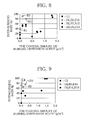
- FIGS. 8 and 9 show differences of Comparative Examples C1 and C2 and Embodiments E1 to E15, using the coating amount of the burning depression agent as a parameter.
- the cigarettes of Embodiments E1 to E5 which include the highly conducting bands 10 in the wrapping papers 6, have higher extinguishing rates than the cigarettes of Comparative Examples C1 and C2, which do not include any highly conducting bands.
- the cigarettes of Embodiments E6 to E14 which include the highly conducting bands 10 and the burning depression bands 16, have higher extinguishing rates than the cigarettes of Embodiments E1 to E5.
- FIGS. 8 and 9 show the cigarettes of Comparative Examples C1 and C2 and those of Embodiments E4, E6, E9 and E11, which achieve extinguishing rates of 60 percent or more.
- the burning depression bands of the cigarettes of Comparative Examples C1 and C2 have the burning depression agent of a coating amount of 1.3 g/m 2 or more.
- the burning depression bands of the cigarettes of Embodiments E4, E6, E9 and E11 have the burning depression agent of a coating amount of 0.1 to 0.24 g/m 2 .
- the burning depression bands 16 contribute to the improvement of extinguishing rate in cooperation with the highly conducting bands 10, and then the coating amount of the burning depression agent, which is required for formation of the burning depression bands 16, is drastically reduced.
- the highly conducting bands 10 are obtained by calendering, and the coating amount of the burning depression agent forming the burning depression bands 16 is very small as described above. Accordingly, the highly conducting bands 10 and the burning depression bands 16 do not greatly reduce air permeability of the wrapping papers 6 as a whole. Consequently, when the low ignition propensity cigarette of the invention is smoked, the smoker does not feel uneasiness and can smoke comfortably.
- FIGS. 10 and 11 show extinction positions with marks ⁇ and ⁇ , respectively, which are obtained during the cigarette extinction test.
- the cigarette shown in FIG. 10 includes wrapping paper A having only the highly conducting bands 10, whereas the cigarette shown in FIG. 11 includes wrapping paper having the highly conducting bands 10 and the burning depression bands 16.
- FIGS. 12 and 13 show extinction positions with marks ⁇ and ⁇ , respectively, which are obtained by the extinction test as in FIGS. 10 and 11 .
- the cigarettes shown in FIGS. 12 and 13 differ from those shown in FIGS. 10 and 11 only in that they include wrapping paper B instead of wrapping paper A.
- FIG. 14 schematically shows a calendering/coating apparatus.
- This calendering/coating apparatus carries out a method of producing the wrapping paper 6 having the highly conducting bands 10 and the burning depression bands 16.
- the calendering/coating apparatus has a running path 18 of web W for forming the wrapping paper 6.
- the running path 18 extends from a roll of the web W to a take-up reel 22, and includes a large number of guide rollers 20 for guiding the web W.
- a pair of pinch rollers 23a and 23b is disposed in an upstream portion of the running path 18.
- a calendering machine 24 is arranged downstream of the pinch rollers 23.
- the calendering machine 24 has the calendering roller 12, which is rotatably supported.
- a press roller 14 is situated in the vicinity of the calendering roller 12. The press roller 14 is capable of moving toward and away from the calendering roller 12.
- the press roller 14 is rotatably supported by a lower end of an arm 26.
- the arm 26 upwardly extends from the press roller 14 and rockably supported in the center thereof.
- a press cylinder 28 is connected to an upper end of the arm 26. The press cylinder 28 rocks the press roller 14 through the arm 26 by expanding and contracting motions thereof. As a result, the press roller 14 moves toward and away from the calendering roller 12.
- the highly conducting bands 10 each having a band-like shape are formed at the above-mentioned intervals. As shown in FIG. 15 , the highly conducting bands 10 are formed by partially concaving an inner surface of the web W. The highly conducting bands 10 therefore have less thickness than the web W.
- a coating device 32 is located in the running path 18 in a downstream side of the calendering machine 24.
- the coating device 32 includes a solution tank 34. Contained in the solution tank 34 is a solution of sodium alginate, namely, burning depression agent.
- the coating device 32 further includes a transfer roller 36, which is rotatably carried on the solution tank in a state partially immersed in the solution within the solution tank 34.
- the web W passes the transfer roller 36 while contacting an outer circumferential surface of the transfer roller 36 in a downstream side of the calendering machine 24.
- the solution of the burning depression agent is transferred, or coated, from the outer circumferential surface of the transfer roller 36 onto the highly conducting bands 10 of the web W. Therefore, as shown in FIG. 15 , the burning depression bands 16 are formed on the highly conducting bands 10.
- the burning depression bands 16 are superimposed upon the highly conducting bands 10.
- the transfer roller 36 is provided on the outer circumferential surface thereof with a transfer pattern for transferring the solution to the web W at intervals corresponding to the intervals of the highly conducting bands 10. and is rotated at circumferential velocity synchronized with the rotation of the calendering roller 12.
- the burning depression agent is coated onto the highly conducting bands 10 obtained by calendering, and therefore fits well onto the highly conducting bands 10. Accordingly, the burning depression bands 16 having desired coating amount can be formed only by once coating the highly conducting bands 10 with the burning depression agent.
- a drier 38 is arranged in the running path 18 in a downstream side of the coating device 32.
- the web W on which the burning depression bands 16 are formed passes the drier 38 in the downstream side of the coating device 32.
- the burning depression bands 16 of the web W are subjected to a drying process.
- the web W that has passed the drier 38 is reeled in the take-up reel 22.
- a roll R of the wrapping paper 6 having the highly conducting bands 10 and the burning depression bands 16 is formed in the take-up reel 22.
- a retrieve guide 40 is interposed between the calendering machine 24 and the coating device 32.
- the retrieve guide 40 is attached to a rod end of a retrieve cylinder 42.
- the retrieve cylinder 42 When the calendering/coating apparatus is at rest, the retrieve cylinder 42 extends from a state illustrated, to thereby upwardly move the retrieve guide 40.
- the upward movement of the retrieve guide 40 lifts a portion of the web W as shown by a chain double-dashed line, and then detaches the web W from the transfer roller 36 of the coating device 32.
- the roll R is supplied to a cigarette making machine, not shown, and is used for production of cigarettes.
- the calendering machine 24 may be disposed downstream of the coating device 32.
- the coating device 32 is preferably located downstream of the calendering machine 24.
- the calendering/coating apparatus itself is incorporable into a cigarette making machine.
- the invention is not limited to the low ignition propensity cigarette, the wrapping paper, and the method of producing wrapping paper according to the one embodiment. Instead, the invention may be modified in various ways.
- the highly conducting bands 10 are not limited to an example shown in FIG. 1 in terms of numbers, width, intervals or the like with respect to each cigarette.
- the burning depression bands 16 do not need to be completely superposed upon the highly conducting bands 10. That is, the burning depression bands 16 partially overlap with the highly conducting bands 10 in an axial direction of the cigarette 2, but may have portions superposed upon the entire highly conducting bands 10 in a circumferential direction of the cigarette 2.
- the web W namely, the wrapping paper 6, may have a highly conducting region 10a the entire region of which is subjected to calendering.
- the burning depression bands 16 may be formed at predetermined intervals in a longitudinal direction of the web W (cigarette) ( FIG. 16 ).
- there may be provided with an burning depression layer 16a instead of the burning depression band 16, which is formed in the entire region of a back surface of the web W (interior surface of the wrapping paper 6) ( FIG. 17 ).
- the burning depression bands 16 and layer 16a can be made of a burning depression agent other than sodium alginate.
Landscapes
- Paper (AREA)
- Cigarettes, Filters, And Manufacturing Of Filters (AREA)
Abstract
Description
- The present invention relates to a low ignition propensity cigarette that reduces the possibility of a burnable material when the lighted cigarette is placed on the burnable material, wrapping paper for the cigarette, and a method of producing wrapping paper.
- Well-known low ignition propensity cigarettes of this type include a self-distinguishing cigarette disclosed, for example, in
Patent Document 1. This cigarette has filling material and single wrapping paper that wraps the filling material in a rod-like shape. The wrapping paper includes high and low air permeable regions that are alternately arranged in an axial direction of the cigarette. The high and low air permeable regions each form a shape of a band extending in a circumferential direction of the cigarette. - When the self-extinguishing cigarette is in a smoldering state at its distal end as the smoker does not puff the cigarette after lighting it, the fire cone is automatically extinguished by the low air permeable region at the point of reaching the low air permeable region. Patent Document 1: Unexamined Japanese Patent Publication No.
1-225473 - The low air permeable region of the wrapping paper, which realizes the automatic extinguishment, has extremely low air permeability as compared to air permeability of a high air permeable region. There is a great difference in air permeability between the low and high air permeable regions. During smoking, therefore, a great difference occurs between the draw resistance of a cigarette when the fire cone is in the high air permeable region and the draw resistance of the cigarette when the fire cone is in the low air permeable region. This difference brings discomfort to the smoker.
- If the number of the low air permeable regions per self-extinguishing cigarette is increased in order to prevent an accident fire attributable to a cigarette, the suction resistance of the whole cigarette is inevitably increased. Such a cigarette fails to provide pleasant smoking to the smoker.
- It is an object of the invention to provide a low ignition propensity cigarette that is proper for prevention of an accident fire without ruining pleasant smoking, wrapping paper thereof, and a method of producing wrapping paper.
- In order to achieve the above object, the low ignition propensity cigarette according to the present invention comprises filling material and a single wrapping paper wrapping the filling material into a rod-like shape. The wrapping paper includes a highly conducting zone formed by calendering and having higher thermal conductivity than inherent thermal conductivity, and a burning depression layer formed by coating a burning depression agent onto the wrapping paper, for reducing burning speed of the wrapping paper.
- In a dangerous situation where the low ignition propensity cigarette is lighted and placed on a burnable material while having smolder, when the fire cone of the cigarette reaches the highly conducting zone, the highly conducting zone releases the heat of the fire cone to the burnable material to reduce the temperature of the fire cone. When the fire cone reaches the burning depression layer of the wrapping paper, the burning depression layer prevents the wrapping paper from being burnt and reduces the temperature of the fire cone. The temperature of the fire cone is thus reduced at any rate. Even in the dangerous situation as mentioned above, the possibility that the flame spreads to the burnable material is reduced.
- Preferably, the burning depression layer has a portion overlapping with the highly conducting zone. In this case, when the fire cone reaches overlapping portions of the burning depression layer and the highly conducting zone, the burning depression layer and the highly conducting zone reduce the temperature of the fire cone in cooperation with each other. This provides a higher effect of preventing the flame spreading.
- In a normal smoking state where a puff action is repeated with respect to the low ignition propensity cigarette, the fire cone can be supplied with oxygen from air that enters the cigarette. Regardless of the highly conducting zone and the burning depression layer, the fire cone is kept smoldering.
- When the burning depression layer is formed by coating the highly conducting zone with a burning depression agent after the highly conducting zone is formed in the wrapping paper by calendering, the burning depression agent fits well onto the highly conducting zone. It is therefore possible to form the burning depression layer simply by coating the highly conducting zone with the burning depression agent only once.
- To be specific, the highly conducting zone is either formed over the entire wrapping paper or as bands arranged at predetermined intervals in an axial direction of the low ignition propensity cigarette, the bands surrounding the entire circumference of the low ignition propensity cigarette. In this case, even if the low ignition propensity cigarette is placed on a burnable material in any condition, the bands of the highly conducting zone contact the burnable material and reduce the temperature of the fire cone of the cigarette.
- When the highly conducting zone is formed of a plurality of bands, it is preferable that the burning depression layer also include a plurality of bands, and that the bands of the highly conducting zone and of the burning depression layer be superposed upon each other. In this case, even in the dangerous situation as mentioned above, the bands of the highly conducting zone and of the burning depression layer reliably extinguish the fire cone of the cigarette and determine an extinction position of the fire cone.
- Preferably, the burning depression layer is formed on an inner surface of the wrapping paper (claim 6). In this case, since the highly conducting zone is located between the burning depression layer and the burnable material, functions of the highly conducting zone are not hampered by the burning depression layer in a dangerous situation.
- Preferably, the bands of the highly conducting zone are formed of recesses obtained by concaving parts of the wrapping paper by calendering, and the recesses each have slant edges on both ends separated away from each other in a longitudinal direction of the low ignition propensity cigarette.
- The present invention further provides wrapping paper for the above-described low ignition propensity cigarette. The wrapping paper includes the highly conducting zone and the burning depression layer.
- The invention further provides a method of producing the wrapping paper. The producing method includes the steps of forming in a web made of paper material the highly conducting zone having higher thermal conductivity than the inherent thermal conductivity of the web, and coating the web with the burning depression agent either before or after the calendering to form the burning depression layer for reducing burning speed of the web.
- Preferably, the calendering forms the highly conducting zone by applying pressure of 15 to 25 N/mm to the web.
- The low ignition propensity cigarette and the wrapping paper of the invention greatly reduce the possibility that flame spreads to a burnable material due to the fire cone of the low ignition propensity cigarette even in the dangerous situation.
- The air permeability of the highly conducting region obtained by calendering is not greatly reduced lower than the inherent air permeability of the wrapping paper. Moreover, when the highly conducting zone is formed of a plurality of bands, the draw resistance of the low ignition propensity is not substantially changed during smoking, so that the smoker does not feel discomfort.
- The method of producing the wrapping paper forms the highly conducting zone while regulating the pressure to be applied to the web within the range of from 15 to 25 N/mm. The method accordingly prevents the web from being ripped, and is capable of stably forming the highly conducting zone.
-
-
FIG. 1 is a schematic perspective view showing a low ignition propensity cigarette of one embodiment; -
FIG. 2 is a view showing a principle of calendering; -
FIG. 3 is a sectional view showing a part of an outer circumference of a calender roll shown inFIG. 2 ; -
FIG. 4 is a sectional view showing a calendered area formed in wrapping paper of the cigarette shown inFIG. 1 ; -
FIG. 5 is a longitudinal sectional view showing a part of the cigarette shown inFIG. 1 ; -
FIG. 6 is a graph showing extinguishing rates of test cigarettes; -
FIG. 7 is a graph showing extinguishing rates of test cigarettes; -
FIG. 8 is a graph showing relationship between a coating amount of a burning depression agent and the extinguishing rate; -
FIG. 9 is a graph showing relationship between a coating amount of the burning depression agent and the extinguishing rate; -
FIG. 10 is a view showing a result of an extinguishment test with respect to a cigarette including wrapping paper having only highly conducting zones; -
FIG. 11 is a view showing a result of an extinguishment test with respect to a cigarette including wrapping paper having highly conducting bands and burning depression bands; -
FIG. 12 is a view showing a result of an extinguishment test with respect to a cigarette identical to the cigarette shown inFIG. 10 except for air permeability of the wrapping paper; -
FIG. 13 is a view showing a result of an extinguishment test with respect to a cigarette identical to the cigarette shown inFIG. 11 except for air permeability of the wrapping paper; -
FIG. 14 is a schematic configuration view showing a calendering/coating apparatus; -
FIG. 15 is a view showing a web processed by the apparatus shown inFIG. 14 ; -
FIG. 16 is a view showing a web subjected to the calendering and the coating processing into an another form than the web shown inFIG. 15 ; and -
FIG. 17 is a view showing a web processed into a still another form. - A filter cigarette shown in
FIG. 1 includes acigarette 2 with a low ignition propensity, afilter 4 adjacent to a proximal end of thecigarette 2, and tippingpaper 7 connecting thecigarette 2 and thefilter 4 to each other. - The
cigarette 2 has fillingmaterial 8 andsingle wrapping paper 6 that wraps the filling material in a rod-like shape. The fillingmaterial 8 includes not only shred tobacco obtained by shredding leaf tobacco but also reconstructed shred tobacco obtained by shredding a reconstructed tobacco sheet, expanded shred tobacco obtained by subjecting shred tobacco to expansion processing, etc. - As for thermal conductivity, the
wrapping paper 6 has two highly conductingbands 10 functioning as a highly conducting zone. The highly conductingbands 10 are arranged away from each other in an axial direction of thecigarette 2 and extend around thecigarette 2 over the entire circumference of thecigarette 2. More specifically, a first highly conductingband 10 is set at 20 mm away from a distal end of thecigarette 2, and a second highly conductingband 10 at 20 mm away from the first highly conductingband 10 in the axial direction of thecigarette 2. The highly conductingbands 10 have a width of 7 mm. The second highly conductingband 10 and thetipping paper 7 are set at 5 mm away from each other. Thecigarette 2 has a total length of about 85 mm and a circumferential length of 25 mm. - The highly conducting
bands 10 are obtained by treating thewrapping paper 6 with calendering. The highly conductingbands 10 thus obtained have higher thermal conductivity than inherent thermal conductivity of other portions of thewrapping paper 6, which have not undergone the calendering, namely, the inherent thermal conductivity of the wrapping paper itself. -
FIG. 2 shows a calendering machine. The machine applies calendering to thewrapping paper 6 before thewrapping paper 6 is used for production of thecigarette 2. The machine includes acalendering roller 12 and apress roller 14. Thepress roller 14 is pressed against the calenderingroller 12 by a predetermined pressure, or more specifically, the pressure F ranging from 15 to 25 N/mm. When thewrapping paper 6 passes through between the calenderingroller 12 and thepress roller 14, the highly conductingbands 10 each having the above-mentioned width are formed in thewrapping paper 6 at predetermined intervals in a running direction of thewrapping paper 6. When thewrapping paper 6 subjected to the calendering is used for production of thecigarette 2, therefore, thecigarette 2 having two highly conductingbands 10 in thewrapping paper 6 is obtained as illustrated inFIG. 1 . - To be more specific, the calendering
roller 12 is made of steel. Pressingprotrusions 12 as shown inFIG. 3 are formed in an outer circumferential surface of thecalendering roller 12 at the above-mentioned intervals. As viewed in a cross-section of thecalendering roller 12, thepressing protrusion 12a has a trapezoidal shape. As viewed in a rotating direction of thecalendering roller 12, therefore, front and rear edge faces of thepressing protrusions 12a are both inclined. - After the
wrapping paper 6 passes through between the calenderingroller 12 and thepress roller 14, recessed portions shown inFIG. 4 are formed at intervals in an interior surface of thewrapping paper 6. These recessed portions become the highly conductingbands 10. The highly conductingbands 10 each have a shape in a complementary relationship with a shape of thepressing protrusion 12a, so that both end edge faces of each of the highly conductingbands 10, which are positioned away from each other in the longitudinal direction of thewrapping paper 6, are inclined, too. When the highly conductingbands 10 are formed of the recessed portions having the inclined edges, the load applied to thewrapping paper 6 during the calendering of thewrapping paper 6 is reduced, and thewrapping paper 6 is not ripped in the end edges of the highly conductingbands 10. - The
press roller 14 is made of steel, cotton fiber, aramid fiber, rubber or the like, and is not limited in material. Nevertheless, the material of thepress roller 14 is preferably softer than that of thecalendering roller 12. - In comparison between inherent thermal conductivity of the
wrapping paper 6 and thermal conductivity of the highly conductingbands 10, an increase rate of the thermal conductivity of the highly conducting bands to the inherent thermal conductivity depends upon the material of the calendering andpress rollers TABLE 1] Wrapping Paper Calendering Details of Calendering Average Thermal Conductivity (W/(K·m)) Increase Rate of Thermal Conductivity (%) A NO - 0.2435 - B NO - 0.2533 - A YES S & S (15) 0.2874 18.0 A YES S & S (18) 0.2616 7.4 A YES S & S (25) 0.2935 15.8 A YES C & S (25) 0.2837 16.5 A YES A & S (25) 0.2877 18.2 B YES S & S (15) 0.3146 24.2 B YES S & S (18) 0.3047 20.3 B YES S & S (25) 0.3235 27.7 B YES C & S (25) 0.3192 24.0 B YES A & S (25) 0.2893 14.2 - In TABLE 1, A and B represent wrapping papers different in air permeability. The wrapping papers A and B have 72 and 35 Coresta units, respectively. The average thermal conductivities of the wrapping papers A and B that have not been calendered indicate the inherent thermal conductivities of the wrapping papers A and B.
- The S & S (number), C & S (number), and A & S (number) presented under the Details of Calendering in TABLE 1 denote "the material of the
press roller 14" & "the material of the calendering roller" (pressure (N/mm)). Letters S, C, and A represent steel, cotton fiber, and aramid fiber, respectively. - As illustrated in
FIG. 5 , the highly conductingbands 10 are formed in the interior surface of thewrapping paper 6. In the recessed portions where the highly conductingbands 10 are formed, there are formed burning depression layers, or burningdepression bands 16. More specifically, the burningdepression bands 16 are formed by coating a solution of a burning depression agent, such as CMC (carboxymethyl cellulose) and sodium alginate, onto the highly conductingbands 10, namely, the recessed portions. The burningdepression bands 16 are superposed upon the respective highly conductingbands 10. - The burning
depression bands 16 compensate shortage of the thermal conductivity required for the highly conductingbands 10. More specifically, in such a dangerous situation that the lightedcigarette 2 is placed on a burnable material, the highly conductingbands 10 are required to have a thermal conductivity of at least about 0.45 W/(K·m) to reliably extinguish a smolder of thecigarette 2 in a state of smoldering in the highly conductingbands 10. - However, the thermal conductivities of the highly conducting
bands 10 in TABLE 1 are lower than 0.45 W/(K·m). The burningdepression bands 16 are superposed upon the highly conductingbands 10 and are made by a predetermined coating amount to compensate the shortage of the thermal conductivities of the highly conductingbands 10. - A low ignition propensity cigarette disclosed in Patent No. 3785144 includes inner wrapping paper having a thermal conductivity raging from 0.50 to 0.56 W/(K·m). Difference between the thermal conductivity of the inner wrapping paper and the thermal conductivity required for the highly conducting
bands 10 of the invention (0.45 W/(K· m)) results from the difference between thesingle wrapping paper 6 of the invention and the double wrapper disclosed in the above publication. The double wrapper has a double structure made of the inner wrapping paper and an outer wrapping paper. - TABLE 2 below shows results of evaluation on fire-extinguishing performance or low ignition propensity, of cigarettes C1, C2 and E1 to E15 in the above-described dangerous situation.
- C1 and C2 are cigarettes of Comparative Examples, which are made of wrapping papers A and B. E1 to E15 are cigarettes of Embodiments, which are made of wrapping papers having highly conducting
bands 10 obtained by calendering of various forms and wrapping papers having not only the highly conductingbands 10 but also burningdepression bands 16. In TABLE 2, α represents the presence of the burningdepression bands 16 made by a coating amount of 0.10 g/m2, and β represents the presence of the burningdepression bands 16 made by a coating amount of 0.24 g/m2.[TABLE 2] Wrapping paper conditions Shred filling amount (g/cig) The number of cigarettes burnt to full lengths The number of cigarettes extinguished before being burnt to full lengths The number of tested cigarettes Extinguishing rate (%) C1 A 0.6400 20 0 20 0 C2 B 20 0 20 0 E1 A (S&S(15)) 12 8 20 40 E2 A(C&S(15)) 15 5 20 25 E3 A(A&S(15)) 17 3 20 15 E4 B(S&S(15)) 6 14 20 70 E5 B(C&S(15)) 12 8 20 40 E6 A(S&S(15))+α 2 18 20 90 E7 A(G&S(15))+α 9 11 20 55 E8 A(A&S(15))+α 10 10 20 50 E9 B(S&S(15))+α 7 13 20 65 E10 B(C&S(15))+α 10 10 20 50 E11 A(S&S(15))+β 4 16 20 80 E12 A(C&S(15))+β 10 10 20 50 E13 A(A&S(15))+β 9 11 20 55 E14 B(S&S(15))+β 5 15 20 75 E15 B(C&S(15))+β 14 6 20 30 - The results of evaluation shown in TABLE 2 were obtained by a Cigarette Extinction Test Method. In this test method, a cigarette to be tested is first placed upright. In this position, the cigarette lets to be burnt up to 15 mm away from a top end thereof. Then, the lighted cigarette is left to lie in a horizontal position on a burnable material that is formed by superposing ten sheets of filter paper (item: Whatman No.2). The extinguishing rates shown in TABLE 2 indicate the percentage of the number of cigarettes the smolders of which were extinguished before the cigarettes were burnt to their full lengths with respect to the number of the lighted cigarettes that were burnt to their full lengths.
- The results of evaluation in TABLE 2 are shown in graphs of
FIGS. 6 to 9 as well. -
FIG. 6 shows the extinguishing rates of Comparative Example C1 and Embodiments E1 to E3.FIG. 7 shows the extinguishing rates of Comparative Example C2 and Embodiments E4 and E5.FIGS. 8 and 9 show differences of Comparative Examples C1 and C2 and Embodiments E1 to E15, using the coating amount of the burning depression agent as a parameter. - As is apparent from
FIGS. 6 and 7 , the cigarettes of Embodiments E1 to E5, which include the highly conductingbands 10 in thewrapping papers 6, have higher extinguishing rates than the cigarettes of Comparative Examples C1 and C2, which do not include any highly conducting bands. - As is evident from
FIGS. 8 and 9 , the cigarettes of Embodiments E6 to E14, which include the highly conductingbands 10 and the burningdepression bands 16, have higher extinguishing rates than the cigarettes of Embodiments E1 to E5. -
FIGS. 8 and 9 show the cigarettes of Comparative Examples C1 and C2 and those of Embodiments E4, E6, E9 and E11, which achieve extinguishing rates of 60 percent or more. The burning depression bands of the cigarettes of Comparative Examples C1 and C2 have the burning depression agent of a coating amount of 1.3 g/m2 or more. The burning depression bands of the cigarettes of Embodiments E4, E6, E9 and E11 have the burning depression agent of a coating amount of 0.1 to 0.24 g/m2. This means that, in the case of Embodiments E4, E6, E9 and E11, the burningdepression bands 16 contribute to the improvement of extinguishing rate in cooperation with the highly conductingbands 10, and then the coating amount of the burning depression agent, which is required for formation of the burningdepression bands 16, is drastically reduced. - The highly conducting
bands 10 are obtained by calendering, and the coating amount of the burning depression agent forming the burningdepression bands 16 is very small as described above. Accordingly, the highly conductingbands 10 and the burningdepression bands 16 do not greatly reduce air permeability of thewrapping papers 6 as a whole. Consequently, when the low ignition propensity cigarette of the invention is smoked, the smoker does not feel uneasiness and can smoke comfortably. -
FIGS. 10 and 11 show extinction positions with marks Δ and ○, respectively, which are obtained during the cigarette extinction test. The cigarette shown inFIG. 10 includes wrapping paper A having only the highly conductingbands 10, whereas the cigarette shown inFIG. 11 includes wrapping paper having the highly conductingbands 10 and the burningdepression bands 16. -
FIGS. 12 and 13 show extinction positions with marks Δ and ○, respectively, which are obtained by the extinction test as inFIGS. 10 and 11 . The cigarettes shown inFIGS. 12 and 13 differ from those shown inFIGS. 10 and 11 only in that they include wrapping paper B instead of wrapping paper A. - As is clear from
FIGS. 10 to 13 , in the case of cigarettes having both the highly conductingbands 10 and the burningdepression bands 16, the extinction positions are concentrated on where the highly conductingbands 10 and the burningdepression bands 16 are disposed. This means that the highly conductingbands 10 and the burningdepression bands 16 effectively extinguish smolder in cooperation with each other. -
FIG. 14 schematically shows a calendering/coating apparatus. This calendering/coating apparatus carries out a method of producing thewrapping paper 6 having the highly conductingbands 10 and the burningdepression bands 16. - The calendering/coating apparatus has a running path 18 of web W for forming the
wrapping paper 6. The running path 18 extends from a roll of the web W to a take-up reel 22, and includes a large number ofguide rollers 20 for guiding the web W. - A pair of
pinch rollers machine 24 is arranged downstream of the pinch rollers 23. The calenderingmachine 24 has thecalendering roller 12, which is rotatably supported. Apress roller 14 is situated in the vicinity of thecalendering roller 12. Thepress roller 14 is capable of moving toward and away from the calenderingroller 12. - To be more specific, the
press roller 14 is rotatably supported by a lower end of anarm 26. Thearm 26 upwardly extends from thepress roller 14 and rockably supported in the center thereof. Apress cylinder 28 is connected to an upper end of thearm 26. Thepress cylinder 28 rocks thepress roller 14 through thearm 26 by expanding and contracting motions thereof. As a result, thepress roller 14 moves toward and away from the calenderingroller 12. - While the calendering
roller 12 is rotated, the web W passes through between the calenderingroller 12 and thepress roller 14. In this process, the web W is intermittently subjected to the calendering. Consequently, in the web W, the highly conductingbands 10 each having a band-like shape are formed at the above-mentioned intervals. As shown inFIG. 15 , the highly conductingbands 10 are formed by partially concaving an inner surface of the web W. The highly conductingbands 10 therefore have less thickness than the web W. - A
coating device 32 is located in the running path 18 in a downstream side of the calenderingmachine 24. Thecoating device 32 includes asolution tank 34. Contained in thesolution tank 34 is a solution of sodium alginate, namely, burning depression agent. Thecoating device 32 further includes atransfer roller 36, which is rotatably carried on the solution tank in a state partially immersed in the solution within thesolution tank 34. - As is obvious from
FIG. 14 , the web W passes thetransfer roller 36 while contacting an outer circumferential surface of thetransfer roller 36 in a downstream side of the calenderingmachine 24. In this process, the solution of the burning depression agent is transferred, or coated, from the outer circumferential surface of thetransfer roller 36 onto the highly conductingbands 10 of the web W. Therefore, as shown inFIG. 15 , the burningdepression bands 16 are formed on the highly conductingbands 10. The burningdepression bands 16 are superimposed upon the highly conductingbands 10. To be more concrete, thetransfer roller 36 is provided on the outer circumferential surface thereof with a transfer pattern for transferring the solution to the web W at intervals corresponding to the intervals of the highly conductingbands 10. and is rotated at circumferential velocity synchronized with the rotation of thecalendering roller 12. - The burning depression agent is coated onto the highly conducting
bands 10 obtained by calendering, and therefore fits well onto the highly conductingbands 10. Accordingly, the burningdepression bands 16 having desired coating amount can be formed only by once coating the highly conductingbands 10 with the burning depression agent. - A drier 38 is arranged in the running path 18 in a downstream side of the
coating device 32. The web W on which the burningdepression bands 16 are formed passes the drier 38 in the downstream side of thecoating device 32. In this process, the burningdepression bands 16 of the web W are subjected to a drying process. The web W that has passed the drier 38 is reeled in the take-up reel 22. A roll R of thewrapping paper 6 having the highly conductingbands 10 and the burningdepression bands 16 is formed in the take-up reel 22. - In the running path 18, a retrieve
guide 40 is interposed between the calenderingmachine 24 and thecoating device 32. The retrieveguide 40 is attached to a rod end of a retrievecylinder 42. - When the calendering/coating apparatus is at rest, the retrieve
cylinder 42 extends from a state illustrated, to thereby upwardly move the retrieveguide 40. The upward movement of the retrieveguide 40 lifts a portion of the web W as shown by a chain double-dashed line, and then detaches the web W from thetransfer roller 36 of thecoating device 32. - The roll R is supplied to a cigarette making machine, not shown, and is used for production of cigarettes.
- In the calendering/coating apparatus, the calendering
machine 24 may be disposed downstream of thecoating device 32. However, considering the coating properties of the burning depression agent, thecoating device 32 is preferably located downstream of the calenderingmachine 24. The calendering/coating apparatus itself is incorporable into a cigarette making machine. - The invention is not limited to the low ignition propensity cigarette, the wrapping paper, and the method of producing wrapping paper according to the one embodiment. Instead, the invention may be modified in various ways.
- For instance, the highly conducting
bands 10 are not limited to an example shown inFIG. 1 in terms of numbers, width, intervals or the like with respect to each cigarette. The burningdepression bands 16 do not need to be completely superposed upon the highly conductingbands 10. That is, the burningdepression bands 16 partially overlap with the highly conductingbands 10 in an axial direction of thecigarette 2, but may have portions superposed upon the entire highly conductingbands 10 in a circumferential direction of thecigarette 2. Furthermore, as illustrated inFIG. 16 , the web W, namely, thewrapping paper 6, may have a highly conductingregion 10a the entire region of which is subjected to calendering. In this case, the burningdepression bands 16 may be formed at predetermined intervals in a longitudinal direction of the web W (cigarette) (FIG. 16 ). Alternatively, there may be provided with an burningdepression layer 16a, instead of the burningdepression band 16, which is formed in the entire region of a back surface of the web W (interior surface of the wrapping paper 6) (FIG. 17 ). - The burning
depression bands 16 andlayer 16a can be made of a burning depression agent other than sodium alginate.
Claims (16)
- A low ignition propensity cigarette comprising:filling material; anda single wrapping paper wrapping said filling material into a rod-like shape, whereinsaid wrapping paper includes:a highly conducting zone formed by calendering said wrapping paper and having higher thermal conductivity than inherent thermal conductivity of said wrapping paper, anda burning depression layer formed by coating a burning depression agent onto said wrapping paper, for reducing burning speed of said wrapping paper.
- The low ignition propensity cigarette according to claim 1, wherein said burning depression layer has a portion overlapping with said highly conducting zone.
- The low ignition propensity cigarette according to claim 1, wherein said highly conducting zone is formed over the entire wrapping paper.
- The low ignition propensity cigarette according to claim 2, wherein said highly conducting zone includes bands arranged at predetermined intervals in an axial direction of the low ignition propensity cigarette, the band surrounding the entire circumference of the low ignition propensity cigarette.
- The low ignition propensity cigarette according to claim 4, wherein said burning depression layer includes a plurality of bands as in said highly conducting zone, and the bands of said highly conducting zone and of said burning depression layer are superposed upon each other.
- The low ignition propensity cigarette according to claim 5, wherein said burning depression layer is formed on an inner surface of said wrapping paper.
- The low ignition propensity cigarette according to claim 4, wherein the bands of said highly conducting zone are formed of recesses obtained by concaving parts of the wrapping paper by calendering, and the recesses each have slant edges on both ends separated away from each other in a longitudinal direction of the low ignition propensity cigarette.
- Wrapping paper for a low ignition propensity cigarette comprising:paper material;a highly conducting zone formed by calendering said paper material and having higher thermal conductivity than inherent thermal conductivity of said paper material, anda burning depression layer formed by coating said paper material with a burning depression agent, for reducing burning speed of said paper material.
- The wrapping paper according to claim 8, wherein said burning depression layer has a portion overlapping with said highly conducting zone.
- The wrapping paper according to claim 9, wherein said highly conducting zone is formed over the entire paper material.
- The wrapping paper according to claim 8, wherein said highly conducting zone includes bands arranged at predetermined intervals in a longitudinal direction of said paper material, and the bands extending across the entire width of said paper material.
- The wrapping paper according to claim 11, wherein said burning depression layer includes a plurality of bands as in said highly conducting zone, and the bands of said highly conducting zone and of said burning depression layer are superposed upon each other.
- The wrapping paper according to claim 12, wherein said burning depression layer is formed on an inner surface of said paper material.
- The wrapping material according to claim 8, wherein the bands of said highly conducting zone are formed of recesses obtained by concaving parts of said wrapping paper by calendering, and the recesses each have slant edges on both ends separated away from each other in a longitudinal direction of said paper material.
- A method of producing wrapping paper for a low ignition propensity cigarette, comprising steps of:forming a highly conducting zone in web made of paper material by calendering, said highly conducting zone having higher thermal conductivity than inherent thermal conductivity of the paper material, andcoating the web with a burning depression agent either before or after the calendering to form a burning depression layer for reducing burning speed of the web.
- The method of producing wrapping paper for a low ignition propensity cigarette according to claim 14, wherein the calendering forms said highly conducting zone by applying pressure of 15 to 25 N/mm to the web.
Applications Claiming Priority (2)
| Application Number | Priority Date | Filing Date | Title |
|---|---|---|---|
| JP2006333317 | 2006-12-11 | ||
| PCT/JP2007/073502 WO2008072523A1 (en) | 2006-12-11 | 2007-12-05 | Low fire spreading cigarette, wrapping paper for the cigarette, and method of producing wrapping paper |
Publications (3)
| Publication Number | Publication Date |
|---|---|
| EP2100524A1 true EP2100524A1 (en) | 2009-09-16 |
| EP2100524A4 EP2100524A4 (en) | 2012-06-27 |
| EP2100524B1 EP2100524B1 (en) | 2014-10-29 |
Family
ID=39511544
Family Applications (1)
| Application Number | Title | Priority Date | Filing Date |
|---|---|---|---|
| EP07850126.9A Active EP2100524B1 (en) | 2006-12-11 | 2007-12-05 | Low fire spreading cigarette, wrapping paper for the cigarette, and method of producing wrapping paper |
Country Status (12)
| Country | Link |
|---|---|
| US (1) | US9739013B2 (en) |
| EP (1) | EP2100524B1 (en) |
| JP (1) | JP4859146B2 (en) |
| KR (1) | KR101082646B1 (en) |
| CN (1) | CN101605471B (en) |
| CA (1) | CA2671475C (en) |
| ES (1) | ES2522902T3 (en) |
| MY (1) | MY148269A (en) |
| RU (1) | RU2412623C1 (en) |
| TW (1) | TWI329003B (en) |
| UA (1) | UA92852C2 (en) |
| WO (1) | WO2008072523A1 (en) |
Cited By (3)
| Publication number | Priority date | Publication date | Assignee | Title |
|---|---|---|---|---|
| US8568896B2 (en) | 2009-11-25 | 2013-10-29 | Japan Tobacco Inc. | Low ignition propensity wrapping paper and method and machine of manufacturing same |
| EP2725138B1 (en) | 2011-12-02 | 2016-10-12 | Mudanjiang Hengfeng Paper Co., Ltd | Gravure press for manufacturing fire-retardant banded cigarette paper and manufacturing method for same |
| CN108142976A (en) * | 2017-11-29 | 2018-06-12 | 昆明理工大学 | A kind of cut tobacco Drying Technology Parameter optimization method |
Families Citing this family (24)
| Publication number | Priority date | Publication date | Assignee | Title |
|---|---|---|---|---|
| RU2503383C2 (en) * | 2008-02-22 | 2014-01-10 | Швайцер-Маудит Интернешнл, Инк. | Treated wrapping sections to reduce smoking products ignition capacity characteristics |
| WO2011104866A1 (en) * | 2010-02-26 | 2011-09-01 | 日本たばこ産業株式会社 | Production method and production device for coated paper |
| DE102010026178A1 (en) | 2010-07-06 | 2012-01-12 | Tews Elektronik Gmbh & Co. Kg | Apparatus for the production of cigarettes in the tobacco processing industry and a method for this purpose |
| DE102010039088A1 (en) * | 2010-08-09 | 2012-02-09 | Hauni Maschinenbau Ag | Wrapping paper strip, useful for tobacco processing industry, comprises longitudinally extended airtight paper strip having low ignition propensity-free zones with increased air permeability between airtight low ignition propensity-zones |
| GB201018310D0 (en) | 2010-10-29 | 2010-12-15 | British American Tobacco Co | Ventilated smoking article |
| CN102094364A (en) * | 2010-11-24 | 2011-06-15 | 云南烟草科学研究院 | Cigarette paper with low ignition tendency and preparation method thereof |
| WO2013024519A1 (en) * | 2011-08-12 | 2013-02-21 | 日本たばこ産業株式会社 | Cigarette rolling paper manufacturing device and manufacturing method |
| CN102296484B (en) * | 2011-09-20 | 2013-07-10 | 云南烟草科学研究院 | Flame-retardant coating for low-ignition tendency cigarette paper |
| KR101382650B1 (en) | 2011-10-25 | 2014-04-08 | 주식회사 케이티앤지 | Coating composition of low ignition propensity cigarette paper and cigarette using the same |
| KR101235693B1 (en) * | 2011-11-08 | 2013-02-21 | 주식회사 케이티앤지 | Device of processing low ignition propensity cigarette paper and device of manufacturing low ignition propensity cigarette paper including the same |
| CN102493280A (en) * | 2011-12-02 | 2012-06-13 | 牡丹江恒丰纸业股份有限公司 | Device and method for manufacturing cigarette paper with flame-retardant belt |
| RU2517105C2 (en) * | 2012-06-13 | 2014-05-27 | Федеральное государственное бюджетное образовательное учреждение высшего профессионального образования "Челябинская государственная агроинженерная академия" | Cigarette extinguishment method and self-extinguishing cigarette |
| CA2887696C (en) | 2012-10-11 | 2021-07-06 | Schweitzer-Mauduit International, Inc. | Wrapper having reduced ignition proclivity characteristics |
| CN103622156B (en) * | 2013-11-14 | 2016-02-10 | 湖南中烟工业有限责任公司 | The application of polydextrose and sodium carboxymethylcellulose complex additive |
| GB201505515D0 (en) * | 2015-03-31 | 2015-05-13 | British American Tobacco Co | A composite web and method of manufacturing a smoking article component |
| CN104805730B (en) * | 2015-04-07 | 2017-04-26 | 牡丹江恒丰纸业股份有限公司 | Burning inhibition composition with carbon monoxide reduction function for cigarette paper and applying method and manufacturing method thereof |
| WO2016208065A1 (en) * | 2015-06-26 | 2016-12-29 | 日本たばこ産業株式会社 | Cigarette paper, manufacturing method and manufacturing device thereof, and cigarette |
| CN112368444B (en) | 2018-07-02 | 2022-11-01 | 日本烟草产业株式会社 | Cigarette paper for non-combustion heating type smoking article, non-combustion heating type smoking article and electric heating type smoking system |
| KR102372859B1 (en) | 2018-11-19 | 2022-03-08 | 주식회사 케이티앤지 | Apparatus for generating aerosol based on external heating and cigarette thereof |
| EP4048098A1 (en) * | 2019-10-23 | 2022-08-31 | JT International SA | Deeply embossed highly permeable cigarette paper |
| KR102536403B1 (en) | 2020-03-02 | 2023-05-24 | 주식회사 케이티앤지 | Apparatus for generating aerosol based on external heating and cigarette thereof |
| GB202115008D0 (en) * | 2021-10-20 | 2021-12-01 | Nicoventures Trading Ltd | Article with combustion retarding properties and uses thereof |
| CN115187049A (en) * | 2022-07-07 | 2022-10-14 | 云南中烟工业有限责任公司 | Comprehensive analysis method for evaluating importance of cigarette combustion quality indexes |
| KR20250100785A (en) | 2022-12-26 | 2025-07-03 | 니뽄 다바코 산교 가부시키가이샤 | Components and smoking articles that provide aroma by flavoring ingredients |
Family Cites Families (17)
| Publication number | Priority date | Publication date | Assignee | Title |
|---|---|---|---|---|
| GB1524211A (en) * | 1975-01-09 | 1978-09-06 | British American Tobacco Co | Smoking articles |
| US4615345A (en) * | 1983-08-08 | 1986-10-07 | Kimberly-Clark Corporation | Wrapper constructions for self-extinguishing smoking articles |
| US4924888A (en) * | 1987-05-15 | 1990-05-15 | R. J. Reynolds Tobacco Company | Smoking article |
| DE3802645A1 (en) | 1988-01-29 | 1989-08-10 | Reemtsma H F & Ph | QUICK OR SELF-EXTINGUISHING CIGARETTE |
| GB9005072D0 (en) * | 1990-03-07 | 1990-05-02 | Bentley David Ltd | Improvements relating to calender and embossing bowls |
| CN2081211U (en) * | 1990-12-24 | 1991-07-24 | 刘俊 | Safety cigarette |
| GB9524450D0 (en) * | 1995-11-30 | 1996-01-31 | Kaysersberg Sa | Sheet of absorbent paper which includes watermarked patterns,manufacturing process and manufacturing device |
| NZ524597A (en) * | 2000-09-18 | 2005-06-24 | Rothmans Benson & Hedges | Low sidestream smoke cigarette with non-combustible treatment material |
| SE519723C2 (en) * | 2001-01-04 | 2003-04-01 | Sandvik Ab | Heating device for splicing of light fibers |
| KR100532879B1 (en) * | 2001-01-15 | 2005-12-01 | 니뽄 다바코 산교 가부시키가이샤 | Cigarette |
| PT1417899E (en) * | 2001-08-13 | 2007-11-09 | Miquel Y Costas & Miquel Sa | Method of preparing paper for self-extinguishing cigarettes |
| US6929013B2 (en) * | 2001-08-14 | 2005-08-16 | R. J. Reynolds Tobacco Company | Wrapping materials for smoking articles |
| US6779530B2 (en) * | 2002-01-23 | 2004-08-24 | Schweitzer-Mauduit International, Inc. | Smoking articles with reduced ignition proclivity characteristics |
| RU2004133892A (en) * | 2002-04-22 | 2005-08-10 | Ротманс, Бенсон Энд Хеджиз, Инк. (Ca) | LOW-FLAMMABLE CIGARETT HAVING METAL OXIDE IN THE CIGARETTE WRAPPING AS OXYGEN DONOR |
| JP4257851B2 (en) * | 2004-03-24 | 2009-04-22 | 日本たばこ産業株式会社 | Low-spreading cigarette wrapping paper, filter cigarette using the wrapping paper, and method for producing the wrapping paper |
| UA90299C2 (en) * | 2005-03-15 | 2010-04-26 | Джапан Тобакко Инк. | Cigarette paper with low fire spreading |
| DE202008007008U1 (en) * | 2008-05-23 | 2008-08-14 | Mcairlaid's Vliesstoffe Gmbh & Co. Kg | Absorbent fibrous web |
-
2007
- 2007-05-12 UA UAA200907260A patent/UA92852C2/en unknown
- 2007-12-05 CA CA2671475A patent/CA2671475C/en not_active Expired - Fee Related
- 2007-12-05 JP JP2008549261A patent/JP4859146B2/en not_active Expired - Fee Related
- 2007-12-05 MY MYPI20092300A patent/MY148269A/en unknown
- 2007-12-05 RU RU2009126555/21A patent/RU2412623C1/en not_active IP Right Cessation
- 2007-12-05 WO PCT/JP2007/073502 patent/WO2008072523A1/en not_active Ceased
- 2007-12-05 EP EP07850126.9A patent/EP2100524B1/en active Active
- 2007-12-05 KR KR1020097011456A patent/KR101082646B1/en not_active Expired - Fee Related
- 2007-12-05 ES ES07850126.9T patent/ES2522902T3/en active Active
- 2007-12-05 CN CN2007800511166A patent/CN101605471B/en not_active Expired - Fee Related
- 2007-12-10 TW TW096146969A patent/TWI329003B/en not_active IP Right Cessation
-
2009
- 2009-06-10 US US12/481,908 patent/US9739013B2/en not_active Expired - Fee Related
Cited By (4)
| Publication number | Priority date | Publication date | Assignee | Title |
|---|---|---|---|---|
| US8568896B2 (en) | 2009-11-25 | 2013-10-29 | Japan Tobacco Inc. | Low ignition propensity wrapping paper and method and machine of manufacturing same |
| EP2725138B1 (en) | 2011-12-02 | 2016-10-12 | Mudanjiang Hengfeng Paper Co., Ltd | Gravure press for manufacturing fire-retardant banded cigarette paper and manufacturing method for same |
| CN108142976A (en) * | 2017-11-29 | 2018-06-12 | 昆明理工大学 | A kind of cut tobacco Drying Technology Parameter optimization method |
| CN108142976B (en) * | 2017-11-29 | 2020-05-15 | 昆明理工大学 | A kind of optimization method of leaf silk drying process parameters |
Also Published As
| Publication number | Publication date |
|---|---|
| UA92852C2 (en) | 2010-12-10 |
| JPWO2008072523A1 (en) | 2010-03-25 |
| CN101605471A (en) | 2009-12-16 |
| JP4859146B2 (en) | 2012-01-25 |
| US9739013B2 (en) | 2017-08-22 |
| RU2412623C1 (en) | 2011-02-27 |
| TWI329003B (en) | 2010-08-21 |
| KR101082646B1 (en) | 2011-11-14 |
| CA2671475A1 (en) | 2008-06-19 |
| EP2100524A4 (en) | 2012-06-27 |
| EP2100524B1 (en) | 2014-10-29 |
| WO2008072523A1 (en) | 2008-06-19 |
| CN101605471B (en) | 2011-05-11 |
| MY148269A (en) | 2013-03-29 |
| US20090301506A1 (en) | 2009-12-10 |
| CA2671475C (en) | 2011-09-20 |
| RU2009126555A (en) | 2011-01-20 |
| KR20090089356A (en) | 2009-08-21 |
| ES2522902T3 (en) | 2014-11-19 |
| HK1133994A1 (en) | 2010-04-16 |
| TW200901905A (en) | 2009-01-16 |
Similar Documents
| Publication | Publication Date | Title |
|---|---|---|
| EP2100524B1 (en) | Low fire spreading cigarette, wrapping paper for the cigarette, and method of producing wrapping paper | |
| EP2259692B1 (en) | Treated areas on a wrapper for reducing the ignition proclivity characteristics of a smoking article | |
| EP1352573B1 (en) | Low fire spreading cigarette | |
| JP4672261B2 (en) | Smoking products with reduced ignition tendency characteristics | |
| KR101564780B1 (en) | Slit band paper | |
| KR20160072091A (en) | Heated aerosol-generating articles comprising improved rods | |
| US20020185143A1 (en) | Reduced ignition propensity smoking article | |
| RU2566266C2 (en) | Smoking product wrapping with low igniting capacity, smoking product, method and device | |
| KR20050074635A (en) | Cigarette with burn rate modification | |
| JPH01225473A (en) | Cigarette rapidly or automatically extinguished | |
| EP3935965B1 (en) | Method for manufacturing a wrapper for a non-combustible cigarette | |
| AU2003207620A1 (en) | Smoking articles with reduced ignition proclivity characteristics | |
| KR100390356B1 (en) | Low sub-flow smoke type cigarette | |
| HK1133994B (en) | Low fire spreading cigarette, wrapping paper for the cigarette, and method of producing wrapping paper | |
| WO2025126480A1 (en) | Paper plug and flavor inhalation article |
Legal Events
| Date | Code | Title | Description |
|---|---|---|---|
| PUAI | Public reference made under article 153(3) epc to a published international application that has entered the european phase |
Free format text: ORIGINAL CODE: 0009012 |
|
| 17P | Request for examination filed |
Effective date: 20090610 |
|
| AK | Designated contracting states |
Kind code of ref document: A1 Designated state(s): AT BE BG CH CY CZ DE DK EE ES FI FR GB GR HU IE IS IT LI LT LU LV MC MT NL PL PT RO SE SI SK TR |
|
| AX | Request for extension of the european patent |
Extension state: AL BA HR MK RS |
|
| A4 | Supplementary search report drawn up and despatched |
Effective date: 20120531 |
|
| RIC1 | Information provided on ipc code assigned before grant |
Ipc: D21H 25/04 20060101ALI20120524BHEP Ipc: D21H 27/00 20060101ALI20120524BHEP Ipc: A24D 1/02 20060101AFI20120524BHEP |
|
| 17Q | First examination report despatched |
Effective date: 20130313 |
|
| GRAP | Despatch of communication of intention to grant a patent |
Free format text: ORIGINAL CODE: EPIDOSNIGR1 |
|
| INTG | Intention to grant announced |
Effective date: 20140808 |
|
| GRAS | Grant fee paid |
Free format text: ORIGINAL CODE: EPIDOSNIGR3 |
|
| GRAA | (expected) grant |
Free format text: ORIGINAL CODE: 0009210 |
|
| AK | Designated contracting states |
Kind code of ref document: B1 Designated state(s): AT BE BG CH CY CZ DE DK EE ES FI FR GB GR HU IE IS IT LI LT LU LV MC MT NL PL PT RO SE SI SK TR |
|
| AX | Request for extension of the european patent |
Extension state: AL BA HR MK RS |
|
| REG | Reference to a national code |
Ref country code: GB Ref legal event code: FG4D |
|
| REG | Reference to a national code |
Ref country code: CH Ref legal event code: NV Representative=s name: NOVAGRAAF INTERNATIONAL SA, CH Ref country code: CH Ref legal event code: EP |
|
| REG | Reference to a national code |
Ref country code: AT Ref legal event code: REF Ref document number: 693125 Country of ref document: AT Kind code of ref document: T Effective date: 20141115 |
|
| REG | Reference to a national code |
Ref country code: IE Ref legal event code: FG4D Ref country code: ES Ref legal event code: FG2A Ref document number: 2522902 Country of ref document: ES Kind code of ref document: T3 Effective date: 20141119 |
|
| REG | Reference to a national code |
Ref country code: RO Ref legal event code: EPE |
|
| REG | Reference to a national code |
Ref country code: DE Ref legal event code: R096 Ref document number: 602007039075 Country of ref document: DE Effective date: 20141211 |
|
| REG | Reference to a national code |
Ref country code: SE Ref legal event code: TRGR |
|
| REG | Reference to a national code |
Ref country code: NL Ref legal event code: T3 |
|
| REG | Reference to a national code |
Ref country code: GR Ref legal event code: EP Ref document number: 20140402371 Country of ref document: GR Effective date: 20141223 |
|
| REG | Reference to a national code |
Ref country code: LT Ref legal event code: MG4D |
|
| PG25 | Lapsed in a contracting state [announced via postgrant information from national office to epo] |
Ref country code: FI Free format text: LAPSE BECAUSE OF FAILURE TO SUBMIT A TRANSLATION OF THE DESCRIPTION OR TO PAY THE FEE WITHIN THE PRESCRIBED TIME-LIMIT Effective date: 20141029 Ref country code: PT Free format text: LAPSE BECAUSE OF FAILURE TO SUBMIT A TRANSLATION OF THE DESCRIPTION OR TO PAY THE FEE WITHIN THE PRESCRIBED TIME-LIMIT Effective date: 20150302 Ref country code: IS Free format text: LAPSE BECAUSE OF FAILURE TO SUBMIT A TRANSLATION OF THE DESCRIPTION OR TO PAY THE FEE WITHIN THE PRESCRIBED TIME-LIMIT Effective date: 20150228 Ref country code: LT Free format text: LAPSE BECAUSE OF FAILURE TO SUBMIT A TRANSLATION OF THE DESCRIPTION OR TO PAY THE FEE WITHIN THE PRESCRIBED TIME-LIMIT Effective date: 20141029 |
|
| PG25 | Lapsed in a contracting state [announced via postgrant information from national office to epo] |
Ref country code: CY Free format text: LAPSE BECAUSE OF FAILURE TO SUBMIT A TRANSLATION OF THE DESCRIPTION OR TO PAY THE FEE WITHIN THE PRESCRIBED TIME-LIMIT Effective date: 20141029 Ref country code: PL Free format text: LAPSE BECAUSE OF FAILURE TO SUBMIT A TRANSLATION OF THE DESCRIPTION OR TO PAY THE FEE WITHIN THE PRESCRIBED TIME-LIMIT Effective date: 20141029 Ref country code: LV Free format text: LAPSE BECAUSE OF FAILURE TO SUBMIT A TRANSLATION OF THE DESCRIPTION OR TO PAY THE FEE WITHIN THE PRESCRIBED TIME-LIMIT Effective date: 20141029 |
|
| REG | Reference to a national code |
Ref country code: DE Ref legal event code: R097 Ref document number: 602007039075 Country of ref document: DE |
|
| PG25 | Lapsed in a contracting state [announced via postgrant information from national office to epo] |
Ref country code: DK Free format text: LAPSE BECAUSE OF FAILURE TO SUBMIT A TRANSLATION OF THE DESCRIPTION OR TO PAY THE FEE WITHIN THE PRESCRIBED TIME-LIMIT Effective date: 20141029 Ref country code: CZ Free format text: LAPSE BECAUSE OF FAILURE TO SUBMIT A TRANSLATION OF THE DESCRIPTION OR TO PAY THE FEE WITHIN THE PRESCRIBED TIME-LIMIT Effective date: 20141029 Ref country code: SK Free format text: LAPSE BECAUSE OF FAILURE TO SUBMIT A TRANSLATION OF THE DESCRIPTION OR TO PAY THE FEE WITHIN THE PRESCRIBED TIME-LIMIT Effective date: 20141029 Ref country code: LU Free format text: LAPSE BECAUSE OF FAILURE TO SUBMIT A TRANSLATION OF THE DESCRIPTION OR TO PAY THE FEE WITHIN THE PRESCRIBED TIME-LIMIT Effective date: 20141205 Ref country code: EE Free format text: LAPSE BECAUSE OF FAILURE TO SUBMIT A TRANSLATION OF THE DESCRIPTION OR TO PAY THE FEE WITHIN THE PRESCRIBED TIME-LIMIT Effective date: 20141029 |
|
| PLBE | No opposition filed within time limit |
Free format text: ORIGINAL CODE: 0009261 |
|
| STAA | Information on the status of an ep patent application or granted ep patent |
Free format text: STATUS: NO OPPOSITION FILED WITHIN TIME LIMIT |
|
| 26N | No opposition filed |
Effective date: 20150730 |
|
| REG | Reference to a national code |
Ref country code: FR Ref legal event code: PLFP Year of fee payment: 9 |
|
| PG25 | Lapsed in a contracting state [announced via postgrant information from national office to epo] |
Ref country code: SI Free format text: LAPSE BECAUSE OF FAILURE TO SUBMIT A TRANSLATION OF THE DESCRIPTION OR TO PAY THE FEE WITHIN THE PRESCRIBED TIME-LIMIT Effective date: 20141029 |
|
| PG25 | Lapsed in a contracting state [announced via postgrant information from national office to epo] |
Ref country code: BG Free format text: LAPSE BECAUSE OF FAILURE TO SUBMIT A TRANSLATION OF THE DESCRIPTION OR TO PAY THE FEE WITHIN THE PRESCRIBED TIME-LIMIT Effective date: 20141029 Ref country code: MC Free format text: LAPSE BECAUSE OF FAILURE TO SUBMIT A TRANSLATION OF THE DESCRIPTION OR TO PAY THE FEE WITHIN THE PRESCRIBED TIME-LIMIT Effective date: 20141029 |
|
| PG25 | Lapsed in a contracting state [announced via postgrant information from national office to epo] |
Ref country code: HU Free format text: LAPSE BECAUSE OF FAILURE TO SUBMIT A TRANSLATION OF THE DESCRIPTION OR TO PAY THE FEE WITHIN THE PRESCRIBED TIME-LIMIT; INVALID AB INITIO Effective date: 20071205 Ref country code: MT Free format text: LAPSE BECAUSE OF FAILURE TO SUBMIT A TRANSLATION OF THE DESCRIPTION OR TO PAY THE FEE WITHIN THE PRESCRIBED TIME-LIMIT Effective date: 20141029 |
|
| REG | Reference to a national code |
Ref country code: FR Ref legal event code: PLFP Year of fee payment: 10 |
|
| REG | Reference to a national code |
Ref country code: FR Ref legal event code: PLFP Year of fee payment: 11 |
|
| PGFP | Annual fee paid to national office [announced via postgrant information from national office to epo] |
Ref country code: DE Payment date: 20191210 Year of fee payment: 13 Ref country code: SE Payment date: 20191219 Year of fee payment: 13 Ref country code: RO Payment date: 20191126 Year of fee payment: 13 Ref country code: NL Payment date: 20191219 Year of fee payment: 13 Ref country code: IE Payment date: 20191220 Year of fee payment: 13 |
|
| PGFP | Annual fee paid to national office [announced via postgrant information from national office to epo] |
Ref country code: GR Payment date: 20191220 Year of fee payment: 13 Ref country code: FR Payment date: 20191220 Year of fee payment: 13 Ref country code: BE Payment date: 20191219 Year of fee payment: 13 Ref country code: IT Payment date: 20191230 Year of fee payment: 13 |
|
| PGFP | Annual fee paid to national office [announced via postgrant information from national office to epo] |
Ref country code: AT Payment date: 20191220 Year of fee payment: 13 Ref country code: TR Payment date: 20191203 Year of fee payment: 13 Ref country code: CH Payment date: 20191219 Year of fee payment: 13 |
|
| PGFP | Annual fee paid to national office [announced via postgrant information from national office to epo] |
Ref country code: GB Payment date: 20191220 Year of fee payment: 13 Ref country code: ES Payment date: 20200121 Year of fee payment: 13 |
|
| REG | Reference to a national code |
Ref country code: DE Ref legal event code: R119 Ref document number: 602007039075 Country of ref document: DE |
|
| PG25 | Lapsed in a contracting state [announced via postgrant information from national office to epo] |
Ref country code: RO Free format text: LAPSE BECAUSE OF NON-PAYMENT OF DUE FEES Effective date: 20201205 |
|
| REG | Reference to a national code |
Ref country code: CH Ref legal event code: PL |
|
| REG | Reference to a national code |
Ref country code: SE Ref legal event code: EUG |
|
| REG | Reference to a national code |
Ref country code: NL Ref legal event code: MM Effective date: 20210101 |
|
| REG | Reference to a national code |
Ref country code: AT Ref legal event code: MM01 Ref document number: 693125 Country of ref document: AT Kind code of ref document: T Effective date: 20201205 |
|
| GBPC | Gb: european patent ceased through non-payment of renewal fee |
Effective date: 20201205 |
|
| REG | Reference to a national code |
Ref country code: BE Ref legal event code: MM Effective date: 20201231 |
|
| PG25 | Lapsed in a contracting state [announced via postgrant information from national office to epo] |
Ref country code: NL Free format text: LAPSE BECAUSE OF NON-PAYMENT OF DUE FEES Effective date: 20210101 |
|
| PG25 | Lapsed in a contracting state [announced via postgrant information from national office to epo] |
Ref country code: IT Free format text: LAPSE BECAUSE OF NON-PAYMENT OF DUE FEES Effective date: 20201205 Ref country code: IE Free format text: LAPSE BECAUSE OF NON-PAYMENT OF DUE FEES Effective date: 20201205 Ref country code: AT Free format text: LAPSE BECAUSE OF NON-PAYMENT OF DUE FEES Effective date: 20201205 Ref country code: FR Free format text: LAPSE BECAUSE OF NON-PAYMENT OF DUE FEES Effective date: 20201231 |
|
| PG25 | Lapsed in a contracting state [announced via postgrant information from national office to epo] |
Ref country code: GB Free format text: LAPSE BECAUSE OF NON-PAYMENT OF DUE FEES Effective date: 20201205 Ref country code: DE Free format text: LAPSE BECAUSE OF NON-PAYMENT OF DUE FEES Effective date: 20210701 Ref country code: CH Free format text: LAPSE BECAUSE OF NON-PAYMENT OF DUE FEES Effective date: 20201231 Ref country code: LI Free format text: LAPSE BECAUSE OF NON-PAYMENT OF DUE FEES Effective date: 20201231 Ref country code: GR Free format text: LAPSE BECAUSE OF NON-PAYMENT OF DUE FEES Effective date: 20210707 Ref country code: SE Free format text: LAPSE BECAUSE OF NON-PAYMENT OF DUE FEES Effective date: 20201206 |
|
| REG | Reference to a national code |
Ref country code: ES Ref legal event code: FD2A Effective date: 20220209 |
|
| PG25 | Lapsed in a contracting state [announced via postgrant information from national office to epo] |
Ref country code: ES Free format text: LAPSE BECAUSE OF NON-PAYMENT OF DUE FEES Effective date: 20201206 |
|
| PG25 | Lapsed in a contracting state [announced via postgrant information from national office to epo] |
Ref country code: TR Free format text: LAPSE BECAUSE OF NON-PAYMENT OF DUE FEES Effective date: 20201205 |
|
| PG25 | Lapsed in a contracting state [announced via postgrant information from national office to epo] |
Ref country code: BE Free format text: LAPSE BECAUSE OF NON-PAYMENT OF DUE FEES Effective date: 20201231 |