EP2099515B1 - Breath actuated inhaler actuator - Google Patents
Breath actuated inhaler actuator Download PDFInfo
- Publication number
- EP2099515B1 EP2099515B1 EP08705181.9A EP08705181A EP2099515B1 EP 2099515 B1 EP2099515 B1 EP 2099515B1 EP 08705181 A EP08705181 A EP 08705181A EP 2099515 B1 EP2099515 B1 EP 2099515B1
- Authority
- EP
- European Patent Office
- Prior art keywords
- actuator
- actuation
- canister
- yoke
- trigger
- Prior art date
- Legal status (The legal status is an assumption and is not a legal conclusion. Google has not performed a legal analysis and makes no representation as to the accuracy of the status listed.)
- Active
Links
Images







Classifications
-
- A—HUMAN NECESSITIES
- A61—MEDICAL OR VETERINARY SCIENCE; HYGIENE
- A61M—DEVICES FOR INTRODUCING MEDIA INTO, OR ONTO, THE BODY; DEVICES FOR TRANSDUCING BODY MEDIA OR FOR TAKING MEDIA FROM THE BODY; DEVICES FOR PRODUCING OR ENDING SLEEP OR STUPOR
- A61M15/00—Inhalators
- A61M15/0091—Inhalators mechanically breath-triggered
-
- A—HUMAN NECESSITIES
- A61—MEDICAL OR VETERINARY SCIENCE; HYGIENE
- A61M—DEVICES FOR INTRODUCING MEDIA INTO, OR ONTO, THE BODY; DEVICES FOR TRANSDUCING BODY MEDIA OR FOR TAKING MEDIA FROM THE BODY; DEVICES FOR PRODUCING OR ENDING SLEEP OR STUPOR
- A61M15/00—Inhalators
-
- A—HUMAN NECESSITIES
- A61—MEDICAL OR VETERINARY SCIENCE; HYGIENE
- A61M—DEVICES FOR INTRODUCING MEDIA INTO, OR ONTO, THE BODY; DEVICES FOR TRANSDUCING BODY MEDIA OR FOR TAKING MEDIA FROM THE BODY; DEVICES FOR PRODUCING OR ENDING SLEEP OR STUPOR
- A61M15/00—Inhalators
- A61M15/0001—Details of inhalators; Constructional features thereof
- A61M15/0021—Mouthpieces therefor
- A61M15/0025—Mouthpieces therefor with caps
-
- A—HUMAN NECESSITIES
- A61—MEDICAL OR VETERINARY SCIENCE; HYGIENE
- A61M—DEVICES FOR INTRODUCING MEDIA INTO, OR ONTO, THE BODY; DEVICES FOR TRANSDUCING BODY MEDIA OR FOR TAKING MEDIA FROM THE BODY; DEVICES FOR PRODUCING OR ENDING SLEEP OR STUPOR
- A61M15/00—Inhalators
- A61M15/0001—Details of inhalators; Constructional features thereof
- A61M15/0021—Mouthpieces therefor
- A61M15/0025—Mouthpieces therefor with caps
- A61M15/0026—Hinged caps
-
- A—HUMAN NECESSITIES
- A61—MEDICAL OR VETERINARY SCIENCE; HYGIENE
- A61M—DEVICES FOR INTRODUCING MEDIA INTO, OR ONTO, THE BODY; DEVICES FOR TRANSDUCING BODY MEDIA OR FOR TAKING MEDIA FROM THE BODY; DEVICES FOR PRODUCING OR ENDING SLEEP OR STUPOR
- A61M15/00—Inhalators
- A61M15/0065—Inhalators with dosage or measuring devices
- A61M15/0068—Indicating or counting the number of dispensed doses or of remaining doses
- A61M15/007—Mechanical counters
-
- A—HUMAN NECESSITIES
- A61—MEDICAL OR VETERINARY SCIENCE; HYGIENE
- A61M—DEVICES FOR INTRODUCING MEDIA INTO, OR ONTO, THE BODY; DEVICES FOR TRANSDUCING BODY MEDIA OR FOR TAKING MEDIA FROM THE BODY; DEVICES FOR PRODUCING OR ENDING SLEEP OR STUPOR
- A61M15/00—Inhalators
- A61M15/0065—Inhalators with dosage or measuring devices
- A61M15/0068—Indicating or counting the number of dispensed doses or of remaining doses
- A61M15/007—Mechanical counters
- A61M15/0071—Mechanical counters having a display or indicator
-
- A—HUMAN NECESSITIES
- A61—MEDICAL OR VETERINARY SCIENCE; HYGIENE
- A61M—DEVICES FOR INTRODUCING MEDIA INTO, OR ONTO, THE BODY; DEVICES FOR TRANSDUCING BODY MEDIA OR FOR TAKING MEDIA FROM THE BODY; DEVICES FOR PRODUCING OR ENDING SLEEP OR STUPOR
- A61M15/00—Inhalators
- A61M15/0065—Inhalators with dosage or measuring devices
- A61M15/0068—Indicating or counting the number of dispensed doses or of remaining doses
- A61M15/008—Electronic counters
-
- A—HUMAN NECESSITIES
- A61—MEDICAL OR VETERINARY SCIENCE; HYGIENE
- A61M—DEVICES FOR INTRODUCING MEDIA INTO, OR ONTO, THE BODY; DEVICES FOR TRANSDUCING BODY MEDIA OR FOR TAKING MEDIA FROM THE BODY; DEVICES FOR PRODUCING OR ENDING SLEEP OR STUPOR
- A61M15/00—Inhalators
- A61M15/0065—Inhalators with dosage or measuring devices
- A61M15/0068—Indicating or counting the number of dispensed doses or of remaining doses
- A61M15/0081—Locking means
-
- A—HUMAN NECESSITIES
- A61—MEDICAL OR VETERINARY SCIENCE; HYGIENE
- A61M—DEVICES FOR INTRODUCING MEDIA INTO, OR ONTO, THE BODY; DEVICES FOR TRANSDUCING BODY MEDIA OR FOR TAKING MEDIA FROM THE BODY; DEVICES FOR PRODUCING OR ENDING SLEEP OR STUPOR
- A61M15/00—Inhalators
- A61M15/0086—Inhalation chambers
-
- A—HUMAN NECESSITIES
- A61—MEDICAL OR VETERINARY SCIENCE; HYGIENE
- A61M—DEVICES FOR INTRODUCING MEDIA INTO, OR ONTO, THE BODY; DEVICES FOR TRANSDUCING BODY MEDIA OR FOR TAKING MEDIA FROM THE BODY; DEVICES FOR PRODUCING OR ENDING SLEEP OR STUPOR
- A61M15/00—Inhalators
- A61M15/009—Inhalators using medicine packages with incorporated spraying means, e.g. aerosol cans
-
- A—HUMAN NECESSITIES
- A61—MEDICAL OR VETERINARY SCIENCE; HYGIENE
- A61M—DEVICES FOR INTRODUCING MEDIA INTO, OR ONTO, THE BODY; DEVICES FOR TRANSDUCING BODY MEDIA OR FOR TAKING MEDIA FROM THE BODY; DEVICES FOR PRODUCING OR ENDING SLEEP OR STUPOR
- A61M15/00—Inhalators
- A61M15/0091—Inhalators mechanically breath-triggered
- A61M15/0095—Preventing manual activation in absence of inhalation
-
- A—HUMAN NECESSITIES
- A61—MEDICAL OR VETERINARY SCIENCE; HYGIENE
- A61M—DEVICES FOR INTRODUCING MEDIA INTO, OR ONTO, THE BODY; DEVICES FOR TRANSDUCING BODY MEDIA OR FOR TAKING MEDIA FROM THE BODY; DEVICES FOR PRODUCING OR ENDING SLEEP OR STUPOR
- A61M15/00—Inhalators
- A61M15/0091—Inhalators mechanically breath-triggered
- A61M15/0096—Hindering inhalation before activation of the dispenser
-
- A—HUMAN NECESSITIES
- A61—MEDICAL OR VETERINARY SCIENCE; HYGIENE
- A61M—DEVICES FOR INTRODUCING MEDIA INTO, OR ONTO, THE BODY; DEVICES FOR TRANSDUCING BODY MEDIA OR FOR TAKING MEDIA FROM THE BODY; DEVICES FOR PRODUCING OR ENDING SLEEP OR STUPOR
- A61M2205/00—General characteristics of the apparatus
- A61M2205/60—General characteristics of the apparatus with identification means
- A61M2205/6063—Optical identification systems
- A61M2205/6072—Bar codes
-
- A—HUMAN NECESSITIES
- A61—MEDICAL OR VETERINARY SCIENCE; HYGIENE
- A61M—DEVICES FOR INTRODUCING MEDIA INTO, OR ONTO, THE BODY; DEVICES FOR TRANSDUCING BODY MEDIA OR FOR TAKING MEDIA FROM THE BODY; DEVICES FOR PRODUCING OR ENDING SLEEP OR STUPOR
- A61M2205/00—General characteristics of the apparatus
- A61M2205/60—General characteristics of the apparatus with identification means
- A61M2205/6063—Optical identification systems
- A61M2205/6081—Colour codes
Definitions
- the present invention relates to an inhaler for delivery of a medicament by inhalation and in particular to the actuation mechanism used in the inhaler to actuate a canister to dispense a dose of medicament.
- Inhalers are commonly used for delivery of a wide range of medicaments.
- the inhaler holds a canister of medicament, the canister being actuated e.g. by compression to deliver a dose of medicament through a mouthpiece to a user.
- the inhaler may be provided with an actuation mechanism to actuate the canister automatically and thus dispense a dose of medicament.
- Some known actuation mechanisms are breath-actuated, so that they operate in response to inhalation by a user. This ensures that a dose of medicament dispensed on actuation of the canister is supplied whilst the user is inhaling. This is particularly useful for those users who may find it difficult to co-ordinate the dispensing of a dose of medicament, by for example, the actuation of a button, with inhaling the dose.
- US2002/056449 describes a pneumatically actuated inhaler for aerosol medication in which a mechanical lever with attached mouthpiece cover operates a compressor pump which pumps compressed gas into a chamber.
- WO2006115732 describes a breath actuated pulmonary drug delivery device used in the delivery of fluid dispensations from a drug-containing canister.
- WO02/26301 describes a dosing device with a dose actuation mechanism which comprises a number of integrally hinged links which are connected to each other at hinging points.
- EP0049514 discloses an inhaling apparatus with breath-controlled release of the active ingredient, which has sound-damping and movement-damping measures as part of the actuation mechanism.
- WO01/70313 discloses an inhaler with an actuation mechanism that includes a loading mechanism consisting of a loading member in the form of a rotatable spindle and two contact members in the form of buttons which protrude from the housing.
- a known breath-actuated inhaler has an actuation mechanism operable by compression of a canister of medicament to deliver a dose of medicament in response to inhalation by a user.
- the actuation mechanism comprises a loading mechanism to bias compression of the canister.
- a triggering mechanism holds the loading mechanism against compression of the canister. When delivery of a dose of medicament is required, the triggering mechanism releases to allow compression of the canister in response to inhalation by the user.
- An actuating means is connected to a cover for the mouthpiece and is responsive to the closing movement of the cover for re-setting the actuation mechanism.
- an object of the present invention to provide an inhaler incorporating such an actuation mechanism to alleviate the problems described above.
- an actuator (100) for a breath actuated inhaler comprising:
- the loading means further loads the canister with an actuation force for compression of the canister from a rest position to the charging position. Movement of the activating means to the first position applies a force directly to the loading means to compress the canister from the rest position to the charging position.
- the canister may be pre-compressed thus reducing the mechanical shock prior to the compressing of the canister to deliver a dose of medicament.
- movement of the actuating means between the first position and the second position applies a force directly to the loading means in a direction substantially along the cylindrical axis of the canister.
- the loading means comprises a resilient loading element arranged to be loaded with an actuation force, the resilient loading element being arranged when loaded to bias compression of the canister.
- the resilient loading element is in a loaded state in which the resilient loading element stores the actuation force.
- the resilient loading element may be a coiled plastic or metal spring.
- an actuation force such as compressed air, a tension spring, an electric motor etc.
- the trigger mechanism comprises a lever member and a lever lock member, the lever lock member having a locked position and being so arranged as to hold the lever member in a locked position to hold loading means against compression of the canister.
- the latch means comprises a trigger element and a droplink element
- movement of the trigger element to its latch release position causes movement of the droplink element to its latch release position, thereby moving the lever lock from its lock position to a release position, causing the lever to move from its locked position to a release position thereby allowing compression of the canister to release a dose of medicament.
- the droplink element may further comprise a re-set position. This enables the droplink element to readily take up its latch position.
- the trigger element is arranged to be moved to the unlatched position by the application of a manual action by the user into the latch release position described above.
- a firing button may be provided for manual depression by the user which serves to contact the trigger element to move the trigger element.
- the actuation mechanism is breath-actuated, the trigger element being arranged to be moved to the latch release position by inhalation at the mouthpiece to cause operation of the actuation mechanism.
- the trigger element may be an inhalation responsive trigger vane.
- the actuating means is mounted for pivotal movement to apply a force directly to a yoke.
- the actuating means may be a protective cover or cap (see comment on page 2).
- a breath actuated inhaler (BAI) actuator 100 with respect to this embodiment referred to as an inhaler, has a housing 10 comprising side walls 12, a rear wall 14 and a top wall 16.
- the rear wall 14 forms a curved surface to facilitate comfortable receipt of the inhaler in the palm of the user's hand.
- the walls 12, 14, 16 of the housing 10 define a space for accommodating a canister 20 of medicament in a chassis 40, and an actuation mechanism 1 so operable as to actuate the canister 20 to deliver a dose of medicament.
- the chassis 40 retains most of the mechanical components of the inhaler in the correct position, and is heavily loaded.
- the front opening in the housing 10 accommodates a registration module (electronic module) 70 and an upper portion 32 of a facia 30, each having opposed side walls 34, respectively to fit flush with the side walls 12 of the housing 10.
- a registration module electronic module
- an upper portion 32 of a facia 30 each having opposed side walls 34, respectively to fit flush with the side walls 12 of the housing 10.
- a mouthpiece 60 protrudes from the housing 10 and may be protected from damage and/or the entering of foreign bodies e.g. dust by locking or actuating means 2 pivotally mounted for movement on the chassis 40 as illustrated.
- the actuating means is a protective cover 2 and shall now be referred to as such.
- the cover 2 has opposed side walls to fit flush with the side walls of the housing 10, and a rear curved wall to fit flush with the rear wall of the housing 10.
- the rear walls of the respective housing and the cover together form a curved surface to facilitate comfortable receipt of the inhaler in the palm of the user's hand.
- the canister 20 fits in the chassis 40 retained in the housing 10 and may be slidably removed for replacement as illustrated in Figs. 3 and 3a .
- the canister 20 is of a known type for holding a suspension or solution of a medicament in a propellant under pressure.
- the canister 20 comprises a generally cylindrical body 22 and a valve stem 24 which are compressible together to deliver a dose of medicament from the valve stem 24.
- the canister 20 includes a metering chamber (not shown), which captures a defined volume of medicament from the body 22 of the canister 20, which volume of medicament is delivered as a metered dose from the valve stem 24 on compression of the valve stem relative to the body 22.
- the valve stem 24 is biased outwardly to reset the canister 20 after compression for refilling the metering chamber.
- the valve stem 24 is located in a nozzle block 62.
- the nozzle block 62 is formed as part of, and in open communication with, the mouthpiece 60 to direct a dose of medicament delivered from the valve stem 24 out of the
- a replaceable canister module 37 comprising a canister 20 and a mouth piece 60 with a nozzle block 62, wherein the canister body 22 is moveable in the actuation direction with respect to the nozzle block 62, and wherein the canister module 37 is inserted in the actuator 10 in a direction essentially transverse to the actuation direction of the canister.
- the canister 20 is moveably connected to, and supported by, the facia 30 and the mouth piece 60, by a collar 28 fitted around a necked portion of the canister body 22.
- the collar 28 may be permanently fixed to the canister 20, and comprises a connection member 29 that enables a linear motion of the canister 20 in the actuation direction with respect to the facia 30 and mouthpiece 60. This allows actuation of the canister by compression of the canister body towards the valve stem when the stem is fixed relative to the inhaler in the nozzle block.
- the collar 28 has a notched/ 'keyed' inner surface engaging the crimp joining the canister 20 and valve.
- the canister 20 may be interconnected with the facia 30 and the mouthpiece 60 in another way.
- the canister 20 may be integral with the facia and the mouthpiece 60 such that the facia and mouthpiece 60 are removed from the housing and inserted into the housing together with the canister 20 as a canister module 37 as illustrated in Figs. 3 and 3a .
- a canister module 37 When such a canister module 37 is inserted into the housing, the mouthpiece 60 stands on a platform in the chassis and encloses the airflow.
- the mouthpiece 60 forms the end of an air passage through the housing, the inlet of the air passage being adjacent a trigger element.
- a clip 38 retains the facia to the housing.
- the canister and collar have a small degree of movement along the axis of the canister to allow actuation of the canister.
- the outer surface of the upper portion of the facia 30 carries an indication of the type of medicament in the canister 20 to which the facia 30 is connected.
- the indication may be printed information, an embossed or indented pattern, for example, Braille, or the colour of the facia.
- the registration module 70 is responsive to firing of the actuator 100. According to one embodiment the registration module 70 is arranged to detect the presence of a canister module 37 in the actuator, and arranged to disregard firings of the actuator when no canister module 37 is present. The detection of a canister module 37 may e.g. be performed by a microswitch (not shown) that is activated when a canister module 37 is inserted into the actuator, eg. by detection of a tab 261 extending from the canister module for interaction with said microswich. According to one embodiment, the canister module 37 comprises a non-use indicator 260 that is preset in a non-use state and which is set in an irreversible in-use state at the first actuation of the canister module 37.
- the non-use indicator 260 is a moveable tab, that initially in its non-use state is hidden from detection by the registration module 70, and upon the first actuation (use) is moved to an exposed "in-use state" where the registration module 70 detects the presence of the tab.
- the moveable tab has entered the in-use state it is mechanically hindered from returning to its non-use state.
- the moveable tab is hindered from being returned to its non-use mode by tamper proof means.
- the registration module 70 is arranged to detect the state of the of the non-use indicator 260, e.g. by a second microswitch, each time a canister module 37 is arranged in the actuator, and in response to a:
- the registration module 70 may be an electronic module or a mechanical counter module with the same or essentially the same functionality.
- the actuation mechanism 1 for actuating the canister 20 to deliver a dose of medicament is illustrated in Figs. 4 , 4a , 5 , 5a , 6 and 6a .
- the actuation mechanism 1 operates to compress the canister body 22 relative to the valve stem 24 held in the nozzle block 62 to deliver a dose of medicament.
- the elements illustrated in Figs. 4 , 4a , 5 , 5a , 6 and 6a are accommodated in the housing 10 and retained by the chassis 40 but both the housing 10 and the chassis 40 are removed from figs. 4 , 4a , 5 , 5a , 6 and 6a for clarity.
- the structure of the actuation mechanism 1 is as follows.
- the actuation mechanism 1 comprises loading means or a loading element 6 for loading the actuation mechanism 1 with an actuation force for compression of the canister 20 to deliver a dose of medicament.
- a resilient loading element 6, such as a coiled spring is provided for the storage and release of the actuation force.
- the coiled spring 6 is movable in one direction substantially along the cylindrical axis of the canister 20 to store the actuation force, and in an opposite direction substantially along the cylindrical axis of the canister 20 to release the actuation force.
- the coiled spring 6 is connected at its lower end to a yoke 4.
- the yoke 4 has a canister-engagement portion.
- a cover element 8 may engage the coiled spring 6 at its upper end. The cover element 8 may facilitate the spreading of the load on the coiled spring 6 into the housing 10 of the inhaler, and may also aid location of the coiled spring 6 within the housing.
- the actuation locking means in the present embodiment represented by the cover 2 is mounted for movement between a first, or open, position relative to the housing 10, and a second, or closed, position relative to the housing 10.
- the cover 2 is pivotally mounted on the chassis 40 and has a cam 110 at the pivot point 120. In this way, pivotal movement of the cover 2 to the first or open position allows the yoke 4 to move downwards, under the force applied by the coiled spring 6. Conversely, pivotal movement of the cover 2 to the second or closed position applies an upward force to the yoke 4 and forces it upwards, compressing the coiled spring 6.
- the yoke is thus moveable in a direction substantially along the cylindrical axis of the canister 20.
- the total distance that the yoke 4 performs in response to pivotal movement of the cover 2 is greater than the distance which the canister body 22 and the valve stem 24 of the canister 20 need to be compressed in order to release a dose of medicament.
- the actuation mechanism 1 further includes a trigger mechanism 3 for holding the loading element 6 against compression of the canister 20.
- the trigger mechanism 3 is constructed as follows.
- a yoke lever 50 (lever 50) is pivoted about lever hinge pins 130 that are arranged in mating hinge holes 132 in the chassis 40 and has a pair of lever arms 51 engaging the yoke 4 in a corresponding pair of horizontal yoke groves 140, whereby the lever 50 performs a pivotal movement when the yoke 4 is moved upwards or downwards.
- the lever 50 has yoke lever lock end in the form of a planar portion 52 that is arranged to engage a lock rib 150 on a lock member 53 (lever lock 53) when the lever lock 53 is in a locked position.
- the lever lock 53 is pivoted about lock hinge pins 160 that are arranged in mating hinge holes in the chassis 40. In its locked position, as illustrated in Figs. 5 and 5a the lever lock 53 holds the loading means, via the lever 50, against compression of the canister 20.
- the trigger mechanism further comprises latch means in the form of a release member (drop link element) 55 movable between a latch position arranged to store the actuation force to retain the canister 20 in the rest or charging position, and a latch-release position arranged to release the actuation force and allow compression of the canister 20.
- the drop link element 55 is pivotally connected at one end to the lever lock 53.
- the drop link 55 is provided at its other end with a latching element 56 adapted to engage a trigger element pivotally mounted on the chassis.
- the trigger element 57 is arranged for movement in response to inhalation by the user at the mouthpiece or manual depression by the user of a firing button, to cause actuation of the canister 20 to deliver a dose of medicament to the mouthpiece.
- the firing button is made integral with an inlet duct cover 64. However, it may not be made integral therewith.
- the firing button 48 enables the user to deliver a dose of medicament as an emergency function if, for any reason, the usual actuation mechanism fails, or if the user cannot inhale significantly to activate the actuation mechanism to deliver a dose of medicament for example, during a chronic asthma attack.
- the trigger element 57 constitutes an inhalation responsive trigger vane that is an element, which is moved in response to and by a flow of air there over.
- the latching element 56 contacts and rests upon the trigger vane 57 at its trigger pivot shaft 58 when the drop link 55 and trigger vane 57 are at their latch position.
- Fig. 4 illustrates the neutral or "rest” position of the actuation mechanism in which the cover 2 encloses the mouthpiece when the inhaler is not in use.
- the yoke 4 is in its uppermost position so that the coiled spring 6 is in a loaded state, thus storing an actuation force. All mechanical components of the inhaler but the yoke 4 are unloaded and there is no compression of the canister 20. An air gap exists between the canister engagement portion of the yoke 4 and the base of the canister 20.
- dampening means such as a foam or rubber element, may be placed between the yoke 4 and the canister 20.
- the lever 50 and the lever lock 53 are both in their locked positions.
- the drop link 55 is in its latched position whereby the latching element 56 rests upon the pivot shaft 58 of the trigger element 57, thereby holding the lever lock 53 in its locked position.
- the cover 2 When the inhaler is to be used, the cover 2 is opened to access the mouthpiece, as shown in Fig. 5 .
- the yoke 4 Upon pivotal movement to open the cover 2, the yoke 4 is moved downwardly to engage the base of the canister 20.
- the coiled spring 6 biases compression of the canister 20 via the yoke 4, and the yoke 4 compresses the canister 20 relative to the valve stem a distance of about 0-2 mm.
- further compression of the canister 20 to deliver a dose of medicament is prevented by the load applied to the trigger mechanism.
- the lever lock 53 holds the loading means, via the lever 50, in its locked position, against compression of the canister 20.
- the lever 50 and the lever lock 53 remain in their locked position, the planar portion of the lever 50 being forced against the lock rib 150 on the lever lock 53.
- inhaler In this "armed" or charging state, inhaler is loaded ready for the delivery of a dose of medicament.
- the pivot shaft 58 of the trigger element 57 may be substantially circular in cross section, however any shape may be envisaged, such as a sector of a circle, provided that upon rotation of the pivot shaft 58, there is sufficient surface provided to allow the latching element 56 to be lifted over and to disengage from the pivot shaft 58.
- the pivotal movement of the drop link 55 thus causes the lever lock 53 to pivot in the release direction from its locked or armed position to its release position, to allow compression of the canister by disengagement of the planar surface 52 from the rib.
- the lever 50 in its unlocked state allows compression of the canister 20 to deliver a dose of medicament under the biasing of the coiled spring 6. In this state the inhaler may be described as being in its "fired", "triggered” position or "medicament discharging position".
- the lever lock 53 has a re-set spring 210 which forces it to pivot back and to return to its latching position.
- the droplink 55 uses another spring leg 250 of the same reset spring 210, however in this case the reset spring allows it to pivot back to return to a reset position ready to take up its latching position.
- the latching element 56 of the droplink element 55 abuts the pivot shaft 58 of the trigger element 57.
- Each of the re-set springs is made from a plastics material or metal. The provision of re-set springs ensures that both the trigger element 57 and the droplink 55 are ready to take up or return to their latch position, respectively, without reliance on gravitational force.
- Closure of the cover 2 causes the yoke 4 to move upward, which has three effects. Firstly, it allows the canister 20 to reset itself. Secondly, it causes the lever 50 and the lever lock 53 to return to their locked position in the neutral position of the actuation mechanism illustrated in Fig. 4 , and the droplink 56 to return its latch position. Thirdly, it stores the actuation force in the coiled spring 6, via the loading of the yoke 4, ready for when the inhaler is to be used.
- Figs. 8a to 8f show a schematic embodiment of one embodiment of a breath actuated inhaler (BAI) actuator adapted to show the function of the actuation mechanism in detail.
- the BAI actuator 100 comprises a loading element 6, a breath actuated trigger mechanism 3 and actuation locking means 2.
- the loading element 6 provides the force necessary for actuation of the metering valve of the canister, and needs therefore to be capable of being loaded with an actuation force of suitable magnitude.
- the actuation force required for actuation of the metering valve depends on the type of metering valve and, to some extent, on the type of triggering mechanism.
- the loading element 6 may be integrated in the metering valve, thus excluding the need for a separate loading element.
- the loading element 6 is illustrated as a coiled spring, but it may be of any suitable type that is capable of being loaded with the required actuation force.
- the breath actuated (BA) trigger mechanism 3 is arranged to counteract the actuation force of the loading element 6 and to fire the actuator 100 by releasing the actuation force of the loading element 6 in response to an inhalation breath.
- BA trigger mechanism is disclosed in detail below, but there are many other types of BA trigger mechanisms that can be used in the present BAI actuator.
- One example is a mechanism of catch member type, wherein a trigger element is arranged to release a catch member in response to a breath flow.
- Another example is a mechanism of bistable pivot joint type, wherein a trigger element is pivotal between an armed position wherein it counteracts the actuation force via a pivot joint restricted to a joint angle close to, but less than, 180° and a fired position, wherein the trigger element is arranged to pivot the joint angle beyond 180 ° in response to a breath flow, thereby releasing the actuation force.
- a trigger element is pivotal between an armed position wherein it counteracts the actuation force via a pivot joint restricted to a joint angle close to, but less than, 180° and a fired position, wherein the trigger element is arranged to pivot the joint angle beyond 180 ° in response to a breath flow, thereby releasing the actuation force.
- a trigger element is pivotal between an armed position wherein it counteracts the actuation force via a pivot joint restricted to a joint angle close to, but less than, 180° and a fired position, wherein the trigger element is arranged to pivot the joint angle beyond 180 ° in
- the actuator is provided with actuation locking means 2 moveable between a locked position ( Fig. 8f ) wherein it relieves the actuation force from the trigger mechanism setting the trigger mechanism 3 in a neutral or unloaded position, and an armed position ( Fig. 8a ) wherein the trigger mechanism 3 is set in an armed position.
- the actuation locking means 2 is further arranged to function as actuating means that are arranged to load the loading element 6 with actuation force upon movement from its armed position to its locked position ( figs. 8d and 8e ), after the actuator is fired.
- the actuation locking means 2 is provided separately from the actuating means.
- the actuation locking means 2 is formed as a pivotal lever with a helical cam member 110 arranged about a pivotal point 120.
- the helical cam member 110 acts on a loading yoke 4, initially to load the loading element 6 with actuation force ( Figs. 8d and 8e ) and to arm the trigger mechanism 3 ( Fig. 8e ), and subsequently to overload the loading element to relieve the actuation force from the trigger mechanism 3 setting it in a neutral or unloaded position ( Fig. 8f ).
- the helical cam member 110 Upon subsequent movement of the locking means 2 from its locked position to its armed position, the helical cam member 110 initially acts on the loading yoke 4 to unload the overloading force on the loading element 6 to arm the trigger mechanism, where after it is moved to its armed position, wherein the helical cam is in a position that allows firing of the actuator ( Fig. 8a ).
- the helical cam member 110 is formed so that the actuation locking means 2 is retained in the locked position by the actuation force of the loading element 6.
- the helical cam member is formed so that the active section 170 that is in contact with the yoke 4 is either flat or inclined so that the actuation force gives rise to a stable state or that the actuation locking means 2 is urged in the locked direction.
- the actuation locking means 2 is formed as a protective cover 2 arranged to limit the access to the mouth piece 60 in its locked position and to allow access to the same in its armed position.
- the BAI actuator is arranged for actuation of a compression firing canister of the type disclosed more in detail above.
- the BAI actuator may be arranged for actuation of canisters with other types of metering valves, such as valves that fire upon withdrawal of a control stem, rotary type valves and the like.
- the metering valve may be of a type that is biased in the firing direction, and in such case, the biasing force of the metering valve, may be used in lieu of or in combination with the loading element 6.
- the loading element 6 is arranged to act on the canister body 22 of the canister 20, and the actuation involves depressing the canister body 22 of the canister with respect to a static nozzle block 62.
- the loading element 6 is arranged to act on a moveable nozzle block, wherein actuation involves translation of the nozzle block with respect to the canister body 22 of the canister 20 to depress the valve stem 24.
- the loading element 6 is arranged to act on the non valve end of the canister body 22 arranged in the BAI actuator 100, via the yoke 4.
- the loading element 6 is a coiled spring arranged in alignment with the actuation direction of the canister 20.
- the yoke 4 comprises two cam follower legs 180 for cam interaction with, and transmission of, loading translation from the helical cam 110 to the loading element 6. According to one embodiment, as is exemplified by the embodiment of Figs.
- the cam follower legs 180 are arranged to extend along diametrically opposite sides of the canister 20, whereby the force transmitted from the actuation locking means 2 via the helical cam 110 to the loading element 6 is aligned with actuation direction of the canister 20.
- the yoke 4 comprises two cam follower legs 180 that are parallel, but not diametrically arranged with respect to the canister 20, mainly in order to make the figure clearer, but also in order to show that the cam follower legs 180 need not to be in perfect alignment with the actuation direction of the canister.
- the trigger mechanism 3, the yoke 4 and the actuation locking means 2 are supported by a chassis 40 arranged in an external housing 10.
- the chassis gives rigidity to the actuator, and by supporting all moveable parts by the chassis 40 problems relating to tolerances between different parts are reduced.
- the chassis 40 is reduced to a strict illustrative design, to make the function of the actuation mechanism 1 clearer, whereas the embodiment shown in Figs. 1 to 7 comprises a chassis 40 that allows a more compact and load efficient design.
- the cam follower legs 180 are arranged for and limited to linear movement in mating yoke grooves 140 formed in the chassis 40.
- Figs. 8a to 8f show one embodiment of a trigger mechanism comprising:
- the yoke lever 50 is pivotally supported by the chassis 40 by lever hinge pins 130 or the like, and comprises lever arms 51 that are arranged to engage corresponding yoke grooves 140 formed in the yoke 4.
- the yoke lever 50 is formed to create a lever effect gearing down the force applied on the components in the triggering mechanism from the loading element 6.
- the gearing is achieved in that the longitudinal distance between the hinge pivot point 130 and the lever arms 51 is shorter than the distance between the hinge pivot point 130 and the yoke lever lock end 52.
- the yoke lever 50 is arranged so that the lock end 52 performs an upward movement when the yoke 4 moves downwards, but in an alternative embodiment the yoke lever 50 may be formed to reverse the direction of movement by arranging the lever arms 51 in between the hinge pivot point 130 and the lever lock end 52. In the later case, the other parts of the trigger mechanism must be adapted to the reversed direction of movement.
- the lock member 53 is pivotally supported by the chassis by lock hinge pins 160.
- the lock member 53 comprises a lock rib 150 arranged to act as a catch member for the lock end 52 of the yoke lever 50 to arm the triggering mechanism.
- the pivot point 160 of the lock member 53, and the interaction between the lock rib and the lock end 52 of the yoke lever 50 are arranged so that the lock member 53 is biased towards the open position by the yoke lever 50.
- a spring element 210 biases the lock member 53 in the closing direction, towards the yoke lever 50, in order to reset the trigger mechanism during loading of the actuation mechanism, as is shown in Fig. 8d .
- the yoke lever 50 comprises a lock member guide surface 200 at the lock end thereof. As is shown in Figure 8c , the lock member guide surface 200 interacts with the lock rib 150 to hold the lock member in the open position when the actuator is unloaded.
- the trigger element 57 is arranged at one end of an air flow duct 190 extending from the mouth piece 60 at the other end.
- the air flow duct 190 may be formed by the actuator housing 10, the chassis 40, or a combination thereof, and optionally with additional components.
- the trigger element is a pivotal vane with a trigger pivot shaft 58 that is pivotally supported by the chassis 40 at a trigger pivotal point and arranged to pivot about a the pivot axis in response to an air flow in the flow duct, e.g. an inhalation breath.
- the release member 55 is, at one end, pivotally connected to the lock member at a release pivot point 240, and at the other end it is arranged to interact with the trigger pivot shaft 58 to hold the lock member 53 in the armed position, and to release the lock member 53 in response to pivotal movement of the trigger pivot shaft 58.
- the release member 55 is a drop link element.
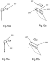
- Figs. 10a, 10b, 11a and 11b show two embodiments of trigger vane and release member combinations.
- the trigger pivot shaft 58 comprises an essentially semi cylindrical shaped release surface 220, and stop means 230 that ensure that the release member 55 enters the correct armed position upon arming the triggering mechanism 3.
- the release member 55 is biased in the direction of the trigger pivot shaft 58 by the lock member 53, which in turn is biased in the opening direction by the loading element 6 via the yoke lever 50.
- the release member 55 In the armed position ( Fig. 8a ), the release member 55 is arranged to apply the biasing force in a direction that is essentially radial to the trigger pivot axis 58.
- the support means is formed by a stop ridge 230 at the lower end of the release surface 220. Moreover, the stop means 230, ensures that the release member 55 rotates together with the trigger pivot shaft 58. In order for the release member 55 to return to the armed position resting upon the trigger pivot shaft 58 upon loading of the actuator mechanism 1, a reset spring member 250 is arranged to bias the release member 55 in the downwards direction ( Fig. 8e ).
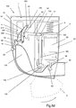
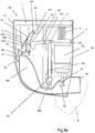
- Figs. 8a to 8f schematically shows the BAI actuator in different states of operation, wherein:
Landscapes
- Health & Medical Sciences (AREA)
- Engineering & Computer Science (AREA)
- Life Sciences & Earth Sciences (AREA)
- Anesthesiology (AREA)
- General Health & Medical Sciences (AREA)
- Biomedical Technology (AREA)
- Heart & Thoracic Surgery (AREA)
- Hematology (AREA)
- Bioinformatics & Cheminformatics (AREA)
- Animal Behavior & Ethology (AREA)
- Pulmonology (AREA)
- Public Health (AREA)
- Veterinary Medicine (AREA)
- Biophysics (AREA)
- Containers And Packaging Bodies Having A Special Means To Remove Contents (AREA)
- Infusion, Injection, And Reservoir Apparatuses (AREA)
- Respiratory Apparatuses And Protective Means (AREA)
- Apparatus Associated With Microorganisms And Enzymes (AREA)
- Nozzles (AREA)
Description
- The present invention relates to an inhaler for delivery of a medicament by inhalation and in particular to the actuation mechanism used in the inhaler to actuate a canister to dispense a dose of medicament.
- Inhalers are commonly used for delivery of a wide range of medicaments. The inhaler holds a canister of medicament, the canister being actuated e.g. by compression to deliver a dose of medicament through a mouthpiece to a user. The inhaler may be provided with an actuation mechanism to actuate the canister automatically and thus dispense a dose of medicament. Some known actuation mechanisms are breath-actuated, so that they operate in response to inhalation by a user. This ensures that a dose of medicament dispensed on actuation of the canister is supplied whilst the user is inhaling. This is particularly useful for those users who may find it difficult to co-ordinate the dispensing of a dose of medicament, by for example, the actuation of a button, with inhaling the dose.
-
US2002/056449 describes a pneumatically actuated inhaler for aerosol medication in which a mechanical lever with attached mouthpiece cover operates a compressor pump which pumps compressed gas into a chamber. -
WO2006115732 describes a breath actuated pulmonary drug delivery device used in the delivery of fluid dispensations from a drug-containing canister. -
WO02/26301 -
EP0049514 discloses an inhaling apparatus with breath-controlled release of the active ingredient, which has sound-damping and movement-damping measures as part of the actuation mechanism. -
WO01/70313 - A known breath-actuated inhaler has an actuation mechanism operable by compression of a canister of medicament to deliver a dose of medicament in response to inhalation by a user. The actuation mechanism comprises a loading mechanism to bias compression of the canister. A triggering mechanism holds the loading mechanism against compression of the canister. When delivery of a dose of medicament is required, the triggering mechanism releases to allow compression of the canister in response to inhalation by the user. An actuating means is connected to a cover for the mouthpiece and is responsive to the closing movement of the cover for re-setting the actuation mechanism. Such an arrangement results in the components of the trigger mechanism not being loaded when the inhaler is not in use. When the cover is closed, critical force is redirected from the triggering mechanism during storage (cap closed). Over time, loading of critical components can quicken the onset of material creep, resulting in mechanical failure of the inhaler and its subsequent inability to deliver a dose of medicament after a number of uses. This situation can be extremely dangerous for the user in an emergency when it is vital that the inhaler deliver a dose when required.
- It is, for reasons mentioned above, an object of the present invention to provide an inhaler incorporating such an actuation mechanism to alleviate the problems described above.
- Accordingly, there is provided an actuator (100) for a breath actuated inhaler, comprising:
- a loading element (6) capable of being loaded with an actuation force,
- a breath actuated trigger mechanism (3) arranged to counteract the actuation force of the loading element (6), and to fire the actuator (100) by releasing the actuation force of the loading element (6) in response to an inhalation breath, and
- actuation locking means (2) moveable between a locked position wherein it relieves the actuation force from the trigger mechanism (3) setting the trigger mechanism (3) in a neutral position, and an armed position wherein the trigger mechanism (3)is set in an armed position
characterized in that - the actuation locking means (2) is formed as a pivotal lever with a helical cam member (110) arranged about a pivotal point (120),
- upon movement of the locking means (2), after the actuator (100) is fired, from its armed position to its locked position, the helical cam member (110) acts on a loading yoke (4), initially to load the loading element (6) with actuation force and to arm the trigger mechanism (3), and subsequently to overload the loading element (6) to relieve the actuation force from the trigger mechanism (3)
- upon subsequent movement of the locking means (2) from its locked position to its armed position, the helical cam member (110) initially acts on the loading yoke (4) to unload the overloading force on the loading element (6) to arm the trigger mechanism (3), where after it is moved to its armed position wherein the helical cam member (110) is in a position that allows firing of the actuator (100), and
- wherein the trigger mechanism (3) comprises:
- a yoke lever (50) arranged to transform the movement of the yoke (4) to a pivotal movement of a lock end (52) thereof,
- a lock member (53) pivotally moveable between an armed position wherein it is arranged to prevent further pivotal movement of the yoke lever lock end (52) in the actuation direction, and an open position wherein the yoke lever (50) is free to move beyond the armed position in the actuation direction, in the armed position the lock member (53) is biased towards the open position by the yoke lever (50) which in turn is biased in the actuation direction by the loading element (6) via the yoke (4),
- a trigger element (57) arranged for movement in response to an inhalation breath, and a release member (55) arranged between the lock member (53) and the trigger element (57) to hold the lock member (53) in the armed position, and to release the lock member (53) in response to movement of the trigger element (57).
- In this way, components of the trigger mechanism and finely toleranced parts are not loaded at any time, either when the inhaler is reset or discharged, except for when the actuator is armed and ready to deliver a dose of medicament. By avoiding heavy loading of the trigger mechanism, the onset of material creep is significantly reduced, resulting in an inhaler that may be re-used more safely.
- Preferably, the loading means further loads the canister with an actuation force for compression of the canister from a rest position to the charging position. Movement of the activating means to the first position applies a force directly to the loading means to compress the canister from the rest position to the charging position. By providing such an arrangement, the canister may be pre-compressed thus reducing the mechanical shock prior to the compressing of the canister to deliver a dose of medicament.
- Preferably, movement of the actuating means between the first position and the second position applies a force directly to the loading means in a direction substantially along the cylindrical axis of the canister.
- Preferably, the loading means comprises a resilient loading element arranged to be loaded with an actuation force, the resilient loading element being arranged when loaded to bias compression of the canister. Typically, the resilient loading element is in a loaded state in which the resilient loading element stores the actuation force.
- The resilient loading element may be a coiled plastic or metal spring. However, alternative arrangements may be envisaged that are able to store and release an actuation force, such as compressed air, a tension spring, an electric motor etc.
- Preferably, the trigger mechanism comprises a lever member and a lever lock member, the lever lock member having a locked position and being so arranged as to hold the lever member in a locked position to hold loading means against compression of the canister.
- Preferably, the latch means comprises a trigger element and a droplink element, movement of the trigger element to its latch release position causes movement of the droplink element to its latch release position, thereby moving the lever lock from its lock position to a release position, causing the lever to move from its locked position to a release position thereby allowing compression of the canister to release a dose of medicament. The droplink element may further comprise a re-set position. This enables the droplink element to readily take up its latch position.
- Alternatively, the trigger element is arranged to be moved to the unlatched position by the application of a manual action by the user into the latch release position described above. For example, a firing button may be provided for manual depression by the user which serves to contact the trigger element to move the trigger element.
- Preferably, the actuation mechanism is breath-actuated, the trigger element being arranged to be moved to the latch release position by inhalation at the mouthpiece to cause operation of the actuation mechanism. The trigger element may be an inhalation responsive trigger vane.
- Preferably, the actuating means is mounted for pivotal movement to apply a force directly to a yoke. The actuating means may be a protective cover or cap (see comment on page 2).
- To allow a better understanding, embodiments of the present invention will now be described, by way of non-limitative examples only, with reference to the accompanying drawings, in which:
-
Fig. 1 is a front perspective view of one embodiment of an inhaler with the actuating means in the open position; -
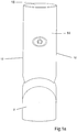
Fig. 1a is a rear perspective view of the inhaler ofFig 1 with the actuating means in the open position; -
Fig. 2 is a side view of the inhaler ofFig 1 with the actuating means in the open position; -
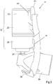
Fig. 3 is a side view of the canister module removed from the inhaler ofFig 1 ; -
Fig. 3a is a front perspective view of the canister module removed from the inhaler ofFig 1 ; -
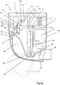
Fig. 4 is a schematic side view of one embodiment of an actuation mechanism in the neutral or "rest" position; -
Fig. 4a is a corresponding perspective view of the actuation mechanism ofFig. 4 in the neutral or "rest" position; -
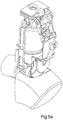
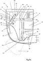
Fig. 5 is a schematic side view of the actuation mechanism ofFig. 4 in the armed or "charging" position; -
Fig. 5a is a corresponding perspective view of the actuation mechanism ofFig. 4 in the armed or "charging" position; -
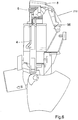
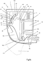
Fig. 6 is a schematic side view of the actuation mechanism ofFig. 4 in the triggered "medicament discharging" position; -
Fig. 6a is a corresponding perspective view of the actuation mechanism ofFig. 4 in the triggered "medicament discharging" position; -
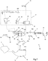
Fig. 7 is an exploded view of the components of the inhaler ofFig. 1 with an actuation mechanism ofFig. 4 . -
Figs. 8a to 8f show schematic side views of a number of states of operation for an embodiment of a breath actuated inhaler (BAI) actuator, with a schematic actuation mechanism. -
Fig. 9 shows an alternative actuation mode for the BAI actuator according toFigs. 8a to 8f . -
Figs. 10a and 10b show perspective views of one embodiment of a release member and a trigger element of a trigger mechanism. -
Figs. 11a and 11b show perspective views of another embodiment of a release member and a trigger element of a trigger mechanism. - Referring now to
Figs. 1 ,1a ,2 and7 , one embodiment of a breath actuated inhaler (BAI)actuator 100, with respect to this embodiment referred to as an inhaler, has ahousing 10 comprisingside walls 12, arear wall 14 and atop wall 16. Therear wall 14 forms a curved surface to facilitate comfortable receipt of the inhaler in the palm of the user's hand. Thewalls housing 10 define a space for accommodating acanister 20 of medicament in achassis 40, and anactuation mechanism 1 so operable as to actuate thecanister 20 to deliver a dose of medicament. Thechassis 40 retains most of the mechanical components of the inhaler in the correct position, and is heavily loaded. For example, most of the components of the trigger mechanism are pivoted on thechassis 40, thus reducing problems caused by tolerance. The front opening in thehousing 10 accommodates a registration module (electronic module) 70 and anupper portion 32 of afacia 30, each having opposedside walls 34, respectively to fit flush with theside walls 12 of thehousing 10. - A
mouthpiece 60 protrudes from thehousing 10 and may be protected from damage and/or the entering of foreign bodies e.g. dust by locking or actuating means 2 pivotally mounted for movement on thechassis 40 as illustrated. In the embodiment shown, the actuating means is aprotective cover 2 and shall now be referred to as such. Thecover 2 has opposed side walls to fit flush with the side walls of thehousing 10, and a rear curved wall to fit flush with the rear wall of thehousing 10. The rear walls of the respective housing and the cover together form a curved surface to facilitate comfortable receipt of the inhaler in the palm of the user's hand. - The
canister 20 fits in thechassis 40 retained in thehousing 10 and may be slidably removed for replacement as illustrated inFigs. 3 and3a . Thecanister 20 is of a known type for holding a suspension or solution of a medicament in a propellant under pressure. Thecanister 20 comprises a generallycylindrical body 22 and avalve stem 24 which are compressible together to deliver a dose of medicament from thevalve stem 24. Thecanister 20 includes a metering chamber (not shown), which captures a defined volume of medicament from thebody 22 of thecanister 20, which volume of medicament is delivered as a metered dose from thevalve stem 24 on compression of the valve stem relative to thebody 22. The valve stem 24 is biased outwardly to reset thecanister 20 after compression for refilling the metering chamber. The valve stem 24 is located in anozzle block 62. Thenozzle block 62 is formed as part of, and in open communication with, themouthpiece 60 to direct a dose of medicament delivered from thevalve stem 24 out of the inhaler through themouthpiece 60. - An opening in the
lower part 36 of thefacia 30 is so sized and shaped as to receive themouthpiece 60, which is of a corresponding size and shape. According to one embodiment, there is provided areplaceable canister module 37 comprising acanister 20 and amouth piece 60 with anozzle block 62, wherein thecanister body 22 is moveable in the actuation direction with respect to thenozzle block 62, and wherein thecanister module 37 is inserted in theactuator 10 in a direction essentially transverse to the actuation direction of the canister. Thecanister 20 is moveably connected to, and supported by, thefacia 30 and themouth piece 60, by acollar 28 fitted around a necked portion of thecanister body 22. Thecollar 28 may be permanently fixed to thecanister 20, and comprises aconnection member 29 that enables a linear motion of thecanister 20 in the actuation direction with respect to thefacia 30 andmouthpiece 60. This allows actuation of the canister by compression of the canister body towards the valve stem when the stem is fixed relative to the inhaler in the nozzle block. In the disclosed embodiment, thecollar 28 has a notched/ 'keyed' inner surface engaging the crimp joining thecanister 20 and valve. In other embodiments, thecanister 20 may be interconnected with thefacia 30 and themouthpiece 60 in another way. Thecanister 20 may be integral with the facia and themouthpiece 60 such that the facia andmouthpiece 60 are removed from the housing and inserted into the housing together with thecanister 20 as acanister module 37 as illustrated inFigs. 3 and3a . When such acanister module 37 is inserted into the housing, themouthpiece 60 stands on a platform in the chassis and encloses the airflow. Themouthpiece 60 forms the end of an air passage through the housing, the inlet of the air passage being adjacent a trigger element. Aclip 38 retains the facia to the housing. The canister and collar have a small degree of movement along the axis of the canister to allow actuation of the canister. - The outer surface of the upper portion of the
facia 30 carries an indication of the type of medicament in thecanister 20 to which thefacia 30 is connected. The indication may be printed information, an embossed or indented pattern, for example, Braille, or the colour of the facia. - The
registration module 70 is responsive to firing of theactuator 100. According to one embodiment theregistration module 70 is arranged to detect the presence of acanister module 37 in the actuator, and arranged to disregard firings of the actuator when nocanister module 37 is present. The detection of acanister module 37 may e.g. be performed by a microswitch (not shown) that is activated when acanister module 37 is inserted into the actuator, eg. by detection of atab 261 extending from the canister module for interaction with said microswich. According to one embodiment, thecanister module 37 comprises anon-use indicator 260 that is preset in a non-use state and which is set in an irreversible in-use state at the first actuation of thecanister module 37. According to one embodiment, thenon-use indicator 260 is a moveable tab, that initially in its non-use state is hidden from detection by theregistration module 70, and upon the first actuation (use) is moved to an exposed "in-use state" where theregistration module 70 detects the presence of the tab. When, the moveable tab has entered the in-use state it is mechanically hindered from returning to its non-use state. Preferably, the moveable tab is hindered from being returned to its non-use mode by tamper proof means. Theregistration module 70 is arranged to detect the state of the of thenon-use indicator 260, e.g. by a second microswitch, each time acanister module 37 is arranged in the actuator, and in response to a: - non-use state; initiate a new actuation counting cycle, and
- in-use state; not count actuations.
- As is evident to any person skilled in the art, the
registration module 70 may be an electronic module or a mechanical counter module with the same or essentially the same functionality. - The
actuation mechanism 1 for actuating thecanister 20 to deliver a dose of medicament is illustrated inFigs. 4 ,4a ,5 ,5a ,6 and6a . Theactuation mechanism 1 operates to compress thecanister body 22 relative to thevalve stem 24 held in thenozzle block 62 to deliver a dose of medicament. The elements illustrated inFigs. 4 ,4a ,5 ,5a ,6 and6a are accommodated in thehousing 10 and retained by thechassis 40 but both thehousing 10 and thechassis 40 are removed fromfigs. 4 ,4a ,5 ,5a ,6 and6a for clarity. - The structure of the
actuation mechanism 1 is as follows. - The
actuation mechanism 1 comprises loading means or aloading element 6 for loading theactuation mechanism 1 with an actuation force for compression of thecanister 20 to deliver a dose of medicament. Aresilient loading element 6, such as a coiled spring is provided for the storage and release of the actuation force. Thecoiled spring 6 is movable in one direction substantially along the cylindrical axis of thecanister 20 to store the actuation force, and in an opposite direction substantially along the cylindrical axis of thecanister 20 to release the actuation force. - The
coiled spring 6 is connected at its lower end to ayoke 4. Theyoke 4 has a canister-engagement portion. A cover element 8 may engage thecoiled spring 6 at its upper end. The cover element 8 may facilitate the spreading of the load on thecoiled spring 6 into thehousing 10 of the inhaler, and may also aid location of thecoiled spring 6 within the housing. - As illustrated in
Figs. 1-3 , the actuation locking means, in the present embodiment represented by thecover 2 is mounted for movement between a first, or open, position relative to thehousing 10, and a second, or closed, position relative to thehousing 10. In the embodiment shown, thecover 2 is pivotally mounted on thechassis 40 and has acam 110 at thepivot point 120. In this way, pivotal movement of thecover 2 to the first or open position allows theyoke 4 to move downwards, under the force applied by thecoiled spring 6. Conversely, pivotal movement of thecover 2 to the second or closed position applies an upward force to theyoke 4 and forces it upwards, compressing thecoiled spring 6. The yoke is thus moveable in a direction substantially along the cylindrical axis of thecanister 20. As a result of the gearing inherent in the cam loading mechanism, the total distance that theyoke 4 performs in response to pivotal movement of thecover 2 is greater than the distance which thecanister body 22 and thevalve stem 24 of thecanister 20 need to be compressed in order to release a dose of medicament. - The
actuation mechanism 1 further includes atrigger mechanism 3 for holding theloading element 6 against compression of thecanister 20. Thetrigger mechanism 3 is constructed as follows. - A yoke lever 50 (lever 50) is pivoted about lever hinge pins 130 that are arranged in mating hinge holes 132 in the
chassis 40 and has a pair oflever arms 51 engaging theyoke 4 in a corresponding pair ofhorizontal yoke groves 140, whereby thelever 50 performs a pivotal movement when theyoke 4 is moved upwards or downwards. At the distal end from thearms 51, thelever 50 has yoke lever lock end in the form of aplanar portion 52 that is arranged to engage alock rib 150 on a lock member 53 (lever lock 53) when thelever lock 53 is in a locked position. Thelever lock 53 is pivoted about lock hinge pins 160 that are arranged in mating hinge holes in thechassis 40. In its locked position, as illustrated inFigs. 5 and5a thelever lock 53 holds the loading means, via thelever 50, against compression of thecanister 20. - The trigger mechanism further comprises latch means in the form of a release member (drop link element) 55 movable between a latch position arranged to store the actuation force to retain the
canister 20 in the rest or charging position, and a latch-release position arranged to release the actuation force and allow compression of thecanister 20. Thedrop link element 55 is pivotally connected at one end to thelever lock 53. Thedrop link 55 is provided at its other end with a latchingelement 56 adapted to engage a trigger element pivotally mounted on the chassis. Thetrigger element 57 is arranged for movement in response to inhalation by the user at the mouthpiece or manual depression by the user of a firing button, to cause actuation of thecanister 20 to deliver a dose of medicament to the mouthpiece. In the embodiment shown, the firing button is made integral with aninlet duct cover 64. However, it may not be made integral therewith. Thefiring button 48 enables the user to deliver a dose of medicament as an emergency function if, for any reason, the usual actuation mechanism fails, or if the user cannot inhale significantly to activate the actuation mechanism to deliver a dose of medicament for example, during a chronic asthma attack. In the preferred embodiment, thetrigger element 57 constitutes an inhalation responsive trigger vane that is an element, which is moved in response to and by a flow of air there over. - The latching
element 56 contacts and rests upon thetrigger vane 57 at itstrigger pivot shaft 58 when thedrop link 55 andtrigger vane 57 are at their latch position. - Operation of the actuation mechanism will now be described with reference to
Figs. 4-6 which illustrate the various parts of the actuation mechanism in schematic form for ease of understanding. -
Fig. 4 illustrates the neutral or "rest" position of the actuation mechanism in which thecover 2 encloses the mouthpiece when the inhaler is not in use. Theyoke 4 is in its uppermost position so that thecoiled spring 6 is in a loaded state, thus storing an actuation force. All mechanical components of the inhaler but theyoke 4 are unloaded and there is no compression of thecanister 20. An air gap exists between the canister engagement portion of theyoke 4 and the base of thecanister 20. However, it can be envisaged that dampening means, such as a foam or rubber element, may be placed between theyoke 4 and thecanister 20. Thelever 50 and thelever lock 53 are both in their locked positions. Thedrop link 55 is in its latched position whereby the latchingelement 56 rests upon thepivot shaft 58 of thetrigger element 57, thereby holding thelever lock 53 in its locked position. - When the inhaler is to be used, the
cover 2 is opened to access the mouthpiece, as shown inFig. 5 . Upon pivotal movement to open thecover 2, theyoke 4 is moved downwardly to engage the base of thecanister 20. In this state, thecoiled spring 6 biases compression of thecanister 20 via theyoke 4, and theyoke 4 compresses thecanister 20 relative to the valve stem a distance of about 0-2 mm. However, further compression of thecanister 20 to deliver a dose of medicament is prevented by the load applied to the trigger mechanism. Thelever lock 53 holds the loading means, via thelever 50, in its locked position, against compression of thecanister 20. Thelever 50 and thelever lock 53 remain in their locked position, the planar portion of thelever 50 being forced against thelock rib 150 on thelever lock 53. In this "armed" or charging state, inhaler is loaded ready for the delivery of a dose of medicament. - Inhalation by the user at the mouthpiece causes air to flow through the air flow path defined inside the housing from the inlet opening to the mouthpiece. Due to the pressure drop created by the flow inside the housing 10 (or use of the firing button as previously described), the
trigger element 57 is caused to pivot in a flow direction to its latch-release position illustrated inFig. 6 . Pivotal movement of thetrigger element 57 to its latch release position causes thedrop link 55 to pivot in an upwards direction to its release position. Pivotal movement of thedrop link 55 in turn causes the latchingelement 56 to be lifted over and to disengage from thepivot shaft 58 of thetrigger element 57. Thepivot shaft 58 of thetrigger element 57 may be substantially circular in cross section, however any shape may be envisaged, such as a sector of a circle, provided that upon rotation of thepivot shaft 58, there is sufficient surface provided to allow the latchingelement 56 to be lifted over and to disengage from thepivot shaft 58. The pivotal movement of thedrop link 55 thus causes thelever lock 53 to pivot in the release direction from its locked or armed position to its release position, to allow compression of the canister by disengagement of theplanar surface 52 from the rib. Thelever 50 in its unlocked state allows compression of thecanister 20 to deliver a dose of medicament under the biasing of thecoiled spring 6. In this state the inhaler may be described as being in its "fired", "triggered" position or "medicament discharging position". - The
lever lock 53 has are-set spring 210 which forces it to pivot back and to return to its latching position. Thedroplink 55 uses anotherspring leg 250 of thesame reset spring 210, however in this case the reset spring allows it to pivot back to return to a reset position ready to take up its latching position. In its reset position, the latchingelement 56 of thedroplink element 55 abuts thepivot shaft 58 of thetrigger element 57. Each of the re-set springs is made from a plastics material or metal. The provision of re-set springs ensures that both thetrigger element 57 and thedroplink 55 are ready to take up or return to their latch position, respectively, without reliance on gravitational force. - Closure of the
cover 2 causes theyoke 4 to move upward, which has three effects. Firstly, it allows thecanister 20 to reset itself. Secondly, it causes thelever 50 and thelever lock 53 to return to their locked position in the neutral position of the actuation mechanism illustrated inFig. 4 , and thedroplink 56 to return its latch position. Thirdly, it stores the actuation force in thecoiled spring 6, via the loading of theyoke 4, ready for when the inhaler is to be used. -
Figs. 8a to 8f show a schematic embodiment of one embodiment of a breath actuated inhaler (BAI) actuator adapted to show the function of the actuation mechanism in detail. The BAI actuator 100 comprises aloading element 6, a breath actuatedtrigger mechanism 3 and actuation locking means 2. - The
loading element 6 provides the force necessary for actuation of the metering valve of the canister, and needs therefore to be capable of being loaded with an actuation force of suitable magnitude. The actuation force required for actuation of the metering valve depends on the type of metering valve and, to some extent, on the type of triggering mechanism. In one embodiment theloading element 6 may be integrated in the metering valve, thus excluding the need for a separate loading element. InFigs. 8a to 8f theloading element 6 is illustrated as a coiled spring, but it may be of any suitable type that is capable of being loaded with the required actuation force. - The breath actuated (BA)
trigger mechanism 3 is arranged to counteract the actuation force of theloading element 6 and to fire theactuator 100 by releasing the actuation force of theloading element 6 in response to an inhalation breath. One example of a BA trigger mechanism is disclosed in detail below, but there are many other types of BA trigger mechanisms that can be used in the present BAI actuator. One example is a mechanism of catch member type, wherein a trigger element is arranged to release a catch member in response to a breath flow. Another example is a mechanism of bistable pivot joint type, wherein a trigger element is pivotal between an armed position wherein it counteracts the actuation force via a pivot joint restricted to a joint angle close to, but less than, 180° and a fired position, wherein the trigger element is arranged to pivot the joint angle beyond 180 ° in response to a breath flow, thereby releasing the actuation force. But other mechanisms or combinations thereof may also be used. - As mentioned above, many components in the trigger mechanism are small sized and often made of plastic material and therefore susceptible to material creep upon prolonged loading. Therefore, the actuator is provided with actuation locking means 2 moveable between a locked position (
Fig. 8f ) wherein it relieves the actuation force from the trigger mechanism setting thetrigger mechanism 3 in a neutral or unloaded position, and an armed position (Fig. 8a ) wherein thetrigger mechanism 3 is set in an armed position. In the disclosed embodiment, the actuation locking means 2 is further arranged to function as actuating means that are arranged to load theloading element 6 with actuation force upon movement from its armed position to its locked position (figs. 8d and8e ), after the actuator is fired. According to one embodiment, not shown in figure, the actuation locking means 2 is provided separately from the actuating means. - In the disclosed embodiment the actuation locking means 2 is formed as a pivotal lever with a
helical cam member 110 arranged about apivotal point 120. Upon movement of the locking means 2 after the actuator is fired, from its armed position (Fig. 8c ) to its locked position (Fig. 8f ), thehelical cam member 110 acts on aloading yoke 4, initially to load theloading element 6 with actuation force (Figs. 8d and8e ) and to arm the trigger mechanism 3 (Fig. 8e ), and subsequently to overload the loading element to relieve the actuation force from thetrigger mechanism 3 setting it in a neutral or unloaded position (Fig. 8f ). Upon subsequent movement of the locking means 2 from its locked position to its armed position, thehelical cam member 110 initially acts on theloading yoke 4 to unload the overloading force on theloading element 6 to arm the trigger mechanism, where after it is moved to its armed position, wherein the helical cam is in a position that allows firing of the actuator (Fig. 8a ). - According to one embodiment, the
helical cam member 110 is formed so that the actuation locking means 2 is retained in the locked position by the actuation force of theloading element 6. In the disclosed embodiment, the helical cam member is formed so that theactive section 170 that is in contact with theyoke 4 is either flat or inclined so that the actuation force gives rise to a stable state or that the actuation locking means 2 is urged in the locked direction. In the disclosed embodiment, the actuation locking means 2 is formed as aprotective cover 2 arranged to limit the access to themouth piece 60 in its locked position and to allow access to the same in its armed position. - In the disclosed embodiment, the BAI actuator is arranged for actuation of a compression firing canister of the type disclosed more in detail above. However, according to other embodiments, the BAI actuator may be arranged for actuation of canisters with other types of metering valves, such as valves that fire upon withdrawal of a control stem, rotary type valves and the like. Moreover, according to one embodiment, the metering valve may be of a type that is biased in the firing direction, and in such case, the biasing force of the metering valve, may be used in lieu of or in combination with the
loading element 6. - In the disclosed embodiment, the
loading element 6 is arranged to act on thecanister body 22 of thecanister 20, and the actuation involves depressing thecanister body 22 of the canister with respect to astatic nozzle block 62. In another embodiment, not disclosed in the figures, theloading element 6 is arranged to act on a moveable nozzle block, wherein actuation involves translation of the nozzle block with respect to thecanister body 22 of thecanister 20 to depress thevalve stem 24. - According to one embodiment the
loading element 6 is arranged to act on the non valve end of thecanister body 22 arranged in theBAI actuator 100, via theyoke 4. In the disclosed embodiment, theloading element 6 is a coiled spring arranged in alignment with the actuation direction of thecanister 20. Theyoke 4 comprises twocam follower legs 180 for cam interaction with, and transmission of, loading translation from thehelical cam 110 to theloading element 6. According to one embodiment, as is exemplified by the embodiment ofFigs. 1 to 7 , thecam follower legs 180 are arranged to extend along diametrically opposite sides of thecanister 20, whereby the force transmitted from the actuation locking means 2 via thehelical cam 110 to theloading element 6 is aligned with actuation direction of thecanister 20. In the embodiment ofFigs. 8a to 8f , theyoke 4 comprises twocam follower legs 180 that are parallel, but not diametrically arranged with respect to thecanister 20, mainly in order to make the figure clearer, but also in order to show that thecam follower legs 180 need not to be in perfect alignment with the actuation direction of the canister. - According to one embodiment, the
trigger mechanism 3, theyoke 4 and the actuation locking means 2, are supported by achassis 40 arranged in anexternal housing 10. As mentioned above, the chassis gives rigidity to the actuator, and by supporting all moveable parts by thechassis 40 problems relating to tolerances between different parts are reduced. InFigs. 8a to 8f thechassis 40 is reduced to a strict illustrative design, to make the function of theactuation mechanism 1 clearer, whereas the embodiment shown inFigs. 1 to 7 comprises achassis 40 that allows a more compact and load efficient design. In the disclosed embodiments, thecam follower legs 180 are arranged for and limited to linear movement inmating yoke grooves 140 formed in thechassis 40. -
Figs. 8a to 8f show one embodiment of a trigger mechanism comprising: - a
yoke lever 50 arranged to transform the movement of theyoke 4 to a pivotal movement of alock end 52 thereof, - a
lock member 53 pivotally moveable between an armed position (Fig. 8a ) wherein it is arranged to prevent further pivotal movement of the yokelever lock end 52 in the actuation direction, and an open position wherein theyoke lever 50 is free to move beyond the armed position in the actuation direction, in the armed position thelock member 53 is biased towards the open position by theyoke lever 52 which in turn is biased in the actuation direction by theloading element 6 via theyoke 4, - a
trigger element 57 arranged for movement in response to an inhalation breath, and - a
release member 55 arranged between thelock member 53 and thetrigger element 57 to hold thelock member 53 in the armed position, and to release thelock member 53 in response to movement of thetrigger element 57. - The
yoke lever 50 is pivotally supported by thechassis 40 by lever hinge pins 130 or the like, and compriseslever arms 51 that are arranged to engagecorresponding yoke grooves 140 formed in theyoke 4. Theyoke lever 50 is formed to create a lever effect gearing down the force applied on the components in the triggering mechanism from theloading element 6. The gearing is achieved in that the longitudinal distance between thehinge pivot point 130 and thelever arms 51 is shorter than the distance between thehinge pivot point 130 and the yokelever lock end 52. In the disclosed embodiment, theyoke lever 50 is arranged so that thelock end 52 performs an upward movement when theyoke 4 moves downwards, but in an alternative embodiment theyoke lever 50 may be formed to reverse the direction of movement by arranging thelever arms 51 in between thehinge pivot point 130 and thelever lock end 52. In the later case, the other parts of the trigger mechanism must be adapted to the reversed direction of movement. - In the disclosed embodiment, the
lock member 53 is pivotally supported by the chassis by lock hinge pins 160. Thelock member 53 comprises alock rib 150 arranged to act as a catch member for thelock end 52 of theyoke lever 50 to arm the triggering mechanism. Thepivot point 160 of thelock member 53, and the interaction between the lock rib and thelock end 52 of theyoke lever 50 are arranged so that thelock member 53 is biased towards the open position by theyoke lever 50. By designing this interaction properly a suitable gear down effect is achieved, reducing the force applied on the components of the trigger mechanism even further. Aspring element 210 biases thelock member 53 in the closing direction, towards theyoke lever 50, in order to reset the trigger mechanism during loading of the actuation mechanism, as is shown inFig. 8d . Theyoke lever 50 comprises a lockmember guide surface 200 at the lock end thereof. As is shown inFigure 8c , the lockmember guide surface 200 interacts with thelock rib 150 to hold the lock member in the open position when the actuator is unloaded. - The
trigger element 57 is arranged at one end of anair flow duct 190 extending from themouth piece 60 at the other end. Theair flow duct 190 may be formed by theactuator housing 10, thechassis 40, or a combination thereof, and optionally with additional components. According to one embodiment, the trigger element is a pivotal vane with atrigger pivot shaft 58 that is pivotally supported by thechassis 40 at a trigger pivotal point and arranged to pivot about a the pivot axis in response to an air flow in the flow duct, e.g. an inhalation breath. Therelease member 55 is, at one end, pivotally connected to the lock member at arelease pivot point 240, and at the other end it is arranged to interact with thetrigger pivot shaft 58 to hold thelock member 53 in the armed position, and to release thelock member 53 in response to pivotal movement of thetrigger pivot shaft 58. According to one embodiment, therelease member 55 is a drop link element. -
Figs. 10a, 10b, 11a and 11b show two embodiments of trigger vane and release member combinations. Thetrigger pivot shaft 58 comprises an essentially semi cylindrical shapedrelease surface 220, and stop means 230 that ensure that therelease member 55 enters the correct armed position upon arming the triggeringmechanism 3. As mentioned above, therelease member 55 is biased in the direction of thetrigger pivot shaft 58 by thelock member 53, which in turn is biased in the opening direction by theloading element 6 via theyoke lever 50. In the armed position (Fig. 8a ), therelease member 55 is arranged to apply the biasing force in a direction that is essentially radial to thetrigger pivot axis 58. When thetrigger vane 57 is pivoted by an air flow in theair flow duct 190, the interaction end of therelease member 55 rotates together with thetrigger pivot shaft 58, and the direction of the biasing force is shifted (lifted) from the trigger pivot axis 58 (Fig. 8b ), and upon sufficient rotation the shifted biasing force makes therelease member 55 detach from its armed state whereby the actuator is fired (Fig. 8c ). InFig. 10a and 10b , stop means 230 of thetrigger pivot shaft 58 are provided on both sides of a semicylindrical release surface 220, and the corresponding release member comprises twostop protrusions 260 that are arranged to abut the stop means 230 of the trigger element. InFigs. 11a and 11b the support means is formed by astop ridge 230 at the lower end of therelease surface 220. Moreover, the stop means 230, ensures that therelease member 55 rotates together with thetrigger pivot shaft 58. In order for therelease member 55 to return to the armed position resting upon thetrigger pivot shaft 58 upon loading of theactuator mechanism 1, areset spring member 250 is arranged to bias therelease member 55 in the downwards direction (Fig. 8e ). -
Figs. 8a to 8f schematically shows the BAI actuator in different states of operation, wherein: -
Fig 8a illustrates the armed state, when the actuator is ready to be fired by an inhalation breath (Figs. 8b and8c ) or by use of thefiring button 48. Theprotective cover 2 which functions as loading means and actuation locking means is in its open or armed position whereby the actuation mechanism is able to be fired. As is discussed in detail above, theloading element 6 is loaded with an actuation force that exceeds the reset bias force in the metering valve of thecanister 20, and the triggeringmechanism 3 counteracts the actuation force via theyoke 4. -
Fig. 8b illustrates an initial phase of a firing of the actuator by an inhalation breath, wherein thetrigger vane 57 is pivoted an amount, but therelease member 55 is still in locking contact with thetrigger pivot shaft 58 and thus prevents firing of the actuator. -
Fig. 8c illustrates the fired state, wherein thetrigger vane 57 is further pivoted and therelease member 55 has been detached from thepivot shaft 58 and thelock member 53 is pivoted to release theyoke lever 50 whereby the actuation force is released and thecanister 20 is depressed to fire a dose of medicament into the inhalation air flow through themouth piece 60. -
Fig. 8d illustrates the process of loading theloading element 6 and arming of thetrigger mechanism 3. Theprotective cover 2 is pivoted in the closing direction, whereby thehelical cam 110 forces theyoke 4 in the loading direction and theyoke lever 50 is pivoted in the armed direction. Thelock rib 150 of thelock member 53 follows theguide surface 200 of theyoke lever 50, biased by thespring element 210. -
Fig. 8e illustrates a state wherein theprotective cover 2 is further pivoted in the closing direction, whereby loading element is essentially fully loaded, and the triggering mechanism has entered its armed state. -
Fig. 8f illustrates the locked state of the actuation mechanism, with theprotective cover 2 closed and wherein thehelical cam 110 is arranged to "over load" theloading element 6 via theyoke 4, whereby the trigger mechanism is unloaded, referred to as the neutral position. - In order to fire the
actuator 100, the cover is pivoted back to the initial state as is illustrated inFig. 8a .
Claims (16)
- Actuator (100) for a breath actuated inhaler, comprising:a loading element (6) capable of being loaded with an actuation force,a breath actuated trigger mechanism (3) arranged to counteract the actuation force of the loading element (6), and to fire the actuator (100) by releasing the actuation force of the loading element (6) in response to an inhalation breath, andactuation locking means (2) moveable between a locked position wherein it relieves the actuation force from the trigger mechanism (3) setting the trigger mechanism (3) in a neutral position, and an armed position wherein the trigger mechanism (3) is set in an armed position,characterized in thatthe actuation locking means (2) is formed as a pivotal lever with a helical cam member (110) arranged about a pivotal point (120),upon movement of the locking means (2), after the actuator (100) is fired, from its armed position to its locked position, the helical cam member (110) acts on a loading yoke (4), initially to load the loading element (6) with actuation force and to arm the trigger mechanism (3), and subsequently to overload the loading element (6) to relieve the actuation force from the trigger mechanism (3)upon subsequent movement of the locking means (2) from its locked position to its armed position, the helical cam member (110) initially acts on the loading yoke (4) to unload the overloading force on the loading element (6) to arm the trigger mechanism (3), where after it is moved to its armed position wherein the helical cam member (110) is in a position that allows firing of the actuator (100), andwherein the trigger mechanism (3) comprises:a yoke lever (50) arranged to transform the movement of the yoke (4) to a pivotal movement of a lock end (52) thereof,a lock member (53) pivotally moveable between an armed position wherein it is arranged to prevent further pivotal movement of the yoke lever lock end (52) in the actuation direction, and an open position wherein the yoke lever (50) is free to move beyond the armed position in the actuation direction, in the armed position the lock member (53) is biased towards the open position by the yoke lever (50) which in turn is biased in the actuation direction by the loading element (6) via the yoke (4),a trigger element (57) arranged for movement in response to an inhalation breath, and a release member (55) arranged between the lock member (53) and the trigger element (57) to hold the lock member (53) in the armed position, and to release the lock member (53) in response to movement of the trigger element (57).
- Actuator (100) according to claim 1 wherein the actuation locking means (2) is arranged to load the loading element (6) upon movement from its armed position to its locked position, after the actuator (100) is fired.
- Actuator (100) according to claim 1 wherein the helical cam member (110) is formed so that the actuation locking means (2) is retained in the locked position by the actuation force of the loading element (6).
- Actuator (100) according to claim 1 wherein the loading element (6) is arranged to act on a non valve end of a canister body (22) of a canister (20) arranged in the actuator (100), via the yoke (4).
- Actuator (100) according to claim 4 wherein the yoke (4) comprises two cam follower legs (180) for cam interaction with and transmission of loading translation from the helical cam member (110) to the loading element (6), the cam follower legs (180) are arranged to extend diametrically along a side of the canister (20).
- Actuator (100) according to claim 1 wherein the trigger mechanism (3), the yoke (4) and the actuation locking means (2) are supported by a chassis (40) arranged in a housing (10).
- Actuator (100) according to claim 5 wherein the trigger mechanism (3), the yoke (4) and the locking means (2) are supported by a chassis (40) arranged in a housing (10), and wherein the cam follower legs (180) are arranged for and limited to linear movement in mating guide grooves formed in the chassis (40).
- Actuator (100) according to claim 1 wherein trigger element (57) is a pivotal vane member.
- Actuator (100) according to claim 8 wherein the release member (55) is a drop link element (55) pivotally attached to the lock member (53) and arranged to engage a release surface of a trigger pivot shaft (58) at the pivotal axis of the vane member in the armed position,
the release member of the vane member and the drop link element (55) are arranged to disengage upon pivotal movement of the vane member, whereby the actuator (100) is fired. - Actuator (100) according to claim 1 wherein the lock member (53) and the release member (55) are biased in the armed direction by one or more spring elements.
- Actuator (100) according to claim 1 comprising a replaceable canister module (37) comprising a canister (20) and a mouth piece (60) with a nozzle block, wherein a canister body (22) is moveable in the actuation direction with respect to the nozzle block, and wherein the canister module (37) is inserted in the actuator (100) in a direction essentially transverse to the actuation direction of the canister (20).
- Actuator (100) according to claim 1 comprising a registration module (70) responsive to firing of the actuator (100).
- Actuator (100) according to claim 11 comprising a registration module (70) responsive to firing of the actuator (100), wherein the registration module (70) is arranged to detect the presence of a canister module(37) in the actuator (100), and arranged to disregard firings of the actuator (100) when no canister module (37) is present.
- Actuator (100) according to claim 13, wherein the canister module (37) comprises a non-use indicator (260) that is present in a non-use state and which is set in a irreversible in-use state at the first actuation of the canister module (37), and wherein the registration module (70) is arranged to detect the state of the non-use indicator (260) each time a canister module (37) is arranged in the actuator (100), and in response to a:non-use state; initiate a new actuation counting cycle, andin-use state; not count actuations.
- Actuator (100) according to claim 1 wherein the actuation locking means (2) is formed as a protective cover arranged to limit the access to a mouth piece (60) in its locked position and to allow access to the same in its armed position.
- Actuator (100) according to claim 1 comprising an air flow duct (190) extending from the trigger element (57) to the mouth piece (60).
Applications Claiming Priority (2)
| Application Number | Priority Date | Filing Date | Title |
|---|---|---|---|
| US88307607P | 2007-01-02 | 2007-01-02 | |
| PCT/SE2008/000005 WO2008082359A1 (en) | 2007-01-02 | 2008-01-02 | Breath actuated inhaler actuator |
Publications (3)
| Publication Number | Publication Date |
|---|---|
| EP2099515A1 EP2099515A1 (en) | 2009-09-16 |
| EP2099515A4 EP2099515A4 (en) | 2017-10-25 |
| EP2099515B1 true EP2099515B1 (en) | 2020-03-18 |
Family
ID=39582180
Family Applications (1)
| Application Number | Title | Priority Date | Filing Date |
|---|---|---|---|
| EP08705181.9A Active EP2099515B1 (en) | 2007-01-02 | 2008-01-02 | Breath actuated inhaler actuator |
Country Status (13)
| Country | Link |
|---|---|
| US (3) | US8225790B2 (en) |
| EP (1) | EP2099515B1 (en) |
| JP (1) | JP5286280B2 (en) |
| KR (2) | KR101487035B1 (en) |
| CN (1) | CN101578118B (en) |
| AU (1) | AU2008203559B2 (en) |
| BR (1) | BRPI0806273B8 (en) |
| CA (1) | CA2674343C (en) |
| ES (1) | ES2796651T3 (en) |
| MX (1) | MX2009006974A (en) |
| NZ (1) | NZ577572A (en) |
| RU (1) | RU2457870C2 (en) |
| WO (1) | WO2008082359A1 (en) |
Families Citing this family (62)
| Publication number | Priority date | Publication date | Assignee | Title |
|---|---|---|---|---|
| USD296605S (en) * | 1985-01-31 | 1988-07-12 | Ecotat System Company | Combination outer garment and tent |
| US8225790B2 (en) | 2007-01-02 | 2012-07-24 | Astrazeneca Ab | Inhaler 624 |
| US8820318B2 (en) * | 2007-08-21 | 2014-09-02 | Glaxo Group Limited | Drug dispenser |
| EP2077132A1 (en) | 2008-01-02 | 2009-07-08 | Boehringer Ingelheim Pharma GmbH & Co. KG | Dispensing device, storage device and method for dispensing a formulation |
| WO2009090245A1 (en) * | 2008-01-16 | 2009-07-23 | Bang & Olufsen Medicom A/S | A dispenser |
| GB2461153A (en) * | 2008-06-25 | 2009-12-30 | Astrazeneca Ab | Inhaler with energy absorbing pads |
| US8578932B2 (en) * | 2008-07-10 | 2013-11-12 | Bang & Olufsen Medicom A/S | Inhaler and a method of operating it |
| EP2414560B1 (en) | 2009-03-31 | 2013-10-23 | Boehringer Ingelheim International GmbH | Method for coating a surface of a component |
| EP3508239B1 (en) | 2009-05-18 | 2020-12-23 | Boehringer Ingelheim International GmbH | Adapter, inhalant apparatus and atomizer |
| EP3031487B1 (en) | 2009-07-30 | 2018-09-12 | Ivax International B.V. | Dose counter for a metered-dose inhaler |
| PL2705868T3 (en) | 2009-07-30 | 2016-04-29 | Ivax Int B V | Dose counter for a metered-dose inhaler |
| CA2769248C (en) | 2009-07-30 | 2014-03-11 | Ivax International B.V. | Pivotal drive member in an inhaler dose counter |
| US10016568B2 (en) | 2009-11-25 | 2018-07-10 | Boehringer Ingelheim International Gmbh | Nebulizer |
| JP5658268B2 (en) | 2009-11-25 | 2015-01-21 | ベーリンガー インゲルハイム インターナショナル ゲゼルシャフト ミット ベシュレンクテル ハフツング | Nebulizer |
| WO2011098798A1 (en) * | 2010-02-10 | 2011-08-18 | Astrazeneca Uk Limited | Process for providing a filled canister for an inhaler |
| ES2707498T3 (en) | 2010-05-18 | 2019-04-03 | Ivax Pharmaceuticals Ireland | Dose counters for inhalers |
| US8689786B2 (en) * | 2010-05-25 | 2014-04-08 | British American Tobacco (Investments) Limited | Aerosol generator |
| JP5874724B2 (en) | 2010-06-24 | 2016-03-02 | ベーリンガー インゲルハイム インターナショナル ゲゼルシャフト ミット ベシュレンクテル ハフツング | Nebulizer |
| US9827384B2 (en) | 2011-05-23 | 2017-11-28 | Boehringer Ingelheim International Gmbh | Nebulizer |
| GB201115874D0 (en) * | 2011-09-14 | 2011-10-26 | Astrazeneca Ab | Inhaler |
| GB201115870D0 (en) * | 2011-09-14 | 2011-10-26 | Astrazeneca Ab | Inhaler |
| WO2013152894A1 (en) | 2012-04-13 | 2013-10-17 | Boehringer Ingelheim International Gmbh | Atomiser with coding means |
| WO2014068504A2 (en) | 2012-10-31 | 2014-05-08 | South Ostrich Ltd. | Systems and methods for administering pulmonary medication |
| WO2014140724A1 (en) * | 2013-03-14 | 2014-09-18 | Trudell Medical International | Metered dose inhaler applicator |
| EP2835146B1 (en) * | 2013-08-09 | 2020-09-30 | Boehringer Ingelheim International GmbH | Nebulizer |
| JP6722112B2 (en) | 2014-04-07 | 2020-07-15 | ベーリンガー インゲルハイム インターナショナル ゲゼルシャフト ミット ベシュレンクテル ハフツング | Method for training and/or controlling a patient's inhalation process, electronic device, inhalation training system and information storage medium |
| AU2015245626B2 (en) * | 2014-04-07 | 2019-10-31 | Boehringer Ingelheim International Gmbh | Inhalation training device and system for practicing of an inhalation process of a patient |
| CN104223362B (en) * | 2014-08-20 | 2017-02-01 | 深圳麦克韦尔股份有限公司 | Inhalator |
| AU2015350319A1 (en) | 2014-11-20 | 2017-06-15 | Cognita Labs, LLC | Method and apparatus to measure, aid and correct the use of inhalers |
| JP6480598B2 (en) | 2015-04-02 | 2019-03-13 | ヒル−ロム サービシーズ プライヴェート リミテッド | Respirator manifold |
| GB2540176A (en) * | 2015-07-08 | 2017-01-11 | Li Jianhe | Dry powder inhaler apparatus |
| KR102641177B1 (en) | 2015-07-20 | 2024-02-26 | 펄 테라퓨틱스 인코포레이티드 | Aerosol delivery systems and related methods |
| USD871567S1 (en) * | 2015-08-07 | 2019-12-31 | Cipla Europe Nv | Inhaler |
| ES2915559T3 (en) * | 2016-02-17 | 2022-06-23 | Adherium Nz Ltd | Adherence monitor for a medication inhaler with cap attached |
| GB201605102D0 (en) | 2016-03-24 | 2016-05-11 | Nicoventures Holdings Ltd | Mechanical connector for electronic vapour provision system |
| US11110234B2 (en) * | 2016-04-05 | 2021-09-07 | Kindeva Drug Delivery L.P. | Medicinal inhaler refill assemblies comprising a lockout mechanism |
| USD808515S1 (en) | 2016-04-05 | 2018-01-23 | 3M Innovative Properties Company | Inhaler |
| US11344684B2 (en) | 2016-04-05 | 2022-05-31 | Kindeva Drug Delivery L.P. | Medicinal inhaler refill assemblies comprising a lockout override mechanism |
| FR3050115B1 (en) * | 2016-04-15 | 2023-05-12 | Aptar France Sas | FLUID PRODUCT DELIVERY DEVICE SYNCHRONIZED WITH INHALATION. |
| FR3050116B1 (en) * | 2016-04-15 | 2020-05-15 | Aptar France Sas | DEVICE FOR DISPENSING SYNCHRONIZED FLUID PRODUCT WITH INHALATION |
| FR3050114B1 (en) * | 2016-04-15 | 2021-12-03 | Aptar France Sas | FLUID PRODUCT DISTRIBUTION DEVICE SYNCHRONIZED WITH INHALATION. |
| GB201615186D0 (en) * | 2016-09-07 | 2016-10-19 | 3M Innovative Properties Co | Energy storage mechanism for an inhaler |
| GB2553534A (en) * | 2016-09-07 | 2018-03-14 | 3M Innovative Properties Co | Trigger mechanism for an inhaler |
| GB2553535A (en) * | 2016-09-07 | 2018-03-14 | 3M Innovative Properties Co | Trigger mechansim for an inhaler |
| GB201702406D0 (en) * | 2017-02-14 | 2017-03-29 | Norton (Waterford) Ltd | Inhalers and related methods |
| GB201702407D0 (en) * | 2017-02-14 | 2017-03-29 | Norton (Waterford) Ltd | Inhalers and related methods |
| GB201706504D0 (en) * | 2017-04-25 | 2017-06-07 | 3M Innovative Properties Co | Medicinal inhaler comprising a lockout override mechanism |
| FR3072294B1 (en) | 2017-10-18 | 2019-10-11 | Aptar France Sas | DEVICE FOR DISPENSING FLUID PRODUCT SYNCHRONIZED WITH INHALATION. |
| FR3072295B1 (en) * | 2017-10-18 | 2019-10-11 | Aptar France Sas | DEVICE FOR DISPENSING FLUID PRODUCT SYNCHRONIZED WITH INHALATION. |
| FR3074051B1 (en) * | 2017-11-29 | 2019-11-22 | Aptar France Sas | DEVICE FOR DISPENSING FLUID PRODUCT SYNCHRONIZED WITH INHALATION |
| IT201800007928A1 (en) * | 2018-08-07 | 2020-02-07 | Sofar Spa | Composition containing a mucolytic agent for the treatment of mucus hypersecretion and a device for its dosage |
| EP3693044A1 (en) * | 2019-02-07 | 2020-08-12 | Koninklijke Philips N.V. | Breath actuated inhalers |
| FR3092251B1 (en) | 2019-02-04 | 2021-01-22 | Aptar France Sas | Fluid dispenser device synchronized with inhalation and method of assembling said device |
| FR3092252B1 (en) * | 2019-02-04 | 2021-01-22 | Aptar France Sas | Fluid dispenser device synchronized with inhalation |
| FR3092250B1 (en) | 2019-02-04 | 2021-01-22 | Aptar France Sas | Fluid dispenser device synchronized with inhalation |
| USD863534S1 (en) * | 2019-07-01 | 2019-10-15 | Optimist Inhaler LLC | Flip-open metered-dose inhaler |
| USD877322S1 (en) * | 2019-08-03 | 2020-03-03 | Optimist Inhaler, LLC | Flip-top metered-dose inhaler |
| US11883582B2 (en) * | 2019-10-17 | 2024-01-30 | Astrazeneca Ab | Inhaler |
| CN113289171B (en) * | 2021-05-25 | 2025-06-27 | 无锡咔噻啨科技发展有限公司 | Inhalation drug delivery device |
| KR102768557B1 (en) * | 2022-07-01 | 2025-02-17 | 주식회사 케이티앤지 | Inhaler |
| CN115040735B (en) * | 2022-07-04 | 2022-11-15 | 上海华瑞气雾剂有限公司 | Cam-type breath-actuated inhaler device |
| CN115120820B (en) * | 2022-07-04 | 2022-12-30 | 上海华瑞气雾剂有限公司 | Lever-type breath-actuated inhaler device |
Family Cites Families (19)
| Publication number | Priority date | Publication date | Assignee | Title |
|---|---|---|---|---|
| DE3037917A1 (en) | 1980-10-08 | 1982-05-13 | Byk Gulden Lomberg Chemische Fabrik Gmbh, 7750 Konstanz | INHALER |
| US5031610A (en) * | 1987-05-12 | 1991-07-16 | Glaxo Inc. | Inhalation device |
| GB9023282D0 (en) * | 1990-10-25 | 1990-12-05 | Riker Laboratories Inc | Inhalation device |
| US5027808A (en) * | 1990-10-31 | 1991-07-02 | Tenax Corporation | Breath-activated inhalation device |
| GB9027234D0 (en) | 1990-12-15 | 1991-02-06 | Harris Pharma Ltd | An inhalation device |
| GB2263873A (en) | 1992-05-29 | 1993-08-11 | Norton Healthcare Ltd | Medicament dispensing device |
| GB9214819D0 (en) * | 1992-07-13 | 1992-08-26 | Minnesota Mining & Mfg | Valve assemblies |
| US6672304B1 (en) * | 1995-06-08 | 2004-01-06 | Innovative Devices, Llc | Inhalation actuated device for use with metered dose inhalers (MDIs) |
| BR9913924A (en) | 1998-09-24 | 2001-06-19 | Astrazeneca Ab | Inhaler for inhalation drug delivery, plurality of inhalers, and container adapted for use in an inhaler |
| GB2360218A (en) | 2000-03-18 | 2001-09-19 | Astrazeneca Uk Ltd | Inhaler |
| GB2360216A (en) * | 2000-03-18 | 2001-09-19 | Astrazeneca Uk Ltd | Inhaler |
| GB0006525D0 (en) * | 2000-03-18 | 2000-05-10 | Astrazeneca Uk Ltd | Inhaler |
| US6637432B2 (en) | 2000-05-09 | 2003-10-28 | Iep Pharmaceutical Devices Inc. | Inhalation actuated device |
| PE20020074A1 (en) * | 2000-06-23 | 2002-02-05 | Norton Healthcare Ltd | DOSING SYSTEM FOR MEDICATION INHALER |
| SE517228C2 (en) * | 2000-09-25 | 2002-05-14 | Microdrug Ag | Dry powder inhaler with respiratory activation |
| DE60141149D1 (en) * | 2000-09-29 | 2010-03-11 | Pfizer Ltd | Medical inhalation device |
| US7575003B2 (en) * | 2002-11-04 | 2009-08-18 | Bang & Olufsen Medicom A/S | Device for dispension |
| US7219664B2 (en) * | 2005-04-28 | 2007-05-22 | Kos Life Sciences, Inc. | Breath actuated inhaler |
| US8225790B2 (en) | 2007-01-02 | 2012-07-24 | Astrazeneca Ab | Inhaler 624 |
-
2007
- 2007-12-21 US US11/962,860 patent/US8225790B2/en active Active
-
2008
- 2008-01-02 BR BRPI0806273A patent/BRPI0806273B8/en active IP Right Grant
- 2008-01-02 NZ NZ577572A patent/NZ577572A/en unknown
- 2008-01-02 KR KR1020097013345A patent/KR101487035B1/en active Active
- 2008-01-02 ES ES08705181T patent/ES2796651T3/en active Active
- 2008-01-02 CN CN2008800016322A patent/CN101578118B/en active Active
- 2008-01-02 WO PCT/SE2008/000005 patent/WO2008082359A1/en not_active Ceased
- 2008-01-02 RU RU2009119914/14A patent/RU2457870C2/en active
- 2008-01-02 EP EP08705181.9A patent/EP2099515B1/en active Active
- 2008-01-02 MX MX2009006974A patent/MX2009006974A/en active IP Right Grant
- 2008-01-02 CA CA2674343A patent/CA2674343C/en active Active
- 2008-01-02 KR KR1020147019207A patent/KR101520593B1/en active Active
- 2008-01-02 AU AU2008203559A patent/AU2008203559B2/en active Active
- 2008-01-02 JP JP2009544822A patent/JP5286280B2/en active Active
-
2012
- 2012-04-19 US US13/450,804 patent/US8800559B2/en active Active
-
2014
- 2014-06-26 US US14/315,625 patent/US9254367B2/en active Active
Non-Patent Citations (1)
| Title |
|---|
| None * |
Also Published As
| Publication number | Publication date |
|---|---|
| NZ577572A (en) | 2011-06-30 |
| JP2010514533A (en) | 2010-05-06 |
| CA2674343A1 (en) | 2008-07-10 |
| EP2099515A1 (en) | 2009-09-16 |
| RU2457870C2 (en) | 2012-08-10 |
| WO2008082359A1 (en) | 2008-07-10 |
| KR101520593B1 (en) | 2015-05-14 |
| RU2009119914A (en) | 2011-02-10 |
| KR20140093756A (en) | 2014-07-28 |
| US20130061850A1 (en) | 2013-03-14 |
| US8800559B2 (en) | 2014-08-12 |
| MX2009006974A (en) | 2009-07-09 |
| AU2008203559A1 (en) | 2008-07-10 |
| CN101578118B (en) | 2013-08-14 |
| CN101578118A (en) | 2009-11-11 |
| KR20090094111A (en) | 2009-09-03 |
| US20080156321A1 (en) | 2008-07-03 |
| BRPI0806273B1 (en) | 2019-03-26 |
| KR101487035B1 (en) | 2015-01-27 |
| US20150122249A1 (en) | 2015-05-07 |
| ES2796651T3 (en) | 2020-11-27 |
| US8225790B2 (en) | 2012-07-24 |
| AU2008203559B2 (en) | 2011-03-17 |
| CA2674343C (en) | 2015-05-12 |
| EP2099515A4 (en) | 2017-10-25 |
| JP5286280B2 (en) | 2013-09-11 |
| BRPI0806273A2 (en) | 2011-09-06 |
| BRPI0806273B8 (en) | 2021-06-22 |
| US9254367B2 (en) | 2016-02-09 |
Similar Documents
| Publication | Publication Date | Title |
|---|---|---|
| US9254367B2 (en) | Inhaler 624 | |
| AU772556B2 (en) | Inhaler | |
| AU2001239648B2 (en) | Inhaler | |
| US6823863B2 (en) | Inhaler | |
| AU2001244903B2 (en) | Inhaler | |
| US6860262B2 (en) | Inhaler | |
| WO2015150734A1 (en) | Inhaler device | |
| AU2001244905B2 (en) | Inhaler | |
| AU2001244905A1 (en) | Inhaler | |
| HK1134659B (en) | Breath actuated inhaler actuator |
Legal Events
| Date | Code | Title | Description |
|---|---|---|---|
| PUAI | Public reference made under article 153(3) epc to a published international application that has entered the european phase |
Free format text: ORIGINAL CODE: 0009012 |
|
| 17P | Request for examination filed |
Effective date: 20090612 |
|
| AK | Designated contracting states |
Kind code of ref document: A1 Designated state(s): AT BE BG CH CY CZ DE DK EE ES FI FR GB GR HR HU IE IS IT LI LT LU LV MC MT NL NO PL PT RO SE SI SK TR |
|
| DAX | Request for extension of the european patent (deleted) | ||
| REG | Reference to a national code |
Ref country code: HK Ref legal event code: DE Ref document number: 1134659 Country of ref document: HK |
|
| STAA | Information on the status of an ep patent application or granted ep patent |
Free format text: STATUS: EXAMINATION IS IN PROGRESS |
|
| RA4 | Supplementary search report drawn up and despatched (corrected) |
Effective date: 20170922 |
|
| RIC1 | Information provided on ipc code assigned before grant |
Ipc: A61M 15/00 20060101AFI20170918BHEP |
|
| 17Q | First examination report despatched |
Effective date: 20171018 |
|
| GRAP | Despatch of communication of intention to grant a patent |
Free format text: ORIGINAL CODE: EPIDOSNIGR1 |
|
| STAA | Information on the status of an ep patent application or granted ep patent |
Free format text: STATUS: GRANT OF PATENT IS INTENDED |
|
| INTG | Intention to grant announced |
Effective date: 20191212 |
|
| GRAS | Grant fee paid |
Free format text: ORIGINAL CODE: EPIDOSNIGR3 |
|
| GRAA | (expected) grant |
Free format text: ORIGINAL CODE: 0009210 |
|
| STAA | Information on the status of an ep patent application or granted ep patent |
Free format text: STATUS: THE PATENT HAS BEEN GRANTED |
|
| AK | Designated contracting states |
Kind code of ref document: B1 Designated state(s): AT BE BG CH CY CZ DE DK EE ES FI FR GB GR HR HU IE IS IT LI LT LU LV MC MT NL NO PL PT RO SE SI SK TR |
|
| REG | Reference to a national code |
Ref country code: GB Ref legal event code: FG4D |
|
| REG | Reference to a national code |
Ref country code: DE Ref legal event code: R096 Ref document number: 602008062321 Country of ref document: DE |
|
| REG | Reference to a national code |
Ref country code: AT Ref legal event code: REF Ref document number: 1245203 Country of ref document: AT Kind code of ref document: T Effective date: 20200415 Ref country code: IE Ref legal event code: FG4D |
|
| REG | Reference to a national code |
Ref country code: NL Ref legal event code: FP |
|
| REG | Reference to a national code |
Ref country code: SE Ref legal event code: TRGR |
|
| PG25 | Lapsed in a contracting state [announced via postgrant information from national office to epo] |
Ref country code: NO Free format text: LAPSE BECAUSE OF FAILURE TO SUBMIT A TRANSLATION OF THE DESCRIPTION OR TO PAY THE FEE WITHIN THE PRESCRIBED TIME-LIMIT Effective date: 20200618 Ref country code: FI Free format text: LAPSE BECAUSE OF FAILURE TO SUBMIT A TRANSLATION OF THE DESCRIPTION OR TO PAY THE FEE WITHIN THE PRESCRIBED TIME-LIMIT Effective date: 20200318 |
|
| PG25 | Lapsed in a contracting state [announced via postgrant information from national office to epo] |
Ref country code: BG Free format text: LAPSE BECAUSE OF FAILURE TO SUBMIT A TRANSLATION OF THE DESCRIPTION OR TO PAY THE FEE WITHIN THE PRESCRIBED TIME-LIMIT Effective date: 20200618 Ref country code: GR Free format text: LAPSE BECAUSE OF FAILURE TO SUBMIT A TRANSLATION OF THE DESCRIPTION OR TO PAY THE FEE WITHIN THE PRESCRIBED TIME-LIMIT Effective date: 20200619 Ref country code: HR Free format text: LAPSE BECAUSE OF FAILURE TO SUBMIT A TRANSLATION OF THE DESCRIPTION OR TO PAY THE FEE WITHIN THE PRESCRIBED TIME-LIMIT Effective date: 20200318 Ref country code: LV Free format text: LAPSE BECAUSE OF FAILURE TO SUBMIT A TRANSLATION OF THE DESCRIPTION OR TO PAY THE FEE WITHIN THE PRESCRIBED TIME-LIMIT Effective date: 20200318 |
|
| REG | Reference to a national code |
Ref country code: LT Ref legal event code: MG4D |
|
| PG25 | Lapsed in a contracting state [announced via postgrant information from national office to epo] |
Ref country code: SK Free format text: LAPSE BECAUSE OF FAILURE TO SUBMIT A TRANSLATION OF THE DESCRIPTION OR TO PAY THE FEE WITHIN THE PRESCRIBED TIME-LIMIT Effective date: 20200318 Ref country code: IS Free format text: LAPSE BECAUSE OF FAILURE TO SUBMIT A TRANSLATION OF THE DESCRIPTION OR TO PAY THE FEE WITHIN THE PRESCRIBED TIME-LIMIT Effective date: 20200718 Ref country code: CZ Free format text: LAPSE BECAUSE OF FAILURE TO SUBMIT A TRANSLATION OF THE DESCRIPTION OR TO PAY THE FEE WITHIN THE PRESCRIBED TIME-LIMIT Effective date: 20200318 Ref country code: PT Free format text: LAPSE BECAUSE OF FAILURE TO SUBMIT A TRANSLATION OF THE DESCRIPTION OR TO PAY THE FEE WITHIN THE PRESCRIBED TIME-LIMIT Effective date: 20200812 Ref country code: RO Free format text: LAPSE BECAUSE OF FAILURE TO SUBMIT A TRANSLATION OF THE DESCRIPTION OR TO PAY THE FEE WITHIN THE PRESCRIBED TIME-LIMIT Effective date: 20200318 Ref country code: LT Free format text: LAPSE BECAUSE OF FAILURE TO SUBMIT A TRANSLATION OF THE DESCRIPTION OR TO PAY THE FEE WITHIN THE PRESCRIBED TIME-LIMIT Effective date: 20200318 Ref country code: EE Free format text: LAPSE BECAUSE OF FAILURE TO SUBMIT A TRANSLATION OF THE DESCRIPTION OR TO PAY THE FEE WITHIN THE PRESCRIBED TIME-LIMIT Effective date: 20200318 |
|
| REG | Reference to a national code |
Ref country code: AT Ref legal event code: MK05 Ref document number: 1245203 Country of ref document: AT Kind code of ref document: T Effective date: 20200318 |
|
| REG | Reference to a national code |
Ref country code: ES Ref legal event code: FG2A Ref document number: 2796651 Country of ref document: ES Kind code of ref document: T3 Effective date: 20201127 |
|
| REG | Reference to a national code |
Ref country code: DE Ref legal event code: R097 Ref document number: 602008062321 Country of ref document: DE |
|
| PLBE | No opposition filed within time limit |
Free format text: ORIGINAL CODE: 0009261 |
|
| STAA | Information on the status of an ep patent application or granted ep patent |
Free format text: STATUS: NO OPPOSITION FILED WITHIN TIME LIMIT |
|
| PG25 | Lapsed in a contracting state [announced via postgrant information from national office to epo] |
Ref country code: DK Free format text: LAPSE BECAUSE OF FAILURE TO SUBMIT A TRANSLATION OF THE DESCRIPTION OR TO PAY THE FEE WITHIN THE PRESCRIBED TIME-LIMIT Effective date: 20200318 Ref country code: AT Free format text: LAPSE BECAUSE OF FAILURE TO SUBMIT A TRANSLATION OF THE DESCRIPTION OR TO PAY THE FEE WITHIN THE PRESCRIBED TIME-LIMIT Effective date: 20200318 |
|
| 26N | No opposition filed |
Effective date: 20201221 |
|
| PG25 | Lapsed in a contracting state [announced via postgrant information from national office to epo] |
Ref country code: PL Free format text: LAPSE BECAUSE OF FAILURE TO SUBMIT A TRANSLATION OF THE DESCRIPTION OR TO PAY THE FEE WITHIN THE PRESCRIBED TIME-LIMIT Effective date: 20200318 |
|
| PG25 | Lapsed in a contracting state [announced via postgrant information from national office to epo] |
Ref country code: SI Free format text: LAPSE BECAUSE OF FAILURE TO SUBMIT A TRANSLATION OF THE DESCRIPTION OR TO PAY THE FEE WITHIN THE PRESCRIBED TIME-LIMIT Effective date: 20200318 |
|
| PG25 | Lapsed in a contracting state [announced via postgrant information from national office to epo] |
Ref country code: MC Free format text: LAPSE BECAUSE OF FAILURE TO SUBMIT A TRANSLATION OF THE DESCRIPTION OR TO PAY THE FEE WITHIN THE PRESCRIBED TIME-LIMIT Effective date: 20200318 |
|
| PG25 | Lapsed in a contracting state [announced via postgrant information from national office to epo] |
Ref country code: LU Free format text: LAPSE BECAUSE OF NON-PAYMENT OF DUE FEES Effective date: 20210102 |
|
| REG | Reference to a national code |
Ref country code: BE Ref legal event code: MM Effective date: 20210131 |
|
| PG25 | Lapsed in a contracting state [announced via postgrant information from national office to epo] |
Ref country code: IE Free format text: LAPSE BECAUSE OF NON-PAYMENT OF DUE FEES Effective date: 20210102 |
|
| PG25 | Lapsed in a contracting state [announced via postgrant information from national office to epo] |
Ref country code: BE Free format text: LAPSE BECAUSE OF NON-PAYMENT OF DUE FEES Effective date: 20210131 |
|
| PG25 | Lapsed in a contracting state [announced via postgrant information from national office to epo] |
Ref country code: HU Free format text: LAPSE BECAUSE OF FAILURE TO SUBMIT A TRANSLATION OF THE DESCRIPTION OR TO PAY THE FEE WITHIN THE PRESCRIBED TIME-LIMIT; INVALID AB INITIO Effective date: 20080102 Ref country code: CY Free format text: LAPSE BECAUSE OF FAILURE TO SUBMIT A TRANSLATION OF THE DESCRIPTION OR TO PAY THE FEE WITHIN THE PRESCRIBED TIME-LIMIT Effective date: 20200318 |
|
| P01 | Opt-out of the competence of the unified patent court (upc) registered |
Effective date: 20230329 |
|
| PG25 | Lapsed in a contracting state [announced via postgrant information from national office to epo] |
Ref country code: MT Free format text: LAPSE BECAUSE OF FAILURE TO SUBMIT A TRANSLATION OF THE DESCRIPTION OR TO PAY THE FEE WITHIN THE PRESCRIBED TIME-LIMIT Effective date: 20200318 |
|
| PGFP | Annual fee paid to national office [announced via postgrant information from national office to epo] |
Ref country code: GB Payment date: 20251217 Year of fee payment: 19 |
|
| PGFP | Annual fee paid to national office [announced via postgrant information from national office to epo] |
Ref country code: NL Payment date: 20251217 Year of fee payment: 19 Ref country code: FR Payment date: 20251217 Year of fee payment: 19 |
|
| PGFP | Annual fee paid to national office [announced via postgrant information from national office to epo] |
Ref country code: SE Payment date: 20251217 Year of fee payment: 19 |
|
| REG | Reference to a national code |
Ref country code: CH Ref legal event code: U11 Free format text: ST27 STATUS EVENT CODE: U-0-0-U10-U11 (AS PROVIDED BY THE NATIONAL OFFICE) Effective date: 20260201 |
|
| PGFP | Annual fee paid to national office [announced via postgrant information from national office to epo] |
Ref country code: ES Payment date: 20260202 Year of fee payment: 19 |
|
| PGFP | Annual fee paid to national office [announced via postgrant information from national office to epo] |
Ref country code: DE Payment date: 20251217 Year of fee payment: 19 |
|
| PGFP | Annual fee paid to national office [announced via postgrant information from national office to epo] |
Ref country code: IT Payment date: 20260107 Year of fee payment: 19 |
|
| PGFP | Annual fee paid to national office [announced via postgrant information from national office to epo] |
Ref country code: TR Payment date: 20260102 Year of fee payment: 19 |
|
| PGFP | Annual fee paid to national office [announced via postgrant information from national office to epo] |
Ref country code: CH Payment date: 20260201 Year of fee payment: 19 |