EP2099143A1 - Emitter with pilot signal synchronisation - Google Patents
Emitter with pilot signal synchronisation Download PDFInfo
- Publication number
- EP2099143A1 EP2099143A1 EP20090154135 EP09154135A EP2099143A1 EP 2099143 A1 EP2099143 A1 EP 2099143A1 EP 20090154135 EP20090154135 EP 20090154135 EP 09154135 A EP09154135 A EP 09154135A EP 2099143 A1 EP2099143 A1 EP 2099143A1
- Authority
- EP
- European Patent Office
- Prior art keywords
- pilot
- frame synchronization
- words
- channel
- illustrates
- Prior art date
- Legal status (The legal status is an assumption and is not a legal conclusion. Google has not performed a legal analysis and makes no representation as to the accuracy of the status listed.)
- Granted
Links
Images


Classifications
-
- H—ELECTRICITY
- H04—ELECTRIC COMMUNICATION TECHNIQUE
- H04B—TRANSMISSION
- H04B1/00—Details of transmission systems, not covered by a single one of groups H04B3/00 - H04B13/00; Details of transmission systems not characterised by the medium used for transmission
- H04B1/69—Spread spectrum techniques
- H04B1/707—Spread spectrum techniques using direct sequence modulation
- H04B1/7073—Synchronisation aspects
-
- H—ELECTRICITY
- H04—ELECTRIC COMMUNICATION TECHNIQUE
- H04L—TRANSMISSION OF DIGITAL INFORMATION, e.g. TELEGRAPHIC COMMUNICATION
- H04L25/00—Baseband systems
- H04L25/02—Details ; arrangements for supplying electrical power along data transmission lines
- H04L25/0202—Channel estimation
- H04L25/0224—Channel estimation using sounding signals
- H04L25/0226—Channel estimation using sounding signals sounding signals per se
-
- H—ELECTRICITY
- H04—ELECTRIC COMMUNICATION TECHNIQUE
- H04B—TRANSMISSION
- H04B1/00—Details of transmission systems, not covered by a single one of groups H04B3/00 - H04B13/00; Details of transmission systems not characterised by the medium used for transmission
- H04B1/69—Spread spectrum techniques
- H04B1/707—Spread spectrum techniques using direct sequence modulation
- H04B1/7073—Synchronisation aspects
- H04B1/7075—Synchronisation aspects with code phase acquisition
-
- H—ELECTRICITY
- H04—ELECTRIC COMMUNICATION TECHNIQUE
- H04L—TRANSMISSION OF DIGITAL INFORMATION, e.g. TELEGRAPHIC COMMUNICATION
- H04L25/00—Baseband systems
- H04L25/02—Details ; arrangements for supplying electrical power along data transmission lines
- H04L25/0202—Channel estimation
- H04L25/0224—Channel estimation using sounding signals
-
- H—ELECTRICITY
- H04—ELECTRIC COMMUNICATION TECHNIQUE
- H04L—TRANSMISSION OF DIGITAL INFORMATION, e.g. TELEGRAPHIC COMMUNICATION
- H04L5/00—Arrangements affording multiple use of the transmission path
- H04L5/003—Arrangements for allocating sub-channels of the transmission path
- H04L5/0048—Allocation of pilot signals, i.e. of signals known to the receiver
-
- H—ELECTRICITY
- H04—ELECTRIC COMMUNICATION TECHNIQUE
- H04W—WIRELESS COMMUNICATION NETWORKS
- H04W56/00—Synchronisation arrangements
-
- H—ELECTRICITY
- H04—ELECTRIC COMMUNICATION TECHNIQUE
- H04B—TRANSMISSION
- H04B1/00—Details of transmission systems, not covered by a single one of groups H04B3/00 - H04B13/00; Details of transmission systems not characterised by the medium used for transmission
- H04B1/69—Spread spectrum techniques
- H04B1/707—Spread spectrum techniques using direct sequence modulation
- H04B1/7073—Synchronisation aspects
- H04B1/7075—Synchronisation aspects with code phase acquisition
- H04B1/70755—Setting of lock conditions, e.g. threshold
-
- H—ELECTRICITY
- H04—ELECTRIC COMMUNICATION TECHNIQUE
- H04B—TRANSMISSION
- H04B1/00—Details of transmission systems, not covered by a single one of groups H04B3/00 - H04B13/00; Details of transmission systems not characterised by the medium used for transmission
- H04B1/69—Spread spectrum techniques
- H04B1/707—Spread spectrum techniques using direct sequence modulation
- H04B1/709—Correlator structure
- H04B1/7095—Sliding correlator type
-
- H—ELECTRICITY
- H04—ELECTRIC COMMUNICATION TECHNIQUE
- H04B—TRANSMISSION
- H04B1/00—Details of transmission systems, not covered by a single one of groups H04B3/00 - H04B13/00; Details of transmission systems not characterised by the medium used for transmission
- H04B1/69—Spread spectrum techniques
- H04B1/707—Spread spectrum techniques using direct sequence modulation
- H04B1/7097—Interference-related aspects
- H04B1/711—Interference-related aspects the interference being multi-path interference
- H04B1/7115—Constructive combining of multi-path signals, i.e. RAKE receivers
-
- H—ELECTRICITY
- H04—ELECTRIC COMMUNICATION TECHNIQUE
- H04B—TRANSMISSION
- H04B2201/00—Indexing scheme relating to details of transmission systems not covered by a single group of H04B3/00 - H04B13/00
- H04B2201/69—Orthogonal indexing scheme relating to spread spectrum techniques in general
- H04B2201/707—Orthogonal indexing scheme relating to spread spectrum techniques in general relating to direct sequence modulation
- H04B2201/70701—Orthogonal indexing scheme relating to spread spectrum techniques in general relating to direct sequence modulation featuring pilot assisted reception
-
- H—ELECTRICITY
- H04—ELECTRIC COMMUNICATION TECHNIQUE
- H04B—TRANSMISSION
- H04B7/00—Radio transmission systems, i.e. using radiation field
- H04B7/24—Radio transmission systems, i.e. using radiation field for communication between two or more posts
- H04B7/26—Radio transmission systems, i.e. using radiation field for communication between two or more posts at least one of which is mobile
- H04B7/2662—Arrangements for Wireless System Synchronisation
- H04B7/2668—Arrangements for Wireless Code-Division Multiple Access [CDMA] System Synchronisation
-
- H—ELECTRICITY
- H04—ELECTRIC COMMUNICATION TECHNIQUE
- H04J—MULTIPLEX COMMUNICATION
- H04J13/00—Code division multiplex systems
- H04J13/16—Code allocation
- H04J13/18—Allocation of orthogonal codes
Definitions
- the present invention relates to communication systems, and more particularly, cellular communication systems.
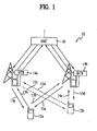
- FIG. 1 generally illustrates a system 10, which uses CDMA modulation techniques in communication between user equipment (UE) 12a and 12b, each UE including a cellular telephone, and base stations (BTS) 14a and 14b.
- a base station controller (BSC) 16 typically includes an interface and processing circuitry for providing system control to the BTS 14a, 14b.
- the BSC 16 controls the routing of telephone calls from the public switched telephone network (PSTN) to the appropriate BTS for transmission to the appropriate UE.
- PSTN public switched telephone network
- the BSC 16 also controls the routing of calls from the UEs, via at least one BTS to the PSTN.
- the BSC 16 may direct calls between UEs via the appropriate BTS since UEs do not typically communicate directly with one another.
- the BSC 16 may be coupled to the BTS 14a and 14b by various means including dedicated telephone lines, optical fiber links or by microwave communication links.
- the arrows 13a-13d define the possible communication links between the BTS 14a and UEs 12a and 12b.
- the arrows 15a-15d define the possible communication links between the BTS 14ba and UEs 12a and 12b.
- the UE signals is received by BTS 14a and/or BTS 14b, which, after demodulation and combining, pass the signal forward to the combining point, typically to the BSC 16.
- the BTS signals are received by UE 12a and/or UE 12b.
- the above system is described in U.S. Patent Nos. 5,101,501 ; 5,103,459 ; 5,109,390 ; and 5,416,797 , whose entire disclosure is hereby incorporated by reference therein.
- a radio channel is a generally hostile medium in nature. It is rather difficult to predict its behavior.
- the radio channels are modeled in a statistical way using real propagation measurement data.
- the signal fading in a radio environment can be decomposed into a large-scale path loss component together with a medium-scale slow varying component having a log-normal distribution, and a small-scale fast varying component with a Rician or Rayleigh distribution, depending on the presence or absence of the line-of-sight (LOS) situation between the transmitter and the receiver.
- LOS line-of-sight
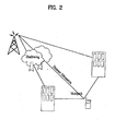
- Figure 2 illustrates these three different propagation phenomena.
- An extreme variation in the transmission path between the transmitter and receiver can be found, ranging from direct LOS to severely obstructed paths due to buildings, mountains, or foliage.
- the phenomenon of decreasing received power with distance due to reflection, diffraction around structures, and refraction is known as path loss.
- the transmitted signal is reflected by many obstacles between a transmitter and a receiver, thus creating a multipath channel. Due to the interference among many multipaths with different time delays, the received signal suffers from frequency selective multipath fading. For example, when the 2GHz carrier frequency band is used and a car having a UE is travelling at a speed of 100km/h, the maximum Doppler frequency of fading is 185Hz. While coherent detection can be used to increase link capacity, under such fast fading, the channel estimation for coherent detection is generally very difficult to achieve. Because of fading channels, it is hard to obtain a phase reference for the coherent detection of data modulated signal. Therefore, it is beneficial to have a separate pilot channel.
- a channel estimate for coherent detection is obtained from a common pilot channel.
- a common pilot channel transmitted with an omnidirectional antenna experiences a different radio channel than a traffic channel signal transmitted through a narrow beam.
- common control channels are often problematic in the downlink when adaptive antennas are used.
- the problem can be circumvented by user dedicated pilot symbols, which are used as a reference signal for the channel estimation.
- the dedicated pilot symbols can either be time or code multiplexed.
- Figure 3 depicts a block diagram of a transmitter and a receiver for time multiplexed pilot symbols for an improved channel estimation method that works satisfactorily under slow-to-fast fading environments.
- Known pilot symbols are periodically multiplexed with the sequence of the transmitted data.
- the pilot symbols and data symbols following pilot symbols constitute a slot, as shown in Figure 3 .
- the information signal is modulated by a spreading code, and in the receiver, it is correlated with a replica of the same code.
- a spreading code in the receiver, it is correlated with a replica of the same code.
- low cross-correlation between the desired and interfering users is important to suppress the multiple access interference.
- Good autocorrelation properties are required for reliable initial synchronization, since large sidelobes of the autocorrelation function may lead to erroneous code synchronization decisions.
- good autocorrelation properties are important to reliably separate the multipath components.
- the DS code sequences are also called pseudo-noise (PN) sequences.
- PN pseudo-noise
- the autocorrelation and cross-correlation functions are connected in such a way that it is not possible to achieve good autocorrelation and cross-correlation values simultaneously. This can be intuitively explained by noting that having good autocorrelation properties is also an indication of good randomness of a sequence. Random codes exhibit worse cross-correlation properties than deterministic codes.
- GSM Global System for Mobile Communications
- PDC Personal Digital Cellular
- IS-95 IS-95 in the United States belonged to the second generation.
- IMT-2000 International Mobile Telecommunications - 2000
- UMTS Universal Mobile Telecommunication System
- Wideband CDMA has emerged as the mainstream air interface solution for the third generation networks.
- Wideband CDMA systems are currently being standardized by the European Telecommunications Standards Institute (ETSI) of Europe, the Association for Radio Industry and Business (ARIB) of Japan, the TIA Engineering Committees TR45 and TR46 and the T1 committee T1P1 of the United States, and the Telecommunication Technology Association TTA I and TTA II (renamed Global CDMA I and II, respectively) in Korea.
- ETSI European Telecommunications Standards Institute
- ARIB Association for Radio Industry and Business
- T1P1 the T1 committee
- T1P1 Telecommunication Technology Association
- ARIB in Japan, ETSI in Europe, T1 in U.S.A., and TTA in Korea have mapped out a third generation mobile communication system based on a core network and radio access technique of an existing global system for mobile communications (GSM) to provide various services including multimedia, such as audio, video and data.
- GSM global system for mobile communications
- They have agreed to a partnership study for the presentation of a technical specification on the evolved next generation mobile communication system and named a project for the partnership study as a third generation partnership project (3GPP).
- the 3GPP is classified into three part technical studies.
- the first part is a 3GPP system structure and service capability based on the 3GPP specification.
- the second part is a study of a universal terrestrial radio access network (UTRAN), which is a radio access network (RAN) applying wideband CDMA technique based on a frequency division duplex (FDD) mode, and a TD-CDMA technique based on a time division duplex (TDD) mode.
- UTRAN universal terrestrial radio access network
- RAN radio access network
- FDD frequency division duplex
- TDD time division duplex
- the third part is a study of a core network evolved from a second generation GSM, which has third generation networking capabilities, such as mobility management and global roaming.
- the physical channel includes the dedicated physical channels (DPCHs) used in the uplink and downlink.
- DPCH dedicated physical channels
- Each DPCH is generally provided with three layers, e.g., superframes, radio frames and timeslots.
- a superframe has a maximum frame unit of 720ms period.
- one superframe is composed of seventy-two radio frames.
- Each radio frame has a period of 10ms, and a radio frame includes sixteen timeslots, each of which includes fields with corresponding information bits based on the DPCH.
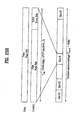
- FIG. 4 illustrates a frame structure of an uplink DPCH based on the 3GPP RAN standard.
- the uplink DPCH is provided with two types of channels, e.g., a dedicated physical data channel (DPDCH) and a dedicated physical control channel (DPCCH).
- DPDCH dedicated physical data channel
- DPCCH dedicated physical control channel
- the uplink DPDCH is adapted to transport the dedicated data
- the uplink DPCCH is adapted to transport the control information.
- the uplink DPCCH for the transport of the control information includes various fields such as a pilot field 21 of N pilot bits, a transmit power-control (TPC) field 22 of N TPC bits, a feedback information (FBI) field 23 of N FBI bits and an optional transport-combination indicator (TFCI) field 24 of N TFCI bits.
- the pilot field 21 includes pilot bits N pilot for supporting channel estimation for coherent detection.
- the TFCI field 4 supports the simultaneous provision of a plurality of services by the system. The absence of the TFCI field 4 in the uplink DPCCH signifies that the associated service is a fixed rate service.
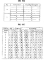
- Figure 5 is a table showing various information of the uplink DPCCH, wherein channel bit and symbol rates are those just prior to spreading. (At the time of this technical specification, the exact number of bits of the different uplink DPCCH fields of Figure 4 (N pilot, N TPC, N FBI, and N TFCI ) was not determined.)
- Figure 6 is a table illustrating pilot bit patterns of the uplink DPCCH, and more particularly, 6-bit and 8-bit pilot bit patterns for each slot
- the non-shaded sequence is used for channel estimation, and shaded sequence can be used as frame synchronization words or sequences.
- the pilot bits other than frame synchronization word, e.g., channel estimation word, have a value of 1.
- the sequences at bit #1, at bit #3, at bit #5, and at bit #7 are used as the frame synchronization words.
- the pilot bits of each sequences slot are either 6 or 8 in number, a total of four is used as the frame synchronization word.
- the number of pilot bits used as the frame synchronization word is 64 bits per frame.
- Figure 7 shows a spreading/scrambling arrangement for the uplink DPCH based on the 3GPP RAN standard.
- the arrangement of Figure 7 is provided for the execution of a quadrature phase shift keying (QPSK) operation where the uplink DPDCH and DPCCH are mapped into I and Q channel branches, respectively.
- QPSK quadrature phase shift keying
- the spreading is an operation for switching all symbols through the respective channel branches to a plurality of chips.
- the I and Q channel branches are spread respectively at chip rates based on two different orthogonal variable spreading factors (OVSFs), or channelizing codes C D and C C .
- OVSF represents the number of chips per symbol on each channel branch.
- the spread of two channel branches are summed and then complex-scrambled by a specific complex scrambling code C scramb .
- the complex-scrambled result is separated into real and imaginary and then transmitted after being placed on respective carriers.
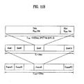
- Figure 8 illustrates a frame structure of a downlink DPCH based on the 3GPP RAN standard.
- the number of pilot bits (or symbols) in the uplink DPCH is 6 or 8 because the uplink DPCH is activated at a fixed rate of 16Kbps.
- the downlink DPCH is activated at a variable rate, it has pilot symbol patterns illustrated in Figure 9 .
- the downlink DPCH is provided with two types of channels, e.g., a dedicated physical data channel (DPDCH) and a dedicated physical control channel (DPCCH).
- DPDCH dedicated physical data channel
- DPCCH dedicated physical control channel
- the downlink DPDCH is adapted to transport the dedicated data
- the downlink DPCCH is adapted to transport the control information.
- the downlink DPCCH for transporting the control information is composed of various fields such as a pilot field 27, TPC field 26 and TFCI field 25.
- the pilot field 27 includes pilot symbols for supporting the channel estimation for coherent detection.
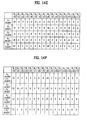
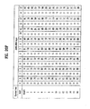
- Figure 9 is a table illustrating pilot symbol patterns contained in the downlink DPCCH, which are classified according to different symbol rates of the downlink DPCCH. For example, in the case where the symbol rate is 16, 32, 64 or 128Kbps, each slot includes four pilot symbols for an I channel branch and four pilot symbols for a Q channel branch, totaling eight pilot symbols.
- the non-shaded sequence is used for channel estimation and shaded sequences can be used as frame synchronization words.
- the remaining pilot symbols other than the frame synchronization word (e.g., channel estimation) have a value of 11.
- the symbol rate is 16, 32, 64 or 128Kbps
- the sequences, formed by pilot symbols from slot #1 to slot #16, at symbol #1 and at symbol #3 are used as the frame synchronization words. Accordingly, because the number of pilot symbols used as the frame synchronization words is 4 per slot, 64 pilot symbols are used in each radio frame.
- Figure 10 illustrates a spreading/scrambling arrangement for the downlink DPCH based on the 3GPP RAN standard.
- the arrangement of Figure 10 is provided for the spreading and scrambling of the downlink DPCH and a common control physical channel (CCPCH).
- CPCH common control physical channel
- a QPSK operation is performed with respect to a pair of symbols of the two channels in such a manner that they are serial-to-parallel converted and then mapped into I and Q channel branches, respectively.
- the I and Q channel branches are spread respectively at chip rates based on two equal channelling codes C ch .
- the spread of the two channel branches are summed and then complex-scrambled by a specific complex scrambling code C scramb .
- the complex-scrambled result is separated into real and imaginary and then transmitted, after being placed on respective carriers. Noticeably, the same scrambling code is used for all physical channels in one cell, whereas different channelizing codes are used for different physical channels.
- Data and various control information are transported to a receiver through the uplink and downlink DPCHs subjected to the above-mentioned spreading and scrambling.
- the TS S1.11 v1.1.0 specification also specified a primary common control physical channel (PCCPCH), which is a fixed rate downlink physical channel used to carry the broadcast channel (BCH), and a secondary common control physical channel (SCCPCH) used to carry the forward access channel (FACH) and the paging channel (PCH) at a constant rate.
- PCCPCH primary common control physical channel
- SCCPCH secondary common control physical channel
- FACH forward access channel
- PCH paging channel
- Figures 11A and 11B illustrate the frame structure of PCCPCH and SCCPCH, each having a pilot field.
- the TS S1.11 v1.1.0 specification recommended the pilot patterns for the PCCPCH and SCCPCH.
- the TS S1.11 v1.1.0 specification recommended the pilot pattern of the DPCH channel for the diversity antenna using open loop antenna diversity based on space time block coding based transmit diversity (STTD) and diversity antenna pilot patterns for PCCPCH and SCCPCH. Those patterns can be found in the TS S1.11 v1.1.0 specification, and detailed description is being omitted.
- STTD space time block coding based transmit diversity
- an autocorrelation function For frame synchronization, an autocorrelation function must be performed on the basis of the pilot pattern sequence. In the pilot sequence design, finding an autocorrelation of a sequence with the lowest out-of-phase coefficient is important to decrease the probability of false alarm regarding the synchronization. A false alarm is determined when a peak is detected when there should not be a peak detection.
- the result of the autocorrelation for a frame with a sequence at a prescribed pilot bit should have same maximum values at zero and middle time shifts of one correlation period, which are different in polarity, and the remaining sidelobes at time shifts other than zero and middle should have a value of zero.
- the various pilot patterns recommended in the TS S1.11 v1.1.0 do not meet this requirement, both in the uplink and downlink.
- the pilot patterns used as frame synchronization words or sequences do not achieve the optimal results. Further, the background pilot patterns do not rapidly and accurately perform the frame synchronization. Moreover, the above pilot patterns and frame synchronization sequences do not provide optimal cross-correlation and autocorrelation. Additionally, neither the TS specification nor the article provides a solution of the use of the pilot patterns for slot-by-stot double check frame synchronization scheme, and neither discloses the use of the frame synchronization sequence for channel estimation.
- An object of the present invention is to obviate at least the problems and disadvantages of the related art.
- An object of the present invention is to provide frame synchronization words resulting in optimal autocorrelation results.
- a further object of the present invention is to eliminate or prevent sidelobes.
- a further object of the present invention is to provide maximum values at zero and middle time shifts.
- Another object of the present invention is to provide a synchronization word for at least one of rapid and accurate frame synchronization.
- Another object of the present invention is to provide a slot-by-slot double check frame synchronization scheme.
- Still another object of the present invention is to provide a frame synchronization word which can be used for channel estimation.
- Still another object of the present invention is to provide good cross-correlation and autocorrelation simultaneously.
- the new, frame synchronization wards in accordance with the preferred embodiment have the lowest out-of-phase values of autocorrelation function with two peak values equal in magnitude and opposite in polarity at zero and middle shifts.
- the frame synchronization words are suitable for frame synchronization confirmation since by simply adding autocorrelation functions of such words, double maximum correlation values equal in magnittude and opposite polarity at zero and middle shifts can be achieved. This property can be used to doublecheck frame synchronization timing and reduce the synchronization search time.
- the UE establishes downlink chip synchronization and frame synchronization based on the Primary CCPCH synchronization timing and the frame offset group, slot offset group notified from the network.
- the frame synchronization can be confirmed using the frame synchronization word.
- the network establishes uplink channel chip synchronization and frame synchronization based on the frame offset group and slot offset group.
- the frame synchronization can also be confirmed using the frame synchronization word.
- Figure 12A is a table illustrating example frame synchronization words C 1 to C i-th , where each word comprises L number (L>1) of sequence of pilot bits from a prescribed bit position of the N pilot bits (N pilot >0) from each slot of L number of slots.
- the number of synchronization words i equals 8
- the number of slots L 16
- the number of pilot bits N pilot in each slot is between 4 and 16, but the example is applicable to different variations of i, L, and N pilot .
- the synchronization words C 1 -C 8 of the example can be divided into 4 classes (E-H, referred to as Preferred Correlation Sequence Pair (PCSP)) according to the autocorrelation function of the synchronization words, as follows:
- Figure 12B is a table illustrating the autocorrelation function of 1 to 16 sequences of pilot bits of each frame synchronization word classified in classes E, F, G and H within one correlation period from a time shift of 0 to 15.
- each class contains 2 sequences, and sequences of the same class have the same autocorrelation function.
- the synchronization words have the lowest out-of-phase values of autocorrelation function with two peak values equal in magnitude and opposite in polarity at zero and middle shifts.
- the results R 1 and R 2 of the autocorrelation function are complements of each other.
- R i ( ⁇ ) is the autocorrelation function of sequence C i , 1 ⁇ i ⁇ 8.
- This property allows the double-checking of the frame synchronization timing and the reduction of the synchronization search time.
- the shaded pattern of Figures 14A and 14B are used for frame synchronization (which can also be used for channel estimation), and the pilot bit other than the frame synchronization words (e.g., chancel estimation) has a value of 1.
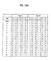
- Figure 14C is a table illustrating the mapping relationship between the 8 synchronization words C 1 -C 8 of Figure 12A and shaded pilot bit patterns of Figures 14A and 14B , where frame synchronization words C 1 , C 2 , C 3 , and C 4 are the elements of the set ⁇ E, F, G, and H ⁇ , respectively.
- N pilot 8
- the frame synchronization words at bit #1 (C 1 ), at bit #3 (C 2 ), at bit #5 (C 3 ) and at bit #7 (C 4 ) are used in the autocorrelation process for the frame synchronization.
- N pilot 5, 6, 7, and 8 in each slot, a total of four frame synchronization words are used.
- the number of pilot bits used for the frame synchronization is only 64 per frame in this example.
- the number of words used for frame synchronization can vary depending on variations of N pilot .
- N pilot 1
- one of the frame synchronization words C 1 -C 8 can be used for both frame synchronization and channel estimation due to the novel feature of this example.
- Figure 14D illustrates an example correlation circuit for frame synchronization based on pilot bits of the uplink DPCCH when frame synchronization words C 1 -C 4 are used
- the frame synchronization words C 1 -C 4 are latched us latch circuits 31-34, respectively
- Figure 14E is a table illustrating the correlation results at points A 1 -A 4 , and the summing of the correlation results at point B. As shown, the result has maximum values of opposite polarity at zero and middle time shifts R(0) and R(8). Further, the remaining sidelobes at time shifts other than zero and middle have values of zero after the addition at point B. The sidelobes are eliminated or minimized, and the results at point B correspond to the optimal results of Figure 13B .
- Figure 14F is a table illustrating various results of the addition of correlation results of points A 1 -A 4 based on the uplink pilot patterns of the example frame synchronization words C 1 -C 4 .
- the respective addition of the autocorrelation results of points (A 1 +A 2 ), (A 3 +A 4 ), (A 1 +A 4 ) and (A 2 +A 3 ) exhibit the same characteristics of the optimal results illustrated in Figure 13A .
- Figure 14G illustrates an example correlator circuit for frame synchronization based on pilot bit sequences of an uplink DPCCH.
- the elements are the same as the correlator circuit of Figure 14D .
- the frame synchronization words of (C 1 and C 2 ), (C 2 and C 3 ), (C 3 and C 4 ), or (C 4 and C 1 ) are correlated and summed to provide the results at point D
- the summation result at point D of Figure 14G is similar to the correlator circuit of Figure 14D other than the maximum values of opposite polarity being 2*L (32) and -2*L (-32), rather than 4*L (64) and -4*L (-64), respectively, corresponding tu the results of Figure 14F and optimal results of Figures 13A .
- Figure 14H illustrates the receiver circuit 60 of a base station or a user equipment to recover the received spread signal including the frame synchronization, words in the pilot field.
- the channel estimator and frame synchronizer 62 After despreading the received spread signal by the despreading circuit 61, the channel estimator and frame synchronizer 62 performs the channel estimation and the frame synchronization based on the pilot field.
- the Rake combiner 63 uses the results of the channel estimator and frame synchronizer, and after rake combining, the data is deinterleaved by the deinterleaving circuit 64 in the reverse order of the transmitter side. Thereafter, the data is recovered after decoding by a decoder 65.
- cross-correlation and autocorrelation simultaneous are difficult to achieve, where cross-correlation relates to different words at different time shifts and autocorrelation relates to same sequences which are time shifted version
- the good cross-correlation and autocorrelation of this example is based on unique properties of the frame synchronisation words.
- each word has substantially the same number of 1 and 0.
- the number (b 1 ) of pilot bits of a frame synchronization words having a value of 1 minus the number (b 0 ) of pilot bits of the frame synchronization having a value of 0 is equal to zero or close to zero.
- b 1 -b 0 when there are even number of slot numbers, there are the same number of pilot bits having a value of 1 and 0 in a single frame synchronization word such that b 1 -b 0 is zero.
- the result of b 1 -b 0 is plus or minus one, e g., close to zero.
- N pilot 5
- cross-correlation between two adjacent words used for frame synchronization is zero (orthogonal) at zero time shift.
- the cross-correlation between a word used for frame synchronization and the sequence used for channel estimation is zero (orthogonal) at all time shifts.
- there are an even number of words used for frame synchronization but all words perform channel estimation, wherein between adjacent words used for frame synchronization, there is substantially zero cross-correlation.
- the words used for frame synchronization has substantially zero cross-correlation with words not used for frame synchronization, i.e., channel estimation, at any time shifts.
- each N pilot words corresponds to a prescribed number by an autocorrelation function such that when a pair from a set of autocorrelated results corresponding to words used for frame synchronization is combed, two peak values equal in magnitude and opposite in polanty are achieved at zero and middle time shift while sidelobes are substantially eliminated at time shifts other than zero and middle.
- Autocorrelation can be generally defined as a correlation, between a word and its time shifted replica (including replica at zero time shift), where correlation is the number of bit values which are the same between two words minus the number of bit values which are different between the same two words.
- R 1 and R 2 are complements of each other.
- the shaded symbols of Figure 15A can be used for frame synchronization, and the value of pilot symbol other than for frame synchronization word, e g, channel estimation (channel estimation, word), is 11.
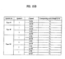
- Figure 15B illustrates the mapping relationship between the 8 frame synchronization words of Figure 12A , and shaded pilot symbol pattern of Figure 15A .
- the symbol #1 includes two frame synchronization words of C 1 (for the I channel branch I-CH, i.e., left sequence of bits from slot #1 to slot #16) and C 2 (for the Q channel branch Q-CH, i.e., right sequence of bits from slot #1 to slot #16).
- slot-by-slot double-check of the frame synchronization timing and a reduction of the frame synchronization search time can be achieved by using the autocorrelation property of the pilot symbol pattern based on equation (6).
- the characteristics described for uplink DPCCH is applicable to downlink DPCH.
- the number (b 3 ) of bit values which are the same (0,0 and 1,1) between adjacent words i.e., between synchronization word of I channel branch and synchronization word of Q channel branch of a frame synchronization symbol, or between a channel estimation word of the Q channel branch and a frame synchronization word of the I channel branch, which are adjacent, or between a frame synchronization word of the Q channel branch and a chancel estimation word of the I channel branch, which are adjacent
- the number (b 4 ) of bit values which are different (1,0 and 0,1) between adjacent words i.e., between synchronization word of I channel branch and synchronization word of Q channel branch of a frame synchronization symbol, or between a channel estimation word of the Q channel branch and a frame synchronization word of the I channel branch, which are adjacent, or
- the number of a pair of adjacent bits i.e., one bit from the Q channel branch of the symbol #0 and one bit from the I channel branch of the symbol #1, having bit values of 1,1 and 0,0 is the same as the number of adjacent bits having bit values of 1,0 and 0,1.
- b 3 -b 4 0.
- the result of b 3 -b 4 is plus or minus one, e g., a prescribed number close to zero.
- the operation and components are the same as the correlation circuit of Figure 14D for uplink DPCCH, except for the reception of I channel branch and Q channel branch synchronization words.
- the results of points A 1 -A 4 and point B is the same as Figure 14E .
- the sidelobes are eliminated or minimized, and the results correspond to the optimal results of Figure 13B . Because the number of pilot symbols (or pilot bits) used for the frame synchronization is 2 symbols per slot (or 4 bit per slot), 32 pilot symbols (or 64 pilot bits) are used in each radio frame for the frame synchronization.
- the correlator circuit of Figure 14G can be used In such a case, the I and Q channel frame synchronization words are inputted to the correlator circuit.
- the summation result would be the same as Figure 14F , which corresponds to the optimal results of Figure 13A .
- the number of pilot symbole (or pilot bits) used for the frame synchronization is 1 symbol per slot (or 2 bits per slot), and 16 symbols (or 32 pilot bits) are used in each radio frame for the frame synchronization.
- the correlation circuit of Figure 15C can be expanded to accommodate the additional frame synchronization words of the I and Q channel branches of pilot symbol #5 and symbol #7.
- the summation result would be similar to the optimal results of Figure 13B , but the maximum peak values of opposite polarity would be 128 (8*L) and -128 (-8*L).
- the number of pilot symbols (or pilot bits) used for the frame synchronization is 4 symbols per slot (or 8 bits per slot), and 64 pilot symbols (or 128 pilot bits) are used in each radio frame for the frame synchronization.
- Figure 16A illustrates pilot symbol pattern of PCCPCH.
- the shaded symbols can be used for frame synchronization, and the value of pilot symbol other than for frame synchronization is 11
- Figure 16B illustrates the mapping relationship between the synchronization words C 1 -C 8 of Figure 12A , and the shaded pilot symbol patterns of Figure 16A .
- Figure 16C illustrates pilot symbol pattern of SCCPCH.
- the shaded symbols can be used for frame synchronization, and the value of pilot symbol other than for frame synchronization is 11.
- Figure 16D illustrates the mapping relationship between the synchronization words C 1 -C 8 of Figure 12A , and the shaded pilot symbol patterns of Figure 16C .
- the frame synchronization words of PCCPCH and SCCPCH is based on the frame synchronization words C 1 -C 8 , and the disclosure for the uplink DPCCH and the downlink DPCH is applicable.
- the various characteristics including cross-correlation and autocorrelation, operations and implements are omitted since one of ordinary skill in the art can readily appreciate the example based on the uplink DPCCH and downlink DPCH.
- the non-shaded symbols are the pilot symbols not used for frame synchronization comprises symbols of 11, and the shaded symbols are used for frame synchronization.
- the frame synchronization words of the pilot pattern are used for frame synchronization confirmation, and the summation of autocorrelated values for each frame synchronization words is required.
- the property of summation of autocorrelated values of frame synchronization words is very important.
- Correlation to a prescribed frame synchronization word is optimum method for frame synchronization. Since the frame synchronization word of pilot pattern is used for frame synchronization confirmation, the following events and parameters are used to evaluate the performance of frame synchronization confirmation using the example frame synchronization words and the current pilot patterns:
- the probability of a frame synchronization confirmation is greatly affected by the probability of a false alarm since Ps is proportional to P D and (1-P FA ) 14 or (1-P FA ) 15 .
- Ps is proportional to P D and (1-P FA ) 14 or (1-P FA ) 15 .
- P FA 10 -1
- the performance of frame synchronization can be sufficiently evaluated by selecting the threshold so that the P FA is much smaller than (1-P D ).
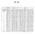
- Figure 18A The parameters of Figure 18A are used for obtaining P D , P FA , and Ps on uplink DPCCH and downlink DPCH over additive white Gaussian noise (AWGN).
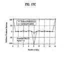
- the P D and P S of the example pilot patterns are greater than that of current pilot pattern. Furthermore, the P FA of the example pilot patterns are also smaller than that of the current pilot patterns.
- the example synchronization words are especially suitable for frame synchronization confirmation.
- double maximum values equal in magnitude and opposite polarity at zero and middle shifts are obtained. This property can be used to slot-by-slot and double-check frame synchronization timing and reduce the synchronization search time.
- the performance of frame synchronization confirmation over AWGN using pilot pattern illustrate the significant differences between the frame synchronization performance of the example pilot pattern and the current pilot pattern.
- the frame synchronization words C 1 -C 16 can be classified into the PCSP of the first example, as follows:
- FIG. 20B is a table illustrating the autocorrelation function of the pilot bits of each frame synchronization word classified in the PCSP In this particular case, each class contains four sequences and the sequences of the same class have the same autocorrelation function.
- Figures 20E and 20F illustrate the pilot symbol pattern of downlink DPCH with 8, 16, 32, 64, 128, 256, 512, 1024, 2048 and 4096 ksps
- Figure 20G illustrates a mapping relationship between the alternative frame synchronization words C 1 -C 16 of Figure 20A and the shaded frame synchronization words of Figures 20E and 20F .
- Figure 20H illustrates the pilot symbol pattern of downlink PCCPCH
- Figure 20I illustrates a mapping relationship between the alternative frame synchronization words C 1 -C 16 of Figure 20A and the shaded frame synchronization words of Figure 20H .
- this example allows a sampler construction of the correlator circuit for a receiver, thereby educing the complexity of the receiver. Due to various advantages of the examples, the first example has been accepted by the 3GPP, as shown in TS 25 211 v2 0.1, distributed June 1999, whose entire disclosure is hereby incorporated by reference therein.
- the frame synchronization words are used to design the regular pilot patterns and diversity antenna pilot patterns of uplink DPCH, and downlink DPCH and SCCPCH of the preferred embodiment.
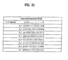
- the words C 1 -C 8 of Figure 21 are suitable for frame synchronization confirmation.
- the frame synchronization words C 1 -C 8 have the following two-valued autocorrelation function:
Abstract
Description
- The present invention relates to communication systems, and more particularly, cellular communication systems.
- The use of code division multiple access (CDMA) modulation techniques is one of several techniques for facilitating communications in which a large number of systems are present
Figure 1 generally illustrates asystem 10, which uses CDMA modulation techniques in communication between user equipment (UE) 12a and 12b, each UE including a cellular telephone, and base stations (BTS) 14a and 14b. A base station controller (BSC) 16 typically includes an interface and processing circuitry for providing system control to the BTS 14a, 14b. TheBSC 16 controls the routing of telephone calls from the public switched telephone network (PSTN) to the appropriate BTS for transmission to the appropriate UE. TheBSC 16 also controls the routing of calls from the UEs, via at least one BTS to the PSTN. TheBSC 16 may direct calls between UEs via the appropriate BTS since UEs do not typically communicate directly with one another. TheBSC 16 may be coupled to the BTS 14a and 14b by various means including dedicated telephone lines, optical fiber links or by microwave communication links. - The
arrows 13a-13d define the possible communication links between the BTS 14a and UEs 12a and 12b. Thearrows 15a-15d define the possible communication links between the BTS 14ba and UEs 12a and 12b. In the reverse channel or uplink (i.e., from UE to BTS), the UE signals is received by BTS 14a and/or BTS 14b, which, after demodulation and combining, pass the signal forward to the combining point, typically to theBSC 16. In the forward channel or downlink (i.e., from BTS to UE), the BTS signals are received by UE 12a and/or UE 12b. The above system is described inU.S. Patent Nos. 5,101,501 ;5,103,459 ;5,109,390 ; and5,416,797 , whose entire disclosure is hereby incorporated by reference therein. - A radio channel is a generally hostile medium in nature. It is rather difficult to predict its behavior. Traditionally, the radio channels are modeled in a statistical way using real propagation measurement data. In general, the signal fading in a radio environment can be decomposed into a large-scale path loss component together with a medium-scale slow varying component having a log-normal distribution, and a small-scale fast varying component with a Rician or Rayleigh distribution, depending on the presence or absence of the line-of-sight (LOS) situation between the transmitter and the receiver.
-
Figure 2 illustrates these three different propagation phenomena. An extreme variation in the transmission path between the transmitter and receiver can be found, ranging from direct LOS to severely obstructed paths due to buildings, mountains, or foliage. The phenomenon of decreasing received power with distance due to reflection, diffraction around structures, and refraction is known as path loss. - As shown, the transmitted signal is reflected by many obstacles between a transmitter and a receiver, thus creating a multipath channel. Due to the interference among many multipaths with different time delays, the received signal suffers from frequency selective multipath fading. For example, when the 2GHz carrier frequency band is used and a car having a UE is travelling at a speed of 100km/h, the maximum Doppler frequency of fading is 185Hz. While coherent detection can be used to increase link capacity, under such fast fading, the channel estimation for coherent detection is generally very difficult to achieve. Because of fading channels, it is hard to obtain a phase reference for the coherent detection of data modulated signal. Therefore, it is beneficial to have a separate pilot channel.
- Typically, a channel estimate for coherent detection is obtained from a common pilot channel. However, a common pilot channel transmitted with an omnidirectional antenna experiences a different radio channel than a traffic channel signal transmitted through a narrow beam. It has been noticed that common control channels are often problematic in the downlink when adaptive antennas are used. The problem can be circumvented by user dedicated pilot symbols, which are used as a reference signal for the channel estimation. The dedicated pilot symbols can either be time or code multiplexed.
-
Figure 3 depicts a block diagram of a transmitter and a receiver for time multiplexed pilot symbols for an improved channel estimation method that works satisfactorily under slow-to-fast fading environments. Known pilot symbols are periodically multiplexed with the sequence of the transmitted data. The pilot symbols and data symbols following pilot symbols constitute a slot, as shown inFigure 3 . - Further, in a DS-CDMA transmitter, the information signal is modulated by a spreading code, and in the receiver, it is correlated with a replica of the same code. Thus, low cross-correlation between the desired and interfering users is important to suppress the multiple access interference. Good autocorrelation properties are required for reliable initial synchronization, since large sidelobes of the autocorrelation function may lead to erroneous code synchronization decisions. Furthermore, good autocorrelation properties are important to reliably separate the multipath components.
- Since the autocorrelation function of a spreading code should resemble, as much as possible, the autocorrelation function of white Gaussian noise, the DS code sequences are also called pseudo-noise (PN) sequences. The autocorrelation and cross-correlation functions are connected in such a way that it is not possible to achieve good autocorrelation and cross-correlation values simultaneously. This can be intuitively explained by noting that having good autocorrelation properties is also an indication of good randomness of a sequence. Random codes exhibit worse cross-correlation properties than deterministic codes.
- Such mobile communication system has gone through different stages of evolution, and various countries used different standards. First generation mobile systems in the 1980s used analog transmission for speech services. Advanced Mobile Phone Service (AMPS) in the United States, Total Access Communication System (TACS) in the United Kingdom, Nordic Mobile Telephones (NMT) in Scandinavia, Nippon Telephone and Telegraph (NTT) in Japan, etc., belonged to the first generation.
- Second generation systems using digital transmission were introduced in the late 1980s. They offer higher spectrum efficiency, better data services, and more advanced roaming than the first generation systems. Global System for Mobile Communications (GSM) in Europe, Personal Digital Cellular (PDC) in Japan, and IS-95 in the United States belonged to the second generation.
- Recently, third generation mobile radio networks have been under intense research and discussion and will emerge around the year 2000. In the International Telecommunication Union (ITU), the third generation networks are called International Mobile Telecommunications - 2000 (IMT-2000) and in Europe, Universal Mobile Telecommunication System (UMTS). IMT-2000 will provide a multitude of services, including multimedia and high bit rate packet data.
- Wideband CDMA has emerged as the mainstream air interface solution for the third generation networks. Wideband CDMA systems are currently being standardized by the European Telecommunications Standards Institute (ETSI) of Europe, the Association for Radio Industry and Business (ARIB) of Japan, the TIA Engineering Committees TR45 and TR46 and the T1 committee T1P1 of the United States, and the Telecommunication Technology Association TTA I and TTA II (renamed Global CDMA I and II, respectively) in Korea. The above description and a background of various systems can be found in WIDEBAND CDMA FOR THIRD GENERATION MOBILE COMMUNICATIONS by T. Ojanpera et al, published 1998, by Artech House Publishers, whose entire disclosure is hereby incorporated by reference therein.
- Recently, ARIB in Japan, ETSI in Europe, T1 in U.S.A., and TTA in Korea have mapped out a third generation mobile communication system based on a core network and radio access technique of an existing global system for mobile communications (GSM) to provide various services including multimedia, such as audio, video and data. They have agreed to a partnership study for the presentation of a technical specification on the evolved next generation mobile communication system and named a project for the partnership study as a third generation partnership project (3GPP).
- The 3GPP is classified into three part technical studies. The first part is a 3GPP system structure and service capability based on the 3GPP specification. The second part is a study of a universal terrestrial radio access network (UTRAN), which is a radio access network (RAN) applying wideband CDMA technique based on a frequency division duplex (FDD) mode, and a TD-CDMA technique based on a time division duplex (TDD) mode. The third part is a study of a core network evolved from a second generation GSM, which has third generation networking capabilities, such as mobility management and global roaming.
- Among the technical studies of the 3GPP, the UTRAN study defines and specifies the transport and physical channels. This technical specification, TS S1.11 v1.1.0, was distributed on March of 1999, whose entire disclosure is hereby incorporated by reference therein. The physical channel includes the dedicated physical channels (DPCHs) used in the uplink and downlink. Each DPCH is generally provided with three layers, e.g., superframes, radio frames and timeslots. As specified in the 3GPP radio access network (RAN) standard, a superframe has a maximum frame unit of 720ms period. In view of the system frame numbers, one superframe is composed of seventy-two radio frames. Each radio frame has a period of 10ms, and a radio frame includes sixteen timeslots, each of which includes fields with corresponding information bits based on the DPCH.
-
Figure 4 illustrates a frame structure of an uplink DPCH based on the 3GPP RAN standard. The uplink DPCH is provided with two types of channels, e.g., a dedicated physical data channel (DPDCH) and a dedicated physical control channel (DPCCH). The uplink DPDCH is adapted to transport the dedicated data and the uplink DPCCH is adapted to transport the control information. - The uplink DPCCH for the transport of the control information includes various fields such as a
pilot field 21 of Npilot bits, a transmit power-control (TPC)field 22 of NTPC bits, a feedback information (FBI)field 23 of NFBI bits and an optional transport-combination indicator (TFCI)field 24 of NTFCI bits. Thepilot field 21 includes pilot bits Npilot for supporting channel estimation for coherent detection. TheTFCI field 4 supports the simultaneous provision of a plurality of services by the system. The absence of theTFCI field 4 in the uplink DPCCH signifies that the associated service is a fixed rate service. The parameter k determines the number of bits per uplink DPDCH/DPCCH slot. It is related to the spreading factor SF of the physical channel as SF=256/2k. The spreading factor SF may thus range from 256 down to 4. -
Figure 5 is a table showing various information of the uplink DPCCH, wherein channel bit and symbol rates are those just prior to spreading. (At the time of this technical specification, the exact number of bits of the different uplink DPCCH fields ofFigure 4 (Npilot, NTPC, NFBI, and NTFCI) was not determined.) -
Figure 6 is a table illustrating pilot bit patterns of the uplink DPCCH, and more particularly, 6-bit and 8-bit pilot bit patterns for each slot InFigure 6 , the non-shaded sequence is used for channel estimation, and shaded sequence can be used as frame synchronization words or sequences. The pilot bits other than frame synchronization word, e.g., channel estimation word, have a value of 1. - For example, in the case where each slot includes six pilot bits Npilot = 6, the sequences formed by
slot # 1 to slot #16 atbit # 1, atbit # 2, atbit # 4, and atbit # 5 are used as the frame synchronization words. In the case where each slot is composed of eight pilot bits (Npilot = 8), the sequences atbit # 1, atbit # 3, atbit # 5, and atbit # 7 are used as the frame synchronization words. In the case where the pilot bits of each sequences slot are either 6 or 8 in number, a total of four is used as the frame synchronization word. As a result, because one radio frame is provided with sixteen timeslots, the number of pilot bits used as the frame synchronization word is 64 bits per frame. -
Figure 7 shows a spreading/scrambling arrangement for the uplink DPCH based on the 3GPP RAN standard. The arrangement ofFigure 7 is provided for the execution of a quadrature phase shift keying (QPSK) operation where the uplink DPDCH and DPCCH are mapped into I and Q channel branches, respectively. - The spreading is an operation for switching all symbols through the respective channel branches to a plurality of chips. The I and Q channel branches are spread respectively at chip rates based on two different orthogonal variable spreading factors (OVSFs), or channelizing codes CD and CC. The OVSF represents the number of chips per symbol on each channel branch. The spread of two channel branches are summed and then complex-scrambled by a specific complex scrambling code Cscramb. The complex-scrambled result is separated into real and imaginary and then transmitted after being placed on respective carriers.
-
Figure 8 illustrates a frame structure of a downlink DPCH based on the 3GPP RAN standard. The number of pilot bits (or symbols) in the uplink DPCH is 6 or 8 because the uplink DPCH is activated at a fixed rate of 16Kbps. However, since the downlink DPCH is activated at a variable rate, it has pilot symbol patterns illustrated inFigure 9 . - With reference to
Figure 8 , similar to the uplink DPCH, the downlink DPCH is provided with two types of channels, e.g., a dedicated physical data channel (DPDCH) and a dedicated physical control channel (DPCCH). In the downlink DPCH, the downlink DPDCH is adapted to transport the dedicated data and the downlink DPCCH is adapted to transport the control information. The downlink DPCCH for transporting the control information is composed of various fields such as apilot field 27,TPC field 26 andTFCI field 25. Thepilot field 27 includes pilot symbols for supporting the channel estimation for coherent detection. -
Figure 9 is a table illustrating pilot symbol patterns contained in the downlink DPCCH, which are classified according to different symbol rates of the downlink DPCCH. For example, in the case where the symbol rate is 16, 32, 64 or 128Kbps, each slot includes four pilot symbols for an I channel branch and four pilot symbols for a Q channel branch, totaling eight pilot symbols. - In
Figure 9 , the non-shaded sequence is used for channel estimation and shaded sequences can be used as frame synchronization words. The remaining pilot symbols other than the frame synchronization word (e.g., channel estimation) have a value of 11. For example, in the case where the symbol rate is 16, 32, 64 or 128Kbps, the sequences, formed by pilot symbols fromslot # 1 to slot #16, atsymbol # 1 and atsymbol # 3 are used as the frame synchronization words. Accordingly, because the number of pilot symbols used as the frame synchronization words is 4 per slot, 64 pilot symbols are used in each radio frame. -
Figure 10 illustrates a spreading/scrambling arrangement for the downlink DPCH based on the 3GPP RAN standard. The arrangement ofFigure 10 is provided for the spreading and scrambling of the downlink DPCH and a common control physical channel (CCPCH). A QPSK operation is performed with respect to a pair of symbols of the two channels in such a manner that they are serial-to-parallel converted and then mapped into I and Q channel branches, respectively. - The I and Q channel branches are spread respectively at chip rates based on two equal channelling codes Cch. The spread of the two channel branches are summed and then complex-scrambled by a specific complex scrambling code Cscramb. The complex-scrambled result is separated into real and imaginary and then transmitted, after being placed on respective carriers. Noticeably, the same scrambling code is used for all physical channels in one cell, whereas different channelizing codes are used for different physical channels. Data and various control information are transported to a receiver through the uplink and downlink DPCHs subjected to the above-mentioned spreading and scrambling.
- The TS S1.11 v1.1.0 specification also specified a primary common control physical channel (PCCPCH), which is a fixed rate downlink physical channel used to carry the broadcast channel (BCH), and a secondary common control physical channel (SCCPCH) used to carry the forward access channel (FACH) and the paging channel (PCH) at a constant rate.
Figures 11A and11B illustrate the frame structure of PCCPCH and SCCPCH, each having a pilot field. The TS S1.11 v1.1.0 specification recommended the pilot patterns for the PCCPCH and SCCPCH. Further, the TS S1.11 v1.1.0 specification recommended the pilot pattern of the DPCH channel for the diversity antenna using open loop antenna diversity based on space time block coding based transmit diversity (STTD) and diversity antenna pilot patterns for PCCPCH and SCCPCH. Those patterns can be found in the TS S1.11 v1.1.0 specification, and detailed description is being omitted. - For frame synchronization, an autocorrelation function must be performed on the basis of the pilot pattern sequence. In the pilot sequence design, finding an autocorrelation of a sequence with the lowest out-of-phase coefficient is important to decrease the probability of false alarm regarding the synchronization. A false alarm is determined when a peak is detected when there should not be a peak detection.
- Optimally, the result of the autocorrelation for a frame with a sequence at a prescribed pilot bit should have same maximum values at zero and middle time shifts of one correlation period, which are different in polarity, and the remaining sidelobes at time shifts other than zero and middle should have a value of zero. However, the various pilot patterns recommended in the TS S1.11 v1.1.0 do not meet this requirement, both in the uplink and downlink.
- In an article entitled "Synchronization Sequence Design with Double Thresholds for Digital Cellular Telephone" by Young Joon Song et al. (August 18-20, 1998), the present inventor being a co-author, the article describes a correlator circuit for GSM codes where the out-of-phase coefficients are all zero except one exception at zero and middle shift having a first peak and a second peak, where the first and second peaks are opposite in polarity, but the peaks are not equal to one another. Further, the article describes lowest out-of-phase coefficients of +4 and -4. However, the article does not provide how such sequences and autocorrelation can be used to achieve the above described optimal results, and the article does not provide sufficient disclosure that the sequences achieve or can achieve the lowest autocorrelation sidelobes.
- As described above, the pilot patterns used as frame synchronization words or sequences do not achieve the optimal results. Further, the background pilot patterns do not rapidly and accurately perform the frame synchronization. Moreover, the above pilot patterns and frame synchronization sequences do not provide optimal cross-correlation and autocorrelation. Additionally, neither the TS specification nor the article provides a solution of the use of the pilot patterns for slot-by-stot double check frame synchronization scheme, and neither discloses the use of the frame synchronization sequence for channel estimation.
- "Digital Communication by Satellite",J J Spilker, 1977, Prentice Hall Ptr, and "Transport channels and physical channels (FDD)" TSG-
RAN Working Group 1Meeting # 2; TSGR1#2 (99)049Rev 1 both disclose example bit patterns for use in synchronisation. - An object of the present invention is to obviate at least the problems and disadvantages of the related art.
- An object of the present invention is to provide frame synchronization words resulting in optimal autocorrelation results.
- A further object of the present invention is to eliminate or prevent sidelobes.
- A further object of the present invention is to provide maximum values at zero and middle time shifts.
- Another object of the present invention is to provide a synchronization word for at least one of rapid and accurate frame synchronization.
- Another object of the present invention is to provide a slot-by-slot double check frame synchronization scheme.
- Still another object of the present invention is to provide a frame synchronization word which can be used for channel estimation.
- Still another object of the present invention is to provide good cross-correlation and autocorrelation simultaneously.
- According to an aspect of the invention, there is provided a device according to
claim 1. - Additional advantages, objects, and features of the invention will be set forth in part in the description which follows and in part will become apparent to those having ordinary skill in the art upon examination of the following or may be learned from practice of the invention. The objects and advantages of the invention may be realized and attained as particularly pointed out in the appended claims.
- The invention will be described in detail with reference to the following drawings in which like reference numerals refer to like elements wherein:
-
Figure 1 generally illustrates a system, which uses CDMA modulation techniques in communication between user and base stations; -
Figure 2 illustrates these three different propagation phenomena; -
Figure 3 depicts a block diagram of a transmitter and a receiver for time multiplexed pilot symbols; -
Figure 4 illustrates a frame structure of an uplink DPCH based on the 3GPP RAN standard; -
Figure 5 is a table showing various information of the uplink DPCCH, -
Figure 6 is a table illustrating pilot bit patterns of the uplink DPCCH; -
Figure 7 shows a spreading/scrambling arrangement for the uplink DPCH based on the 3GPP RAN standard; -
Figure 8 illustrates a frame structure of a downlink DPCH based on the 3GPP RAN standard; -
Figure 9 is a table illustrating pilot symbol patterns contained in the downlink DPCCH; -
Figure 10 illustrates a spreading/scrambling arrangement for the downlink DPCH based on the 3GPP RAN standard; -
Figures 11A and11B illustrate the frame structure of PCCPCH and SCCPCH, respectively; -
Figure 12A is a table illustrating example frame synchronization words Cl to Ci-th; -
Figure 12B is a table illustrating the autocorrelation function of the sequences of pilot bits; -
Figure 13A illustrates addition of two autocorrelation functions; -
Figure 13B illustrates addition of the four autocorrelation functions; -
Figures 14A and14B are tables illustrating example pilot patterns for uplink DPCCH; -
Figure 14C is a table illustrating the mapping relationship between the 8 synchronization words C1-C8 ofFigure 12A and shaded pilot bit patterns ofFigures 14A and14B ; -
Figure 14D illustrates an example, correlation circuit for frame synchronization based on pilot bits of the uplink DPCCH; -
Figure 14E is a table illustrating the correlation results at points A1-A4, and the summing of the correlation results at point B ofFigure 14D . -
Figure 14F is a table illustrating various results of the addition of correlation results based on the uplink pilot patterns of the example frame synchronization words; -
Figure 14G illustrates another example correlator circuit for frame synchronization based on pilot bit sequences of an uplink DPCCH; -
Figure 14H illustrates the receiver circuit of a base station or a user equipment to recover the received spread signal including the frame synchronization words in the pilot field; -
Figure 14I illustrates results of correlation circuit using the pilot pattern of the technical specification; -
Figure 14J illustrates a time shift graph of the summation of results ofFigure 14I ; -
Figure 15A illustrates the pilot symbol patterns for downlink DPCH; -
Figure 15B illustrates the mapping relationship between the 8 frame synchronization words ofFigure 12A , and shaded pilot symbol pattern ofFigure 15A ; -
Figure 15C illustrates another example correlation circuit for frame synchronization for downlink DPCCH; -
Figure 16A illustrates pilot symbol pattern of PCCPCH; -
Figure 16B illustrates the mapping relationship between the synchronization words C1-C8 ofFigure 12A , and the shaded pilot symbol patterns ofFigure 16A ; -
Figures 16C illustrates pilot symbol pattern of SCCHPCH; -
Figure 16D illustrates the mapping relationship between the synchronization words C1-C8 ofFigure 12A , and the shaded pilot symbol patterns ofFigure 16C ; -
Figures 17A-17C illustrate addition of autocorrelation functions of example frame synchronization word and current pilot patterns (described in TS S1.11 v1.1 0 specification) for DPCHs and PCCPCH; -
Figure 18A illustrates the parameters used for obtaining PD, PFA, and Ps on uplink DPCCH and downlink DPCH over additive white Gaussian noise (AWGN); -
Figure 18B illustrates the probability of detection PD on downlink DPCCH over AWGN channel; -
Figure 18C illustrates the probability of false alarm PFA on downlink DPCCH over AWGN channel; -
Figure 18D illustrates the probability of a frame synchronization confirmation success PS on downlink DPCCH over AWGN channel; -
Figure 19A illustrates pilot symbol patterns of downlink DPCH for the diversity antenna using a space time block coding based transmit diversity (STTD); -
Figure 19B illustrates the mapping relationship between the 8 words C1-C8 ofFigure 12A and shaded pilot symbol patterns ofFigure 19A ; -
Figure 19C illustrates the diversity antenna pilot symbol pattern for PCCPCH; -
Figure 19D illustrates the mapping relationship between the words C1-C8 ofFigure 12A and shadowed pilot symbol patterns ofFigure 19C ; -
Figure 19E illustrates the pilot symbol pattern for the diversity antenna when STTD encoding is used on the SCCPCH; -
Figure 19F illustrates the mapping relationship between the words C1-C8 ofFigure 12A and shaded pilot symbol patterns ofFigure 19E ; -
Figure 20A is a table illustrating example frame synchronization words C1-C16 (i=16) and autocorrelated function; -
Figure 20B is a table illustrating the autocorrelation function of the pilot bits of each frame synchronization word classified in the PCSP, -
Figure 20C illustrates the pilot bit pattern of uplink DPCCH; -
Figure 20D illustrates a mapping relationship between the alternative frame synchronization words C1-C16 ofFigure 20A and the shaded frame synchronization words ofFigure 20C ; -
Figures 20E and20F illustrate the pilot symbol pattern of downlink DPCH; -
Figure 20G illustrates a mapping relationship between the alternative frame synchronization words C1-C16 ofFigure 20A and the shaded frame synchronization words ofFigures 20E and20F ; -
Figure 20H illustrates the pilot symbol pattern of downlink PCCPCH; -
Figure 20I illustrates a mapping relationship between the alternative frame synchronization words C1-C16 ofFigure 20A and the shaded frame synchronization words ofFigure 20H . -
Figure 21 illustrates a preferred embodiment for the new frame synchronization words C1-Ci-th; -
Figure 22A illustrates the addition of two auto-correlation functions; -
Figure 22B illustrates the addition of two cross-correlation functions between the two frame synchronization words within the same class; -
Figure 22C illustrates the addition of four auto-correlation functions; -
Figure 22D illustrates the addition of four cross-correlation functions between the four frame synchronization words of two classes; -
Figures 23A illustrates the pilot bit patterns on uplink DPCCH with Npilot = 2, 3, and 4; -
Figure 23C illustrates the pilot bit patterns on uplink DPCCH with Npilot = 2,3, and 4 in accordance with an alternative embodiment compared toFigure 23A ; -
Figures 23E and23F illustrate the pilot bit patterns on uplink DPCCH with Npilot = 5, 6, 7, and 8; -
Figures 23B and23D illustrate the mapping relationship between the frame synchronization words ofFigure 21 , and shaded frame synchronization words ofFigures 23A and23D , respectively; -
Figure 23G illustrates the mapping relationship between the frame synchronization words ofFigure 21 , and the shaded frame synchronization words ofFigures 23E and23F ; -
Figure 23H illustrates the structure of random access channel; -
Figure 23I illustrates the random access message control fields; -
Figure 23J illustrates the pilot bit pattern of the RACH; -
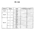
Figure 24A illustrates the pilot symbol patterns on downlink DPCH when Npilot = 2, 4, 8, and 16; -
Figure 24B illustrates the mapping relationship between the frame synchronization words C1-C8 ofFigure 21 and shaded pilot symbol patterns ofFigure 24A ; -
Figure 24C illustrates the pilot symbol patterns of downlink DPCH for the diversity antenna using STTD; -
Figure 24D illustrates the mapping relationship between the frame synchronization words C1-C8 ofFigure 21 and shaded pilot symbol patterns ofFigure 24C ; -
Figure 25A illustrates the pilot symbol patterns for downlink SCCPCH for Npilot = 8 and 16; -
Figure 25B illustrates the mapping relationship of the frame synchronization words C1-C8 ofFigure 21 and shaded pilot symbol patterns ofFigure 25A ; -
Figure 25C illustrates the pilot symbol patterns of downlink SCCPCH for Npilot = 8 and 16 for the diversity antenna using STTD; -
Figure 25D illustrates the mapping relationship between the frame synchronization words C1-C8 ofFigure 21 and shaded pilot symbol patterns ofFigure 25C ; -
Figure 26A illustrates the parameters used to evaluate the performance of the pilot bit pattern on uplink DPCCH over AWGN; -
Figure 26B illustrates the probability of frame synchronization confirmation success Ps on uplink DPCCH with Npilot =6 over AWGN channel; -
Figure 26C illustrates the probability of a false alarm PFA on uplink DPCCH with Npilot =6 over AWGN channel; and -
Figure 27 is a comparision chart between the embodiments for 15 timeslots and 16 slots. - The new, frame synchronization wards in accordance with the preferred embodiment have the lowest out-of-phase values of autocorrelation function with two peak values equal in magnitude and opposite in polarity at zero and middle shifts. The frame synchronization words are suitable for frame synchronization confirmation since by simply adding
autocorrelation functions of such words, double maximum correlation values equal in
magnittude and opposite polarity at zero and middle shifts can be achieved. This property
can be used to doublecheck frame synchronization timing and reduce the synchronization
search time. - The UE establishes downlink chip synchronization and frame synchronization based on the Primary CCPCH synchronization timing and the frame offset group, slot offset group notified from the network. The frame synchronization can be confirmed using the frame synchronization word. The network establishes uplink channel chip synchronization and frame synchronization based on the frame offset group and slot offset group. The frame synchronization can also be confirmed using the frame synchronization word.
- When long scrambling code is used on uplink channels or downlink channels, failure in frame synchronization confirmation using frame synchronization words always means losing frame and chip synchronizations since the phase of long scrambling code repeats every frame. Whereas in the case of short scrambling code on uplink DPCCH, failure in frame synchronization confirmation does not always implies losing chip synchronization since the length of short scrambling code is 256 and it corresponds to one symbol period of uplink DPCCH with SF = 256. Thus, the frame synchronization word of pilot pattern can detect synchronization status and this information can be used in RRC Connection Establishment and Release Procedures of
Layer 2. -
Figure 12A is a table illustrating example frame synchronization words C1 to Ci-th, where each word comprises L number (L>1) of sequence of pilot bits from a prescribed bit position of the Npilot bits (Npilot>0) from each slot of L number of slots. Preferably, the number of synchronization words i equals 8, the number of slots L =16 and the number of pilot bits Npilot in each slot is between 4 and 16, but the example is applicable to different variations of i, L, and Npilot. - The synchronization words C1-C8 of the example can be divided into 4 classes (E-H, referred to as Preferred Correlation Sequence Pair (PCSP)) according to the autocorrelation function of the synchronization words, as follows:
- E = {C1, C5}
- F = {C2, C6,}
- G = {C3, C7}
- H = {C4, C8}
-
Figure 12B is a table illustrating the autocorrelation function of 1 to 16 sequences of pilot bits of each frame synchronization word classified in classes E, F, G and H within one correlation period from a time shift of 0 to 15. As shown inFigures 12A and 12B , each class contains 2 sequences, and sequences of the same class have the same autocorrelation function. FromFigure 12B , the synchronization words have the lowest out-of-phase values of autocorrelation function with two peak values equal in magnitude and opposite in polarity at zero and middle shifts. Moreover, the results R1 and R2 of the autocorrelation function are complements of each other. The following relationships between the autocorrelation functions are expressed in equations (1)-(4):


- From equations (1), (2), and (3), the following equation is obtained.

- The addition of two autocorrelation functions RE (τ) and RF (τ), or RG (τ) and RH (τ) becomes the function with two peak values equal in magnitude and opposite in polarity at zero and middle shifts, and all zero values except the zero and middle shifts, which is depicted in
Figure 13A , where the peak values equal 2*L or -2*L. The peak values ofFigure 13A are 32 and -32, Since L=16. The other combinations such as (RE (τ) + RG (τ)), (RE (τ) + RH (τ)), (RF (τ) + RG (τ)), and (RF (τ) + RH (τ)) do not have the same value as inFigure 13A . By using the derived properties of the frame synchronization words, the following property is achieved.
where Ri (τ) is the autocorrelation function of sequence Ci , 1≤ i ≤ 8. - The addition of the four autocorrelation functions is illustrated in
Figure 13B , which is the same asFigure 13B except that the maximum value is doubled to 4*L or -4*L (the maximum values being 64 and -64 for this example) since (RE(τ) + RF(τ) + RG(τ) + RH(τ)) = 2 (RE(τ) + RF(τ)) by equations (5) and (6). This property allows the double-checking of the frame synchronization timing and the reduction of the synchronization search time. -
Figures 14A and14B are tables illustrating the pilot patterns in accordance with an example for uplink DPCCH with Npilot = 5, 6, 7, and 8. The shaded pattern ofFigures 14A and14B are used for frame synchronization (which can also be used for channel estimation), and the pilot bit other than the frame synchronization words (e.g., chancel estimation) has a value of 1.Figure 14C is a table illustrating the mapping relationship between the 8 synchronization words C1-C8 ofFigure 12A and shaded pilot bit patterns ofFigures 14A and14B , where frame synchronization words C1, C2, C3, and C4 are the elements of the set {E, F, G, and H}, respectively. The results ofFigures 13A and 13B are obtained by α = 1 and 2 in equation (6), respectively, which allows a double-check of the frame synchronization timing and a reduction of the synchronization time on uplink DPCCH with Npilot = 5, 6, 7, and 8. - For example, the frame synchronization words at bit #1 (C1), at bit #2 (C2), at bit #4 (C3) and at bit #5 (C4) are used in the autocorrelation process for the frame synchronization when Npilot=6. For Npilot=8, the frame synchronization words at bit #1 (C1), at bit #3 (C2), at bit #5 (C3) and at bit #7 (C4) are used in the autocorrelation process for the frame synchronization. For Npilot=5, 6, 7, and 8 in each slot, a total of four frame synchronization words are used. As a result since one radio frame has sixteen timeslots, the number of pilot bits used for the frame synchronization is only 64 per frame in this example.
As can be appreciated, the number of words used for frame synchronization can vary depending on variations of Npilot. For example, when Npilot=1, one of the frame synchronization words C1-C8 can be used for both frame synchronization and channel estimation due to the novel feature of this example. -
Figure 14D illustrates an example correlation circuit for frame synchronization based on pilot bits of the uplink DPCCH when frame synchronization words C1-C4 are used The frame synchronization words C1-C4 are latched us latch circuits 31-34, respectively The correlators 41-44 perform correlation function R(x), where x=0 to L-1, of the frame sychronization words C1-C4, respectively, to generate the correlation results A1-A4, which are stored in buffers 51-53 -
Figure 14E is a table illustrating the correlation results at points A1-A4, and the summing of the correlation results at point B. As shown, the result has maximum values of opposite polarity at zero and middle time shifts R(0) and R(8). Further, the remaining sidelobes at time shifts other than zero and middle have values of zero after the addition at point B. The sidelobes are eliminated or minimized, and the results at point B correspond to the optimal results ofFigure 13B . -
Figure 14F is a table illustrating various results of the addition of correlation results of points A1-A4 based on the uplink pilot patterns of the example frame synchronization words C1-C4. The respective addition of the autocorrelation results of points (A1+A2), (A3+A4), (A1+A4) and (A2+A3) exhibit the same characteristics of the optimal results illustrated inFigure 13A . -
Figure 14G illustrates an example correlator circuit for frame synchronization based on pilot bit sequences of an uplink DPCCH. The elements are the same as the correlator circuit ofFigure 14D . The frame synchronization words of (C1 and C2), (C2 and C3), (C3 and C4), or (C4 and C1) are correlated and summed to provide the results at point D The summation result at point D ofFigure 14G is similar to the correlator circuit ofFigure 14D other than the maximum values of opposite polarity being 2*L (32) and -2*L (-32), rather than 4*L (64) and -4*L (-64), respectively, corresponding tu the results ofFigure 14F and optimal results ofFigures 13A . -
Figure 14H illustrates thereceiver circuit 60 of a base station or a user equipment to recover the received spread signal including the frame synchronization, words in the pilot field. After despreading the received spread signal by thedespreading circuit 61, the channel estimator andframe synchronizer 62 performs the channel estimation and the frame synchronization based on the pilot field. TheRake combiner 63 uses the results of the channel estimator and frame synchronizer, and after rake combining, the data is deinterleaved by thedeinterleaving circuit 64 in the reverse order of the transmitter side. Thereafter, the data is recovered after decoding by adecoder 65. - The advantages of this example can be readily discerned based on comparison of the frame synchronization words previously recommended in TS S1.11 v.1.10 specification and the frame synchronization words for, e.g., Npilot=6. Applying the same principle of equations (1)-(6) and the correlator circuit of
Figure 14D , the results inFigure 14I are obtained for the pilot pattern indicated in the technical specification. When the summation result at point B is mapped on a time shift graph, the problem of sidelobes is readily apparent, as shown inFigure 14J . In other words, there is no maximum peak values of opposite polarity at zero and middle time shifts, and sidelobes are present at time shifts other than zero and middle. - As described in the background art, obtaining good cross-correlation and autocorrelation simultaneous is difficult to achieve, where cross-correlation relates to different words at different time shifts and autocorrelation relates to same sequences which are time shifted version The good cross-correlation and autocorrelation of this example is based on unique properties of the frame synchronisation words.
- The unique characteristics of the example frame synchronization words can be readily discerned in view of
Figures 12 ,14A and14B . As shown in frame synchronization words C1-C8 ofFigure 12 , each word has substantially the same number of 1 and 0. In other words, the number (b1) of pilot bits of a frame synchronization words having a value of 1 minus the number (b0) of pilot bits of the frame synchronization having a value of 0 is equal to zero or close to zero. Preferably, - when there are even number of slot numbers, there are the same number of pilot bits having a value of 1 and 0 in a single frame synchronization word such that b1-b0 is zero. As can be appreciated, when there are an odd number of pilot bits in a single frame synchronization word, the result of b1-b0 is plus or minus one, e g., close to zero. - The second characteristic of the frame synchronization words can be discerned by an examination between a pair of adjacent frame synchronization words (shaded patterns of
Figures 14A and14B for Npilot=5, 6, and 7), or between a pair of adjacent frame synchronization word and channel estimation word (shaded and non-shaded patterns ofFigures 14A and14B for Npilot=5, 6, 7, and 8). Generally, the number (b3) of bit values which are the same (0, 0 and 1,1) between a pair of adjacent words (i.e., between two adjacent frame synchronization words, or between a frame synchronization word and a channel estimation word, which are adjacent) minus the number (b4) of bit values which are different (1,0 or 0,1) between adjacent words (i.e, between two adjacent frame synchronization words, or between a frame synchronization word and a channel estimation word, which are adjacent) equals zero or a prescribed number close to zero. - In the example, the number (b3) of pilot bit values which are the same between two adjacent words equals the number (b4) of pilot bit value which are different between the two adjacent words, i.e., b3-b4=0. In the example, when the Npilot=5, between two synchronization words of C1 at
bit # 0 and C2 atbit # 1, there same number of pilot bit values which are the same (0,0 and 1,1) and pilot bit values which are different (1,0 and 0,1) fromslot # 1 to slot #16, as shown inFigure 14A . Similarly, between a synchronization word C2 atbit # 1 and a channel estimation word atbit # 2, there same number of pilot bit values which are the same (0,0 and 1,1) and pilot bit values which are different (1,0 and 0,1) fromslot # 1 to slot #16. The same applies between two adjacent words atbit # 2 andbit # 3, and between two adjacent words atbit # 3 andbit # 4. The above also applies to adjacent words of Npilot=6, 7 and 8. As can be appreciated, when an odd number of slots are used, the result of b3-b4 equals plus or minus one, e.g., close to zero. - As a result of such a characteristic, cross-correlation between two adjacent words used for frame synchronization is zero (orthogonal) at zero time shift. Further, the cross-correlation between a word used for frame synchronization and the sequence used for channel estimation is zero (orthogonal) at all time shifts. In other word, within Npilot number of words of L-btts, there are an even number of words used for frame synchronization, but all words perform channel estimation, wherein between adjacent words used for frame synchronization, there is substantially zero cross-correlation. Moreover, the words used for frame synchronization has substantially zero cross-correlation with words not used for frame synchronization, i.e., channel estimation, at any time shifts.
- Further, each Npilot words corresponds to a prescribed number by an autocorrelation function such that when a pair from a set of autocorrelated results corresponding to words used for frame synchronization is combed, two peak values equal in magnitude and opposite in polanty are achieved at zero and middle time shift while sidelobes are substantially eliminated at time shifts other than zero and middle. Autocorrelation can be generally defined as a correlation, between a word and its time shifted replica (including replica at zero time shift), where correlation is the number of bit values which are the same between two words minus the number of bit values which are different between the same two words. Further, as shown in
Figure 12B , R1 and R2 are complements of each other. -
Figure 15A illustrates the pilot symbol patterns for downlink DPCH for Npilot=4, 8 and 16, where two pilot bits form a symbol since the right bit is used for the I channel branch and the left bit is used for the Q channel branch. In this example, Npilot=4 can be used for 8 ksps (kilo symbols per second); Npilot=8 can be used for 16, 32, 64, and 128 ksps, and Npilot=16 can be used for 256, 512, and 1024ksps. The shaded symbols ofFigure 15A can be used for frame synchronization, and the value of pilot symbol other than for frame synchronization word, e g, channel estimation (channel estimation, word), is 11. The results ofFigure 15A is obtained by allowing α = 1 for Npilot=4, α = 2 for Npilot=8, and α = 4 for Npilot=16 in equation (6) for Downlink DPCH. -
Figure 15B illustrates the mapping relationship between the 8 frame synchronization words ofFigure 12A , and shaded pilot symbol pattern ofFigure 15A . For example, when Npilotr=4, thesymbol # 1 includes two frame synchronization words of C1 (for the I channel branch I-CH, i.e., left sequence of bits fromslot # 1 to slot #16) and C2 (for the Q channel branch Q-CH, i.e., right sequence of bits fromslot # 1 to slot #16). For Npilot=8 and Npilot=16, the correspondence of words to channels for corresponding symbols is self-explanitory inFigure 15B . Similar to the uplink DPCCH, slot-by-slot double-check of the frame synchronization timing and a reduction of the frame synchronization search time can be achieved by using the autocorrelation property of the pilot symbol pattern based on equation (6). - Because the frame synchronization words of the downlink DPCH is based on frame synchronization words of
Figure 12A , the characteristics described for uplink DPCCH is applicable to downlink DPCH. For example, the number (b3) of bit values which are the same (0,0 and 1,1) between adjacent words (i.e., between synchronization word of I channel branch and synchronization word of Q channel branch of a frame synchronization symbol, or between a channel estimation word of the Q channel branch and a frame synchronization word of the I channel branch, which are adjacent, or between a frame synchronization word of the Q channel branch and a chancel estimation word of the I channel branch, which are adjacent) minus the number (b4) of bit values which are different (1,0 and 0,1) between adjacent words (i.e., between synchronization word of I channel branch and synchronization word of Q channel branch of a frame synchronization symbol, or between a channel estimation word of the Q channel branch and a frame synchronization word of the I channel branch, which are adjacent, or between a frame synchronization word of the Q channel branch and a channel estimation word of the I channel branch, which are adjacent) equals zero or a prescribed number close to zero. - For example, for Npilot=8, between the
symbols # 0 and #1, the number of a pair of adjacent bits, i.e., one bit from the Q channel branch of thesymbol # 0 and one bit from the I channel branch of thesymbol # 1, having bit values of 1,1 and 0,0 is the same as the number of adjacent bits having bit values of 1,0 and 0,1. In other words, b3-b4=0. As can be appreciated, if the number of slots L is an odd number, the result of b3-b4 is plus or minus one, e g., a prescribed number close to zero. -
Figure 15C illustrates an example correlation circuit for frame synchronization for downlink DPCCH of Npilot=8, The operation and components are the same as the correlation circuit ofFigure 14D for uplink DPCCH, except for the reception of I channel branch and Q channel branch synchronization words. The results of points A1-A4 and point B is the same asFigure 14E . Similarly, the sidelobes are eliminated or minimized, and the results correspond to the optimal results ofFigure 13B . Because the number of pilot symbols (or pilot bits) used for the frame synchronization is 2 symbols per slot (or 4 bit per slot), 32 pilot symbols (or 64 pilot bits) are used in each radio frame for the frame synchronization. - For Npilot=4 in the downlink DPCCH, the correlator circuit of
Figure 14G can be used In such a case, the I and Q channel frame synchronization words are inputted to the correlator circuit. The summation result would be the same asFigure 14F , which corresponds to the optimal results ofFigure 13A . In this case, the number of pilot symbole (or pilot bits) used for the frame synchronization is 1 symbol per slot (or 2 bits per slot), and 16 symbols (or 32 pilot bits) are used in each radio frame for the frame synchronization. - As per Npilot=16 in the downlink DPCCH, the correlation circuit of
Figure 15C can be expanded to accommodate the additional frame synchronization words of the I and Q channel branches ofpilot symbol # 5 andsymbol # 7. The summation result would be similar to the optimal results ofFigure 13B , but the maximum peak values of opposite polarity would be 128 (8*L) and -128 (-8*L). Further, the number of pilot symbols (or pilot bits) used for the frame synchronization is 4 symbols per slot (or 8 bits per slot), and 64 pilot symbols (or 128 pilot bits) are used in each radio frame for the frame synchronization. -
Figure 16A illustrates pilot symbol pattern of PCCPCH. The shaded symbols can be used for frame synchronization, and the value of pilot symbol other than for frame synchronization is 11Figure 16B illustrates the mapping relationship between the synchronization words C1-C8 ofFigure 12A , and the shaded pilot symbol patterns ofFigure 16A . A double-check frame of the synchronization timing and the reduction of the synchronization search time can be achieved with α = 1 or 2 in equation (6) -
Figure 16C illustrates pilot symbol pattern of SCCPCH. The shaded symbols can be used for frame synchronization, and the value of pilot symbol other than for frame synchronization is 11.Figure 16D illustrates the mapping relationship between the synchronization words C1-C8 ofFigure 12A , and the shaded pilot symbol patterns ofFigure 16C . - As shown above, the frame synchronization words of PCCPCH and SCCPCH is based on the frame synchronization words C1-C8, and the disclosure for the uplink DPCCH and the downlink DPCH is applicable. Hence, a detailed description regarding the various characteristics including cross-correlation and autocorrelation, operations and implements are omitted since one of ordinary skill in the art can readily appreciate the example based on the uplink DPCCH and downlink DPCH.
- As described above, the non-shaded symbols are the pilot symbols not used for frame synchronization comprises symbols of 11, and the shaded symbols are used for frame synchronization. The frame synchronization words of the pilot pattern are used for frame synchronization confirmation, and the summation of autocorrelated values for each frame synchronization words is required. The property of summation of autocorrelated values of frame synchronization words is very important.
- The addition of autocorrelation functions of frame synchronization word of the example and current pilot patterns (described in TS S1.11 v1.1.0 specification) for DPCHs and PCCPCH are depicted in
Figures 17A (Npilot = 4),Figure 17B (Npilot =8) andFigure 17C (Npilot=16). As shown, the current pilot patterns have non-zero out-of-phase autocorrelation function with peak value at zero shift, whereas the example frame synchronization words have zero out-of-phase autocorrelation function with two peak values equal in magnitude and opposite in polarity at zero and middle time shifts (delays). - Correlation to a prescribed frame synchronization word is optimum method for frame synchronization. Since the frame synchronization word of pilot pattern is used for frame synchronization confirmation, the following events and parameters are used to evaluate the performance of frame synchronization confirmation using the example frame synchronization words and the current pilot patterns:
- H1 : The event that the correlator output exceeds the predetermined threshold when the code phase offset between the received shadowed column frame synchronization word and its corresponding receiver stored frame synchronization word is zero.
- H2 : The event that the correlator output exceeds the predetermined threshold when the code phase offset between the received shadowed column frame synchronization word and its corresponding receiver stored frame synchronization word is not zero.
- H3 : One event of H1 and no event of H2 for one frame.
- H4 : The event that the correlator output exceeds the predetermined threshold or is smaller than -1×(predetermined threshold) when the code phase offset between the received shadowed column frame synchronisation word and its corresponding receiver stored frame synchronization word is 0 or 8, respectively.
- H5 : The event that the correlator output exceeds the predetermined threshold or is smaller than -1×(predetermined threshold) when the code phase offset between the received shadowed column frame synchronization word and its corresponding receiver stored frame synchronization word is not 0 and 8.
- H6: One event of H4 and no event of H5 for one frame.
- PD : Probability of a detection.
- PFA : Probability of a false alarm.
- Ps : Probability of a frame synchronization confirmation success for one frame.
- From the above definitions, when the current pilot pattern is used for frame synchronization confirmation, the probability of a detection and a false alarm can be expressed as:


- The probability of a frame synchronization confirmation success for one frame becomes PS = Prob(H3) and it can be expressed as

- Whereas in the case of the example frame synchronization words, as has been stated, double thresholds are needed for double-check frame synchronization, and the probability of a detection and a false alarm can be expressed as


- Similarly, in the case of the example frame synchronization words, the probability of a frame confirmation success for one frame becomes Ps = Prob(H6) and is given by

- From equations (9) and (12), the probability of a frame synchronization confirmation is greatly affected by the probability of a false alarm since Ps is proportional to PD and (1-PFA)14 or (1-PFA)15. For example, assume that PFA = 10-1, then (J-PFA)14 = 0.2288 and (1-PFA)15 = 0.2059. Now let PFA = 10-3, then (1-PFA)14 = 0 9861 and (1-PFA)15 = 0.9851. The performance of frame synchronization can be sufficiently evaluated by selecting the threshold so that the PFA is much smaller than (1-PD).
- The parameters of
Figure 18A are used for obtaining PD, PFA, and Ps on uplink DPCCH and downlink DPCH over additive white Gaussian noise (AWGN).Figure 18B illustrates the probability of detection PD on downlink DPCCH with Npilot=4 over AWGN channel,Figure 18C illustrates the probability of false alarm PFA on downlink DPCCH with Npilot=4 over AWGN channel, andFigure 18D illustrates the probability of a frame synchronization confirmation success Ps on downlink DPCCH with Npilot=4 over AWGN between the example pilot pattern _ and the current pilot pattern, where PD, PFA, and Ps are given as a function of Eb/N0 ratio (Eb = energy per bit, No = noise power spectral density). - The PD and PS of the example pilot patterns are greater than that of current pilot pattern. Furthermore, the PFA of the example pilot patterns are also smaller than that of the current pilot patterns. The theoretical equations (9) and (12) are identical to simulation results of
Figure 18D . Therefore, there is significant difference between the frame synchronization performance of the example pilot patterns and that of current pilot pattern. For example, fromFigure 18D , there is 3dB gain at Ps = 0.93 by employing the example pilot patterns. - The example synchronization words are especially suitable for frame synchronization confirmation. By adding the autocorrelation functions of shaded frame synchronization words, double maximum values equal in magnitude and opposite polarity at zero and middle shifts are obtained. This property can be used to slot-by-slot and double-check frame synchronization timing and reduce the synchronization search time. The performance of frame synchronization confirmation over AWGN using pilot pattern illustrate the significant differences between the frame synchronization performance of the example pilot pattern and the current pilot pattern.
- First Example of Downlink DPCH, PCCPCH and SCCPH for STTD Diversity
- Since the above is based on words C1-C8, the previous discussion regarding the uplink DPCCH and downlink DPCH, PCCPCH and SCCPH is readily applicable. One of ordinary skill in the art can readily appreciate the features for downlink using diversity antenna based on previous disclosure, and a detailed disclosure is omitted.
- Alternative Examples for Uplink DPCCH and Downlink DPCH and PCCPCH.
Figure 20A is a table illustrating other example frame synchronization words C1-C16 (i=16) and autocorrelated function The frame synchronization words C1-C16 can be classified into the PCSP of the first example, as follows: - E = {C1, C3, C9, C11}
- F = {C2, C4, C10, C12}
- G = {C5, C7, C13, C15}
- H = {C6, C8, C14, C16}
- The classification of the alternative frame synchronization words C1-C16 are also applicable to equations (1)-(6), and have the same properties and characteristics of the first example.
Figure 20B is a table illustrating the autocorrelation function of the pilot bits of each frame synchronization word classified in the PCSP In this particular case, each class contains four sequences and the sequences of the same class have the same autocorrelation function. -
Figure 20C illustrates the pilot bit pattern of plink DPCCH with Npilot=6 and 8 andFigure 20D illustrates a mapping relationship between the alternative frame synchronization words C1-C16 ofFigure 20A and the shaded frame synchronization words ofFigure 20C .Figures 20E and20F illustrate the pilot symbol pattern of downlink DPCH with 8, 16, 32, 64, 128, 256, 512, 1024, 2048 and 4096 ksps, andFigure 20G illustrates a mapping relationship between the alternative frame synchronization words C1-C16 ofFigure 20A and the shaded frame synchronization words ofFigures 20E and20F .Figure 20H illustrates the pilot symbol pattern of downlink PCCPCH andFigure 20I illustrates a mapping relationship between the alternative frame synchronization words C1-C16 ofFigure 20A and the shaded frame synchronization words ofFigure 20H . - Since the above is based on alternative words C1-C16, which have the same features as the words C1-C8 of the first example, the previous discussion regarding the uplink DPCCH and downlink DPCH, PCCPCH and SCCPH of the first example is readily applicable. One of ordinary skill in the art can readily appreciate the features of this example based on previous disclosure, and a detailed disclosure is omitted.
The example frame synchronization words are especially suitable for frame synchronization confirmation. By adding the autocorrelation functions of shaded frame synchronization words, double maximum values equal in magnitude and opposite polarity at zero and middle shifts are obtained. This property can be used to slot-by-slot and double-check frame synchronization timing and reduce the synchronization search time. Further this example allows a sampler construction of the correlator circuit for a receiver, thereby educing the complexity of the receiver. Due to various advantages of the examples, the first example has been accepted by the 3GPP, as shown inTS 25 211 v2 0.1, distributed June 1999, whose entire disclosure is hereby incorporated by reference therein. - The above pilot patterns in accordance with preferred embodiments of the present invention have various advantages including frame synchronization confirmation. However, alternative pilot patterns are needed for 15 slots (L=15) due to OHG harmonization.
Figure 21 illustrates a preferred embodiment for the new frame synchronization words C1-Ci-th, which has the auto-correlation function of lowest out-of-phase coefficient and the lowest magnitude of cross-correlation function with minus peak value at middle shift, where i=8. The frame synchronization words are used to design the regular pilot patterns and diversity antenna pilot patterns of uplink DPCH, and downlink DPCH and SCCPCH of the preferred embodiment. By using the two correlation functions, it is possible to double check frame synchronization at zero and middle shifts. When performance evaluation of single-check and double-check frame synchronization confirmation is carried out over AWGN environment, the words C1-C8 ofFigure 21 are suitable for frame synchronization confirmation - The frame synchronization words C1-C8 have the following two-valued autocorrelation function:
- preferred embodiment, the pilot bit/symbol patterns of 15 slots have been again accepted by the 3GPP.
Claims (10)
- A communication device adapted for receiving pilot bit patterns in a mobile communication system and performing at least one of a frame synchronization and a channel estimation, the communication device comprising:means for receiving pilot bit patterns through a physical channel having a radio frame with 15 slots, each slot including pilot bits having a length NPilot, where 2≤NPilot≤16,wherein pilot bit patterns included in the 15 slots of the radio frame includes at least two of the following pilot bit patterns:C1=(100011110101100),C2=(101001101110000),C3=(110001001101011),C4=(001010000111011),C5=(111010110010001),C6=(110111000010100),
- The communication device of claim 1, wherein, when NPilot is equal to 5 or 6, the pilot bit patterns included in the 15 slots of the radio frame are as follows:
NPilot = 5 NPilot 6 Bit # 0 1 2 3 4 0 1 2 3 4 5 Slot #1 1 1 I 1 0 1 1 1 1 1 0 2 0 0 1 1 0 1 0 0 1 1 0 3 0 1 1 0 1 1 0 1 1 0 0 4 0 0 1 0 0 1 0 0 1 0 0 5 1 0 1 0 1 1 1 0 1 0 1 6 1 1 1 1 0 1 1 1 1 1 0 7 1 1 1 0 0 1 1 1 1 0 0 8 1 0 1 0 0 1 1 0 1 0 0 9 0 1 1 1 0 1 0 1 1 1 0 10 1 1 1 1 1 1 1 1 1 1 1 11 0 1 1 0 1 1 0 1 1 0 1 12 1 0 1 1 1 1 1 0 1 1 1 13 1 0 1 0 0 1 1 0 1 0 0 14 0 0 1 1 1 1 0 0 1 1 1 15 0 0 1 1 1 1 0 0 1 1 1 - The communication device of claim 1, wherein, when NPilot is equal to 7 or 8, the pilot bit patterns included in the 15 slots of the radio frame are as follows:
NPilot = 7 NPilot 8 Bit # 0 1 2 3 4 5 6 0 1 2 3 4 5 6 7 Slot #1 1 1 1 1 1 0 1 1 1 1 1 1 1 1 0 2 1 0 0 1 1 0 1 1 0 1 0 1 1 1 0 3 1 0 1 1 0 1 1 1 0 1 1 1 0 1 1 4 1 0 0 1 0 0 1 1 0 1 0 1 0 1 0 5 1 1 0 1 0 1 1 1 1 1 0 1 0 1 1 6 1 1 1 1 1 0 1 1 1 1 1 1 1 1 0 7 1 1 1 1 0 0 1 1 1 1 1 1 0 1 0 8 I 1 0 1 0 0 1 1 1 1 0 1 0 1 0 9 1 0 1 1 1 0 1 1 0 1 1 1 1 1 0 10 1 1 1 1 1 1 1 1 1 1 1 1 1 1 1 11 1 0 1 1 0 1 1 1 0 1 1 1 0 1 1 12 1 1 0 1 1 1 1 1 1 1 0 1 1 1 1 13 1 1 0 1 0 0 1 1 1 1 0 1 0 1 0 14 1 0 0 1 1 1 1 1 0 1 0 1 1 1 1 15 1 0 0 1 1 1 1 1 0 1 0 1 1 1 1 - The communication device of claim 2 or 3, wherein said physical channel is an uplink dedicated physical control channel (DPCCH).
- The communication device of claim 3, wherein said physical channel carries a random access channel (RACH) when NNPilot is equal to 8.
- The communication device of claim 1, wherein, when NPilot is equal to 2, 4, 6 or 8, the pilot bit patterns included in the 15 slots of the radio frame are as follows:
NPilot NPilot=4 NPilot=8 NPilot = 16 =2 Symbol # 0 0 1 0 1 2 3 0 1 2 3 4 5 6 7 Slot #1 11 11 11 11 11 11 10 11 11 11 10 11 11 11 10 2 00 11 00 11 00 11 10 11 00 11 10 11 11 11 00 3 01 11 01 11 01 11 01 11 01 11 01 11 10 11 00 4 00 11 00 11 00 11 00 11 00 11 00 11 01 11 10 5 10 11 10 11 10 11 01 11 10 11 01 11 11 11 11 6 11 11 11 11 11 11 10 11 11 11 10 11 01 11 01 7 11 11 11 11 11 11 00 11 11 11 00 11 10 11 11 8 10 11 10 11 10 11 00 11 10 11 00 11 10 11 00 9 01 11 01 11 01 11 10 11 01 11 10 11 00 11 11 10 11 11 11 11 11 11 11 11 11 11 11 11 00 11 11 11 01 11 01 11 01 11 01 11 01 11 01 11 11 11 10 12 10 11 10 11 10 11 11 11 10 11 11 11 00 11 10 13 10 11 10 11 10 11 00 11 10 11 00 11 01 11 01 14 00 11 00 11 00 11 11 11 00 11 11 11 00 11 00 15 00 11 00 11 00 11 11 11 00 11 11 11 10 11 01 - The communication device of claim 1, wherein, when NPilot is equal to 4. 8 or 16, the pilot bit patterns included in the 15 slots of the radio frame arc as follows:
NPilot=4 NPilot=8 NPilot=16 Symbol # 0 1 0 1 2 3 0 1 2 3 4 5 6 7 Slot #1 01 10 11 00 00 10 11 00 00 10 11 00 00 10 2 10 10 11 00 00 01 11 00 00 01 11 10 00 10 3 11 10 11 11 00 00 11 11 00 00 11 10 00 11 4 10 10 11 10 00 01 11 10 00 01 11 00 00 00 5 00 10 11 11 00 11 11 11 00 11 11 01 00 10 6 01 10 11 00 00 10 11 00 00 10 11 11 00 00 7 01 10 11 10 00 10 11 10 00 10 11 01 00 11 8 00 10 11 10 00 11 11 10 00 11 11 10 00 11 9 11 10 11 00 00 00 11 00 00 00 11 01 00 01 10 01 10 11 01 00 10 11 01 00 10 11 01 00 01 11 11 10 11 11 00 00 11 11 00 00 11 00 00 10 12 00 10 11 01 00 11 11 01 00 11 11 00 00 01 13 00 10 11 10 00 11 11 10 00 11 11 11 00 00 14 10 10 11 01 00 01 11 01 00 01 11 10 00 01 15 10 10 11 01 00 01 11 01 00 01 11 11 00 11 - The communication device of claim 7, wherein the physical channel uses space time transmit diversity (STTD) encoding.
- The communication device of any one of claims 6 to 8, wherein the physical channel is a downlink dedicated physical control channel (DPCCH)
- The communication device of claim 7, wherein the physical channel is a secondary common control physical channel (S-CCPCH) where NPilot is equal to 8 or 16.
Applications Claiming Priority (15)
| Application Number | Priority Date | Filing Date | Title |
|---|---|---|---|
| KR1019990008630A KR100294711B1 (en) | 1999-03-15 | 1999-03-15 | Frame Synchronization Method using Optimal Pilot Symbol |
| KR1019990012857A KR100320421B1 (en) | 1999-04-12 | 1999-04-12 | Frame Synchronization Confirmation Method using Optimal Pilot Symbol |
| KR1019990012856A KR100323767B1 (en) | 1999-04-12 | 1999-04-12 | Frame Synchronization Maintenance Method |
| KR1019990015722A KR100317256B1 (en) | 1999-04-30 | 1999-04-30 | Frame Synchronization Method using Optimal Pilot Symbol |
| KR1019990019506A KR20000075107A (en) | 1999-05-28 | 1999-05-28 | a cell searching method using optimal frame synchronization code |
| KR1019990019505A KR100331870B1 (en) | 1999-05-28 | 1999-05-28 | Optimal pilot pattern allocation and arrangement method |
| KR1019990019610A KR100304938B1 (en) | 1999-05-29 | 1999-05-29 | Frame Synchronization Method using Optimal Pilot Pattern |
| KR1019990023141A KR100331871B1 (en) | 1999-06-19 | 1999-06-19 | method of confirming a frame synchronization, which is used slot by slot correlation results |
| KR1019990023140A KR100308151B1 (en) | 1999-06-19 | 1999-06-19 | method of confirming a frame synchronization, at that time correlation results being sampled is used |
| KR1019990023568A KR100331872B1 (en) | 1999-06-22 | 1999-06-22 | Method of generating a pilot sequences, the sequences are used for a frame synchronization |
| KR1019990023937A KR100606673B1 (en) | 1999-06-24 | 1999-06-24 | Frame synchronization method using pilot pattern |
| KR1019990026689A KR100331874B1 (en) | 1999-07-02 | 1999-07-02 | frame synchronization method using pilot pattern of common pilot channel |
| KR1019990034212A KR100339337B1 (en) | 1999-08-18 | 1999-08-18 | Frame synchronization apparatus and method using optimal pilot pattern |
| EP20070015144 EP1850511B1 (en) | 1999-03-15 | 2000-03-15 | Pilot signals for synchronization and/or channel estimation |
| EP20000302094 EP1037407B1 (en) | 1999-03-15 | 2000-03-15 | Pilot signals for synchronisation and/or channel estimation |
Related Parent Applications (3)
| Application Number | Title | Priority Date | Filing Date |
|---|---|---|---|
| EP20070015144 Division EP1850511B1 (en) | 1999-03-15 | 2000-03-15 | Pilot signals for synchronization and/or channel estimation |
| EP20070015144 Division-Into EP1850511B1 (en) | 1999-03-15 | 2000-03-15 | Pilot signals for synchronization and/or channel estimation |
| EP20000302094 Division EP1037407B1 (en) | 1999-03-15 | 2000-03-15 | Pilot signals for synchronisation and/or channel estimation |
Publications (2)
| Publication Number | Publication Date |
|---|---|
| EP2099143A1 true EP2099143A1 (en) | 2009-09-09 |
| EP2099143B1 EP2099143B1 (en) | 2015-03-11 |
Family
ID=27584380
Family Applications (5)
| Application Number | Title | Priority Date | Filing Date |
|---|---|---|---|
| EP20090154135 Expired - Lifetime EP2099143B1 (en) | 1999-03-15 | 2000-03-15 | Emitter with pilot signal synchronisation |
| EP20000302094 Expired - Lifetime EP1037407B1 (en) | 1999-03-15 | 2000-03-15 | Pilot signals for synchronisation and/or channel estimation |
| EP20070015144 Expired - Lifetime EP1850511B1 (en) | 1999-03-15 | 2000-03-15 | Pilot signals for synchronization and/or channel estimation |
| EP20090154137 Expired - Lifetime EP2081306B1 (en) | 1999-03-15 | 2000-03-15 | Emitter with pilot signal synchronisation |
| EP20000302093 Expired - Lifetime EP1039654B1 (en) | 1999-03-15 | 2000-03-15 | Pilot signals for synchronisation and/or channel estimation |
Family Applications After (4)
| Application Number | Title | Priority Date | Filing Date |
|---|---|---|---|
| EP20000302094 Expired - Lifetime EP1037407B1 (en) | 1999-03-15 | 2000-03-15 | Pilot signals for synchronisation and/or channel estimation |
| EP20070015144 Expired - Lifetime EP1850511B1 (en) | 1999-03-15 | 2000-03-15 | Pilot signals for synchronization and/or channel estimation |
| EP20090154137 Expired - Lifetime EP2081306B1 (en) | 1999-03-15 | 2000-03-15 | Emitter with pilot signal synchronisation |
| EP20000302093 Expired - Lifetime EP1039654B1 (en) | 1999-03-15 | 2000-03-15 | Pilot signals for synchronisation and/or channel estimation |
Country Status (11)
| Country | Link |
|---|---|
| US (1) | US7616681B2 (en) |
| EP (5) | EP2099143B1 (en) |
| JP (1) | JP4318963B2 (en) |
| KR (1) | KR100294711B1 (en) |
| CN (3) | CN1161903C (en) |
| AT (2) | ATE473562T1 (en) |
| BR (1) | BRPI0001674B1 (en) |
| DE (2) | DE10012284B4 (en) |
| ES (3) | ES2415884T3 (en) |
| GB (1) | GB2350760B (en) |
| HK (1) | HK1077134A1 (en) |
Cited By (2)
| Publication number | Priority date | Publication date | Assignee | Title |
|---|---|---|---|---|
| CN104796370A (en) * | 2015-03-20 | 2015-07-22 | 中国电子科技集团公司第三研究所 | Signal synchronization method and system for underwater acoustic communication and underwater acoustic communication system |
| US10833909B2 (en) | 2016-03-31 | 2020-11-10 | Fraunhofer-Gesellschaft zur Förderung der angewandten Forschung e.V. | Optimized preamble and method for interference robust packet detection for telemetry applications |
Families Citing this family (25)
| Publication number | Priority date | Publication date | Assignee | Title |
|---|---|---|---|---|
| KR100685960B1 (en) * | 2000-02-03 | 2007-02-23 | 엘지전자 주식회사 | Frame synchronization confirmation and out-of synchronization detection method using pilot pattern |
| CN1318866C (en) * | 2001-10-16 | 2007-05-30 | 日东电工株式会社 | Method for mfg. polaroid and liquid crystal display device |
| WO2003081822A1 (en) * | 2002-03-22 | 2003-10-02 | Linkair Communications,Inc. | A coding method to create mismatched spread spectrum sequence with zero correlation window |
| KR100479864B1 (en) | 2002-11-26 | 2005-03-31 | 학교법인 중앙대학교 | Method and apparatus embodying and synchronizing downlink signal in mobile communication system and method for searching cell using the same |
| FR2859025B1 (en) * | 2003-08-22 | 2006-04-21 | Cit Alcatel | METHOD FOR VALIDATING THE DETECTION OF A CORRELATION PIC BY A POSITIONING SYSTEM RECEIVER BY SATELLITE |
| EP1542488A1 (en) * | 2003-12-12 | 2005-06-15 | Telefonaktiebolaget LM Ericsson (publ) | Method and apparatus for allocating a pilot signal adapted to the channel characteristics |
| GB0420847D0 (en) | 2004-09-20 | 2004-10-20 | Koninkl Philips Electronics Nv | A radio communication system, a radio station, and a method of transmitting data |
| CN100399726C (en) * | 2004-12-20 | 2008-07-02 | 大唐移动通信设备有限公司 | Method in use for searching sync bit in broadcast |
| CN101351017B (en) * | 2005-01-10 | 2011-03-02 | 中兴通讯股份有限公司 | Method for inserting localization time slot into wireless synthesis access network |
| EP3029846A3 (en) | 2005-05-13 | 2016-08-17 | Dspace Pty Ltd | Method and system for communicating information in a digital signal |
| AU2006246322B2 (en) * | 2005-05-13 | 2010-04-22 | Dspace Pty Ltd | Method and system for communicating information in a digital signal |
| JP4632863B2 (en) * | 2005-05-20 | 2011-02-16 | 京セラ株式会社 | Wireless communication system and wireless communication method |
| WO2007073093A2 (en) * | 2005-12-20 | 2007-06-28 | Lg Electronics Inc. | Method of generating code sequence and method of transmitting signal using the same |
| US8830983B2 (en) | 2005-12-20 | 2014-09-09 | Lg Electronics Inc. | Method of generating code sequence and method of transmitting signal using the same |
| US8259852B2 (en) * | 2006-07-19 | 2012-09-04 | Broadcom Corporation | Method and system for satellite communication |
| EP2074707B1 (en) | 2006-09-26 | 2018-08-08 | LG Electronics Inc. | A method for transmitting information using sequence. |
| CN101316115B (en) * | 2007-05-31 | 2015-02-18 | 电信科学技术研究院 | Detection method, equipment and system of pilot frequency sequence signal |
| CN101359931B (en) * | 2007-07-30 | 2012-11-21 | 鼎桥通信技术有限公司 | Transmission method of channel pilot sequence |
| US9246541B2 (en) | 2008-02-01 | 2016-01-26 | Qualcomm Incorporated | UTRAN enhancements for the support of inter-cell interference cancellation |
| CN101674101B (en) * | 2008-09-08 | 2013-06-05 | 中兴通讯股份有限公司 | Method and device for storing multipath merged data of wideband code division multiple access system |
| US20100240382A1 (en) | 2009-03-19 | 2010-09-23 | Qualcomm Incorporated | Systems, apparatus and methods for interference management in wireless networks |
| KR101696464B1 (en) * | 2009-08-28 | 2017-01-16 | 엘지전자 주식회사 | Method and apparatus for transmitting pilot in wireless communication system |
| CN107431906B (en) * | 2015-04-15 | 2020-02-21 | 华为技术有限公司 | Reference signal sending and receiving method and device |
| CN106559209B (en) * | 2015-09-21 | 2020-07-17 | 中兴通讯股份有限公司 | Frame synchronization method and device |
| CN109995689B (en) * | 2017-12-29 | 2021-08-06 | 普天信息技术有限公司 | Method, device, electronic equipment and storage medium for estimating PUCCH frequency offset |
Citations (3)
| Publication number | Priority date | Publication date | Assignee | Title |
|---|---|---|---|---|
| US5101501A (en) | 1989-11-07 | 1992-03-31 | Qualcomm Incorporated | Method and system for providing a soft handoff in communications in a cdma cellular telephone system |
| US5103459A (en) | 1990-06-25 | 1992-04-07 | Qualcomm Incorporated | System and method for generating signal waveforms in a cdma cellular telephone system |
| US5109390A (en) | 1989-11-07 | 1992-04-28 | Qualcomm Incorporated | Diversity receiver in a cdma cellular telephone system |
Family Cites Families (72)
| Publication number | Priority date | Publication date | Assignee | Title |
|---|---|---|---|---|
| US3461451A (en) * | 1967-09-22 | 1969-08-12 | Itt | Code generator to produce permutations of code mates |
| CA923603A (en) * | 1970-09-23 | 1973-03-27 | Canadian Marconi Company | Circuit for avoiding false lock |
| US4901307A (en) * | 1986-10-17 | 1990-02-13 | Qualcomm, Inc. | Spread spectrum multiple access communication system using satellite or terrestrial repeaters |
| JPH0251289A (en) * | 1988-08-15 | 1990-02-21 | Sekisui Plastics Co Ltd | Manufacture of composite piezoelectric element material by laser beams |
| JPH0332241A (en) * | 1989-06-29 | 1991-02-12 | Mitsubishi Electric Corp | Spread spectrum communication system |
| WO1992016064A1 (en) | 1989-08-07 | 1992-09-17 | Omnipoint Corporation | Asymmetric spread spectrum correlator |
| US5022047A (en) * | 1989-08-07 | 1991-06-04 | Omnipoint Data Corporation | Spread spectrum correlator |
| JP3038866B2 (en) * | 1990-10-03 | 2000-05-08 | 日本電気株式会社 | Data transmission method |
| DE4203301C1 (en) * | 1992-01-31 | 1993-01-14 | Siemens Ag, 8000 Muenchen, De | |
| CA2112221A1 (en) * | 1992-04-24 | 1993-11-11 | Haruhiro Shiino | Receiver for a digital communication system |
| JP2755067B2 (en) | 1992-09-25 | 1998-05-20 | 日本電気株式会社 | Frame synchronization circuit |
| US5581580A (en) * | 1993-05-20 | 1996-12-03 | Telefonaktiebolaget Lm Ericsson | Low complexity model based channel estimation algorithm for fading channels |
| DE4318368C1 (en) * | 1993-05-28 | 1994-07-14 | Siemens Ag | Method for obtaining a signal indicating a failure of the synchronization between a pseudo random signal sequence of a transmitter and a reference pseudo random signal sequence of a receiver |
| JP3106037B2 (en) | 1993-06-30 | 2000-11-06 | 株式会社東芝 | Handles for cooking devices and cooking dishes |
| JP3222001B2 (en) * | 1993-12-14 | 2001-10-22 | ユニデン株式会社 | Channel switching control method and cordless telephone using the same |
| JP3097443B2 (en) * | 1994-02-28 | 2000-10-10 | ケイディディ株式会社 | Unique word detection method |
| FI96154C (en) * | 1994-05-30 | 1996-05-10 | Nokia Telecommunications Oy | Method for synchronizing subscriber terminals, base station and subscriber terminal |
| US5495516A (en) | 1994-06-09 | 1996-02-27 | General Datacomm, Inc. | Diagnostic channel wakeup sequence for network managed fractional T1 or E1 digital service units |
| JP2749263B2 (en) * | 1994-07-07 | 1998-05-13 | 三洋電機株式会社 | Frame synchronous playback circuit |
| US5627863A (en) * | 1994-07-15 | 1997-05-06 | Amati Communications Corporation | Frame synchronization in multicarrier transmission systems |
| US5680414A (en) * | 1994-09-09 | 1997-10-21 | Omnipoint Corporation | Synchronization apparatus and method for spread spectrum receiver |
| JP2605648B2 (en) * | 1994-12-22 | 1997-04-30 | 日本電気株式会社 | Despreading code phase detector for SS receiver |
| WO1996021294A1 (en) * | 1995-01-05 | 1996-07-11 | Ntt Mobile Communications Network Inc. | Device and method for coherent-tracking of cdma receiver |
| EP0776106B1 (en) * | 1995-06-13 | 2004-05-26 | NTT DoCoMo, Inc. | Method for synchronizing spreading code and device for synchronizing spreading code |
| FI110645B (en) | 1995-06-30 | 2003-02-28 | Nokia Corp | Reception method and base station receiver |
| JP2914232B2 (en) | 1995-08-09 | 1999-06-28 | 日本電気株式会社 | Spread spectrum communication system |
| JP2924730B2 (en) * | 1995-09-13 | 1999-07-26 | 日本電気株式会社 | Signal reception method |
| GB2309864A (en) * | 1996-01-30 | 1997-08-06 | Sony Corp | An equalizer and modulator using a training sequence and multiple correlation with a stored copy of the sequence |
| DE19614543C1 (en) * | 1996-04-12 | 1997-08-28 | Philips Patentverwaltung | Equalizer with extended channel estimation for a receiver in a digital transmission system |
| US6005903A (en) * | 1996-07-08 | 1999-12-21 | Mendelovicz; Ephraim | Digital correlator |
| US5737326A (en) * | 1996-07-12 | 1998-04-07 | Lucent Technologies Inc. | Multi-code code division multiple access receiver |
| JP2751959B2 (en) * | 1996-07-15 | 1998-05-18 | 日本電気株式会社 | Reception timing detection circuit of CDMA receiver |
| KR0183002B1 (en) | 1996-07-16 | 1999-05-15 | 서정욱 | Method of estimating eb/no in ds/cdma with a pilot signal |
| US6404732B1 (en) * | 1996-07-30 | 2002-06-11 | Agere Systems Guardian Corp. | Digital modulation system using modified orthogonal codes to reduce autocorrelation |
| JP3681230B2 (en) * | 1996-07-30 | 2005-08-10 | 松下電器産業株式会社 | Spread spectrum communication equipment |
| SE510890C2 (en) * | 1996-08-02 | 1999-07-05 | Ericsson Telefon Ab L M | Method and device for broadband transmission |
| US6067292A (en) | 1996-08-20 | 2000-05-23 | Lucent Technologies Inc | Pilot interference cancellation for a coherent wireless code division multiple access receiver |
| US5889768A (en) * | 1996-08-30 | 1999-03-30 | Motorola, Inc. | Method of and apparatus for pilot channel acquisition |
| JP3795984B2 (en) * | 1996-12-20 | 2006-07-12 | 富士通株式会社 | Wireless receiver |
| JP3242860B2 (en) * | 1997-04-08 | 2001-12-25 | シャープ株式会社 | Correlation synchronization circuit in direct spread spectrum communication system. |
| JP3204925B2 (en) * | 1997-06-18 | 2001-09-04 | 株式会社エヌ・ティ・ティ・ドコモ | Signal receiving apparatus in CDMA communication system |
| US5991330A (en) * | 1997-06-27 | 1999-11-23 | Telefonaktiebolaget L M Ericsson (Pub1) | Mobile Station synchronization within a spread spectrum communication systems |
| US5930366A (en) * | 1997-08-29 | 1999-07-27 | Telefonaktiebolaget L M Ericsson | Synchronization to a base station and code acquisition within a spread spectrum communication system |
| DE19744428C1 (en) * | 1997-10-08 | 1999-02-25 | Texas Instruments Deutschland | Digital data signal transmission method |
| JP3441636B2 (en) * | 1997-11-21 | 2003-09-02 | 株式会社エヌ・ティ・ティ・ドコモ | Apparatus and method for determining channel estimation value, receiving apparatus, and transmission system |
| JP3308481B2 (en) * | 1998-01-09 | 2002-07-29 | 沖電気工業株式会社 | Correlation value calculation device |
| JP3967452B2 (en) * | 1998-03-13 | 2007-08-29 | 株式会社東芝 | Spread spectrum wireless transmission receiver |
| JP3411214B2 (en) * | 1998-05-22 | 2003-05-26 | 三菱電機株式会社 | Digital radio communication system reception processing method and receiver |
| US6504830B1 (en) * | 1998-06-15 | 2003-01-07 | Telefonaktiebolaget Lm Ericsson Publ | Method, apparatus, and system for fast base synchronization and sector identification |
| KR20000009140A (en) * | 1998-07-21 | 2000-02-15 | 윤종용 | Apparatus and method for initial capture and frame synchronization of spread spectrum communication system |
| US6078607A (en) * | 1998-08-10 | 2000-06-20 | Omnipont Corporation | Synchronization codes for use in communication |
| US6526091B1 (en) * | 1998-08-17 | 2003-02-25 | Telefonaktiebolaget Lm Ericsson | Communication methods and apparatus based on orthogonal hadamard-based sequences having selected correlation properties |
| US6363104B1 (en) * | 1998-10-02 | 2002-03-26 | Ericsson Inc. | Method and apparatus for interference cancellation in a rake receiver |
| US6356605B1 (en) * | 1998-10-07 | 2002-03-12 | Texas Instruments Incorporated | Frame synchronization in space time block coded transmit antenna diversity for WCDMA |
| US6424642B1 (en) * | 1998-12-31 | 2002-07-23 | Texas Instruments Incorporated | Estimation of doppler frequency through autocorrelation of pilot symbols |
| US6507602B1 (en) * | 1999-01-07 | 2003-01-14 | Ericsson, Inc. | Smoothing receiver channel estimates using spectral estimation |
| US6487252B1 (en) * | 1999-01-29 | 2002-11-26 | Motorola, Inc. | Wireless communication system and method for synchronization |
| GB9904398D0 (en) | 1999-02-25 | 1999-04-21 | Fluorescience Ltd | High throughput assay |
| US6567482B1 (en) * | 1999-03-05 | 2003-05-20 | Telefonaktiebolaget Lm Ericsson (Publ) | Method and apparatus for efficient synchronization in spread spectrum communications |
| US6804264B1 (en) * | 1999-03-15 | 2004-10-12 | Lg Information & Communications, Ltd. | Pilot signals for synchronization and/or channel estimation |
| US6891815B1 (en) * | 1999-03-15 | 2005-05-10 | Young-Joon Song | Pilot signals for synchronization and/or channel estimation |
| US6987746B1 (en) * | 1999-03-15 | 2006-01-17 | Lg Information & Communications, Ltd. | Pilot signals for synchronization and/or channel estimation |
| US6791960B1 (en) * | 1999-03-15 | 2004-09-14 | Lg Information And Communications, Ltd. | Pilot signals for synchronization and/or channel estimation |
| US7012906B1 (en) * | 1999-03-15 | 2006-03-14 | Lg Information & Communications, Ltd. | Pilot signals for synchronization and/or channel estimation |
| US7496132B2 (en) * | 1999-03-15 | 2009-02-24 | Kg Electronics Inc. | Pilot signals for synchronization and/or channel estimation |
| US6721299B1 (en) * | 1999-03-15 | 2004-04-13 | Lg Information & Communications, Ltd. | Pilot signals for synchronization and/or channel estimation |
| US7039036B1 (en) * | 1999-04-01 | 2006-05-02 | Texas Instruments Incorporated | Reduced complexity primary and secondary synchronization codes with good correlation properties for WCDMA |
| US6192040B1 (en) * | 1999-04-16 | 2001-02-20 | Motorola, Inc. | Method and apparatus for producing channel estimate of a communication channel in a CDMA communication system |
| US6661832B1 (en) * | 1999-05-11 | 2003-12-09 | Qualcomm Incorporated | System and method for providing an accurate estimation of received signal interference for use in wireless communications systems |
| US6594473B1 (en) * | 1999-05-28 | 2003-07-15 | Texas Instruments Incorporated | Wireless system with transmitter having multiple transmit antennas and combining open loop and closed loop transmit diversities |
| US6363060B1 (en) * | 1999-06-30 | 2002-03-26 | Qualcomm Incorporated | Method and apparatus for fast WCDMA acquisition |
| US6385259B1 (en) * | 1999-09-30 | 2002-05-07 | Lucent Technologies, Inc. | Composite code match filters |
-
1999
- 1999-03-15 KR KR1019990008630A patent/KR100294711B1/en active IP Right Grant
-
2000
- 2000-03-14 DE DE2000112284 patent/DE10012284B4/en not_active Expired - Fee Related
- 2000-03-14 DE DE2000112286 patent/DE10012286B4/en not_active Expired - Lifetime
- 2000-03-15 CN CNB001031066A patent/CN1161903C/en not_active Expired - Fee Related
- 2000-03-15 ES ES09154137T patent/ES2415884T3/en not_active Expired - Lifetime
- 2000-03-15 EP EP20090154135 patent/EP2099143B1/en not_active Expired - Lifetime
- 2000-03-15 CN CNB2004100491090A patent/CN100483972C/en not_active Expired - Lifetime
- 2000-03-15 GB GB0006264A patent/GB2350760B/en not_active Expired - Fee Related
- 2000-03-15 EP EP20000302094 patent/EP1037407B1/en not_active Expired - Lifetime
- 2000-03-15 EP EP20070015144 patent/EP1850511B1/en not_active Expired - Lifetime
- 2000-03-15 AT AT00302094T patent/ATE473562T1/en not_active IP Right Cessation
- 2000-03-15 AT AT00302093T patent/ATE457554T1/en not_active IP Right Cessation
- 2000-03-15 ES ES07015144.4T patent/ES2502015T3/en not_active Expired - Lifetime
- 2000-03-15 EP EP20090154137 patent/EP2081306B1/en not_active Expired - Lifetime
- 2000-03-15 ES ES00302094T patent/ES2347129T3/en not_active Expired - Lifetime
- 2000-03-15 EP EP20000302093 patent/EP1039654B1/en not_active Expired - Lifetime
- 2000-03-15 BR BRPI0001674A patent/BRPI0001674B1/en not_active IP Right Cessation
- 2000-03-15 CN CN00103104A patent/CN1124708C/en not_active Expired - Lifetime
-
2003
- 2003-06-05 JP JP2003161320A patent/JP4318963B2/en not_active Expired - Lifetime
-
2005
- 2005-10-13 HK HK05109014A patent/HK1077134A1/en not_active IP Right Cessation
-
2009
- 2009-03-05 US US12/398,344 patent/US7616681B2/en not_active Expired - Fee Related
Patent Citations (5)
| Publication number | Priority date | Publication date | Assignee | Title |
|---|---|---|---|---|
| US5101501A (en) | 1989-11-07 | 1992-03-31 | Qualcomm Incorporated | Method and system for providing a soft handoff in communications in a cdma cellular telephone system |
| US5109390A (en) | 1989-11-07 | 1992-04-28 | Qualcomm Incorporated | Diversity receiver in a cdma cellular telephone system |
| US5103459A (en) | 1990-06-25 | 1992-04-07 | Qualcomm Incorporated | System and method for generating signal waveforms in a cdma cellular telephone system |
| US5416797A (en) | 1990-06-25 | 1995-05-16 | Qualcomm Incorporated | System and method for generating signal waveforms in a CDMA cellular telephone system |
| US5103459B1 (en) | 1990-06-25 | 1999-07-06 | Qualcomm Inc | System and method for generating signal waveforms in a cdma cellular telephone system |
Non-Patent Citations (3)
| Title |
|---|
| ANDREAS WILDE, SHIGENORI KINJO: "Transport channels and physical channels (FDD)", TSG-RAN WORKING GROUP1 MEETING 2, 22 February 1999 (1999-02-22) - 25 February 1999 (1999-02-25), Yokohama, Japan, pages 1 - 28, XP002450244 * |
| J.J. SPILKER, JR: "Digital Communication by Satellite", 1977, PRENTICE HALL PTR, PPER SADDLE RIVER, NJ, USA, ISBN: 0-13-214155-8, XP002239986 * |
| SONG Y S ET AL: "Synchronization sequence design with double thresholds for digital cellular telephone", 19980101, 1 January 1998 (1998-01-01), pages 314 - 317, XP007903249 * |
Cited By (4)
| Publication number | Priority date | Publication date | Assignee | Title |
|---|---|---|---|---|
| CN104796370A (en) * | 2015-03-20 | 2015-07-22 | 中国电子科技集团公司第三研究所 | Signal synchronization method and system for underwater acoustic communication and underwater acoustic communication system |
| CN104796370B (en) * | 2015-03-20 | 2018-03-30 | 中国电子科技集团公司第三研究所 | A kind of signal synchronizing method of underwater sound communication, system and underwater sound communication system |
| US10833909B2 (en) | 2016-03-31 | 2020-11-10 | Fraunhofer-Gesellschaft zur Förderung der angewandten Forschung e.V. | Optimized preamble and method for interference robust packet detection for telemetry applications |
| US10887147B2 (en) | 2016-03-31 | 2021-01-05 | Fraunhofer-Gesellschaft zur Förderung der angewandten Forschung e.V. | Optimized preamble and method for interference robust packet detection for telemetry applications |
Also Published As
Similar Documents
| Publication | Publication Date | Title |
|---|---|---|
| US6721299B1 (en) | Pilot signals for synchronization and/or channel estimation | |
| EP2081306B1 (en) | Emitter with pilot signal synchronisation | |
| US6987746B1 (en) | Pilot signals for synchronization and/or channel estimation | |
| US7602841B2 (en) | Pilot signals for synchronization and/or channel estimation | |
| US6791960B1 (en) | Pilot signals for synchronization and/or channel estimation | |
| US6891815B1 (en) | Pilot signals for synchronization and/or channel estimation | |
| US6804264B1 (en) | Pilot signals for synchronization and/or channel estimation | |
| US6078607A (en) | Synchronization codes for use in communication | |
| CA2312772A1 (en) | Method and apparatus for coherently-averaged power estimation | |
| US7012906B1 (en) | Pilot signals for synchronization and/or channel estimation | |
| Adachi et al. | Wideband wireless access based on DS-CDMA | |
| US7848393B2 (en) | Pilot signals for synchronization and/or channel estimation | |
| US7450556B2 (en) | Method and apparatus estimating cell interference and noise for CDMA packet data channels | |
| WO2002009304A1 (en) | Interference estimation in a communications system | |
| JP3463015B2 (en) | Pilot signal that can confirm synchronization in mobile communication system | |
| DaSilva et al. | Performance of the forward link of a CDMA cellular network | |
| Zhang et al. | Delay spread effects on BER performance of single code and multi-code WCDMA signalling schemes for high rate data transmission | |
| Song | Frame synchronization confirmation technique using pilot pattern | |
| KR20010054456A (en) | channel estimation method, and apparatus for the same | |
| SATO et al. | Parallel combinatorial delayed multiplexing CDMA system |
Legal Events
| Date | Code | Title | Description |
|---|---|---|---|
| PUAI | Public reference made under article 153(3) epc to a published international application that has entered the european phase |
Free format text: ORIGINAL CODE: 0009012 |
|
| 17P | Request for examination filed |
Effective date: 20090302 |
|
| AC | Divisional application: reference to earlier application |
Ref document number: 1850511 Country of ref document: EP Kind code of ref document: P Ref document number: 1037407 Country of ref document: EP Kind code of ref document: P |
|
| AK | Designated contracting states |
Kind code of ref document: A1 Designated state(s): AT BE CH CY DE DK ES FI FR GB GR IE IT LI LU MC NL PT SE |
|
| AX | Request for extension of the european patent |
Extension state: AL LT LV MK RO SI |
|
| 17Q | First examination report despatched |
Effective date: 20091117 |
|
| AKX | Designation fees paid |
Designated state(s): AT BE CH CY DE DK ES FI FR GB GR IE IT LI LU MC NL PT SE |
|
| RAP1 | Party data changed (applicant data changed or rights of an application transferred) |
Owner name: LG ELECTRONICS INC. |
|
| REG | Reference to a national code |
Ref country code: DE Ref legal event code: R079 Ref document number: 60048892 Country of ref document: DE Free format text: PREVIOUS MAIN CLASS: H04B0007260000 Ipc: H04J0013000000 |
|
| GRAP | Despatch of communication of intention to grant a patent |
Free format text: ORIGINAL CODE: EPIDOSNIGR1 |
|
| RIC1 | Information provided on ipc code assigned before grant |
Ipc: H04J 13/00 20110101AFI20140909BHEP |
|
| INTG | Intention to grant announced |
Effective date: 20141010 |
|
| GRAS | Grant fee paid |
Free format text: ORIGINAL CODE: EPIDOSNIGR3 |
|
| GRAA | (expected) grant |
Free format text: ORIGINAL CODE: 0009210 |
|
| AC | Divisional application: reference to earlier application |
Ref document number: 1850511 Country of ref document: EP Kind code of ref document: P Ref document number: 1037407 Country of ref document: EP Kind code of ref document: P |
|
| AK | Designated contracting states |
Kind code of ref document: B1 Designated state(s): AT BE CH CY DE DK ES FI FR GB GR IE IT LI LU MC NL PT SE |
|
| REG | Reference to a national code |
Ref country code: GB Ref legal event code: FG4D |
|
| REG | Reference to a national code |
Ref country code: CH Ref legal event code: EP |
|
| REG | Reference to a national code |
Ref country code: IE Ref legal event code: FG4D |
|
| REG | Reference to a national code |
Ref country code: AT Ref legal event code: REF Ref document number: 715821 Country of ref document: AT Kind code of ref document: T Effective date: 20150415 |
|
| REG | Reference to a national code |
Ref country code: DE Ref legal event code: R096 Ref document number: 60048892 Country of ref document: DE Effective date: 20150423 |
|
| REG | Reference to a national code |
Ref country code: NL Ref legal event code: VDEP Effective date: 20150311 |
|
| REG | Reference to a national code |
Ref country code: NL Ref legal event code: VDEP Effective date: 20150311 |
|
| PG25 | Lapsed in a contracting state [announced via postgrant information from national office to epo] |
Ref country code: FI Free format text: LAPSE BECAUSE OF FAILURE TO SUBMIT A TRANSLATION OF THE DESCRIPTION OR TO PAY THE FEE WITHIN THE PRESCRIBED TIME-LIMIT Effective date: 20150311 Ref country code: ES Free format text: LAPSE BECAUSE OF FAILURE TO SUBMIT A TRANSLATION OF THE DESCRIPTION OR TO PAY THE FEE WITHIN THE PRESCRIBED TIME-LIMIT Effective date: 20150311 Ref country code: SE Free format text: LAPSE BECAUSE OF FAILURE TO SUBMIT A TRANSLATION OF THE DESCRIPTION OR TO PAY THE FEE WITHIN THE PRESCRIBED TIME-LIMIT Effective date: 20150311 |
|
| REG | Reference to a national code |
Ref country code: AT Ref legal event code: MK05 Ref document number: 715821 Country of ref document: AT Kind code of ref document: T Effective date: 20150311 |
|
| PG25 | Lapsed in a contracting state [announced via postgrant information from national office to epo] |
Ref country code: GR Free format text: LAPSE BECAUSE OF FAILURE TO SUBMIT A TRANSLATION OF THE DESCRIPTION OR TO PAY THE FEE WITHIN THE PRESCRIBED TIME-LIMIT Effective date: 20150612 |
|
| PG25 | Lapsed in a contracting state [announced via postgrant information from national office to epo] |
Ref country code: NL Free format text: LAPSE BECAUSE OF FAILURE TO SUBMIT A TRANSLATION OF THE DESCRIPTION OR TO PAY THE FEE WITHIN THE PRESCRIBED TIME-LIMIT Effective date: 20150311 |
|
| PG25 | Lapsed in a contracting state [announced via postgrant information from national office to epo] |
Ref country code: PT Free format text: LAPSE BECAUSE OF FAILURE TO SUBMIT A TRANSLATION OF THE DESCRIPTION OR TO PAY THE FEE WITHIN THE PRESCRIBED TIME-LIMIT Effective date: 20150713 |
|
| REG | Reference to a national code |
Ref country code: CH Ref legal event code: PL |
|
| PG25 | Lapsed in a contracting state [announced via postgrant information from national office to epo] |
Ref country code: AT Free format text: LAPSE BECAUSE OF FAILURE TO SUBMIT A TRANSLATION OF THE DESCRIPTION OR TO PAY THE FEE WITHIN THE PRESCRIBED TIME-LIMIT Effective date: 20150311 |
|
| REG | Reference to a national code |
Ref country code: DE Ref legal event code: R097 Ref document number: 60048892 Country of ref document: DE |
|
| PG25 | Lapsed in a contracting state [announced via postgrant information from national office to epo] |
Ref country code: IT Free format text: LAPSE BECAUSE OF FAILURE TO SUBMIT A TRANSLATION OF THE DESCRIPTION OR TO PAY THE FEE WITHIN THE PRESCRIBED TIME-LIMIT Effective date: 20150311 |
|
| REG | Reference to a national code |
Ref country code: IE Ref legal event code: MM4A |
|
| PLBE | No opposition filed within time limit |
Free format text: ORIGINAL CODE: 0009261 |
|
| STAA | Information on the status of an ep patent application or granted ep patent |
Free format text: STATUS: NO OPPOSITION FILED WITHIN TIME LIMIT |
|
| PG25 | Lapsed in a contracting state [announced via postgrant information from national office to epo] |
Ref country code: DK Free format text: LAPSE BECAUSE OF FAILURE TO SUBMIT A TRANSLATION OF THE DESCRIPTION OR TO PAY THE FEE WITHIN THE PRESCRIBED TIME-LIMIT Effective date: 20150311 Ref country code: CH Free format text: LAPSE BECAUSE OF NON-PAYMENT OF DUE FEES Effective date: 20150331 Ref country code: IE Free format text: LAPSE BECAUSE OF NON-PAYMENT OF DUE FEES Effective date: 20150315 Ref country code: LI Free format text: LAPSE BECAUSE OF NON-PAYMENT OF DUE FEES Effective date: 20150331 Ref country code: MC Free format text: LAPSE BECAUSE OF FAILURE TO SUBMIT A TRANSLATION OF THE DESCRIPTION OR TO PAY THE FEE WITHIN THE PRESCRIBED TIME-LIMIT Effective date: 20150311 |
|
| 26N | No opposition filed |
Effective date: 20151214 |
|
| REG | Reference to a national code |
Ref country code: FR Ref legal event code: PLFP Year of fee payment: 17 |
|
| PG25 | Lapsed in a contracting state [announced via postgrant information from national office to epo] |
Ref country code: BE Free format text: LAPSE BECAUSE OF FAILURE TO SUBMIT A TRANSLATION OF THE DESCRIPTION OR TO PAY THE FEE WITHIN THE PRESCRIBED TIME-LIMIT Effective date: 20150311 |
|
| REG | Reference to a national code |
Ref country code: FR Ref legal event code: PLFP Year of fee payment: 18 |
|
| PG25 | Lapsed in a contracting state [announced via postgrant information from national office to epo] |
Ref country code: CY Free format text: LAPSE BECAUSE OF FAILURE TO SUBMIT A TRANSLATION OF THE DESCRIPTION OR TO PAY THE FEE WITHIN THE PRESCRIBED TIME-LIMIT Effective date: 20150311 |
|
| PG25 | Lapsed in a contracting state [announced via postgrant information from national office to epo] |
Ref country code: LU Free format text: LAPSE BECAUSE OF NON-PAYMENT OF DUE FEES Effective date: 20150315 |
|
| REG | Reference to a national code |
Ref country code: FR Ref legal event code: PLFP Year of fee payment: 19 |
|
| PGFP | Annual fee paid to national office [announced via postgrant information from national office to epo] |
Ref country code: DE Payment date: 20190207 Year of fee payment: 20 Ref country code: GB Payment date: 20190208 Year of fee payment: 20 |
|
| PGFP | Annual fee paid to national office [announced via postgrant information from national office to epo] |
Ref country code: FR Payment date: 20190211 Year of fee payment: 20 |
|
| REG | Reference to a national code |
Ref country code: DE Ref legal event code: R081 Ref document number: 60048892 Country of ref document: DE Owner name: 3G LICENSING S.A., LU Free format text: FORMER OWNER: LG ELECTRONICS INC., SEOUL, KR |
|
| REG | Reference to a national code |
Ref country code: DE Ref legal event code: R071 Ref document number: 60048892 Country of ref document: DE |
|
| REG | Reference to a national code |
Ref country code: GB Ref legal event code: PE20 Expiry date: 20200314 |
|
| PG25 | Lapsed in a contracting state [announced via postgrant information from national office to epo] |
Ref country code: GB Free format text: LAPSE BECAUSE OF EXPIRATION OF PROTECTION Effective date: 20200314 |
|
| REG | Reference to a national code |
Ref country code: GB Ref legal event code: 732E Free format text: REGISTERED BETWEEN 20200430 AND 20200506 |