EP2099033A1 - Pressure-accumulating water-charging tank - Google Patents
Pressure-accumulating water-charging tank Download PDFInfo
- Publication number
- EP2099033A1 EP2099033A1 EP07831797A EP07831797A EP2099033A1 EP 2099033 A1 EP2099033 A1 EP 2099033A1 EP 07831797 A EP07831797 A EP 07831797A EP 07831797 A EP07831797 A EP 07831797A EP 2099033 A1 EP2099033 A1 EP 2099033A1
- Authority
- EP
- European Patent Office
- Prior art keywords
- flow pipe
- jet
- vortex chamber
- small flow
- accumulator
- Prior art date
- Legal status (The legal status is an assumption and is not a legal conclusion. Google has not performed a legal analysis and makes no representation as to the accuracy of the status listed.)
- Granted
Links
Images



Classifications
-
- G—PHYSICS
- G21—NUCLEAR PHYSICS; NUCLEAR ENGINEERING
- G21C—NUCLEAR REACTORS
- G21C15/00—Cooling arrangements within the pressure vessel containing the core; Selection of specific coolants
- G21C15/18—Emergency cooling arrangements; Removing shut-down heat
-
- F—MECHANICAL ENGINEERING; LIGHTING; HEATING; WEAPONS; BLASTING
- F15—FLUID-PRESSURE ACTUATORS; HYDRAULICS OR PNEUMATICS IN GENERAL
- F15B—SYSTEMS ACTING BY MEANS OF FLUIDS IN GENERAL; FLUID-PRESSURE ACTUATORS, e.g. SERVOMOTORS; DETAILS OF FLUID-PRESSURE SYSTEMS, NOT OTHERWISE PROVIDED FOR
- F15B1/00—Installations or systems with accumulators; Supply reservoir or sump assemblies
- F15B1/26—Supply reservoir or sump assemblies
-
- F—MECHANICAL ENGINEERING; LIGHTING; HEATING; WEAPONS; BLASTING
- F15—FLUID-PRESSURE ACTUATORS; HYDRAULICS OR PNEUMATICS IN GENERAL
- F15D—FLUID DYNAMICS, i.e. METHODS OR MEANS FOR INFLUENCING THE FLOW OF GASES OR LIQUIDS
- F15D1/00—Influencing flow of fluids
- F15D1/0015—Whirl chambers, e.g. vortex valves
-
- Y—GENERAL TAGGING OF NEW TECHNOLOGICAL DEVELOPMENTS; GENERAL TAGGING OF CROSS-SECTIONAL TECHNOLOGIES SPANNING OVER SEVERAL SECTIONS OF THE IPC; TECHNICAL SUBJECTS COVERED BY FORMER USPC CROSS-REFERENCE ART COLLECTIONS [XRACs] AND DIGESTS
- Y02—TECHNOLOGIES OR APPLICATIONS FOR MITIGATION OR ADAPTATION AGAINST CLIMATE CHANGE
- Y02E—REDUCTION OF GREENHOUSE GAS [GHG] EMISSIONS, RELATED TO ENERGY GENERATION, TRANSMISSION OR DISTRIBUTION
- Y02E30/00—Energy generation of nuclear origin
- Y02E30/30—Nuclear fission reactors
-
- Y—GENERAL TAGGING OF NEW TECHNOLOGICAL DEVELOPMENTS; GENERAL TAGGING OF CROSS-SECTIONAL TECHNOLOGIES SPANNING OVER SEVERAL SECTIONS OF THE IPC; TECHNICAL SUBJECTS COVERED BY FORMER USPC CROSS-REFERENCE ART COLLECTIONS [XRACs] AND DIGESTS
- Y10—TECHNICAL SUBJECTS COVERED BY FORMER USPC
- Y10T—TECHNICAL SUBJECTS COVERED BY FORMER US CLASSIFICATION
- Y10T137/00—Fluid handling
- Y10T137/206—Flow affected by fluid contact, energy field or coanda effect [e.g., pure fluid device or system]
- Y10T137/2087—Means to cause rotational flow of fluid [e.g., vortex generator]
- Y10T137/2109—By tangential input to axial output [e.g., vortex amplifier]
- Y10T137/2115—With means to vary input or output of device
-
- Y—GENERAL TAGGING OF NEW TECHNOLOGICAL DEVELOPMENTS; GENERAL TAGGING OF CROSS-SECTIONAL TECHNOLOGIES SPANNING OVER SEVERAL SECTIONS OF THE IPC; TECHNICAL SUBJECTS COVERED BY FORMER USPC CROSS-REFERENCE ART COLLECTIONS [XRACs] AND DIGESTS
- Y10—TECHNICAL SUBJECTS COVERED BY FORMER USPC
- Y10T—TECHNICAL SUBJECTS COVERED BY FORMER US CLASSIFICATION
- Y10T137/00—Fluid handling
- Y10T137/206—Flow affected by fluid contact, energy field or coanda effect [e.g., pure fluid device or system]
- Y10T137/2164—Plural power inputs to single device
- Y10T137/2169—Intersecting at interaction region [e.g., comparator]
-
- Y—GENERAL TAGGING OF NEW TECHNOLOGICAL DEVELOPMENTS; GENERAL TAGGING OF CROSS-SECTIONAL TECHNOLOGIES SPANNING OVER SEVERAL SECTIONS OF THE IPC; TECHNICAL SUBJECTS COVERED BY FORMER USPC CROSS-REFERENCE ART COLLECTIONS [XRACs] AND DIGESTS
- Y10—TECHNICAL SUBJECTS COVERED BY FORMER USPC
- Y10T—TECHNICAL SUBJECTS COVERED BY FORMER US CLASSIFICATION
- Y10T137/00—Fluid handling
- Y10T137/206—Flow affected by fluid contact, energy field or coanda effect [e.g., pure fluid device or system]
- Y10T137/2224—Structure of body of device
Definitions
- the present invention relates to an accumulator incorporating a flow damper which is capable of statically switching flow rates from large to small.
- An emergency core cooling system is installed in a pressurized water reactor (PWR) power plant.
- the emergency core cooling system includes an accumulator and so forth on the assumption that the PWR might cause a loss of primary coolant accident.
- Water (coolant) is stored in the accumulator, and the water stored therein is pressurized by a pressurizing gas (nitrogen gas) which is filled in an upper part in the accumulator.
- a flow damper is provided in the accumulator.
- the flow damper can switch a water injection flow rate in a reactor from a large flow to a small flow statically (without moving any part thereof).
- the flow damper includes a vortex chamber, a large flow pipe, a small flow pipe, an outlet pipe and the like, and is disposed at the bottom in the accumulator (see Fig. 1 ).
- a tip end of the outlet pipe is connected to a low temperature pipeline of a reactor primary coolant loop with a check valve interposed in between. The check valve is used for avoiding a back flow from a rector primary cooling system to the accumulator.
- the amount of the coolant in a reactor vessel may be reduced, and thereby a reactor core may become exposed.
- a pressure of the primary cooling system drops below a pressure in the accumulator, the water stored in the accumulator is injected from the primary cooling system pipeline into the reactor vessel through the check valve, and thereby refloods the reactor core.
- the reactor vessel is refilled quickly by injecting water at a large flow rate at an initial stage thereof. Then, it is necessary to switch the water injection flow rate from the large flow to a small flow at a later stage when the reactor core is reflooded, because excessively injected water may spill out of the crack. In order to ensure this water injection flow rate switching operation, a reliable flow damper without a moving part is used for the accumulator.
- a flow damper 10 has a structure in which a large flow pipe 2 and a small flow pipe 3 are connected to a peripheral portion (a circumferential portion) of a cylindrical vortex chamber 1, while an outlet 4 is formed in the center of the vortex chamber 1.
- the large flow pipe 2 and the small flow pipe 3 extend in mutually different directions from the outlet 4.
- the small flow pipe 3 extends in the left direction along a tangential direction to the peripheral portion (the circumferential portion) of the vortex chamber 1.
- the large flow pipe 2 extends in the right direction while forming a predetermined angle ⁇ with the small flow pipe 3.
- an inlet of the small flow pipe 3 is located at the same level as the vortex chamber 1.
- the large flow pipe 2 is connected to a standpipe which extends upward.
- An inlet of this standpipe is located higher than the vortex chamber 1 and the inlet of the small flow pipe 3.
- an outlet pipe is connected to the outlet 4 of the vortex chamber 1.
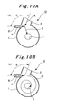
- the water in the accumulator flows into the vortex chamber 1 from both of the large flow pipe 2 and the small flow pipe 3 as indicated with arrows A and B in Fig. 10A .
- the injected water (a jet) from the large flow pipe 2 collides with the injected water (a jet) from the small flow pipe 3, and angular momenta of the jets are offset.
- the water flows directly toward the outlet 4 as indicated with an arrow C in Fig. 10A .
- no vortex is formed in the vortex chamber at this time. Accordingly, a flow resistance is reduced at this time, and thus a large amount of water flows out of the outlet 4 and is injected into the reactor vessel.
- the accumulator currently in development is the advanced accumulator which is capable of switching from a large flow to a small flow statically and securely by including the flow damper 10.
- the flow damper 10 of this advanced accumulator is required to define a proportion between the large flow and the small flow as high as possible in order to achieve a reasonable tank volume. For this reason, it is essential not to form a vortex in the vortex chamber by surely offsetting the angular momenta between the jet from the large flow pipe 2 and the jet from the small flow pipe 3 at the time of the large flow injection.
- an object of the present invention to provide an accumulator including a flow damper which is capable of suppressing formation of a vortex in a vortex chamber at the time of a large flow injection without requiring huge labors and fabrication costs.
- an accumulator is an accumulator provided with a flow damper inside, the flow damper including a cylindrical vortex chamber, a small flow pipe connected to a peripheral portion of the vortex chamber along a tangential direction thereto, a large flow pipe connected to the peripheral portion while forming a predetermined angle with the small flow pipe, and an outlet pipe connected to an outlet formed at a central part of the vortex chamber.
- the accumulator is characterized in that the flow damper includes a colliding jet controller for controlling a colliding jet composed of a jet from the large flow pipe and a jet from the small flow pipe flowing into the vortex chamber at the time of a large flow injection so that the colliding jet may proceed directly to the outlet without forming a vortex in the vortex chamber, the colliding jet controller being provided at a junction of the small flow pipe and the vortex chamber.
- an accumulator according to a second aspect of the present invention in the case of the accumulator of the first aspect, is characterized in that the colliding jet controller is a bevel formed at the junction of the small flow pipe and the vortex chamber.
- an accumulator according to a third aspect of the present invention in the case of the accumulator of the first aspect, is characterized in that the colliding jet controller is a projection formed at the junction of the small flow pipe and the vortex chamber.
- the accumulator of the first aspect of the present invention is characterized in that the flow damper includes a colliding jet controller for controlling a colliding jet composed of a jet from the large flow pipe and a jet from the small flow pipe flowing into the vortex chamber at the time of a large flow injection so that the colliding jet may proceed directly to the outlet without forming a vortex in the vortex chamber, the colliding jet controller being provided at a junction of the small flow pipe and the vortex chamber.
- either the bevel or the projection is formed as the colliding jet controller, and the colliding jet is controlled by use of the bevel or the projection.
- 21 accumulator; 22: water; 22a: water level; 23: pressurizing gas (nitrogen gas); 24: flow damper; 25: vortex chamber; 25a: inner peripheral surface; 25a-1: flat surface portion (extended surface portion); 25b: upper surface; 25c: lower surface; 26: large flow pipe; 26a: horizontal portion of large flow pipe; 26b: standpipe; 26c: inlet; 26d,26e,26f, and 26g: inner surface; 27: small flow pipe; 27a: inlet; 27b,27c,27d, and 27e: inner surface; 28: outlet pipe; 29: outlet; 30 and 31: Anti-vortex plate; 32,33, and 34: junction; 41: bevel; 51: projection
- Fig. 1 is a cross-sectional view of an accumulator according to an embodiment of the present invention.
- Fig. 2 is an enlarged cross-sectional view extracting and showing a flow damper included in the accumulator.
- Fig. 3 is a plan view of the flow damper.
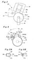
- Fig. 4 is a cross-sectional view taken along, and indicated by, the H-H arrow line in Fig. 2 .
- Fig. 5A is a cross-sectional view taken along, and indicated by, the I-I line in Fig. 4.
- Fig. 5B is a cross-sectional view taken along, and indicated by, the J-J line in Fig. 4 .
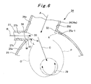
- Fig. 6 is an enlarged cross-sectional view of a substantial part in Fig. 4 .
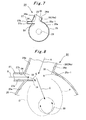
- Fig. 7 is a cross-sectional view (a cross-sectional view corresponding to Fig. 4 ) showing another configuration example of the colliding jet controller.
- Fig. 8 is an enlarged cross-sectional view (a cross-sectional view corresponding to Fig. 6 ) of a substantial part of the colliding jet controller illustrated in Fig. 7 .
- Figs. 9A and 9B are views for explaining water injection flow switching by use of the flow damper.
- An accumulator 21 shown in Fig. 1 is an apparatus constituting part of an emergency core cooling system, which is installed in a pressurized water reactor (PWR) power plant on the assumption that a loss of primary coolant accident might occur in the PWR power plant.
- PWR pressurized water reactor
- water (a coolant) 22 is stored in the accumulator 21, and the water 22 stored therein is pressurized by a pressurizing gas (nitrogen gas) 23 which is filled in an upper part in the accumulator 21.
- a flow damper 24 which can switch a water injection flow rate in a reactor from a large flow to a small flow statically, is provided in the accumulator 21.
- the flow damper 24 includes a vortex chamber 25, a large flow pipe 26, a small flow pipe 27, an outlet pipe 28 and the like, and is disposed at the bottom in the accumulator 21. Although illustration is omitted, a tip end of the outlet pipe 28 is connected to a low temperature pipeline of a reactor primary coolant loop with a check valve interposed in between. The check valve is used for avoiding a back flow from a rector primary cooling system to the accumulator 21.
- the flow damper 24 has a structure in which the large flow pipe 26 and the small flow pipe 27 are connected to a peripheral portion (a circumferential portion) of the cylindrical vortex chamber 25, while an outlet 29 is formed in the center of an upper surface 25b of the vortex chamber 25.
- the outlet 29 may be provided in the center of a lower surface 25c of the vortex chamber 25.
- the large flow pipe 26 and the small flow pipe 27 extend in mutually different directions from the outlet 29.
- the small flow pipe 27 extends in a direction (which is the left direction in the drawings) along a tangential direction to the peripheral portion (the circumferential portion) of the vortex chamber 25.
- the large flow pipe 26 extends in another direction (which is the right direction in the drawings) while forming a predetermined angle ⁇ (in a range from 90° ⁇ ⁇ ⁇ 180°; such as 95°, 100° or 110°) with the small flow pipe 27.
- Cross sections of flow passages of the large flow pipe 26 and the small flow pipe 27 are formed into rectangular shapes.
- the large flow pipe 26 (a horizontal portion 26a) has a parallel pair of inner surfaces (vertical surfaces) 26d and 26e which face each other in the horizontal direction, and a parallel pair of inner surfaces (horizontal surfaces) 26f and 26g which face each other in the vertical direction.
- the small flow pipe 27 has a parallel pair of inner surfaces (vertical surfaces) 27b and 27e which face each other in the horizontal direction, and a parallel pair of inner surfaces (horizontal surfaces) 27d and 27e which face each other in the vertical direction.
- the heights of the flow-passage cross sections of the large flow pipe 26 and the small flow pipe 27 are the same as the height of an inner peripheral surface 25a of the vortex chamber 25.
- the widths of the flow-passage cross sections of the large flow pipe 26 are greater than the widths of the flow-passage cross sections of the small flow pipe 27 (the widths of the inner surfaces 27d and 27e).
- an inlet 27a of the small flow pipe 27 is located at the same height as that of the inner peripheral surface 25a of the vortex chamber 25.
- the large flow pipe 26 includes a standpipe 26b connected to the horizontal portion 26a, and an inlet 26c thereof is located higher than the vortex chamber 25 and the inlet 27a of the small flow pipe 27. It is to be noted, however, that a water level 22a of the stored water 22 is usually located higher than this inlet 26c of the large flow pipe 26.
- the outlet pipe 28 is connected to the outlet 29 of the vortex chamber 25.
- Anti-vortex plates 30 and 31 are respectively provided to the inlets 26c and 27a of the large flow pipe 26 and the small flow pipe 27.
- the inner surface 27b, at the side of the large flow pipe 26, of the small flow pipe 27 is connected to the inner surface 26e, at the side of the small flow pipe 27, of the large flow pipe 26.
- a junction 32 of the inner surface 26d, at the opposite side of the small flow pipe 27, of the large flow pipe 26 and an extended surface portion (a flat surface portion) 25a-1 of the inner peripheral surface 25a of the vortex chamber 25 is located outside an extension line of the inner surface 27b, at the side of the large flow pipe 26, of the small flow pipe 27 (the line extending from the junction 33 in the tangential direction).
- the present invention is not limited to the foregoing configuration. It is also serves the purpose to adopt a structure in which the junction of the inner surface 26d and the inner peripheral surface 25a does not include the extended surface portion (the flat surface portion) 25a-1 as indicated with a dashed line K in the drawing.
- the inner surface 27c, at the opposite side of the large flow pipe 26, of the small flow pipe 27 is connected to the inner peripheral surface 25a of the vortex chamber 25 at a junction 34.
- This junction 34 is located upstream of the junction 33 in terms of the direction of the flow (the direction of the jet: see an arrow B) from the small flow pipe 27.
- the flow damper 24 includes a bevel 41 functioning as a colliding jet controller which is provided at the junction 34 of the small flow pipe 27 (the inner surface 27c) and the vortex chamber 25 (the inner peripheral surface 25a).
- a colliding jet controller which is provided at the junction 34 of the small flow pipe 27 (the inner surface 27c) and the vortex chamber 25 (the inner peripheral surface 25a).
- the bevel 41 in an appropriate size at the junction 34, it is possible to control a colliding jet composed of a jet from the large flow pipe 26 and a jet from the small flow pipe 27 flowing into the vortex chamber 25 at the time of a large flow injection so that the colliding jet may proceed directly to the outlet 29 securely without forming a vortex in the vortex chamber 25.
- a decrease in the size of the bevel 41 as indicated with a dashed line L in Fig. 6 causes an increase in the amount of the jet from the large flow pipe 26, which flows along the direction of the jet from the small flow pipe 27 while bypassing the bevel 41 as indicated with an arrow N.
- the colliding jet composed of the jet from the large flow pipe 26 and the jet from the small flow pipe 27 tends to form a clockwise vortex as indicated with an arrow P.
- an increase in the size of the bevel 41 as indicated with a dashed line M in Fig. 6 causes a decrease in the amount of the jet from the large flow pipe 26, which flows along the direction of the jet from the small flow pipe 27 while bypassing the bevel 41.
- the colliding jet composed of the jet from the large flow pipe 26 and the jet from the small flow pipe 27 tends to form a counterclockwise vortex as indicated with an arrow O.
- the bevel formed at the junction 34 is not limited to the bevel 41 which is cut away in an orthogonal direction to the direction of the jet from the small flow pipe 27 (the tangential direction).
- the bevel may be formed in an oblique direction relative to the direction of the jet from the small flow pipe 27.
- the bevel may be a bent bevel or a curved bevel.
- the flow damper 24 shown in Fig. 7 and Fig. 8 includes a projection 51 functioning as the colliding jet controller which is provided at the junction 34 of the small flow pipe 27 (the inner surface 27c) and the vortex chamber 25 (the inner peripheral surface 25a).
- the projection 51 in the illustrated example has a plate shape.
- an increase in the projecting amount of the projection 51 causes an increase in the amount of the jet from the large flow pipe 26, which flows along the direction of the jet from the small flow pipe 27 while bypassing the projection 51 as indicated with an arrow Q.
- the colliding jet composed of the jet from the large flow pipe 26 and the jet from the small flow pipe 27 tends to form a clockwise vortex as indicated with the arrow P.
- a decrease in the projecting amount of the projection 51 causes a decrease in the amount of the jet from the large flow pipe 26, which flows along the direction of the jet from the small flow pipe 27 while bypassing the projection 51.
- the colliding jet composed of the jet from the large flow pipe 26 and the jet from the small flow pipe 27 tends to form a counterclockwise vortex as indicated with the arrow O.
- the projection formed at the junction 34 is not limited to the projection 51 which is projected straight in the direction of the jet from the small flow pipe 27 (the tangential direction).
- the projection may be formed into a plate in an oblique direction relative to the direction of the jet.
- the projection may be a bent projection or a curved projection.
- the projection may be formed into a shape other than the plate shape (one having a triangular horizontal cross section is also applicable, for example).
- the accumulator 21 having the above-described configuration exerts the following operation and effects.
- the water 22 in the accumulator 21 flows into the vortex chamber 25 from both of the large flow pipe 26 and the small flow pipe 27 as indicated with arrows A and B in Fig. 9A .
- the injected water (a jet) from the large flow pipe 26 collides with the injected water (a jet) from the small flow pipe 27, and angular momenta of the jets are offset.
- the water 22 flows directly toward the outlet 29 as indicated with an arrow C in Fig. 9A .
- no vortex is formed in the vortex chamber 25 at this time. Accordingly, a flow resistance is reduced at this time, and a large amount of water flows out of the outlet 29 and is injected into the reactor vessel.
- the flow damper 24 includes the colliding jet controller (the bevel 41 or the projection 51), which is configured to control the colliding jet composed of the jet from the large flow pipe 26 and the jet from the small flow pipe 27 flowing into the vortex chamber 25 at the time of a large flow injection so that the colliding jet may proceed directly to the outlet 29 without forming a vortex in the vortex chamber 25, the colliding jet controller being provided at the junction 34 of the small flow pipe 27 and the vortex chamber 25.
- the colliding jet controller the bevel 41 or the projection 51
- either the bevel 41 or the projection 51 is formed as the colliding jet controller, and the colliding jet is controlled by use of the bevel 41 or the projection 51.
- application of the bevel or the projection for controlling the colliding jet may be selected as appropriate depending on the angle ⁇ between the large flow pipe 26 and the small flow pipe 27 or on the proportion of the flows (the flow rates) between the large flow pipe 26 and the small flow pipe 27 (i.e. a balance in the angular momenta between the jet from the large flow pipe 26 and the jet from the small flow pipe 27), for example.
- the present invention relates to an accumulator.
- the present invention is useful when applied to an accumulator of an emergency injection system for a reactor in a PWR power plant, for example.
Landscapes
- Engineering & Computer Science (AREA)
- Physics & Mathematics (AREA)
- General Engineering & Computer Science (AREA)
- Plasma & Fusion (AREA)
- High Energy & Nuclear Physics (AREA)
- Fluid Mechanics (AREA)
- Mechanical Engineering (AREA)
- Structure Of Emergency Protection For Nuclear Reactors (AREA)
- Pipe Accessories (AREA)
- Cyclones (AREA)
Abstract
Description
- The present invention relates to an accumulator incorporating a flow damper which is capable of statically switching flow rates from large to small.
- An emergency core cooling system is installed in a pressurized water reactor (PWR) power plant. The emergency core cooling system includes an accumulator and so forth on the assumption that the PWR might cause a loss of primary coolant accident.
- Water (coolant) is stored in the accumulator, and the water stored therein is pressurized by a pressurizing gas (nitrogen gas) which is filled in an upper part in the accumulator. Moreover, a flow damper is provided in the accumulator. The flow damper can switch a water injection flow rate in a reactor from a large flow to a small flow statically (without moving any part thereof). The flow damper includes a vortex chamber, a large flow pipe, a small flow pipe, an outlet pipe and the like, and is disposed at the bottom in the accumulator (see
Fig. 1 ). A tip end of the outlet pipe is connected to a low temperature pipeline of a reactor primary coolant loop with a check valve interposed in between. The check valve is used for avoiding a back flow from a rector primary cooling system to the accumulator. - If the pipeline or the like in the reactor primary cooling system of the PWR power plant is broken and the coolant flows out of a crack to the outside (i.e. upon occurrence of a loss of primary coolant accident), the amount of the coolant in a reactor vessel may be reduced, and thereby a reactor core may become exposed. In this situation, however, if a pressure of the primary cooling system drops below a pressure in the accumulator, the water stored in the accumulator is injected from the primary cooling system pipeline into the reactor vessel through the check valve, and thereby refloods the reactor core.
- In this case, the reactor vessel is refilled quickly by injecting water at a large flow rate at an initial stage thereof. Then, it is necessary to switch the water injection flow rate from the large flow to a small flow at a later stage when the reactor core is reflooded, because excessively injected water may spill out of the crack. In order to ensure this water injection flow rate switching operation, a reliable flow damper without a moving part is used for the accumulator.
- The principles of the water injection flow rate switching by use of such a flow damper will be explained on the basis of
Figs. 10A and 10B (horizontal sectional views). - As shown in
Figs. 10A and 10B , aflow damper 10 has a structure in which alarge flow pipe 2 and asmall flow pipe 3 are connected to a peripheral portion (a circumferential portion) of acylindrical vortex chamber 1, while anoutlet 4 is formed in the center of thevortex chamber 1. Thelarge flow pipe 2 and thesmall flow pipe 3 extend in mutually different directions from theoutlet 4. Specifically, thesmall flow pipe 3 extends in the left direction along a tangential direction to the peripheral portion (the circumferential portion) of thevortex chamber 1. Meanwhile, thelarge flow pipe 2 extends in the right direction while forming a predetermined angle θ with thesmall flow pipe 3. Moreover, although illustration is omitted, an inlet of thesmall flow pipe 3 is located at the same level as thevortex chamber 1. Meanwhile, thelarge flow pipe 2 is connected to a standpipe which extends upward. An inlet of this standpipe is located higher than thevortex chamber 1 and the inlet of thesmall flow pipe 3. Furthermore, an outlet pipe is connected to theoutlet 4 of thevortex chamber 1. - Moreover, since the water level in the accumulator is higher than the inlet of the
large flow pipe 2 at the initial stage of water injection, the water in the accumulator flows into thevortex chamber 1 from both of thelarge flow pipe 2 and thesmall flow pipe 3 as indicated with arrows A and B inFig. 10A . As a result, the injected water (a jet) from thelarge flow pipe 2 collides with the injected water (a jet) from thesmall flow pipe 3, and angular momenta of the jets are offset. In this way, the water flows directly toward theoutlet 4 as indicated with an arrow C inFig. 10A . Specifically, no vortex is formed in the vortex chamber at this time. Accordingly, a flow resistance is reduced at this time, and thus a large amount of water flows out of theoutlet 4 and is injected into the reactor vessel. - By contrast, at the later stage of water injection, the water level in the accumulator drops below the inlet of the standpipe connected to the
large flow pipe 2. Accordingly, there is no water flow from thelarge flow pipe 2 into thevortex chamber 1, and the water flows into thevortex chamber 1 only through thesmall flow pipe 3 as indicated with an arrow B inFig. 10B . As a result, the injected water from thissmall flow pipe 3 proceeds to theoutlet 4 while forming a vortex (a swirling flow) as indicated with an arrow D inFig. 10B . Accordingly, the flow resistance is increased by the centrifugal force at this time, and an outflow (the water injected to the reactor vessel) from theoutlet 4 becomes a small flow. This device is called a flow damper because it has the function to damp the flow rate as described above. - Note that Prior art documents describing an accumulator incorporating a flow damper include the followings.
- Patent Document 1 :
JP A-63-19597 - Patent Document 2 :
JP A-5-256982 - Patent Document 3 : T.Ichimura,H.Chikahata "Advanced Accumulator for PWR" The Thermal and Nuclear Power Vol 1.48 No.5 May.1997
- As described above, the accumulator currently in development is the advanced accumulator which is capable of switching from a large flow to a small flow statically and securely by including the
flow damper 10. Moreover, theflow damper 10 of this advanced accumulator is required to define a proportion between the large flow and the small flow as high as possible in order to achieve a reasonable tank volume. For this reason, it is essential not to form a vortex in the vortex chamber by surely offsetting the angular momenta between the jet from thelarge flow pipe 2 and the jet from thesmall flow pipe 3 at the time of the large flow injection. In addition, it is necessary to generate a high flow resistance by forming a strong vortex in thevortex chamber 1 when switching from the large flow to the small flow. - For this reason, in the case of a large flow, it is necessary to control an angle θ defined between the
large flow pipe 2 and the small flow pipe 3 (a collision angle of the two jets) and the flows (the flow rates) of thelarge flow pipe 2 and thesmall flow pipe 3 so that the jet from thelarge flow pipe 2 and the jet from thesmall flow pipe 3 mutually offset the angular momenta. Moreover, in the case of a small flow, a strong vortex is formed in thevortex chamber 1 by connecting thesmall flow pipe 3 to the peripheral portion (the circumferential portion) of thevortex chamber 1 along the tangential direction. - However, in an attempt not to form a vortex in the vortex chamber at the time of the large flow injection by fine-tuning the values of the angle θ between the
large flow pipe 2 and thesmall flow pipe 3 and the flows (the flow rates) of thelarge flow pipe 2 and thesmall flow pipe 3, it is necessary to rebuild the entire flow damper many times in order to adjust these values. Such an attempt may bring about numerous prototype flow dampers that would involve huge labors and fabrication costs. - In view of the aforementioned circumstances, it is an object of the present invention to provide an accumulator including a flow damper which is capable of suppressing formation of a vortex in a vortex chamber at the time of a large flow injection without requiring huge labors and fabrication costs.
- To attain the object, an accumulator according to a first aspect of the present invention is an accumulator provided with a flow damper inside, the flow damper including a cylindrical vortex chamber, a small flow pipe connected to a peripheral portion of the vortex chamber along a tangential direction thereto, a large flow pipe connected to the peripheral portion while forming a predetermined angle with the small flow pipe, and an outlet pipe connected to an outlet formed at a central part of the vortex chamber. Here, the accumulator is characterized in that the flow damper includes a colliding jet controller for controlling a colliding jet composed of a jet from the large flow pipe and a jet from the small flow pipe flowing into the vortex chamber at the time of a large flow injection so that the colliding jet may proceed directly to the outlet without forming a vortex in the vortex chamber, the colliding jet controller being provided at a junction of the small flow pipe and the vortex chamber.
- Moreover, an accumulator according to a second aspect of the present invention, in the case of the accumulator of the first aspect, is characterized in that the colliding jet controller is a bevel formed at the junction of the small flow pipe and the vortex chamber.
- Furthermore, an accumulator according to a third aspect of the present invention, in the case of the accumulator of the first aspect, is characterized in that the colliding jet controller is a projection formed at the junction of the small flow pipe and the vortex chamber.
- The accumulator of the first aspect of the present invention is characterized in that the flow damper includes a colliding jet controller for controlling a colliding jet composed of a jet from the large flow pipe and a jet from the small flow pipe flowing into the vortex chamber at the time of a large flow injection so that the colliding jet may proceed directly to the outlet without forming a vortex in the vortex chamber, the colliding jet controller being provided at a junction of the small flow pipe and the vortex chamber. Accordingly, it is possible to cause the jet from the large flow pipe and the jet from the small flow pipe to offset the mutual angular momenta easily and securely so as not to generate a vortex in the vortex chamber at the rime of a large flow only by adjusting a control amount of the colliding jet by use of the colliding jet controller (i.e. only by rebuilding the colliding jet controller) instead of rebuilding the entire flow damper. Hence is it possible to drastically reduce labors and fabrication costs for adjusting the colliding jet.
- In particular, according to the accumulator of the second or the third aspect of the present invention, either the bevel or the projection is formed as the colliding jet controller, and the colliding jet is controlled by use of the bevel or the projection. Hence, it is possible to obtain a significant effect as similar to the first aspect merely by an extremely simple adjustment work for adjusting either the size of the bevel or a projecting amount of the projection.
-
- [
Fig. 1] Fig. 1 is a cross-sectional view of an accumulator according to an embodiment of the present invention. - [
Fig. 2] Fig. 2 is an enlarged cross-sectional view extracting and showing a flow damper included in the accumulator. - [
Fig. 3] Fig. 3 is a plan view of the flow damper. - [
Fig. 4] Fig. 4 is a cross-sectional view taken along, and indicated by, the H-H arrow line inFig. 2 . - [
Fig. 5] Fig. 5A is a cross-sectional view taken along, and indicated by, the I-I line inFig. 4 . -
Fig. 5B is a cross-sectional view taken along, and indicated by, the J-J line inFig. 4 . - [
Fig. 6] Fig. 6 is an enlarged cross-sectional view of a substantial part inFig. 4 . - [
Fig. 7] Fig. 7 is a cross-sectional view (a cross-sectional view corresponding toFig. 4 ) showing another configuration example of the colliding jet controller. - [
Fig. 8] Fig. 8 is an enlarged cross-sectional view (a cross-sectional view corresponding toFig. 6 ) of a substantial part of the colliding jet controller illustrated inFig. 7 . - [
Fig. 9] Figs. 9A and 9B are views for explaining water injection flow switching by use of the flow damper. - [
Fig. 10] Figs. 10A to 10B are views for explaining water injection flow switching by use of a conventional flow damper. - 21: accumulator; 22: water; 22a: water level; 23: pressurizing gas (nitrogen gas); 24: flow damper; 25: vortex chamber; 25a: inner peripheral surface; 25a-1: flat surface portion (extended surface portion); 25b: upper surface; 25c: lower surface; 26: large flow pipe; 26a: horizontal portion of large flow pipe; 26b: standpipe; 26c: inlet; 26d,26e,26f, and 26g: inner surface; 27: small flow pipe; 27a: inlet; 27b,27c,27d, and 27e: inner surface; 28: outlet pipe; 29: outlet; 30 and 31: Anti-vortex plate; 32,33, and 34: junction; 41: bevel; 51: projection
- Hereinafter, a preferred embodiment of the present invention will be described below in detail with reference to the accompanying drawings.
-
Fig. 1 is a cross-sectional view of an accumulator according to an embodiment of the present invention.Fig. 2 is an enlarged cross-sectional view extracting and showing a flow damper included in the accumulator.Fig. 3 is a plan view of the flow damper.Fig. 4 is a cross-sectional view taken along, and indicated by, the H-H arrow line inFig. 2 .Fig. 5A is a cross-sectional view taken along, and indicated by, the I-I line inFig. 4. Fig. 5B is a cross-sectional view taken along, and indicated by, the J-J line inFig. 4 .Fig. 6 is an enlarged cross-sectional view of a substantial part inFig. 4 .Fig. 7 is a cross-sectional view (a cross-sectional view corresponding toFig. 4 ) showing another configuration example of the colliding jet controller.Fig. 8 is an enlarged cross-sectional view (a cross-sectional view corresponding toFig. 6 ) of a substantial part of the colliding jet controller illustrated inFig. 7 .Figs. 9A and 9B are views for explaining water injection flow switching by use of the flow damper. - An
accumulator 21 shown inFig. 1 is an apparatus constituting part of an emergency core cooling system, which is installed in a pressurized water reactor (PWR) power plant on the assumption that a loss of primary coolant accident might occur in the PWR power plant. - As shown in
Fig. 1 , water (a coolant) 22 is stored in theaccumulator 21, and thewater 22 stored therein is pressurized by a pressurizing gas (nitrogen gas) 23 which is filled in an upper part in theaccumulator 21. Moreover, aflow damper 24, which can switch a water injection flow rate in a reactor from a large flow to a small flow statically, is provided in theaccumulator 21. - The
flow damper 24 includes avortex chamber 25, alarge flow pipe 26, asmall flow pipe 27, anoutlet pipe 28 and the like, and is disposed at the bottom in theaccumulator 21. Although illustration is omitted, a tip end of theoutlet pipe 28 is connected to a low temperature pipeline of a reactor primary coolant loop with a check valve interposed in between. The check valve is used for avoiding a back flow from a rector primary cooling system to theaccumulator 21. - As shown in
Fig. 1 to Fig. 5B , theflow damper 24 has a structure in which thelarge flow pipe 26 and thesmall flow pipe 27 are connected to a peripheral portion (a circumferential portion) of thecylindrical vortex chamber 25, while anoutlet 29 is formed in the center of anupper surface 25b of thevortex chamber 25. Alternatively, theoutlet 29 may be provided in the center of alower surface 25c of thevortex chamber 25. - In view of horizontal surfaces as illustrated in
Fig. 3 and Fig. 4 , thelarge flow pipe 26 and thesmall flow pipe 27 extend in mutually different directions from theoutlet 29. Specifically, thesmall flow pipe 27 extends in a direction (which is the left direction in the drawings) along a tangential direction to the peripheral portion (the circumferential portion) of thevortex chamber 25. Meanwhile, thelarge flow pipe 26 extends in another direction (which is the right direction in the drawings) while forming a predetermined angle θ (in a range from 90° < θ < 180°; such as 95°, 100° or 110°) with thesmall flow pipe 27. - Cross sections of flow passages of the
large flow pipe 26 and thesmall flow pipe 27 are formed into rectangular shapes. Specifically, as shown inFigs. 5A and 5b , for example, the large flow pipe 26 (ahorizontal portion 26a) has a parallel pair of inner surfaces (vertical surfaces) 26d and 26e which face each other in the horizontal direction, and a parallel pair of inner surfaces (horizontal surfaces) 26f and 26g which face each other in the vertical direction. Meanwhile, thesmall flow pipe 27 has a parallel pair of inner surfaces (vertical surfaces) 27b and 27e which face each other in the horizontal direction, and a parallel pair of inner surfaces (horizontal surfaces) 27d and 27e which face each other in the vertical direction. The heights of the flow-passage cross sections of thelarge flow pipe 26 and the small flow pipe 27 (the heights of theinner surfaces inner surfaces peripheral surface 25a of thevortex chamber 25. On the other hand, the widths of the flow-passage cross sections of the large flow pipe 26 (the widths of theinner surfaces inner surfaces - Moreover, an
inlet 27a of thesmall flow pipe 27 is located at the same height as that of the innerperipheral surface 25a of thevortex chamber 25. On the other hand, thelarge flow pipe 26 includes astandpipe 26b connected to thehorizontal portion 26a, and aninlet 26c thereof is located higher than thevortex chamber 25 and theinlet 27a of thesmall flow pipe 27. It is to be noted, however, that awater level 22a of the storedwater 22 is usually located higher than thisinlet 26c of thelarge flow pipe 26. Theoutlet pipe 28 is connected to theoutlet 29 of thevortex chamber 25.Anti-vortex plates inlets large flow pipe 26 and thesmall flow pipe 27. - As shown in
Fig. 4 andFig. 6 , theinner surface 27b, at the side of thelarge flow pipe 26, of thesmall flow pipe 27 is connected to theinner surface 26e, at the side of thesmall flow pipe 27, of thelarge flow pipe 26. Moreover, in consideration of a spread of a jet from the small flow pipe 27 (a free-jet-spread proportion), ajunction 32 of theinner surface 26d, at the opposite side of thesmall flow pipe 27, of thelarge flow pipe 26 and an extended surface portion (a flat surface portion) 25a-1 of the innerperipheral surface 25a of thevortex chamber 25 is located outside an extension line of theinner surface 27b, at the side of thelarge flow pipe 26, of the small flow pipe 27 (the line extending from thejunction 33 in the tangential direction). It is to be noted, however, that the present invention is not limited to the foregoing configuration. It is also serves the purpose to adopt a structure in which the junction of theinner surface 26d and the innerperipheral surface 25a does not include the extended surface portion (the flat surface portion) 25a-1 as indicated with a dashed line K in the drawing. - Moreover, the
inner surface 27c, at the opposite side of thelarge flow pipe 26, of thesmall flow pipe 27 is connected to the innerperipheral surface 25a of thevortex chamber 25 at ajunction 34. Thisjunction 34 is located upstream of thejunction 33 in terms of the direction of the flow (the direction of the jet: see an arrow B) from thesmall flow pipe 27. - Moreover, in this embodiment, as shown in
Fig. 4 andFig. 6 , theflow damper 24 includes abevel 41 functioning as a colliding jet controller which is provided at thejunction 34 of the small flow pipe 27 (theinner surface 27c) and the vortex chamber 25 (the innerperipheral surface 25a). Specifically, by forming thebevel 41 in an appropriate size at thejunction 34, it is possible to control a colliding jet composed of a jet from thelarge flow pipe 26 and a jet from thesmall flow pipe 27 flowing into thevortex chamber 25 at the time of a large flow injection so that the colliding jet may proceed directly to theoutlet 29 securely without forming a vortex in thevortex chamber 25. - For example, a decrease in the size of the
bevel 41 as indicated with a dashed line L inFig. 6 causes an increase in the amount of the jet from thelarge flow pipe 26, which flows along the direction of the jet from thesmall flow pipe 27 while bypassing thebevel 41 as indicated with an arrow N. As a result, the colliding jet composed of the jet from thelarge flow pipe 26 and the jet from thesmall flow pipe 27 tends to form a clockwise vortex as indicated with an arrow P. On the other hand, an increase in the size of thebevel 41 as indicated with a dashed line M inFig. 6 causes a decrease in the amount of the jet from thelarge flow pipe 26, which flows along the direction of the jet from thesmall flow pipe 27 while bypassing thebevel 41. As a result, the colliding jet composed of the jet from thelarge flow pipe 26 and the jet from thesmall flow pipe 27 tends to form a counterclockwise vortex as indicated with an arrow O. - In other words, it is possible to control the colliding jet by the size of the
bevel 41. Accordingly, it is possible to cause the colliding jet to proceed directly toward theoutlet 29 as indicated with an arrow C by adjusting thebevel 41 into an appropriate size. - Incidentally, the bevel formed at the
junction 34 is not limited to thebevel 41 which is cut away in an orthogonal direction to the direction of the jet from the small flow pipe 27 (the tangential direction). For example, the bevel may be formed in an oblique direction relative to the direction of the jet from thesmall flow pipe 27. Moreover, the bevel may be a bent bevel or a curved bevel. - Furthermore, the
flow damper 24 shown inFig. 7 and Fig. 8 includes aprojection 51 functioning as the colliding jet controller which is provided at thejunction 34 of the small flow pipe 27 (theinner surface 27c) and the vortex chamber 25 (the innerperipheral surface 25a). Theprojection 51 in the illustrated example has a plate shape. By forming theprojection 51 in an appropriate projecting amount at thejunction 34, it is possible to control the colliding jet composed of the jet from thelarge flow pipe 26 and the jet from thesmall flow pipe 27 flowing into thevortex chamber 25 at the time of a large flow injection so that the colliding jet may proceed directly to theoutlet 29 securely without forming a vortex in thevortex chamber 25. - For example, an increase in the projecting amount of the
projection 51 causes an increase in the amount of the jet from thelarge flow pipe 26, which flows along the direction of the jet from thesmall flow pipe 27 while bypassing theprojection 51 as indicated with an arrow Q. As a result, the colliding jet composed of the jet from thelarge flow pipe 26 and the jet from thesmall flow pipe 27 tends to form a clockwise vortex as indicated with the arrow P. On the other hand, a decrease in the projecting amount of theprojection 51 causes a decrease in the amount of the jet from thelarge flow pipe 26, which flows along the direction of the jet from thesmall flow pipe 27 while bypassing theprojection 51. As a result, the colliding jet composed of the jet from thelarge flow pipe 26 and the jet from thesmall flow pipe 27 tends to form a counterclockwise vortex as indicated with the arrow O. - In other words, it is possible to control the colliding jet by the projecting amount of the
projection 51. Accordingly, it is possible to cause the colliding jet to proceed directly toward theoutlet 29 as indicated with the arrow C by adjusting the projecting amount of theprojection 51 into an appropriate size. - Incidentally, the projection formed at the
junction 34 is not limited to theprojection 51 which is projected straight in the direction of the jet from the small flow pipe 27 (the tangential direction). For example, the projection may be formed into a plate in an oblique direction relative to the direction of the jet. Moreover, the projection may be a bent projection or a curved projection. Furthermore, the projection may be formed into a shape other than the plate shape (one having a triangular horizontal cross section is also applicable, for example). - The
accumulator 21 having the above-described configuration exerts the following operation and effects. - If a pipeline or the like in a reactor primary cooling system of a PWR power plant is broken, and the coolant flows out of a crack to the outside (i.e. upon occurrence of a loss of primary coolant accident), thereby reducing a pressure of the primary cooling system below a pressure in the
accumulator 21, the storedwater 22 in theaccumulator 21 is injected from the primary cooling system pipeline into a reactor vessel through a check valve, and thereby refloods a reactor core. At this time, the water injection flow rate to the reactor vessel is switched from a large flow to a small flow statically by way of theflow damper 24. - Specifically, since the water level in the
accumulator 21 is higher than theinlet 26c of thelarge flow pipe 26 at an initial stage of water injection, thewater 22 in theaccumulator 21 flows into thevortex chamber 25 from both of thelarge flow pipe 26 and thesmall flow pipe 27 as indicated with arrows A and B inFig. 9A . As a result, the injected water (a jet) from thelarge flow pipe 26 collides with the injected water (a jet) from thesmall flow pipe 27, and angular momenta of the jets are offset. In this way, thewater 22 flows directly toward theoutlet 29 as indicated with an arrow C inFig. 9A . Specifically, no vortex is formed in thevortex chamber 25 at this time. Accordingly, a flow resistance is reduced at this time, and a large amount of water flows out of theoutlet 29 and is injected into the reactor vessel. - By contrast, at a later stage of water injection, the water level in the
accumulator 21 drops below theinlet 26c of the standpipe connected to thelarge flow pipe 26. Accordingly, there is nowater 22 flowing from thelarge flow pipe 26 into thevortex chamber 25, and thewater 22 flows into thevortex chamber 25 only through thesmall flow pipe 27 as indicated with an arrow B inFig. 9B . As a result, the injected water from thissmall flow pipe 27 proceeds to theoutlet 29 while forming a vortex (a swirling flow) as indicated with an arrow D inFig. 7B . Accordingly, the flow resistance is increased by the centrifugal force at this time, and an outflow (the water injected to the reactor vessel) from theoutlet 29 becomes a small flow. AlthoughFig. 9 illustrates the example of providing thebevel 41, similar water injection flow rate switching is achieved in the case of providing theprojection 51 as well. - Moreover, according to the
accumulator 21 of this embodiment, theflow damper 24 includes the colliding jet controller (thebevel 41 or the projection 51), which is configured to control the colliding jet composed of the jet from thelarge flow pipe 26 and the jet from thesmall flow pipe 27 flowing into thevortex chamber 25 at the time of a large flow injection so that the colliding jet may proceed directly to theoutlet 29 without forming a vortex in thevortex chamber 25, the colliding jet controller being provided at thejunction 34 of thesmall flow pipe 27 and thevortex chamber 25. Accordingly, it is possible to cause the jet from thelarge flow pipe 26 and the jet from thesmall flow pipe 27 to offset the mutual angular momenta easily and securely so as not to generate a vortex in thevortex chamber 25 at the rime of a large flow, only by adjusting a control amount of the colliding jet by use of the colliding jet controller (i.e., only by rebuilding the colliding jet controller in the vortex chamber 25) instead of rebuilding theentire flow damper 24. Hence is it possible to drastically reduce labors and fabrication costs for adjusting the colliding jet. - In particular, according to the
flow damper 24 of thisaccumulator 21, either thebevel 41 or theprojection 51 is formed as the colliding jet controller, and the colliding jet is controlled by use of thebevel 41 or theprojection 51. Hence, it is possible to obtain a significant effect as described above merely by an extremely simple adjustment work for adjusting either the size of thebevel 41 or the projecting amount of theprojection 51. Incidentally, application of the bevel or the projection for controlling the colliding jet may be selected as appropriate depending on the angle θ between thelarge flow pipe 26 and thesmall flow pipe 27 or on the proportion of the flows (the flow rates) between thelarge flow pipe 26 and the small flow pipe 27 (i.e. a balance in the angular momenta between the jet from thelarge flow pipe 26 and the jet from the small flow pipe 27), for example. - The present invention relates to an accumulator. The present invention is useful when applied to an accumulator of an emergency injection system for a reactor in a PWR power plant, for example.
Claims (3)
- An accumulator provided with a flow damper inside, the flow damper including a cylindrical vortex chamber, a small flow pipe connected to a peripheral portion of the vortex chamber along a tangential direction thereto, a large flow pipe connected to the peripheral portion while forming a predetermined angle with this small flow pipe, and an outlet pipe connected to an outlet formed at a central part of the vortex chamber, wherein
the flow damper comprises a colliding jet controller for controlling a colliding jet composed of a jet from the large flow pipe and a jet from the small flow pipe flowing into the vortex chamber at the time of a large flow injection so that the colliding jet may proceed directly to the outlet without forming a vortex in the vortex chamber, the colliding jet controller being provided at a junction of the small flow pipe and the vortex chamber. - The accumulator according to claim 1, wherein
the colliding jet controller is a bevel formed at the junction of the small flow pipe and the vortex chamber. - The accumulator according to claim 1, wherein
the colliding jet controller is a projection formed at the junction of the small flow pipe and the vortex chamber.
Applications Claiming Priority (2)
| Application Number | Priority Date | Filing Date | Title |
|---|---|---|---|
| US11/564,046 US7881421B2 (en) | 2006-11-28 | 2006-11-28 | Accumulator |
| PCT/JP2007/072067 WO2008065889A1 (en) | 2006-11-28 | 2007-11-14 | Pressure-accumulating water-charging tank |
Publications (3)
| Publication Number | Publication Date |
|---|---|
| EP2099033A1 true EP2099033A1 (en) | 2009-09-09 |
| EP2099033A4 EP2099033A4 (en) | 2011-07-20 |
| EP2099033B1 EP2099033B1 (en) | 2012-09-26 |
Family
ID=39469365
Family Applications (1)
| Application Number | Title | Priority Date | Filing Date |
|---|---|---|---|
| EP20070831797 Not-in-force EP2099033B1 (en) | 2006-11-28 | 2007-11-14 | Pressure-accumulating water-charging tank |
Country Status (6)
| Country | Link |
|---|---|
| US (2) | US7881421B2 (en) |
| EP (1) | EP2099033B1 (en) |
| JP (1) | JP4533958B2 (en) |
| KR (1) | KR101025470B1 (en) |
| CN (1) | CN101542634B (en) |
| WO (1) | WO2008065889A1 (en) |
Families Citing this family (6)
| Publication number | Priority date | Publication date | Assignee | Title |
|---|---|---|---|---|
| CN104321540B (en) | 2012-04-04 | 2016-11-02 | 全面熔合有限公司 | Jet vectoring Apparatus and method for |
| CN104051031B (en) * | 2013-03-12 | 2016-12-28 | 中广核研究院有限公司 | The hydraulics parts of pressure accumulation peace water injecting tank and this pressure accumulation peace water injecting tank |
| JP6054252B2 (en) * | 2013-05-29 | 2016-12-27 | 小島プレス工業株式会社 | Decorative product manufacturing apparatus and method |
| CN103456375B (en) * | 2013-07-31 | 2016-05-25 | 中广核研究院有限公司 | With the secondary side residual heat removal system of non-active volume control device |
| JP6614991B2 (en) * | 2016-02-09 | 2019-12-04 | 三菱重工業株式会社 | Flow damper, pressure accumulator and nuclear equipment |
| JP6650776B2 (en) * | 2016-02-09 | 2020-02-19 | 三菱重工業株式会社 | Flow damper, accumulator water injection device and nuclear facilities |
Family Cites Families (25)
| Publication number | Priority date | Publication date | Assignee | Title |
|---|---|---|---|---|
| US1971328A (en) * | 1929-08-06 | 1934-08-28 | William H Byrne | Fuel burner |
| US2610697A (en) | 1950-03-27 | 1952-09-16 | Sivalls Tanks Inc | Gas and liquid separator apparatus |
| US2783702A (en) * | 1950-09-30 | 1957-03-05 | Air Devices Inc | Adjustable vortex damper |
| US3080307A (en) | 1957-10-21 | 1963-03-05 | Westinghouse Electric Corp | Radioactive fluid handling system |
| US3324891A (en) * | 1961-04-18 | 1967-06-13 | Gen Electric | Flow regulator |
| US3204772A (en) | 1962-06-21 | 1965-09-07 | Pacific Pumping Company | Sand separator |
| US3864209A (en) * | 1970-04-21 | 1975-02-04 | Westinghouse Electric Corp | Inlet flow oscillation damper for a nuclear reactor |
| US3722522A (en) * | 1971-06-10 | 1973-03-27 | Ranco Inc | Vortex fluid amplifier with noise suppresser |
| US4166478A (en) | 1977-12-21 | 1979-09-04 | Kazuo Sugimura | Accumulator having a bladder to be filled with liquid |
| US4411137A (en) * | 1980-10-30 | 1983-10-25 | Rolls-Royce Limited | Priming device for burner manifolds of gas turbine engine |
| US4506523A (en) | 1982-11-19 | 1985-03-26 | Hussmann Corporation | Oil separator unit |
| US4666654A (en) | 1985-02-19 | 1987-05-19 | The United States Of America As Represented By The United States Department Of Energy | Boiling water neutronic reactor incorporating a process inherent safety design |
| JPS62184499U (en) * | 1986-05-15 | 1987-11-24 | ||
| JPH0644060B2 (en) | 1986-07-14 | 1994-06-08 | 三菱重工業株式会社 | Reactor emergency water injection system |
| US4817863A (en) | 1987-09-10 | 1989-04-04 | Honeywell Limited-Honeywell Limitee | Vortex valve flow controller in VAV systems |
| EP0362596B1 (en) | 1988-09-30 | 1993-12-01 | Siemens Aktiengesellschaft | Heat reactor system comprising a residual heat removal system and its use in boiling-water and pressurized-water reactors |
| JP2507694B2 (en) * | 1990-09-17 | 1996-06-12 | 株式会社日立製作所 | Nuclear reactor equipment |
| JP2909247B2 (en) | 1991-04-26 | 1999-06-23 | 三菱重工業株式会社 | Accumulator |
| DE4126630A1 (en) | 1991-08-12 | 1993-02-18 | Siemens Ag | SECOND-SIDED HEAT EXHAUST SYSTEM FOR PRESSURE WATER CORE REACTORS |
| JP2915682B2 (en) | 1992-03-16 | 1999-07-05 | 三菱重工業株式会社 | Accumulation water injection tank for reactor emergency water injection device |
| JPH08285974A (en) | 1995-04-18 | 1996-11-01 | Mitsubishi Heavy Ind Ltd | Pump container |
| US6131463A (en) * | 1996-06-04 | 2000-10-17 | Flow Safe, Inc. | Apparatus and method to optimize fume containment by a hood |
| JPH10148692A (en) * | 1996-11-19 | 1998-06-02 | Mitsubishi Heavy Ind Ltd | Emergency injection device for cooling water for nuclear reactor |
| GB9727078D0 (en) * | 1997-12-23 | 1998-02-18 | Univ Sheffield | Fluidic level control systems |
| US7757715B2 (en) * | 2006-11-28 | 2010-07-20 | Mitsubishi Heavy Industries, Ltd. | Accumulator and method of manufacturing flow damper |
-
2006
- 2006-11-28 US US11/564,046 patent/US7881421B2/en active Active
-
2007
- 2007-11-14 WO PCT/JP2007/072067 patent/WO2008065889A1/en not_active Ceased
- 2007-11-14 JP JP2008546938A patent/JP4533958B2/en active Active
- 2007-11-14 CN CN2007800436983A patent/CN101542634B/en not_active Expired - Fee Related
- 2007-11-14 KR KR1020097010388A patent/KR101025470B1/en not_active Expired - Fee Related
- 2007-11-14 EP EP20070831797 patent/EP2099033B1/en not_active Not-in-force
-
2009
- 2009-03-19 US US12/382,578 patent/US7920667B2/en active Active
Also Published As
| Publication number | Publication date |
|---|---|
| CN101542634B (en) | 2012-07-25 |
| WO2008065889A1 (en) | 2008-06-05 |
| US7881421B2 (en) | 2011-02-01 |
| US20090180581A1 (en) | 2009-07-16 |
| US7920667B2 (en) | 2011-04-05 |
| JPWO2008065889A1 (en) | 2010-03-04 |
| KR20090071658A (en) | 2009-07-01 |
| CN101542634A (en) | 2009-09-23 |
| US20080121300A1 (en) | 2008-05-29 |
| JP4533958B2 (en) | 2010-09-01 |
| EP2099033A4 (en) | 2011-07-20 |
| KR101025470B1 (en) | 2011-04-04 |
| EP2099033B1 (en) | 2012-09-26 |
Similar Documents
| Publication | Publication Date | Title |
|---|---|---|
| EP2099033B1 (en) | Pressure-accumulating water-charging tank | |
| US9905320B2 (en) | Separate type safety injection tank and integral type reactor having the same | |
| EP2088602A1 (en) | Manufacturing method for accumulator water injection tank and flow damper | |
| CN104051031B (en) | The hydraulics parts of pressure accumulation peace water injecting tank and this pressure accumulation peace water injecting tank | |
| JP6614991B2 (en) | Flow damper, pressure accumulator and nuclear equipment | |
| KR100369247B1 (en) | Passively Operated 2-Stage Flow Turn-down Method and Apparatus | |
| JP6650776B2 (en) | Flow damper, accumulator water injection device and nuclear facilities | |
| JP6614990B2 (en) | Flow damper, pressure accumulator and nuclear equipment | |
| JP6614989B2 (en) | Flow damper, pressure accumulator and nuclear equipment | |
| JPH09195709A (en) | Steam governing valve device | |
| WO2007094509A1 (en) | Pwr reactor fuel assembly | |
| KR101504628B1 (en) | Funnel Safety Injection Coolant Guider | |
| JPH0443994A (en) | Lower tie plate for fuel assembly for bwr | |
| Ji et al. | Instability in Liquid Zone Control System of CANDU Reactor |
Legal Events
| Date | Code | Title | Description |
|---|---|---|---|
| PUAI | Public reference made under article 153(3) epc to a published international application that has entered the european phase |
Free format text: ORIGINAL CODE: 0009012 |
|
| 17P | Request for examination filed |
Effective date: 20090513 |
|
| AK | Designated contracting states |
Kind code of ref document: A1 Designated state(s): AT BE BG CH CY CZ DE DK EE ES FI FR GB GR HU IE IS IT LI LT LU LV MC MT NL PL PT RO SE SI SK TR |
|
| DAX | Request for extension of the european patent (deleted) | ||
| A4 | Supplementary search report drawn up and despatched |
Effective date: 20110620 |
|
| RIC1 | Information provided on ipc code assigned before grant |
Ipc: F15D 1/00 20060101ALI20110614BHEP Ipc: G21C 15/18 20060101AFI20080619BHEP |
|
| RIC1 | Information provided on ipc code assigned before grant |
Ipc: F15B 1/26 20060101ALN20120309BHEP Ipc: F15D 1/00 20060101ALI20120309BHEP Ipc: G21C 15/18 20060101AFI20120309BHEP |
|
| GRAP | Despatch of communication of intention to grant a patent |
Free format text: ORIGINAL CODE: EPIDOSNIGR1 |
|
| GRAS | Grant fee paid |
Free format text: ORIGINAL CODE: EPIDOSNIGR3 |
|
| GRAA | (expected) grant |
Free format text: ORIGINAL CODE: 0009210 |
|
| AK | Designated contracting states |
Kind code of ref document: B1 Designated state(s): AT BE BG CH CY CZ DE DK EE ES FI FR GB GR HU IE IS IT LI LT LU LV MC MT NL PL PT RO SE SI SK TR |
|
| REG | Reference to a national code |
Ref country code: GB Ref legal event code: FG4D |
|
| REG | Reference to a national code |
Ref country code: CH Ref legal event code: EP |
|
| REG | Reference to a national code |
Ref country code: AT Ref legal event code: REF Ref document number: 577355 Country of ref document: AT Kind code of ref document: T Effective date: 20121015 |
|
| REG | Reference to a national code |
Ref country code: SE Ref legal event code: TRGR |
|
| REG | Reference to a national code |
Ref country code: IE Ref legal event code: FG4D |
|
| REG | Reference to a national code |
Ref country code: DE Ref legal event code: R096 Ref document number: 602007025770 Country of ref document: DE Effective date: 20121115 |
|
| PG25 | Lapsed in a contracting state [announced via postgrant information from national office to epo] |
Ref country code: LT Free format text: LAPSE BECAUSE OF FAILURE TO SUBMIT A TRANSLATION OF THE DESCRIPTION OR TO PAY THE FEE WITHIN THE PRESCRIBED TIME-LIMIT Effective date: 20120926 |
|
| REG | Reference to a national code |
Ref country code: AT Ref legal event code: MK05 Ref document number: 577355 Country of ref document: AT Kind code of ref document: T Effective date: 20120926 |
|
| REG | Reference to a national code |
Ref country code: LT Ref legal event code: MG4D Effective date: 20120926 |
|
| REG | Reference to a national code |
Ref country code: NL Ref legal event code: VDEP Effective date: 20120926 |
|
| PG25 | Lapsed in a contracting state [announced via postgrant information from national office to epo] |
Ref country code: GR Free format text: LAPSE BECAUSE OF FAILURE TO SUBMIT A TRANSLATION OF THE DESCRIPTION OR TO PAY THE FEE WITHIN THE PRESCRIBED TIME-LIMIT Effective date: 20121227 Ref country code: LV Free format text: LAPSE BECAUSE OF FAILURE TO SUBMIT A TRANSLATION OF THE DESCRIPTION OR TO PAY THE FEE WITHIN THE PRESCRIBED TIME-LIMIT Effective date: 20120926 Ref country code: SI Free format text: LAPSE BECAUSE OF FAILURE TO SUBMIT A TRANSLATION OF THE DESCRIPTION OR TO PAY THE FEE WITHIN THE PRESCRIBED TIME-LIMIT Effective date: 20120926 |
|
| PG25 | Lapsed in a contracting state [announced via postgrant information from national office to epo] |
Ref country code: EE Free format text: LAPSE BECAUSE OF FAILURE TO SUBMIT A TRANSLATION OF THE DESCRIPTION OR TO PAY THE FEE WITHIN THE PRESCRIBED TIME-LIMIT Effective date: 20120926 Ref country code: CZ Free format text: LAPSE BECAUSE OF FAILURE TO SUBMIT A TRANSLATION OF THE DESCRIPTION OR TO PAY THE FEE WITHIN THE PRESCRIBED TIME-LIMIT Effective date: 20120926 Ref country code: RO Free format text: LAPSE BECAUSE OF FAILURE TO SUBMIT A TRANSLATION OF THE DESCRIPTION OR TO PAY THE FEE WITHIN THE PRESCRIBED TIME-LIMIT Effective date: 20120926 Ref country code: BE Free format text: LAPSE BECAUSE OF FAILURE TO SUBMIT A TRANSLATION OF THE DESCRIPTION OR TO PAY THE FEE WITHIN THE PRESCRIBED TIME-LIMIT Effective date: 20120926 Ref country code: IS Free format text: LAPSE BECAUSE OF FAILURE TO SUBMIT A TRANSLATION OF THE DESCRIPTION OR TO PAY THE FEE WITHIN THE PRESCRIBED TIME-LIMIT Effective date: 20130126 Ref country code: NL Free format text: LAPSE BECAUSE OF FAILURE TO SUBMIT A TRANSLATION OF THE DESCRIPTION OR TO PAY THE FEE WITHIN THE PRESCRIBED TIME-LIMIT Effective date: 20120926 |
|
| PG25 | Lapsed in a contracting state [announced via postgrant information from national office to epo] |
Ref country code: PT Free format text: LAPSE BECAUSE OF FAILURE TO SUBMIT A TRANSLATION OF THE DESCRIPTION OR TO PAY THE FEE WITHIN THE PRESCRIBED TIME-LIMIT Effective date: 20130128 Ref country code: SK Free format text: LAPSE BECAUSE OF FAILURE TO SUBMIT A TRANSLATION OF THE DESCRIPTION OR TO PAY THE FEE WITHIN THE PRESCRIBED TIME-LIMIT Effective date: 20120926 Ref country code: CY Free format text: LAPSE BECAUSE OF FAILURE TO SUBMIT A TRANSLATION OF THE DESCRIPTION OR TO PAY THE FEE WITHIN THE PRESCRIBED TIME-LIMIT Effective date: 20120926 Ref country code: PL Free format text: LAPSE BECAUSE OF FAILURE TO SUBMIT A TRANSLATION OF THE DESCRIPTION OR TO PAY THE FEE WITHIN THE PRESCRIBED TIME-LIMIT Effective date: 20120926 |
|
| PG25 | Lapsed in a contracting state [announced via postgrant information from national office to epo] |
Ref country code: AT Free format text: LAPSE BECAUSE OF FAILURE TO SUBMIT A TRANSLATION OF THE DESCRIPTION OR TO PAY THE FEE WITHIN THE PRESCRIBED TIME-LIMIT Effective date: 20120926 |
|
| REG | Reference to a national code |
Ref country code: CH Ref legal event code: PL |
|
| PG25 | Lapsed in a contracting state [announced via postgrant information from national office to epo] |
Ref country code: BG Free format text: LAPSE BECAUSE OF FAILURE TO SUBMIT A TRANSLATION OF THE DESCRIPTION OR TO PAY THE FEE WITHIN THE PRESCRIBED TIME-LIMIT Effective date: 20121226 Ref country code: CH Free format text: LAPSE BECAUSE OF NON-PAYMENT OF DUE FEES Effective date: 20121130 Ref country code: LI Free format text: LAPSE BECAUSE OF NON-PAYMENT OF DUE FEES Effective date: 20121130 Ref country code: DK Free format text: LAPSE BECAUSE OF FAILURE TO SUBMIT A TRANSLATION OF THE DESCRIPTION OR TO PAY THE FEE WITHIN THE PRESCRIBED TIME-LIMIT Effective date: 20120926 |
|
| PLBE | No opposition filed within time limit |
Free format text: ORIGINAL CODE: 0009261 |
|
| STAA | Information on the status of an ep patent application or granted ep patent |
Free format text: STATUS: NO OPPOSITION FILED WITHIN TIME LIMIT |
|
| REG | Reference to a national code |
Ref country code: IE Ref legal event code: MM4A |
|
| PG25 | Lapsed in a contracting state [announced via postgrant information from national office to epo] |
Ref country code: IT Free format text: LAPSE BECAUSE OF FAILURE TO SUBMIT A TRANSLATION OF THE DESCRIPTION OR TO PAY THE FEE WITHIN THE PRESCRIBED TIME-LIMIT Effective date: 20120926 |
|
| 26N | No opposition filed |
Effective date: 20130627 |
|
| REG | Reference to a national code |
Ref country code: DE Ref legal event code: R119 Ref document number: 602007025770 Country of ref document: DE Effective date: 20130601 |
|
| PG25 | Lapsed in a contracting state [announced via postgrant information from national office to epo] |
Ref country code: ES Free format text: LAPSE BECAUSE OF FAILURE TO SUBMIT A TRANSLATION OF THE DESCRIPTION OR TO PAY THE FEE WITHIN THE PRESCRIBED TIME-LIMIT Effective date: 20130106 Ref country code: IE Free format text: LAPSE BECAUSE OF NON-PAYMENT OF DUE FEES Effective date: 20121114 Ref country code: DE Free format text: LAPSE BECAUSE OF NON-PAYMENT OF DUE FEES Effective date: 20130601 |
|
| PG25 | Lapsed in a contracting state [announced via postgrant information from national office to epo] |
Ref country code: MT Free format text: LAPSE BECAUSE OF FAILURE TO SUBMIT A TRANSLATION OF THE DESCRIPTION OR TO PAY THE FEE WITHIN THE PRESCRIBED TIME-LIMIT Effective date: 20120926 |
|
| PG25 | Lapsed in a contracting state [announced via postgrant information from national office to epo] |
Ref country code: MC Free format text: LAPSE BECAUSE OF NON-PAYMENT OF DUE FEES Effective date: 20121130 Ref country code: TR Free format text: LAPSE BECAUSE OF FAILURE TO SUBMIT A TRANSLATION OF THE DESCRIPTION OR TO PAY THE FEE WITHIN THE PRESCRIBED TIME-LIMIT Effective date: 20120926 |
|
| PG25 | Lapsed in a contracting state [announced via postgrant information from national office to epo] |
Ref country code: LU Free format text: LAPSE BECAUSE OF NON-PAYMENT OF DUE FEES Effective date: 20121114 |
|
| PG25 | Lapsed in a contracting state [announced via postgrant information from national office to epo] |
Ref country code: HU Free format text: LAPSE BECAUSE OF FAILURE TO SUBMIT A TRANSLATION OF THE DESCRIPTION OR TO PAY THE FEE WITHIN THE PRESCRIBED TIME-LIMIT Effective date: 20071114 |
|
| REG | Reference to a national code |
Ref country code: FR Ref legal event code: PLFP Year of fee payment: 9 |
|
| REG | Reference to a national code |
Ref country code: FR Ref legal event code: PLFP Year of fee payment: 10 |
|
| REG | Reference to a national code |
Ref country code: FR Ref legal event code: PLFP Year of fee payment: 11 |
|
| REG | Reference to a national code |
Ref country code: FR Ref legal event code: PLFP Year of fee payment: 12 |
|
| PGFP | Annual fee paid to national office [announced via postgrant information from national office to epo] |
Ref country code: FI Payment date: 20201109 Year of fee payment: 14 Ref country code: FR Payment date: 20201013 Year of fee payment: 14 Ref country code: SE Payment date: 20201110 Year of fee payment: 14 Ref country code: GB Payment date: 20201104 Year of fee payment: 14 |
|
| REG | Reference to a national code |
Ref country code: FI Ref legal event code: MAE |
|
| GBPC | Gb: european patent ceased through non-payment of renewal fee |
Effective date: 20211114 |
|
| PG25 | Lapsed in a contracting state [announced via postgrant information from national office to epo] |
Ref country code: SE Free format text: LAPSE BECAUSE OF NON-PAYMENT OF DUE FEES Effective date: 20211115 |
|
| PG25 | Lapsed in a contracting state [announced via postgrant information from national office to epo] |
Ref country code: FI Free format text: LAPSE BECAUSE OF NON-PAYMENT OF DUE FEES Effective date: 20211114 |
|
| PG25 | Lapsed in a contracting state [announced via postgrant information from national office to epo] |
Ref country code: GB Free format text: LAPSE BECAUSE OF NON-PAYMENT OF DUE FEES Effective date: 20211114 |
|
| PG25 | Lapsed in a contracting state [announced via postgrant information from national office to epo] |
Ref country code: FR Free format text: LAPSE BECAUSE OF NON-PAYMENT OF DUE FEES Effective date: 20211130 |