EP2098996A1 - Technique for improving ray tracing performance - Google Patents
Technique for improving ray tracing performance Download PDFInfo
- Publication number
- EP2098996A1 EP2098996A1 EP09250594A EP09250594A EP2098996A1 EP 2098996 A1 EP2098996 A1 EP 2098996A1 EP 09250594 A EP09250594 A EP 09250594A EP 09250594 A EP09250594 A EP 09250594A EP 2098996 A1 EP2098996 A1 EP 2098996A1
- Authority
- EP
- European Patent Office
- Prior art keywords
- frustum
- polygon
- rays
- graphics
- logic
- Prior art date
- Legal status (The legal status is an assumption and is not a legal conclusion. Google has not performed a legal analysis and makes no representation as to the accuracy of the status listed.)
- Withdrawn
Links
Images

Classifications
-
- G—PHYSICS
- G06—COMPUTING OR CALCULATING; COUNTING
- G06T—IMAGE DATA PROCESSING OR GENERATION, IN GENERAL
- G06T15/00—Three-dimensional [3D] image rendering
- G06T15/06—Ray-tracing
Definitions
- Embodiments of the invention relate generally to the field of computer graphics. More particularly, embodiments of the invention relate to techniques to perform ray tracing within a computer system.
- Acceleration structures may include linked data arrays containing information about the geometric detail in a 3D scene (e.g., bounding box coordinates), which enables a ray trajectory to be traced through a scene in a more logarithmic amount of time compared to the amount of time necessary to test every ray against every polygon within a scene or object in a scene.
- acceleration structures including "kd-tree” acceleration structures, which contain "nodes” representing 3D space divided into two sub-spaces by a split plane.
- the leaf nodes of the tree contain polygons intersecting the bounding box of the leaf node.
- an acceleration structure such as a kd-tree
- larger bounding boxes are represented at the highest level of the hierarchy and progressively smaller bounding boxes are at the bottom of the structure.
- acceleration structures such as kd-trees
- Creating acceleration structures can be computationally expensive. Smaller acceleration structures are faster to create, but they eliminate fewer ray-polygon intersection tests. The optimal size of the acceleration structure is dependent on how fast it could be traversed compared with the average speed of the used ray-triangle intersection test.
- the speed of the traversal of acceleration structures used in the ray tracing algorithms may be improved by techniques described herein.
- techniques described herein shorten search trees within the acceleration structure by increasing the size of sub-nodes (or "leaf nodes") to be traversed, thereby reducing the computations necessary to calculate the proper information contained within the acceleration structure as a 3D graphics scene is rendered using ray tracing techniques, and thereby increasing the performance of a 3D graphics application.
- the number of polygons to be tested is decreased by determining which polygons do not fall within a sub-space (or "frustum") formed by group of rays.
- a frustum can be conceptualized as the 3D shape bounded by the intersection of three or more (e.g., 4) planes in a 3D space.
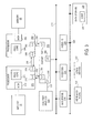
- Figure 1 illustrates a processor in which at least one embodiment of the invention may be used.
- processor 100 having one or more central processing units (CPUs) 105 and 110 and at least one non-CPU functional unit 107 and 113, respectively.
- CPUs central processing units
- non-CPU functional unit 115 which may perform other operations not performed by functional units 107 and 113.
- the functional units 107, 113, and 115 may include functions such as graphics processing, memory control and peripheral control, such as audio, video, disk control, digital signal processing, etc.
- processor 100 may also include other logic not shown in Figure 1 , such as I/O control.
- the processor 100 may be a general purpose CPU.
- the processor may be either a general purpose CPU or hardware that can perform graphics-specific functions within a system that may include both general purpose CPU integrated circuits as well as graphics-specific hardware or other parallel computational hardware.
- general purpose computing becomes more integrated with parallel computational hardware, such as graphics engines, texture samples, etc., the more versatile and location-independent the logic 1 19 becomes.
- logic 119 could include hardware/software or any combination thereof and be located or integrated within or outside of any portion of the processor 100.
- logic 119 includes logic for performing graphics rasterization clip functions. Furthermore, in one embodiment, the logic includes arithmetic logic units (ALUs) found within or associated with single-instruction-multiple-data (SIMD) execution logic. Because embodiments of the invention perform comparative analysis between polygons within and outside of a frustum, operations associated with an embodiment lend themselves to be performed by parallel instruction set architectures (ISAs) and micro-architectures. However, traditional single-instruction-single data architectures/micro-architectures are also suitable for performing embodiments of the invention. In one embodiment, the logic units of processor 100 may be interconnected over a ring interconnect, shared-bus interconnect (e.g., front-side bus), point-to-point (P2P) interconnect, or other interconnect structure.
- ALUs arithmetic logic units
- SIMD single-instruction-multiple-data
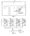
- FIG. 2 illustrates a shared-bus computer system in which one embodiment of the invention may be used.
- Microprocessors 201-215 may contain various functional units, such as one or more CPUs (223, 227, 233, 237, 243, 247, 253, 257), graphics device (207, 217, 227, 237), memory controller (225, 235, 245, 255), I/O control, or other functional units, such as a PCI or PCIe controller (220, 230, 240, 250).
- the system of Figure 2 may also include an I/O controller 265 to interface the microprocessors to peripheral control devices 260.
- the system includes 3D graphics logic, such as a rendering engine, texture sampler, etc., which may include logic to perform at least one embodiment of the invention.
- a peripheral control device may include a graphics device to perform embodiments of the invention.
- Any CPU in the system may also include logic to perform operations associated with embodiments of the invention.
- one or more microprocessors of Figure 2 may include a general purpose processor, graphics processor, or some other type of processor having logic 219 to determine which polygons land within and/or outside of a frustum formed by intersection of given rays and a bounding box of a given node within an acceleration structure, such as a kd-tree.
- some or all of the elements illustrated in Figure 2 may be included in a microprocessor and include other interconnects, such as direct memory interface (DMI), a PCI express graphics (PEG) interconnect, etc. Regardless of configuration, embodiments of the invention may be included or otherwise associated with any portion of the system of Figure 2 .
- DMI direct memory interface
- PEG PCI express graphics
- the system of Figure 2 may also include main memory (not shown), which may be include various memory structures, such as dynamic random-access memory (DRAM), a hard disk drive (HDD), or a memory source located remotely from the computer system via network interface containing various storage devices and technologies.
- main memory may be include various memory structures, such as dynamic random-access memory (DRAM), a hard disk drive (HDD), or a memory source located remotely from the computer system via network interface containing various storage devices and technologies.
- Cache memory within the system of Figure 2 may be located either within a processor or in close proximity to a processor, such as on the processor's local bus.
- P2P point-to-point
- ring interconnect systems may be used in conjunction with various embodiments of the invention, including point-to-point (P2P) interconnect systems and ring interconnect systems.
- the P2P system of Figure 3 may include several processors, of which only two, processors 370, 380 are shown by example.
- Processors 370, 380 may each include a local memory controller hub (MCH) 372, 382 to connect with memory 32, 34.
- MCH local memory controller hub
- Processors 370, 380 may exchange data via a point-to-point (PtP) interface 350 using PtP interface circuits 378, 388.
- PtP point-to-point
- Processors 370, 380 may each exchange data with a chipset 390 via individual PtP interfaces 352, 354 using point to point interface circuits 376, 394, 386, 398.
- Chipset 390 may also exchange data with a high-performance graphics circuit 338 via a high-performance graphics interface 339.
- Embodiments of the invention may be located within any processor having any number of processing cores, or within each of the PtP bus agents of Figure 3 .
- logic 319 may be used to perform operations associated with at least one embodiment of the invention.
- Figure 5 illustrates an acceleration structure that may be used with at least one embodiment of the invention.
- the acceleration structure of Figure 5 is a kd-tree 501, the top-level node of which corresponds to the largest bounding box of a scene, such as the one in Figure 510.
- the lower-level nodes of the kd-tree correspond to progressively smaller bounding boxes of Figure 520.
- Each internal node in Figure 501 has two children at lower level in the tree.
- the acceleration structure of Figure 5 could be quite large depending on the number of polygons in the scene. Therefore, the time and computing resources required to build the acceleration structure may be quite significant.
- a frustum is formed for each of leaf nodes through which packet of rays pass.
- Embodiments of the invention reduce the amount of processing necessary to traverse the acceleration structure and render the image by first determining what polygons need to be tested (i.e., those intersected by the frustum) and which do not (i.e., those within a leaf node that are not intersected by the frustum) and then processing only those polygons intersected by the frustum.
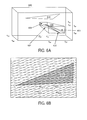
- Figure 6 illustrates a bounding box being intersected by a frustum, wherein at least one embodiment of the invention may be used to determine the polygons that can be ignored and which polygons must be tested and possibly rendered.
- the bounding box 600 is intersected by frustum 605, which contains rays 601, 602, 603, and 604. In other embodiments more or fewer rays may define the frustum.
- a triangle 6 10 which lies outside of the frustum (i.e., is not intersected by the frustum).
- Triangle 610 need not be tested, and therefore excluded from the processing for the given packet. Instead, triangle 610 is ignored, in one embodiment, by performing a culling function to exclude the ray-triangle intersection tests for a given packet while traversing the leaf node housing the triangle.
- the culling is also performed in a plane 620 of a triangle 630 by finding an intersection of a frustum with the plane 620.
- the intersection of frustum 605 with the plane 620 is defined by points 621, 622, 623, and 624.
- by comparing the coordinates of the vertices of triangle 630 with the coordinates of these four points it is possible to detect if triangle lays completely outside of the frustum.
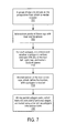
- Figure 7 illustrates a flow diagram of operations that may be used in conjunction with at least one embodiment of the invention, to find all intersections of a packet of rays with polygons (e.g., triangles) inside a leaf node regardless of the processor or system configuration in which the embodiment is used.
- a group of rays are chosen during rending of a scene.
- the resulting rectangles, bounding the rays passing through the bounding box form a frustum containing the intersections of the rays with the node's boundaries.
- each polygon it is determined whether polygon's vertices lays outside of any of the four left, right, top, and bottom frustum planes. If all polygon vertices are outside at least one plane, this polygon is excluded from further processing. Otherwise, at operation 715, an intersection of the four corner rays, which define the frustum, with a polygon plane is computed. Using the coordinates (e.g., barycentric coordinates) of intersection points between the frustum corner rays and the plane, situations can be identified where the frustum is separated from the polygon by any one of the convex polygon edges.
- coordinates e.g., barycentric coordinates
- the left side of the system defines a ray with the origin 'o' and the direction 'd', whereas the right side of the system defines points inside a triangle with vertices 'p 0 ', 'p 1 ', and 'p 2 '.
- 't' is a variable representing a distance to the ray/triangle intersection point from the ray's origin 'o', and barycentric coordinates, 'u' and 'v', of the point inside the triangle.
- a requirement (1) of the system described above is that the intersection point, u 1 ,v 1 , be closer to the ray's origin than the previously found intersection point, u 0 ,v 0 , (as represented by (2)), and within the triangle's boundaries (as represented by (3)).
- the described algorithm presumes the existence of at least one coordinate for which all directions of rays in a packet have the same sign and uses the coordinate with the largest absolute value. This is a significantly weaker requirement than other acceleration structure traversal algorithms (e.g., all directions of each coordinate have the same sign). If there is no prevalent direction for a packet of rays, prior art splitting techniques may be used, although such ray packets may occur very infrequently (and never for primary rays). In at least one embodiment, choosing the most prevalent axis does not affect the accuracy of computations, but may result in improved performance of the algorithm.
- determining whether all polygon vertices lay outside at least one frustum plane may involve using single-instruction-multiple-data (SIMD) multiplication and addition operations for each polygon vertex.
- SIMD single-instruction-multiple-data
- the bottom frustum plane is defined by three points [x 00 , y 00 , z 00 ], [x 00 , y 01 , z 00 ], and [x 10 , y 10 , z 10 ].
- any given vertex, v [v x , v y , v z ] - [x 00 , y 00 , z 00 ]) is negative.
- the absolute value of this expression is not necessary, but only its sign, the first multiplier (y 01 -y 00 ) may be ignored, as it is always positive.
- the above calculations may be repeated for all four frustum planes and represented by 4-component vectors (to facilitate SIMD processing, for example). In one embodiment, this may result in the following algorithm for detecting a separation of polygon's vertices and a frustum:
- q 0 and q 1 may be divided by dx in the above equation to achieve better memory organization and run-time performance, by reducing the number of the stored terms from three to two.
- Operations described in reference to Figure 7 can be performed concurrently with ray packet clipping, in one embodiment.
- the techniques described herein may involve storing the coordinates of node's bounding boxes for all non-empty leaf nodes together with other node data. In other embodiments, bounding box coordinates may be determined dynamically, or "on the fly".
- triangles can be excluded whose vertices are separated from the frustum, according to a technique, such as in operation 710 in Figure 7 . While the frustum is being determined, a packet of 4 rays corresponding to the frustum corners may also be determined. If any of the three conditions discussed in reference to operation 710 in Figure 7 are false for all four rays, then it may determined that the frustum does not intersect the triangle. In one embodiment, if all corner rays do intersect a triangle, then aperture checking could be omitted for all rays in the packet.
- embodiments could further eliminate unnecessary tests by considering near and far frustum planes.
- Near plane is orthogonal to the prevalent axis of the ray packet and passes through the ray's origin with the smallest prevalent coordinate value for rays with positive direction along the prevalent axis and the largest coordinate for negative directions.
- the intersections of four corner frustum rays with such plane can be used to purge triangles that are strictly behind the beam of rays.
- the computed distances could be used to purge all triangles behind the one triangle, in one embodiment.
- the effectiveness of clipping in relation to the far plane may depend on the size of triangles in a scene.
Landscapes
- Engineering & Computer Science (AREA)
- Computer Graphics (AREA)
- Physics & Mathematics (AREA)
- General Physics & Mathematics (AREA)
- Theoretical Computer Science (AREA)
- Image Generation (AREA)
Abstract
Description
- Embodiments of the invention relate generally to the field of computer graphics. More particularly, embodiments of the invention relate to techniques to perform ray tracing within a computer system.
- Ray tracing is a technique that involves finding intersections of given rays with geometric objects in a scene. Ray tracing can be used to create a more pleasing and rich 3D experience compared with traditional rasterization approaches, as it approximates natural light propagation more accurately.
- Because ray tracing may involve many ray-polygon intersection tests , some additional structures, known as "acceleration structures", may be used to minimize the number of ray/polygon intersection tests. Acceleration structures may include linked data arrays containing information about the geometric detail in a 3D scene (e.g., bounding box coordinates), which enables a ray trajectory to be traced through a scene in a more logarithmic amount of time compared to the amount of time necessary to test every ray against every polygon within a scene or object in a scene. There are many types of acceleration structures, including "kd-tree" acceleration structures, which contain "nodes" representing 3D space divided into two sub-spaces by a split plane. In a kd-tree, the leaf nodes of the tree contain polygons intersecting the bounding box of the leaf node. Typically, in an acceleration structure, such as a kd-tree, larger bounding boxes are represented at the highest level of the hierarchy and progressively smaller bounding boxes are at the bottom of the structure.
- Creating acceleration structures, such as kd-trees, can be computationally expensive. Smaller acceleration structures are faster to create, but they eliminate fewer ray-polygon intersection tests. The optimal size of the acceleration structure is dependent on how fast it could be traversed compared with the average speed of the used ray-triangle intersection test.
- Embodiments of the invention are illustrated by way of example, and not by way of limitation, in the figures of the accompanying drawings and in which like reference numerals refer to similar elements and in which:
-
Figure 1 illustrates a block diagram of a processor, in which at least one embodiment of the invention may be used; -
Figure 2 illustrates a block diagram of a shared bus computer system, in which at least one embodiment of the invention may be used; -
Figure 3 illustrates a block diagram a point-to-point interconnect computer system, in which at least one embodiment of the invention may be used; -
Figure 4 illustrates a three-dimensional (3D) image to be rendered according to at least one embodiment; -
Figure 5 illustrates an acceleration structure, which may be used in conjunction with one embodiment; -
Figure 6 illustrates a bounding box being intersected by a frustum and a polygon lying outside the frustum, which may be culled according to one embodiment; -
Figure 7 is a flow diagram illustrating operations that may be used in one embodiment. - Embodiments of the invention may be used in computer systems in which graphics rendering hardware is implemented. Furthermore, embodiments may be used in computer systems or microprocessors in which general purpose central processing units (CPU) are implemented. Moreover, some embodiments may be used in systems or processors in which both graphics processing and general purpose CPU processing are performed by the same or different hardware. In yet further embodiments, operations described herein may be implemented in software, hardware, or some combination thereof.
- In some embodiments, the speed of the traversal of acceleration structures used in the ray tracing algorithms may be improved by techniques described herein. In one embodiment, techniques described herein shorten search trees within the acceleration structure by increasing the size of sub-nodes (or "leaf nodes") to be traversed, thereby reducing the computations necessary to calculate the proper information contained within the acceleration structure as a 3D graphics scene is rendered using ray tracing techniques, and thereby increasing the performance of a 3D graphics application.
- In one embodiment, in which a 3D scene represented in an acceleration structure, such as a kd-tree, for example, the number of polygons to be tested is decreased by determining which polygons do not fall within a sub-space (or "frustum") formed by group of rays. A frustum can be conceptualized as the 3D shape bounded by the intersection of three or more (e.g., 4) planes in a 3D space. By determining which polygons intersect a frustum during traversing the leaf nodes of an acceleration structure, and using the corresponding polygons for ray-polygon tests, significant portion of processing can be avoided, because only the polygons intersecting the frustum are tested.
-
Figure 1 illustrates a processor in which at least one embodiment of the invention may be used. In particular, Figure illustratesprocessor 100 having one or more central processing units (CPUs) 105 and 110 and at least one non-CPU functional unit 107 and 113, respectively. Also illustrated inFigure 1 is at least one other non-CPUfunctional unit 115 which may perform other operations not performed by functional units 107 and 113. In one embodiment, thefunctional units 107, 113, and 115 may include functions such as graphics processing, memory control and peripheral control, such as audio, video, disk control, digital signal processing, etc. In some embodiments,processor 100 may also include other logic not shown inFigure 1 , such as I/O control. In one embodiment, each processor in a multi-processor system or each processor core in a multi-core processor may include or otherwise be associated withlogic 119 to enable techniques to improve speed of ray tracing acceleration structure traversal and corresponding polygon rendering, in accordance with at least one embodiment. In one embodiment, theprocessor 100 is a graphics processor and thelogic 119 is used to help determine which polygons lay outside a frustum defined by rays passing through a given bounding box. In other embodiments, thelogic 119 may include software to help determine which polygon vertices are within or outside of a frustum. In other embodiments, thelogic 119 may include both hardware and software to help determine polygons intersected by or contained within a frustum. - In some embodiments, the
processor 100 may be a general purpose CPU. In other embodiments, the processor may be either a general purpose CPU or hardware that can perform graphics-specific functions within a system that may include both general purpose CPU integrated circuits as well as graphics-specific hardware or other parallel computational hardware. As general purpose computing becomes more integrated with parallel computational hardware, such as graphics engines, texture samples, etc., the more versatile and location-independent the logic 1 19 becomes. As a result,logic 119 could include hardware/software or any combination thereof and be located or integrated within or outside of any portion of theprocessor 100. - In one embodiment,
logic 119 includes logic for performing graphics rasterization clip functions. Furthermore, in one embodiment, the logic includes arithmetic logic units (ALUs) found within or associated with single-instruction-multiple-data (SIMD) execution logic. Because embodiments of the invention perform comparative analysis between polygons within and outside of a frustum, operations associated with an embodiment lend themselves to be performed by parallel instruction set architectures (ISAs) and micro-architectures. However, traditional single-instruction-single data architectures/micro-architectures are also suitable for performing embodiments of the invention. In one embodiment, the logic units ofprocessor 100 may be interconnected over a ring interconnect, shared-bus interconnect (e.g., front-side bus), point-to-point (P2P) interconnect, or other interconnect structure. -
Figure 2 illustrates a shared-bus computer system in which one embodiment of the invention may be used. Microprocessors 201-215 may contain various functional units, such as one or more CPUs (223, 227, 233, 237, 243, 247, 253, 257), graphics device (207, 217, 227, 237), memory controller (225, 235, 245, 255), I/O control, or other functional units, such as a PCI or PCIe controller (220, 230, 240, 250). The system ofFigure 2 may also include an I/O controller 265 to interface the microprocessors toperipheral control devices 260. - In one embodiment, the system includes 3D graphics logic, such as a rendering engine, texture sampler, etc., which may include logic to perform at least one embodiment of the invention. Furthermore, in other embodiments, a peripheral control device may include a graphics device to perform embodiments of the invention. Any CPU in the system may also include logic to perform operations associated with embodiments of the invention. In one embodiment, one or more microprocessors of
Figure 2 may include a general purpose processor, graphics processor, or some other type ofprocessor having logic 219 to determine which polygons land within and/or outside of a frustum formed by intersection of given rays and a bounding box of a given node within an acceleration structure, such as a kd-tree. - In some embodiments, some or all of the elements illustrated in
Figure 2 may be included in a microprocessor and include other interconnects, such as direct memory interface (DMI), a PCI express graphics (PEG) interconnect, etc. Regardless of configuration, embodiments of the invention may be included or otherwise associated with any portion of the system ofFigure 2 . - The system of
Figure 2 may also include main memory (not shown), which may be include various memory structures, such as dynamic random-access memory (DRAM), a hard disk drive (HDD), or a memory source located remotely from the computer system via network interface containing various storage devices and technologies. Cache memory within the system ofFigure 2 may be located either within a processor or in close proximity to a processor, such as on the processor's local bus. - Furthermore, the cache memory may contain relatively fast memory cells, such as a six-transistor (6T) cell, or other memory cell of approximately equal or faster access speed.
- In addition to the shared-bus computer system illustrated in
Figure 2 , other system configurations may be used in conjunction with various embodiments of the invention, including point-to-point (P2P) interconnect systems and ring interconnect systems. The P2P system ofFigure 3 , for example, may include several processors, of which only two,processors Processors memory Processors interface 350 usingPtP interface circuits Processors chipset 390 via individual PtP interfaces 352, 354 using point to pointinterface circuits Chipset 390 may also exchange data with a high-performance graphics circuit 338 via a high-performance graphics interface 339. Embodiments of the invention may be located within any processor having any number of processing cores, or within each of the PtP bus agents ofFigure 3 . In one embodiment, logic 319 may be used to perform operations associated with at least one embodiment of the invention. -
Figure 4 illustrates an image that may be rendered according to one embodiment, using global illumination technique. Multiple rays per pixel have to be traced to achieve this image quality. -
Figure 5 illustrates an acceleration structure that may be used with at least one embodiment of the invention. The acceleration structure ofFigure 5 is a kd-tree 501, the top-level node of which corresponds to the largest bounding box of a scene, such as the one in Figure 510. The lower-level nodes of the kd-tree correspond to progressively smaller bounding boxes of Figure 520. Each internal node in Figure 501 has two children at lower level in the tree. The acceleration structure ofFigure 5 could be quite large depending on the number of polygons in the scene. Therefore, the time and computing resources required to build the acceleration structure may be quite significant. - In one embodiment, a frustum is formed for each of leaf nodes through which packet of rays pass. Embodiments of the invention reduce the amount of processing necessary to traverse the acceleration structure and render the image by first determining what polygons need to be tested (i.e., those intersected by the frustum) and which do not (i.e., those within a leaf node that are not intersected by the frustum) and then processing only those polygons intersected by the frustum.
-
Figure 6 illustrates a bounding box being intersected by a frustum, wherein at least one embodiment of the invention may be used to determine the polygons that can be ignored and which polygons must be tested and possibly rendered. InFigure 6 , thebounding box 600 is intersected byfrustum 605, which containsrays Triangle 610 need not be tested, and therefore excluded from the processing for the given packet. Instead,triangle 610 is ignored, in one embodiment, by performing a culling function to exclude the ray-triangle intersection tests for a given packet while traversing the leaf node housing the triangle. - In one embodiment, the culling is also performed in a plane 620 of a
triangle 630 by finding an intersection of a frustum with the plane 620. The intersection offrustum 605 with the plane 620 is defined bypoints triangle 630 with the coordinates of these four points it is possible to detect if triangle lays completely outside of the frustum. -
Figure 7 illustrates a flow diagram of operations that may be used in conjunction with at least one embodiment of the invention, to find all intersections of a packet of rays with polygons (e.g., triangles) inside a leaf node regardless of the processor or system configuration in which the embodiment is used. Atoperation 701, a group of rays are chosen during rending of a scene. Atoperation 705, the intersection points of these rays with near and far planes (x = x00 and x = x10 planes ofFigure 6 ) of the bounding box of traversed node are found and the axis-aligned rectangles containing these intersections for each plane are calculated. The resulting rectangles, bounding the rays passing through the bounding box, form a frustum containing the intersections of the rays with the node's boundaries. - At operation 710, for each polygon, it is determined whether polygon's vertices lays outside of any of the four left, right, top, and bottom frustum planes. If all polygon vertices are outside at least one plane, this polygon is excluded from further processing. Otherwise, at operation 715, an intersection of the four corner rays, which define the frustum, with a polygon plane is computed. Using the coordinates (e.g., barycentric coordinates) of intersection points between the frustum corner rays and the plane, situations can be identified where the frustum is separated from the polygon by any one of the convex polygon edges. Optionally, two additional frustum planes (near and far) could be inspected at this stage to eliminate polygons which are either behind the point of perspective (near plane) or further away than the previously found intersecting polygon (far plane). At
operation 720, all ray packet-polygon pairs, which were not excluded at previous stages, are tested using prior art ray-polygon intersection tests. In other embodiments other methods may be used to find polygon intersection points with the ray packet or frustum. - In one embodiment, finding the intersection of a ray and a triangle is equivalent to solving a linear system of three equations represented by :


- In one embodiment, the described algorithm presumes the existence of at least one coordinate for which all directions of rays in a packet have the same sign and uses the coordinate with the largest absolute value. This is a significantly weaker requirement than other acceleration structure traversal algorithms (e.g., all directions of each coordinate have the same sign). If there is no prevalent direction for a packet of rays, prior art splitting techniques may be used, although such ray packets may occur very infrequently (and never for primary rays). In at least one embodiment, choosing the most prevalent axis does not affect the accuracy of computations, but may result in improved performance of the algorithm.
- In one embodiment, determining whether all polygon vertices lay outside at least one frustum plane may involve using single-instruction-multiple-data (SIMD) multiplication and addition operations for each polygon vertex. As illustrated on
Figure 6 , the bottom frustum plane is defined by three points [x00, y00, z00], [x00, y01, z00], and [x10, y10, z10]. Its normal is given by the following cross product:

- Because [x00, y00, z00] lies in the frustum plane, any given vertex, v = [vx, vy, vz], will necessarily lie outside the frustum plane (and therefore the frustum) if the dot product, nb.([vx, vy, vz] - [x00, y00, z00]) is negative. This relationship may be expanded and simplified to the expression:

- Because, in one embodiment, the absolute value of this expression is not necessary, but only its sign, the first multiplier (y01-y00) may be ignored, as it is always positive. The above calculations may be repeated for all four frustum planes and represented by 4-component vectors (to facilitate SIMD processing, for example). In one embodiment, this may result in the following algorithm for detecting a separation of polygon's vertices and a frustum:
- (1) For each ray packet, compute two SIMD vectors q0 and q1 for each instance the packet traverses a node (bounding box) according to the equations:


- (2) For each vertex v = [vx, vy, vz], the four components of the SIMD variable, the distance, d = [vz, -vy, -vz, vy] + [vx, vx, vx, vx] q1 + q0, will be proportional to the distances to the four frustum planes.
- (3) If at least one component of the distance is negative for all polygon vertices, the polygon may be considered to be separated from the frustum by the corresponding frustum plane, which can be determined, in one embodiment, using mask extraction operations (e.g., "MOVEMSK").
- In one embodiment, q0 and q1 may be divided by dx in the above equation to achieve better memory organization and run-time performance, by reducing the number of the stored terms from three to two. Operations described in reference to
Figure 7 can be performed concurrently with ray packet clipping, in one embodiment. In one embodiment, in which kd-trees are used as the acceleration structure, the techniques described herein may involve storing the coordinates of node's bounding boxes for all non-empty leaf nodes together with other node data. In other embodiments, bounding box coordinates may be determined dynamically, or "on the fly". - In one embodiment, triangles can be excluded whose vertices are separated from the frustum, according to a technique, such as in operation 710 in
Figure 7 . While the frustum is being determined, a packet of 4 rays corresponding to the frustum corners may also be determined. If any of the three conditions discussed in reference to operation 710 inFigure 7 are false for all four rays, then it may determined that the frustum does not intersect the triangle. In one embodiment, if all corner rays do intersect a triangle, then aperture checking could be omitted for all rays in the packet. - In addition to four frustum planes, embodiments could further eliminate unnecessary tests by considering near and far frustum planes. Near plane is orthogonal to the prevalent axis of the ray packet and passes through the ray's origin with the smallest prevalent coordinate value for rays with positive direction along the prevalent axis and the largest coordinate for negative directions. The intersections of four corner frustum rays with such plane can be used to purge triangles that are strictly behind the beam of rays. Similarly, if all four frustum corner rays intersect one triangle, the computed distances could be used to purge all triangles behind the one triangle, in one embodiment. In some embodiments, the effectiveness of clipping in relation to the far plane may depend on the size of triangles in a scene.
- One or more aspects of at least one embodiment may be implemented by representative data stored on a machine-readable medium which represents various logic within the processor, which when read by a machine causes the machine to fabricate logic to perform the techniques described herein. Such representations, known as "IP cores" may be stored on a tangible, machine readable medium ("tape") and supplied to various customers or manufacturing facilities to load into the fabrication machines that actually make the logic or processor.
- Thus, a method and apparatus for directing micro-architectural memory region accesses has been described. It is to be understood that the above description is intended to be illustrative and not restrictive. Many other embodiments will be apparent to those of skill in the art upon reading and understanding the above description. The scope of the invention should, therefore, be determined with reference to the appended claims, along with the full scope of equivalents to which such claims are entitled. A summary of the foregoing disclosure is set out in the following clauses:-
- 1. An apparatus comprising:
- logic to determine whether a polygon within a bounding box of a three-dimensional (3D) graphics scene to be rendered intersects with a frustum bounded by a plurality of entry and exit points of a plurality of rays passing through the bounding box, wherein the determination is to at least partially control the number of tested ray-polygon combinations.
- 2. The apparatus of clause 1, wherein the polygon is to be ignored for the plurality of rays, in response to the logic determining that the polygon does not intersect the frustum.
- 3. The apparatus of clause 1, wherein the acceleration structure contains nodes bounded by 3D boxes which are used together with a plurality of rays to form the said frustum.
- 4. The apparatus of clause 2, wherein the logic is to implement a clipping function to determine whether the polygon intersects the frustum.
- 5. The apparatus of clause 4, wherein the clipping function includes performing a single-instruction-multiple-data (SIMD) operation on information corresponding to the plurality of rays.
- 6. The apparatus of clause 5, wherein the SIMD operation includes at least one of a group of SIMD operations consisting of: a packed multiply-add instruction, a packed multiply instruction and a packed addition instruction.
- 7. The apparatus of clause 1, wherein the logic includes a 3D graphics acceleration integrated circuit.
- 8. The apparatus of clause 7, wherein the 3D graphics acceleration integrated circuit includes logic for accelerating a ray tracing algorithm.
- 9. A method comprising:
- choosing a group of rays which are used for rendering of a three dimensional
(3D) graphics object; - building an acceleration structure for this object, comprised of plurality of
bounding boxes; - determining intersection points of the rays with near and far planes of a bounding
box of an acceleration structure; - forming a frustum which contains intersections of plurality of rays with
a bounding box; - determining whether any of a polygon's vertices lays outside planes of a
frustum whose boundaries are defined by the rays; - excluding from further processing polygons which are not intersecting the
frustum.
- choosing a group of rays which are used for rendering of a three dimensional
- 10. The method of clause 9, wherein determining whether any of a polygon's vertices lays outside any of four frustum planes includes computing 4-wide SIMD expression, which is proportional to the distances to the four frustum planes.
- 11. The method of clause 10, wherein the signs of the computed SIMD expressions for all polygon vertices are used to find out if all vertices are outside at least one frustum plane.
- 12. The method of clause 9 wherein two additional frustum planes are formed by near and far planes orthogonal to the prevalent direction of rays inside the packet.
- 13. The method of clause 9 wherein further tests are performed inside polygon plane to determine if the frustum is separated from the polygon by at least one polygon edge.
- 14. The method of clause 10, further comprising performing single-instruction-multiple data (SIMD) operations to determine the separation of the frustum with the polygon.
- 15. The method of clause 13, wherein the SIMD operation includes at least one of a group of SIMD operations consisting of: a packed multiply-add instruction, a packed multiply instruction and a packed addition instruction.
- 16. The method of clause 9, further comprising performing a ray tracing algorithm wherein plurality of ray-triangle intersection tests are excluded from further processing.
- 17. The method of clause 16, further comprising rendering a 3D object.
- 18. A system comprising:
- a memory to store textures for a three dimensional (3D) graphics object;
- a graphics device to apply the textures to the 3D graphics object, the graphics
device including culling logic to cull a plurality of triangles from a bounding box that do not intersect a frustum within the bounding box before applying the textures to a plurality of triangles that intersect with frustum; - a display controller to project the object onto a display device.
- 19. The system of clause 18, wherein the memory is to store an acceleration structure including at least one node corresponding to the bounding box.
- 20. The system of clause 18, wherein the acceleration structure includes a plurality of nodes corresponding to a plurality of bounding boxes corresponding to the 3D graphics object.
- 21. The system of clause 18, wherein the amount of computations during traversing of the acceleration structure is controlled, at least in part, by the culling logic.
- 22. The system of clause 21, further comprising at least one processor core which is capable of executing culling instructions.
Claims (15)
- A graphics processing apparatus comprising:logic to determine whether a polygon within a bounding box of a three-dimensional (3D) graphics scene to be rendered intersects with a frustum bounded by a plurality of entry and exit points of a plurality of rays passing through the bounding box, wherein the determination is to at least partially control the number of tested ray-polygon combinations.
- The apparatus of claim 1, wherein the polygon is to be ignored for the plurality of rays, in response to the logic determining that the polygon does not intersect the frustum.
- The apparatus of claim 1, wherein the acceleration structure contains nodes bounded by 3D boxes which are used together with a plurality of rays to form the said frustum.
- The apparatus of claim 2, wherein:the logic is to implement a clipping function to determine whether the polygon intersects the frustum;the clipping function includes performing a single-instruction-multiple-data (SIMD) operation on information corresponding to the plurality of rays; andthe SIMD operation includes at least one of a group of SIMD operations consisting of: a packed multiply-add instruction, a packed multiply instruction and a packed addition instruction.
- The apparatus of claim 1, wherein the logic includes a 3D graphics acceleration integrated circuit for accelerating a ray tracing algorithm.
- A method of graphics processing comprising:choosing a group of rays which are used for rendered of a three-dimensional (3D graphics object;building an acceleration structure for this object, comprised of plurality of bounding boxes;determining intersection points of the rays with near and far planes of a bounding box of an acceleration structure;forming a frustum which contains intersections of plurality of rays with a bounding box;determining whether any of a polygon's vertices lays outside planes of a frustum whose boundaries are defined by the rays;excluding from further processing polygons which are not intersecting the frustum.
- The method of claim 6, wherein:determining whether any of a polygon's vertices lays outside any of four frustum planes includes computer 4-wide SIMD expression, which is proportional to the distances to the four frustum planes; andthe signs of the computer SIMD expressions for all polygon vertices are used to find out if all vertices are outside at least one frustum place.
- The method of claim 6 wherein two additional frustum planes are formed by near and far planes orthogonal to the prevalent direction of rays inside the packet.
- The method of claim 6 wherein:further tests are performed inside polygon place to determine if the frustum is separated from the polygon by at least one polygon edge; andthe SIMD operation includes at least one of a group of SIMD operations consisting of: a packed multiply-add instruction, a packed multiply instruction and a packed addition instruction.
- The method of claim 7, further comprising performing single-instruction-multiple data (SIMD) operations to determine the separation of the frustum with the polygon.
- The method of claim 6, further comprising:performing a ray tracing algorithm wherein plurality of ray-triangle intersection tests are excluded from further processing; andrendering a 3D object.
- A system comprising:a memory to store textures for a three dimensional (3D) graphics object:a graphics device to apply the textures to the 3D graphics object, the graphics device including culling logic to cull a plurality of triangles from a bounding box that do not intersect a frustum within the bounding box before applying the textures to a plurality of triangles that intersect with frustum;a display controller to project the object onto a display device.
- The system of claim 12, wherein:the memory is to store an acceleration structure including at least one node corresponding to the bounding box; andthe acceleration structure includes a plurality of nodes corresponding to a plurality of bounding boxes corresponding to the 3D graphics object.
- The system of claim 12, wherein the amount of computations during traversing of the acceleration structure is controlled, at least in part, by the culling logic.
- The system of claim 14, further comprising at least one processor core which is capable of executing culling instructions.
Applications Claiming Priority (1)
| Application Number | Priority Date | Filing Date | Title |
|---|---|---|---|
| US12/041,229 US8390618B2 (en) | 2008-03-03 | 2008-03-03 | Technique for improving ray tracing performance |
Publications (1)
| Publication Number | Publication Date |
|---|---|
| EP2098996A1 true EP2098996A1 (en) | 2009-09-09 |
Family
ID=40766051
Family Applications (1)
| Application Number | Title | Priority Date | Filing Date |
|---|---|---|---|
| EP09250594A Withdrawn EP2098996A1 (en) | 2008-03-03 | 2009-03-02 | Technique for improving ray tracing performance |
Country Status (3)
| Country | Link |
|---|---|
| US (1) | US8390618B2 (en) |
| EP (1) | EP2098996A1 (en) |
| CN (1) | CN101527052A (en) |
Families Citing this family (22)
| Publication number | Priority date | Publication date | Assignee | Title |
|---|---|---|---|---|
| US8963918B2 (en) * | 2008-09-30 | 2015-02-24 | Microsoft Corporation | Ray tracing on graphics hardware using kd-trees |
| KR101004110B1 (en) * | 2009-05-28 | 2010-12-27 | 주식회사 실리콘아츠 | Ray tracing core and ray tracing chip comprising the same |
| KR100975128B1 (en) * | 2010-01-11 | 2010-08-11 | (주)올라웍스 | Method, system and computer-readable recording medium for providing information of object using viewing frustum |
| US8587585B2 (en) * | 2010-09-28 | 2013-11-19 | Intel Corporation | Backface culling for motion blur and depth of field |
| CN102074039B (en) * | 2010-09-29 | 2012-12-19 | 深圳市蓝韵网络有限公司 | Method for drawing volume rendering cutting surface |
| CN101982838B (en) * | 2010-11-02 | 2012-06-27 | 长春理工大学 | 3D virtual set ray tracking method for accelerating back light source irradiation |
| CN102074041B (en) * | 2010-12-21 | 2012-10-10 | 长春理工大学 | Method for drawing planar caustic effect of 3D virtual scene produced by specular reflection |
| US9218679B2 (en) * | 2012-10-08 | 2015-12-22 | Intel Corporation | Reduced bitcount polygon rasterization |
| DE112013005255T5 (en) * | 2012-11-02 | 2015-09-24 | Imagination Technologies Ltd. | If necessary, geometry and acceleration structure generation |
| CN104112293B (en) * | 2014-07-04 | 2017-05-17 | 南京航空航天大学 | Ray tracing acceleration method applied to tunnel environment |
| US9607425B2 (en) | 2014-10-17 | 2017-03-28 | Qualcomm Incorporated | Ray-box intersection testing using dot product-based fixed function logic |
| CN105117533B (en) * | 2015-08-03 | 2018-05-22 | 常州赞云软件科技有限公司 | The accelerated method of Ray Tracing Algorithm in house ornamentation design software |
| US11295506B2 (en) * | 2015-09-16 | 2022-04-05 | Tmrw Foundation Ip S. À R.L. | Chip with game engine and ray trace engine |
| US11010956B2 (en) | 2015-12-09 | 2021-05-18 | Imagination Technologies Limited | Foveated rendering |
| KR102853351B1 (en) * | 2016-11-04 | 2025-08-29 | 삼성전자주식회사 | METHOD AND APPARATUS for generating acceleration structure |
| US10885698B2 (en) * | 2018-08-10 | 2021-01-05 | Nvidia Corporation | Method for programmable timeouts of tree traversal mechanisms in hardware |
| KR102483023B1 (en) * | 2020-11-25 | 2022-12-30 | 한국전자통신연구원 | Apparatus and method for selecting path through beam search |
| GB2599188B (en) * | 2021-03-23 | 2022-10-12 | Imagination Tech Ltd | Intersection testing in a ray tracing system |
| GB2599183B (en) | 2021-03-23 | 2022-10-12 | Imagination Tech Ltd | Intersection testing in a ray tracing system |
| GB2599187B (en) | 2021-03-23 | 2022-09-21 | Imagination Tech Ltd | Intersection testing in a ray tracing system |
| US11954788B2 (en) * | 2021-12-28 | 2024-04-09 | Advanced Micro Devices, Inc. | Variable width bounding volume hierarchy nodes |
| CN115591240B (en) * | 2022-12-01 | 2023-04-07 | 腾讯科技(深圳)有限公司 | Feature extraction method, device and equipment for three-dimensional game scene and storage medium |
Citations (2)
| Publication number | Priority date | Publication date | Assignee | Title |
|---|---|---|---|---|
| WO2007070456A2 (en) * | 2005-12-12 | 2007-06-21 | Intel Corporation | Method and apparatus for binary image classification and segmentation |
| WO2008011391A2 (en) * | 2006-07-21 | 2008-01-24 | University Of Utah Research Foundation | Ray tracing a three-dimensional scene using a hierarchical data structure |
Family Cites Families (5)
| Publication number | Priority date | Publication date | Assignee | Title |
|---|---|---|---|---|
| US7659894B2 (en) * | 2000-06-19 | 2010-02-09 | Mental Images Gmbh | Terminating spatial partition hierarchies by a priori bounding memory |
| US8411088B2 (en) * | 2000-06-19 | 2013-04-02 | Nvidia Corporation | Accelerated ray tracing |
| US7495664B2 (en) * | 2000-06-19 | 2009-02-24 | Mental Images Gmbh | Instant ray tracing |
| US7952583B2 (en) * | 2000-06-19 | 2011-05-31 | Mental Images Gmbh | Quasi-monte carlo light transport simulation by efficient ray tracing |
| US8384711B2 (en) * | 2006-11-29 | 2013-02-26 | The University Of Utah Research Foundation | Ray tracing a three dimensional scene using a grid |
-
2008
- 2008-03-03 US US12/041,229 patent/US8390618B2/en not_active Expired - Fee Related
-
2009
- 2009-03-02 EP EP09250594A patent/EP2098996A1/en not_active Withdrawn
- 2009-03-03 CN CN200910118299A patent/CN101527052A/en active Pending
Patent Citations (2)
| Publication number | Priority date | Publication date | Assignee | Title |
|---|---|---|---|---|
| WO2007070456A2 (en) * | 2005-12-12 | 2007-06-21 | Intel Corporation | Method and apparatus for binary image classification and segmentation |
| WO2008011391A2 (en) * | 2006-07-21 | 2008-01-24 | University Of Utah Research Foundation | Ray tracing a three-dimensional scene using a hierarchical data structure |
Non-Patent Citations (7)
| Title |
|---|
| ALEXANDER RESHETOV ED - ANONYMOUS: "Faster Ray Packets - Triangle Intersection through Vertex Culling", INTERACTIVE RAY TRACING, 2007. RT '07. IEEE SYMPOSIUM ON, IEEE, PI, 1 September 2007 (2007-09-01), pages 105 - 112, XP031142291, ISBN: 978-1-4244-1629-5 * |
| ALEXANDER RESHETOV: "Faster Ray Packet-Triangle Intersection through Vertex Culling", IEEE/EG SYMPOSIUM ON INTERACTIVE RAY TRACING, September 2007 (2007-09-01), pages 10 - 12 |
| INGO WALD ET AL., RAY TRACING ANIMATED SCENES USING COHERENT GRID TRAVERSAL |
| INGO WALD ET AL: "State of the Art in Ray Tracing Animated Scenes", EUROGRAPHICS TECHNICAL REPORT SERIES, EUROGRAPHICS, AIRE-LA-VILLE, FR, 1 September 2007 (2007-09-01), pages 89 - 116, XP007908773, ISSN: 1017-4656 * |
| SVEN WOOP ET AL: "Estimating Performance of a Ray-Tracing ASIC Design", INTERACTIVE RAY TRACING 2006, IEEE SYMPOSIUM ON, IEEE, PI, 1 September 2006 (2006-09-01), pages 7 - 14, XP031008766, ISBN: 978-1-4244-0693-7 * |
| WALD I ET AL: "Ray tracing animated scenes using coherent grid traversal", ACM TRANSACTIONS ON GRAPHICS, ACM, US, vol. 25, no. 3, 1 July 2006 (2006-07-01), pages 485 - 493, XP007908971, ISSN: 0730-0301 * |
| WALD I ET AL: "Ray tracing deformable scenes using dynamic bounding volume hierarchies", ACM TRANSACTIONS ON GRAPHICS, ACM, US, vol. 26, no. 1, 1 January 2007 (2007-01-01), pages 18pp, XP007908972, ISSN: 0730-0301 * |
Also Published As
| Publication number | Publication date |
|---|---|
| US8390618B2 (en) | 2013-03-05 |
| CN101527052A (en) | 2009-09-09 |
| US20090219285A1 (en) | 2009-09-03 |
Similar Documents
| Publication | Publication Date | Title |
|---|---|---|
| US8390618B2 (en) | Technique for improving ray tracing performance | |
| US10692271B1 (en) | Robust ray-triangle intersection | |
| US11715255B2 (en) | Intersection testing in a ray tracing system using ray bundle vectors | |
| EP4118625B1 (en) | Ray-tracing multi-sample anti-aliasing | |
| US11010963B2 (en) | Realism of scenes involving water surfaces during rendering | |
| US8400447B1 (en) | Space partitioning trees using planes selected from a discrete set of orientations | |
| US8963920B2 (en) | Image processing apparatus and method | |
| US20240371077A1 (en) | Intersection testing in a ray tracing system using multiple ray bundle intersection tests | |
| GB2607350A (en) | Graphics processing | |
| US12159341B2 (en) | Common circuitry for triangle intersection and instance transformation for ray tracing | |
| US10706609B1 (en) | Efficient data path for ray triangle intersection | |
| US20250209723A1 (en) | System and Method for Low-precision Ray Tests | |
| US9569878B2 (en) | Sample culling based on linearized 5D edge equations | |
| Zhdanov et al. | The backward photon mapping for the realistic image rendering | |
| Cook et al. | Image-space visibility ordering for cell projection volume rendering of unstructured data | |
| EP4113449A1 (en) | Intersection testing in a ray tracing system | |
| EP4583059A1 (en) | Intersection testing in a ray tracing system | |
| Dévai | An optimal hidden-surface algorithm and its parallelization | |
| Cunha et al. | Revisiting the visibility problem with a hybrid structure paradigm |
Legal Events
| Date | Code | Title | Description |
|---|---|---|---|
| PUAI | Public reference made under article 153(3) epc to a published international application that has entered the european phase |
Free format text: ORIGINAL CODE: 0009012 |
|
| 17P | Request for examination filed |
Effective date: 20090330 |
|
| AK | Designated contracting states |
Kind code of ref document: A1 Designated state(s): AT BE BG CH CY CZ DE DK EE ES FI FR GB GR HR HU IE IS IT LI LT LU LV MC MK MT NL NO PL PT RO SE SI SK TR |
|
| AX | Request for extension of the european patent |
Extension state: AL BA RS |
|
| 17Q | First examination report despatched |
Effective date: 20091014 |
|
| AKX | Designation fees paid |
Designated state(s): AT BE BG CH CY CZ DE DK EE ES FI FR GB GR HR HU IE IS IT LI LT LU LV MC MK MT NL NO PL PT RO SE SI SK TR |
|
| STAA | Information on the status of an ep patent application or granted ep patent |
Free format text: STATUS: THE APPLICATION IS DEEMED TO BE WITHDRAWN |
|
| 18D | Application deemed to be withdrawn |
Effective date: 20100713 |