EP2098993A1 - Volume measurement in an ultrasound system - Google Patents
Volume measurement in an ultrasound system Download PDFInfo
- Publication number
- EP2098993A1 EP2098993A1 EP09002352A EP09002352A EP2098993A1 EP 2098993 A1 EP2098993 A1 EP 2098993A1 EP 09002352 A EP09002352 A EP 09002352A EP 09002352 A EP09002352 A EP 09002352A EP 2098993 A1 EP2098993 A1 EP 2098993A1
- Authority
- EP
- European Patent Office
- Prior art keywords
- interest
- contour
- slices
- reference plane
- unit
- Prior art date
- Legal status (The legal status is an assumption and is not a legal conclusion. Google has not performed a legal analysis and makes no representation as to the accuracy of the status listed.)
- Withdrawn
Links
Images



Classifications
-
- A—HUMAN NECESSITIES
- A61—MEDICAL OR VETERINARY SCIENCE; HYGIENE
- A61B—DIAGNOSIS; SURGERY; IDENTIFICATION
- A61B8/00—Diagnosis using ultrasonic, sonic or infrasonic waves
- A61B8/08—Clinical applications
-
- A—HUMAN NECESSITIES
- A61—MEDICAL OR VETERINARY SCIENCE; HYGIENE
- A61B—DIAGNOSIS; SURGERY; IDENTIFICATION
- A61B8/00—Diagnosis using ultrasonic, sonic or infrasonic waves
- A61B8/13—Tomography
-
- A—HUMAN NECESSITIES
- A61—MEDICAL OR VETERINARY SCIENCE; HYGIENE
- A61B—DIAGNOSIS; SURGERY; IDENTIFICATION
- A61B5/00—Measuring for diagnostic purposes; Identification of persons
- A61B5/103—Measuring devices for testing the shape, pattern, colour, size or movement of the body or parts thereof, for diagnostic purposes
- A61B5/107—Measuring physical dimensions, e.g. size of the entire body or parts thereof
- A61B5/1075—Measuring physical dimensions, e.g. size of the entire body or parts thereof for measuring dimensions by non-invasive methods, e.g. for determining thickness of tissue layer
-
- A—HUMAN NECESSITIES
- A61—MEDICAL OR VETERINARY SCIENCE; HYGIENE
- A61B—DIAGNOSIS; SURGERY; IDENTIFICATION
- A61B8/00—Diagnosis using ultrasonic, sonic or infrasonic waves
-
- A—HUMAN NECESSITIES
- A61—MEDICAL OR VETERINARY SCIENCE; HYGIENE
- A61B—DIAGNOSIS; SURGERY; IDENTIFICATION
- A61B8/00—Diagnosis using ultrasonic, sonic or infrasonic waves
- A61B8/48—Diagnostic techniques
- A61B8/483—Diagnostic techniques involving the acquisition of a 3D volume of data
-
- G—PHYSICS
- G01—MEASURING; TESTING
- G01S—RADIO DIRECTION-FINDING; RADIO NAVIGATION; DETERMINING DISTANCE OR VELOCITY BY USE OF RADIO WAVES; LOCATING OR PRESENCE-DETECTING BY USE OF THE REFLECTION OR RERADIATION OF RADIO WAVES; ANALOGOUS ARRANGEMENTS USING OTHER WAVES
- G01S15/00—Systems using the reflection or reradiation of acoustic waves, e.g. sonar systems
- G01S15/88—Sonar systems specially adapted for specific applications
- G01S15/89—Sonar systems specially adapted for specific applications for mapping or imaging
- G01S15/8906—Short-range imaging systems; Acoustic microscope systems using pulse-echo techniques
- G01S15/8993—Three dimensional imaging systems
-
- G—PHYSICS
- G01—MEASURING; TESTING
- G01S—RADIO DIRECTION-FINDING; RADIO NAVIGATION; DETERMINING DISTANCE OR VELOCITY BY USE OF RADIO WAVES; LOCATING OR PRESENCE-DETECTING BY USE OF THE REFLECTION OR RERADIATION OF RADIO WAVES; ANALOGOUS ARRANGEMENTS USING OTHER WAVES
- G01S7/00—Details of systems according to groups G01S13/00, G01S15/00, G01S17/00
- G01S7/52—Details of systems according to groups G01S13/00, G01S15/00, G01S17/00 of systems according to group G01S15/00
- G01S7/52017—Details of systems according to groups G01S13/00, G01S15/00, G01S17/00 of systems according to group G01S15/00 particularly adapted to short-range imaging
- G01S7/52053—Display arrangements
- G01S7/52057—Cathode ray tube displays
- G01S7/5206—Two-dimensional coordinated display of distance and direction; B-scan display
- G01S7/52063—Sector scan display
-
- G—PHYSICS
- G06—COMPUTING OR CALCULATING; COUNTING
- G06T—IMAGE DATA PROCESSING OR GENERATION, IN GENERAL
- G06T7/00—Image analysis
- G06T7/60—Analysis of geometric attributes
- G06T7/62—Analysis of geometric attributes of area, perimeter, diameter or volume
-
- G—PHYSICS
- G06—COMPUTING OR CALCULATING; COUNTING
- G06T—IMAGE DATA PROCESSING OR GENERATION, IN GENERAL
- G06T2207/00—Indexing scheme for image analysis or image enhancement
- G06T2207/10—Image acquisition modality
- G06T2207/10132—Ultrasound image
- G06T2207/10136—3D ultrasound image
-
- G—PHYSICS
- G06—COMPUTING OR CALCULATING; COUNTING
- G06T—IMAGE DATA PROCESSING OR GENERATION, IN GENERAL
- G06T2207/00—Indexing scheme for image analysis or image enhancement
- G06T2207/20—Special algorithmic details
- G06T2207/20092—Interactive image processing based on input by user
- G06T2207/20108—Interactive selection of 2D slice in a 3D data set
-
- G—PHYSICS
- G06—COMPUTING OR CALCULATING; COUNTING
- G06T—IMAGE DATA PROCESSING OR GENERATION, IN GENERAL
- G06T2207/00—Indexing scheme for image analysis or image enhancement
- G06T2207/20—Special algorithmic details
- G06T2207/20112—Image segmentation details
- G06T2207/20156—Automatic seed setting
-
- G—PHYSICS
- G06—COMPUTING OR CALCULATING; COUNTING
- G06T—IMAGE DATA PROCESSING OR GENERATION, IN GENERAL
- G06T2207/00—Indexing scheme for image analysis or image enhancement
- G06T2207/20—Special algorithmic details
- G06T2207/20112—Image segmentation details
- G06T2207/20168—Radial search
-
- G—PHYSICS
- G06—COMPUTING OR CALCULATING; COUNTING
- G06T—IMAGE DATA PROCESSING OR GENERATION, IN GENERAL
- G06T2207/00—Indexing scheme for image analysis or image enhancement
- G06T2207/30—Subject of image; Context of image processing
- G06T2207/30004—Biomedical image processing
Definitions
- the present disclosure relates to ultrasound systems, and more particularly to volume measurement in an ultrasound system.
- the ultrasound system operates in various image modes such as a brightness mode, a Doppler mode and the like to acquire ultrasound images for diagnosis. Also, the ultrasound system may operate in a measure mode for measuring volumes of parts of interest (e.g., organs, lesions, etc.) contained in a target object. Volume data, which are usually acquired in the brightness mode, may be used to measure the volumes of parts of interest.
- a measure mode for measuring volumes of parts of interest (e.g., organs, lesions, etc.) contained in a target object.
- Volume data which are usually acquired in the brightness mode, may be used to measure the volumes of parts of interest.
- the ultrasound system allows a user to input a selection instruction for selecting a reference plane from the volume data. Further, a slice setting instruction for setting a plurality of slices, which are perpendicular to the reference plane and parallel to each other, is inputted. The ultrasound system then sets a seed point at a center of each of the slices to extract a contour of the part of interest on each of the slices. The ultrasound system measures the volume of part of interest based on the extracted contours of the part of interest.
- an ultrasound system comprises a volume data forming unit for forming volume data based on ultrasound echoes reflected from a target object, the target object including at least one part of interest; an interface unit for allowing a user to input a selection instruction for selecting a reference plane from the volume data and a slice setting instruction for setting a plurality of slices perpendicular to the reference plane in the volume data; an image processing unit for detecting a contour of the part of interest on the reference plane and determining intersection points of the detected contour and each of the slices as seed points, the image processing unit being further configured to detect contours of the part of interest on the slices based on the seed points; and a volume measuring unit for measuring a volume of part of interest based on the contour on the reference plane and the contours on the slices.
- a method of measuring a volume of at least one part of interest contained in a target object in an ultrasound system which includes a volume data forming unit, an interface unit, an image processing unit and a volume measuring unit, comprises the following steps: a) at the volume data forming unit, forming volume data based on ultrasound echoes reflected from a target object containing at least one part of interest; b) at the interface unit, receiving a selection instruction for selecting a reference plane from the volume data; c) at the image processing unit, detecting a contour of the part of interest on the reference plane; d) at the interface unit, receiving a slice setting instruction for setting a plurality of slices perpendicular to the reference plane in the volume data; e) at the image processing unit, determining intersection points of the detected contour and each of the slices as seed points and detecting contours of the part of interest on the slices based on the seed points; and f) at the volume measuring, measuring a volume of the part of interest based on the contour on the reference plane and the
- the ultrasound system 100 may include a transmission/reception (Tx/Rx) unit 110.
- the Tx/Rx unit 110 may be configured to transmit ultrasound signals to a target object and receive ultrasound echoes reflected from the target object.
- the Tx/Rx unit 110 may be further configured to convert the ultrasound echoes into electrical signals (hereinafter, referred to as "receive signals").
- the Tx/Rx unit 110 may include a probe (not shown) containing a plurality of elements for performing reciprocal conversion of ultrasound signals and electrical signals.
- the Tx/Rx unit 110 may also include a beamformer (not shown) for performing Tx focusing for the ultrasound signals and Rx focusing for the receive signals.
- the ultrasound system 100 may further include a volume data forming unit 120 that may receive the receive signals from the Tx/Rx unit 110.
- a volume data forming unit 120 may form volume data of the target object containing one or more parts of interest (e.g., organs or lesions) based on the receive signals.
- the ultrasound system 100 may further include an interface unit 130 for allowing a user to input instructions.
- the instructions may include a selection instruction for selecting a reference plane from the volume data, a contour setting instruction for setting contours of the parts of interest and a slice setting instruction for setting slices on the reference plane.
- an interface unit 130 may include a display unit capable of allowing the user to input the instructions while displaying an ultrasound image.
- the reference plane, the contours and the slices may be defined as follows:
- the ultrasound system 100 may further include a storage unit 140 that may store the volume data formed in the volume data forming unit 120.
- the storage unit 140 may further store instructions to implement a contour setting algorithm for automatically setting contours of parts of interest on the ultrasound image.
- the contour setting algorithm may be implemented based on previously collected contour information of the parts of interest such as human organs.
- the contours of the parts of interest on the reference plane image may be automatically set.
- the ultrasound system 100 may also include an image processing unit 150.
- the image processing unit 150 may be configured to form the reference plane image in response to the selection instruction.
- the image processing unit 150 may further operate to detect the contours of the parts of interest on the reference plane image in response to the contour setting instruction.
- the image processing unit 150 may form images of a plurality of slices selected in response to the slice selecting instruction (hereinafter, referred to as "slice images").
- the image processing unit 150 may set the parts of interest on each of the slice images and determine seed points of the parts of interest based on the previously collected contour information and the slice information. The seed point determination will be described later in detail.
- the image processing unit 150 may be further configured to detect the contours of the parts of interest based on the determined seed points.
- the ultrasound system 100 may further include a volume measuring unit 160.
- the volume measuring unit 160 may be configured to measure volumes of the parts of interest based on the contour detected on the reference plane image and the contours detected on the slice image.
- the image processing unit 150 may include a reference plane setting unit 151.
- the reference plane setting unit 151 may set the reference plane from the volume data in response to the selection instruction.
- the reference plane setting unit 151 may extract data corresponding to the reference plane from the volume data to form the reference plane image.
- the ultrasound system may also include a display unit 170 and the reference plane image may be displayed on the display unit 170.
- the image processing unit 150 may further include a contour setting unit 152. If the contour setting instruction is inputted through an interface unit 130, then contour setting unit 52 may set contours 311, 312 and 313 of the parts of interest 321, 322 and 323 on the reference plane image 210, as shown in FIG 3 . On the other hand, if the contour setting instruction is not inputted for a predetermined time period, then the contour setting unit 152 may set the contours of the parts of interest on the reference plane image 310 based on previously set contour information, which may be previously stored in the storage unit 140.
- the image processing unit 150 may further include a slice setting unit 153. If the slice setting instruction is inputted through the interface unit 130, then the slice setting unit 153 may set a plurality of slices on the reference plane image 210.
- the slice setting instruction may include information upon reference slices and the number of slices to be inserted between first and second reference slices 412 and 414.
- the slice setting unit 153 may set first and second reference slices 412 and 414 on the reference plane image 210 based on the reference slice information, as illustrated in FIG. 5 .
- the slices 421 to 424 may be set at a constant interval between the first slice 412 and the second slice 414.
- the image processing unit 150 may also include a seed point determining unit 154.
- the seed point determining unit 154 may determine seed points on the slice images based on the contours of the parts of interest set on the reference plane image. In one embodiment, the seed point determining unit 154 may determine two points where the slices and the contour of each of the parts of interest intersect, as illustrated in FIG 5 .
- the seed point determining unit 154 may set the two points 321a and 321b, 322a and 322b, and 323a and 323b as seed points for the parts of interest 321, 322 and 323, respectively.
- the image processing unit 150 may further include a slice image forming unit 155.
- the slice image forming unit 155 may extract data corresponding to the slices from the volume data stored in the storage unit 140 based on the slices 412, 414 and 421-424, which are set on the reference plane image 210.
- the slice image forming unit 155 may form slice images corresponding to the slices based on the extracted data.
- the slice image may be displayed on the display unit 170.
- the image processing unit 150 may also include a contour detecting unit 156.
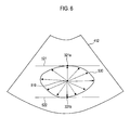
- the contour detecting unit 156 may detect the contours of the parts of interest on the slice images based on the determined seed points. Referring to FIG 6 , the contour detecting unit 156 may set a center point 510 positioned at a center of two seed points 321a and 321b on the slice 412. The contour detecting unit 156 may detect points corresponding to the contour of a part of interest in radial directions with respect to the center point, i.e., edges 530. In one embodiment, the edges 530 of the part of interest may be determined between a line 521 and a line 522, which are defined by two seed points 321a and 321b. The edge detection may be carried out through a conventional method.
- the contour detecting unit 156 may connect the detected edges to each other so that the contour of the part of interest may be set.
- the contour detecting unit 156 may set the contours of the parts of interest for the entire slices 412, 414 and 421-424 through the same process as described above.
- the image processing unit 150 may further include an additional slice processing unit 157.
- the additional slice processing unit 157 may set additional slices between two reference slices 412 and 414.
- the additional slice processing unit 157 may detect the contours of the parts of interest from the additional slices by using linear interpolation.
- the additional slice processing unit 157 may set an additional slice 431 between the slices 412 and 421.
- the additional slice processing unit 157 may detect the contours of the parts of interest on the additional slice 431 by performing linear interpolation upon the contours of the parts of interest on the slice 412 and the contours of the parts of interest on the slice 421.
- the additional slice processing unit 157 may further set additional slices 432-435 in the same manner as described above and then detect the contours of the parts of interest on the additional slices 432-435.
- the ultrasound system 100 may also include a volume measuring unit 160.
- the volume measuring unit 160 may measure an area of the reference part of interest based on the contour of the reference part of interest. Also, the volume measuring unit 160 may measure areas of the parts of interest based on the contours of the parts of interest. In one embodiment, a conventional method of measuring the area with the contour may be adopted. Thus, detailed descriptions of the area measurement will be omitted herein.
- the volume measuring unit 160 may measure a volume of each of the parts of interest based on the area of the reference part of interest and the areas of the parts of interest. In such a case, the measured volume value may be displayed through the display unit 170.
- the volume value may be represented by numeral texts, a bar graph or the like.
- the image processing unit 150 may form 3-dimensional ultrasound images of the parts of interest based on the contour of the reference part of interest on the reference slice image and the contours of the parts of interest on the slice images.
- the image processing unit 150 may apply weights to the 3-dimensional images such that the 3-dimensional images have different transparencies.
- the contours include the contours for setting the parts of interest, which are separate from each other, on the reference plane image as illustrated in FIG 3 , the contours are certainly not limited thereto.
- the contours may include a first contour 361 for separating a first part of interest 351 from the other parts and a second contour 362 for setting a second part of interest 352 within the first part of interest 351.
- the seed points may be automatically and accurately set by using the reference plane image and the slice images. This is so that the contours of the parts of interest on the slice images may be accurately detected.
- the volumes of the specific parts may be accurately measured.
- a plurality of 3-dimensional images of numerous parts of interest may be provided based on the contours of the parts of interest on the reference plane image and the slice images.
Landscapes
- Health & Medical Sciences (AREA)
- Life Sciences & Earth Sciences (AREA)
- Engineering & Computer Science (AREA)
- Physics & Mathematics (AREA)
- General Health & Medical Sciences (AREA)
- Animal Behavior & Ethology (AREA)
- Veterinary Medicine (AREA)
- Radar, Positioning & Navigation (AREA)
- Remote Sensing (AREA)
- Public Health (AREA)
- Surgery (AREA)
- Biophysics (AREA)
- Molecular Biology (AREA)
- Pathology (AREA)
- Medical Informatics (AREA)
- Biomedical Technology (AREA)
- Heart & Thoracic Surgery (AREA)
- Radiology & Medical Imaging (AREA)
- Nuclear Medicine, Radiotherapy & Molecular Imaging (AREA)
- General Physics & Mathematics (AREA)
- Computer Networks & Wireless Communication (AREA)
- Acoustics & Sound (AREA)
- Computer Vision & Pattern Recognition (AREA)
- Theoretical Computer Science (AREA)
- Geometry (AREA)
- Dentistry (AREA)
- Oral & Maxillofacial Surgery (AREA)
- Ultra Sonic Daignosis Equipment (AREA)
Abstract
Description
- The present application claims priority from Korean Patent Application No.
10-2008-0020301 filed on March 5, 2008 - The present disclosure relates to ultrasound systems, and more particularly to volume measurement in an ultrasound system.
- Recently, an ultrasound system has been extensively used in the medical field due to its non-invasive and non-destructive nature. The ultrasound system operates in various image modes such as a brightness mode, a Doppler mode and the like to acquire ultrasound images for diagnosis. Also, the ultrasound system may operate in a measure mode for measuring volumes of parts of interest (e.g., organs, lesions, etc.) contained in a target object. Volume data, which are usually acquired in the brightness mode, may be used to measure the volumes of parts of interest.
- If the measure mode is set, then the ultrasound system allows a user to input a selection instruction for selecting a reference plane from the volume data. Further, a slice setting instruction for setting a plurality of slices, which are perpendicular to the reference plane and parallel to each other, is inputted. The ultrasound system then sets a seed point at a center of each of the slices to extract a contour of the part of interest on each of the slices. The ultrasound system measures the volume of part of interest based on the extracted contours of the part of interest.
- In the conventional ultrasound system, however, only one seed point is set at the center of each slice. As such, an error may occur in extracting the contours of the part of interest on the slices. Thus, the volume of part of interest may be inaccurately calculated. Also, since one seed point is set, a volume for only one part of interest can be measured. That is, when a plurality of parts of interest is contained in the target object, the conventional ultrasound system cannot measure the volumes of parts of interest at the same time.
- Embodiments for measuring volumes of one or more parts of interest are disclosed herein. In one embodiment, by way of non-limiting example, an ultrasound system comprises a volume data forming unit for forming volume data based on ultrasound echoes reflected from a target object, the target object including at least one part of interest; an interface unit for allowing a user to input a selection instruction for selecting a reference plane from the volume data and a slice setting instruction for setting a plurality of slices perpendicular to the reference plane in the volume data; an image processing unit for detecting a contour of the part of interest on the reference plane and determining intersection points of the detected contour and each of the slices as seed points, the image processing unit being further configured to detect contours of the part of interest on the slices based on the seed points; and a volume measuring unit for measuring a volume of part of interest based on the contour on the reference plane and the contours on the slices.
- In another embodiment, a method of measuring a volume of at least one part of interest contained in a target object in an ultrasound system, which includes a volume data forming unit, an interface unit, an image processing unit and a volume measuring unit, comprises the following steps: a) at the volume data forming unit, forming volume data based on ultrasound echoes reflected from a target object containing at least one part of interest; b) at the interface unit, receiving a selection instruction for selecting a reference plane from the volume data; c) at the image processing unit, detecting a contour of the part of interest on the reference plane; d) at the interface unit, receiving a slice setting instruction for setting a plurality of slices perpendicular to the reference plane in the volume data; e) at the image processing unit, determining intersection points of the detected contour and each of the slices as seed points and detecting contours of the part of interest on the slices based on the seed points; and f) at the volume measuring, measuring a volume of the part of interest based on the contour on the reference plane and the contours on the slices.
- The Summary is provided to introduce a selection of concepts in a simplified form that are further described below in the Detailed Description. This Summary is not intended to identify key or essential features of the claimed subject matter, nor is it intended to be used in determining the scope of the claimed subject matter.
-
- FIG 1
- is a block diagram showing an illustrative embodiment of an ultrasound system.
- FIG 2
- is a schematic diagram illustrating volume data.
- FIG 3
- is a schematic diagram showing an example of displaying an ultrasound image of a target object containing a plurality of parts of interest.
- FIG. 4
- is a block diagram showing an illustrative embodiment of an image processing unit.
- FIG 5
- is a schematic diagram showing an example of setting a plurality of slices on a reference plane for determining seed points.
- FIG 6
- is a schematic diagram showing an example of detecting a contour of a part of interest on a slice by using seed points and a center point of the seed points.
- FIG. 7
- is a schematic diagram showing an example wherein one contour encompasses the other contour.
- A detailed description may be provided with reference to the accompanying drawings. One of ordinary skill in the art may realize that the following description is illustrative only and is not in any way limiting. Other embodiments of the present invention may readily suggest themselves to such skilled persons having the benefit of this disclosure.
- Referring to
FIG 1 , an illustrative embodiment of anultrasound system 100 for measuring volumes of parts of interest contained in a target object is shown. As depicted, theultrasound system 100 may include a transmission/reception (Tx/Rx)unit 110. The Tx/Rx unit 110 may be configured to transmit ultrasound signals to a target object and receive ultrasound echoes reflected from the target object. The Tx/Rx unit 110 may be further configured to convert the ultrasound echoes into electrical signals (hereinafter, referred to as "receive signals"). The Tx/Rx unit 110 may include a probe (not shown) containing a plurality of elements for performing reciprocal conversion of ultrasound signals and electrical signals. The Tx/Rx unit 110 may also include a beamformer (not shown) for performing Tx focusing for the ultrasound signals and Rx focusing for the receive signals. - The
ultrasound system 100 may further include a volumedata forming unit 120 that may receive the receive signals from the Tx/Rx unit 110. A volumedata forming unit 120 may form volume data of the target object containing one or more parts of interest (e.g., organs or lesions) based on the receive signals. - The
ultrasound system 100 may further include aninterface unit 130 for allowing a user to input instructions. The instructions may include a selection instruction for selecting a reference plane from the volume data, a contour setting instruction for setting contours of the parts of interest and a slice setting instruction for setting slices on the reference plane. Also, aninterface unit 130 may include a display unit capable of allowing the user to input the instructions while displaying an ultrasound image. In one embodiment, the reference plane, the contours and the slices may be defined as follows: - (1) The reference plane may be one of an A plane, B plane and C plane in the volume
data forming unit 210, as illustrated inFIG 2 . However, the reference plane may not be limited thereto. An arbitrary oblique plane for the A, B or C plane may be also set as the reference plane. - (2) The contours may be used to separate a part of interest desired to measure a volume thereof from the other parts on an image of the reference plane (hereinafter, referred to as "reference plane image"). As illustrated in
FIG. 3 , for example,contours interest other part 324 on thereference plane image 310. - (3) The slices may be set to be perpendicular to the reference plane. For example, assuming that the A plane is set as a reference plane, the slices may be planes parallel with the B plane (including the B plane), or planes parallel with the C plane (including the C plane). Also,
reference slices reference plane 310 in response to the slice setting instruction, as illustrated inFIG. 5 . The number of slices to be set between thereference slices - The
ultrasound system 100 may further include astorage unit 140 that may store the volume data formed in the volumedata forming unit 120. Thestorage unit 140 may further store instructions to implement a contour setting algorithm for automatically setting contours of parts of interest on the ultrasound image. The contour setting algorithm may be implemented based on previously collected contour information of the parts of interest such as human organs. In one embodiment, the contours of the parts of interest on the reference plane image may be automatically set. - The
ultrasound system 100 may also include animage processing unit 150. Theimage processing unit 150 may be configured to form the reference plane image in response to the selection instruction. Theimage processing unit 150 may further operate to detect the contours of the parts of interest on the reference plane image in response to the contour setting instruction. Theimage processing unit 150 may form images of a plurality of slices selected in response to the slice selecting instruction (hereinafter, referred to as "slice images"). Theimage processing unit 150 may set the parts of interest on each of the slice images and determine seed points of the parts of interest based on the previously collected contour information and the slice information. The seed point determination will be described later in detail. Theimage processing unit 150 may be further configured to detect the contours of the parts of interest based on the determined seed points. - The
ultrasound system 100 may further include avolume measuring unit 160. Thevolume measuring unit 160 may be configured to measure volumes of the parts of interest based on the contour detected on the reference plane image and the contours detected on the slice image. - Referring to
FIG 4 , an illustrative embodiment of theimage processing unit 150 is shown. Theimage processing unit 150 may include a referenceplane setting unit 151. The referenceplane setting unit 151 may set the reference plane from the volume data in response to the selection instruction. The referenceplane setting unit 151 may extract data corresponding to the reference plane from the volume data to form the reference plane image. The ultrasound system may also include adisplay unit 170 and the reference plane image may be displayed on thedisplay unit 170. - The
image processing unit 150 may further include acontour setting unit 152. If the contour setting instruction is inputted through aninterface unit 130, then contour setting unit 52 may setcontours interest reference plane image 210, as shown inFIG 3 . On the other hand, if the contour setting instruction is not inputted for a predetermined time period, then thecontour setting unit 152 may set the contours of the parts of interest on thereference plane image 310 based on previously set contour information, which may be previously stored in thestorage unit 140. - The
image processing unit 150 may further include aslice setting unit 153. If the slice setting instruction is inputted through theinterface unit 130, then theslice setting unit 153 may set a plurality of slices on thereference plane image 210. The slice setting instruction may include information upon reference slices and the number of slices to be inserted between first and second reference slices 412 and 414. In one embodiment, theslice setting unit 153 may set first and second reference slices 412 and 414 on thereference plane image 210 based on the reference slice information, as illustrated inFIG. 5 . Theslice setting unit 153 may further set a plurality ofslices first slice 412 and thesecond slice 414 based on the slice number information (e.g., the number of slices = 4). Theslices 421 to 424 may be set at a constant interval between thefirst slice 412 and thesecond slice 414. - The
image processing unit 150 may also include a seedpoint determining unit 154. The seedpoint determining unit 154 may determine seed points on the slice images based on the contours of the parts of interest set on the reference plane image. In one embodiment, the seedpoint determining unit 154 may determine two points where the slices and the contour of each of the parts of interest intersect, as illustrated inFIG 5 . The seedpoint determining unit 154 may set the twopoints interest - The
image processing unit 150 may further include a sliceimage forming unit 155. - The slice
image forming unit 155 may extract data corresponding to the slices from the volume data stored in thestorage unit 140 based on theslices reference plane image 210. The sliceimage forming unit 155 may form slice images corresponding to the slices based on the extracted data. The slice image may be displayed on thedisplay unit 170. - The
image processing unit 150 may also include acontour detecting unit 156. Thecontour detecting unit 156 may detect the contours of the parts of interest on the slice images based on the determined seed points. Referring toFIG 6 , thecontour detecting unit 156 may set acenter point 510 positioned at a center of twoseed points slice 412. Thecontour detecting unit 156 may detect points corresponding to the contour of a part of interest in radial directions with respect to the center point, i.e., edges 530. In one embodiment, theedges 530 of the part of interest may be determined between aline 521 and aline 522, which are defined by twoseed points contour detecting unit 156 may connect the detected edges to each other so that the contour of the part of interest may be set. Thecontour detecting unit 156 may set the contours of the parts of interest for theentire slices - The
image processing unit 150 may further include an additionalslice processing unit 157. The additionalslice processing unit 157 may set additional slices between tworeference slices slice processing unit 157 may detect the contours of the parts of interest from the additional slices by using linear interpolation. In one embodiment, the additionalslice processing unit 157 may set anadditional slice 431 between theslices slice processing unit 157 may detect the contours of the parts of interest on theadditional slice 431 by performing linear interpolation upon the contours of the parts of interest on theslice 412 and the contours of the parts of interest on theslice 421. The additionalslice processing unit 157 may further set additional slices 432-435 in the same manner as described above and then detect the contours of the parts of interest on the additional slices 432-435. Theultrasound system 100 may also include avolume measuring unit 160. Thevolume measuring unit 160 may measure an area of the reference part of interest based on the contour of the reference part of interest. Also, thevolume measuring unit 160 may measure areas of the parts of interest based on the contours of the parts of interest. In one embodiment, a conventional method of measuring the area with the contour may be adopted. Thus, detailed descriptions of the area measurement will be omitted herein. Thevolume measuring unit 160 may measure a volume of each of the parts of interest based on the area of the reference part of interest and the areas of the parts of interest. In such a case, the measured volume value may be displayed through thedisplay unit 170. The volume value may be represented by numeral texts, a bar graph or the like. - In one embodiment, the
image processing unit 150 may form 3-dimensional ultrasound images of the parts of interest based on the contour of the reference part of interest on the reference slice image and the contours of the parts of interest on the slice images. When the 3-dimensional ultrasound images corresponding to the parts of interest are displayed on thedisplay unit 170 at the same time, overlapping portions may occur. Thus, theimage processing unit 150 may apply weights to the 3-dimensional images such that the 3-dimensional images have different transparencies. - Although it is described that the contours include the contours for setting the parts of interest, which are separate from each other, on the reference plane image as illustrated in
FIG 3 , the contours are certainly not limited thereto. As illustrated inFIG 7 , the contours may include afirst contour 361 for separating a first part ofinterest 351 from the other parts and asecond contour 362 for setting a second part ofinterest 352 within the first part ofinterest 351. - As mentioned above, the seed points may be automatically and accurately set by using the reference plane image and the slice images. This is so that the contours of the parts of interest on the slice images may be accurately detected. The volumes of the specific parts may be accurately measured. Also, a plurality of 3-dimensional images of numerous parts of interest may be provided based on the contours of the parts of interest on the reference plane image and the slice images.
- Although embodiments have been described with reference to a number of illustrative embodiments thereof, it should be understood that numerous other modifications and embodiments can be devised by those skilled in the art that will fall within the spirit and scope of the principles of this disclosure. More particularly, numerous variations and modifications are possible in the component parts and/or arrangements of the subject combination arrangement within the scope of the disclosure, the drawings and the appended claims. In addition to variations and modifications in the component parts and/or arrangements, alternative uses will also be apparent to those skilled in the art.
Claims (9)
- An ultrasound system, comprising:a volume data forming unit for forming volume data based on ultrasound echoes reflected from a target object, the target object including at least one part of interest;an interface unit for allowing a user to input a selection instruction for selecting a reference plane from the volume data and a slice setting instruction for setting a plurality of slices perpendicular to the reference plane in the volume data;an image processing unit for detecting a contour of the part of interest on the reference plane and determining intersection points of the detected contour andeach of the slices as seed points, the image processing unit being further configured to detect contours of the part of interest on the slices based on the seed points; anda volume measuring unit for measuring a volume of the part of interest based on the contour on the reference plane and the contours on the slices.
- The ultrasound system of Claim 1, wherein the image processing unit is further configured to form a 3-dimensional image of the part of interest based on the contour on the reference plane and the contours on the slices.
- The ultrasound system of Claim 2, wherein the image processing unit includes:a reference plane setting unit for setting the reference plane in the volume data in response to the selection instruction;a contour setting unit for setting a contour of the part of interest on the reference plane image;a slice setting unit for setting the slices in response to the slice setting instruction;a seed point determining unit for determining intersection points of the contour set on the reference plane and each of the slices as the seed points; anda contour detecting unit for detecting the contours of the part of interest on the slices based on the seed points.
- The ultrasound system of Claim 3, wherein the volume measuring unit is configured to measure an area of the part of interest based on the contour set on the reference plane and an area of the part of interest based on the detected contour on each of the slices, the volume measuring unit being further configured to measure the volume of the part of interest based on the area of the part of interest based on the contour set on the reference plane and the area of the part of interest based on the detected contour on each of the slices.
- The ultrasound system of Claim 3, wherein the seed point detecting unit detects two seed points and wherein the contour detecting unit sets a center point positioned at a center of said two seed points, the contour detecting unit being configured to detect edges in radial directions with respect to the center point and connect the detected edges to form the contour of the part of interest on each of the slices.
- A method of measuring a volume of at least one part of interest contained in a target object in an ultrasound system including a volume data forming unit, an interface unit, an image processing unit and a volume measuring unit, the method comprising:a) forming volume data based on ultrasound echoes reflected from a target object containing at least one part of interest at the volume data forming
unit;b) receiving a selection instruction for selecting a reference plane from the volume data at the interface unit;c) detecting a contour of the part of interest on the reference plane at the image processing unit;d) receiving a slice setting instruction for setting a plurality of slices perpendicular to the reference plane in the volume data at the interface
unit;e) determining intersection points of the detected contour and each of the slices as seed points and detecting contours of the part of interest on the slices based on the seed points at the image processing unit; andf) measuring a volume of the part of interest based on the contour on the reference plane and the contours on the slices at the volume measuring unit. - The method of Claim 6, further comprising forming a 3-dimensional image of the part of interest based on the contour on the reference plane and the contours on the slices at the image processing unit.
- The method of Claim 6, wherein the step e) includes:detecting two intersection points of the contour of the part of interest on the reference plane and each of the slices;setting a center point of two intersection points;detecting edges of the part of interest in radial directions with respect to the center point; andconnecting the edges to detect the contour of the part of interest.
- The method of Claim 6, wherein the step f) includes:measuring an area of the part of interest based on the contour set on the reference plane and an area of the part of interest based on the detected contour on each of the slices; andmeasuring the volume of the part of interest based on the area of the part of interest based on the contour set on the reference plane and the area of the part of interest based on the detected contour on each of the slices.
Applications Claiming Priority (1)
| Application Number | Priority Date | Filing Date | Title |
|---|---|---|---|
| KR1020080020301A KR20090095150A (en) | 2008-03-05 | 2008-03-05 | Ultrasound system and methdo for processing ultrasound image |
Publications (1)
| Publication Number | Publication Date |
|---|---|
| EP2098993A1 true EP2098993A1 (en) | 2009-09-09 |
Family
ID=40524556
Family Applications (1)
| Application Number | Title | Priority Date | Filing Date |
|---|---|---|---|
| EP09002352A Withdrawn EP2098993A1 (en) | 2008-03-05 | 2009-02-19 | Volume measurement in an ultrasound system |
Country Status (4)
| Country | Link |
|---|---|
| US (1) | US20090227869A1 (en) |
| EP (1) | EP2098993A1 (en) |
| JP (1) | JP2009207899A (en) |
| KR (1) | KR20090095150A (en) |
Cited By (2)
| Publication number | Priority date | Publication date | Assignee | Title |
|---|---|---|---|---|
| EP2317472A1 (en) * | 2009-10-13 | 2011-05-04 | Medison Co., Ltd. | An ultrasound system generating an image based on brightness value of data |
| EP2347714A1 (en) * | 2010-01-26 | 2011-07-27 | Medison Co., Ltd. | Performing image process and size measurement upon a three-dimensional ultrasound image in an ultrasound system |
Families Citing this family (10)
| Publication number | Priority date | Publication date | Assignee | Title |
|---|---|---|---|---|
| US9131918B2 (en) * | 2008-12-02 | 2015-09-15 | Samsung Medison Co., Ltd. | 3-dimensional ultrasound image provision using volume slices in an ultrasound system |
| EP2238913A1 (en) | 2009-04-01 | 2010-10-13 | Medison Co., Ltd. | 3-dimensional ultrasound image provision using volume slices in an ultrasound system |
| KR101202533B1 (en) * | 2009-07-30 | 2012-11-16 | 삼성메디슨 주식회사 | Control device, ultrasound system, method and computer readable medium for providing a plurality of slice images |
| KR101117916B1 (en) * | 2009-07-30 | 2012-02-24 | 삼성메디슨 주식회사 | Ultrasound system and method for detecting sagittal view |
| KR101120726B1 (en) * | 2009-08-27 | 2012-04-12 | 삼성메디슨 주식회사 | Ultrasound system and method of providing a plurality of slice plane images |
| KR101067230B1 (en) * | 2009-11-16 | 2011-09-22 | 삼성메디슨 주식회사 | Ultrasound system and method for controlling storage of volume data |
| KR101126891B1 (en) * | 2010-01-12 | 2012-03-20 | 삼성메디슨 주식회사 | Ultrasound system and method for providing slice image |
| KR101117930B1 (en) * | 2010-05-13 | 2012-02-29 | 삼성메디슨 주식회사 | Ultrasound system and method for providing additional information with slice image |
| JP6835587B2 (en) * | 2014-02-19 | 2021-02-24 | コーニンクレッカ フィリップス エヌ ヴェKoninklijke Philips N.V. | Motion-adaptive visualization in medical 4D imaging |
| WO2018231770A1 (en) * | 2017-06-12 | 2018-12-20 | Verathon Inc. | Active contour model using two-dimensional gradient vector for organ boundary detection |
Citations (4)
| Publication number | Priority date | Publication date | Assignee | Title |
|---|---|---|---|---|
| WO1999049775A2 (en) * | 1998-03-30 | 1999-10-07 | Echovision, Inc. | Echocardiography workstation |
| EP0990922A2 (en) * | 1998-09-30 | 2000-04-05 | Matsushita Electric Industrial Co., Ltd. | System for accurately obtaining a contour and/or quantitative information from an echo image with reduced manual operation |
| EP1522875A1 (en) * | 2003-09-30 | 2005-04-13 | Esaote S.p.A. | A method of tracking position and velocity of object's borders in two or three dimensional digital images, particularly in echographic images |
| EP1892671A2 (en) * | 2006-08-23 | 2008-02-27 | Medison Co., Ltd. | System and method for determining the volume of an object by image processing |
-
2008
- 2008-03-05 KR KR1020080020301A patent/KR20090095150A/en not_active Ceased
-
2009
- 2009-02-19 EP EP09002352A patent/EP2098993A1/en not_active Withdrawn
- 2009-03-03 US US12/397,086 patent/US20090227869A1/en not_active Abandoned
- 2009-03-04 JP JP2009051119A patent/JP2009207899A/en active Pending
Patent Citations (4)
| Publication number | Priority date | Publication date | Assignee | Title |
|---|---|---|---|---|
| WO1999049775A2 (en) * | 1998-03-30 | 1999-10-07 | Echovision, Inc. | Echocardiography workstation |
| EP0990922A2 (en) * | 1998-09-30 | 2000-04-05 | Matsushita Electric Industrial Co., Ltd. | System for accurately obtaining a contour and/or quantitative information from an echo image with reduced manual operation |
| EP1522875A1 (en) * | 2003-09-30 | 2005-04-13 | Esaote S.p.A. | A method of tracking position and velocity of object's borders in two or three dimensional digital images, particularly in echographic images |
| EP1892671A2 (en) * | 2006-08-23 | 2008-02-27 | Medison Co., Ltd. | System and method for determining the volume of an object by image processing |
Cited By (3)
| Publication number | Priority date | Publication date | Assignee | Title |
|---|---|---|---|---|
| EP2317472A1 (en) * | 2009-10-13 | 2011-05-04 | Medison Co., Ltd. | An ultrasound system generating an image based on brightness value of data |
| EP2347714A1 (en) * | 2010-01-26 | 2011-07-27 | Medison Co., Ltd. | Performing image process and size measurement upon a three-dimensional ultrasound image in an ultrasound system |
| US8900147B2 (en) | 2010-01-26 | 2014-12-02 | Samsung Medison Co., Ltd. | Performing image process and size measurement upon a three-dimensional ultrasound image in an ultrasound system |
Also Published As
| Publication number | Publication date |
|---|---|
| KR20090095150A (en) | 2009-09-09 |
| US20090227869A1 (en) | 2009-09-10 |
| JP2009207899A (en) | 2009-09-17 |
Similar Documents
| Publication | Publication Date | Title |
|---|---|---|
| US20090227869A1 (en) | Volume Measurement In An Ultrasound System | |
| KR100893286B1 (en) | Image processing system and method | |
| Badano et al. | Use of three-dimensional speckle tracking to assess left ventricular myocardial mechanics: inter-vendor consistency and reproducibility of strain measurements | |
| EP1973076B1 (en) | Ultrasound system and method for forming an ultrasound image | |
| US20140371591A1 (en) | Method for automatically detecting mid-sagittal plane by using ultrasound image and apparatus thereof | |
| KR101175426B1 (en) | Ultrasound system and method for providing three-dimensional ultrasound image | |
| EP2340444A1 (en) | 3-d ultrasound imaging | |
| US9069062B2 (en) | Surface rendering for volume data in an ultrasound system | |
| EP2790588A1 (en) | Automated doppler pulse cycle selection | |
| US11896427B2 (en) | Ultrasonic imaging apparatus and method for detecting shear index of vascular wall using ultrasonic waves | |
| EP2310873B1 (en) | Method of meshing and calculating a volume in an ultrasound imaging system | |
| EP2281509B1 (en) | Setting a Sagittal View in an Ultrasound System | |
| EP2189807A2 (en) | Finding a standard view corresponding to an acquired ultrasound image | |
| KR101014563B1 (en) | Ultrasound system and method for performing vascular segmentation | |
| US20110028842A1 (en) | Providing A Plurality Of Slice Images In An Ultrasound System | |
| US20120108962A1 (en) | Providing a body mark in an ultrasound system | |
| EP2821015A1 (en) | Ultrasound system and method of providing reference image corresponding to ultrasound image | |
| US20080139936A1 (en) | Ultrasound diagnostic system and method of displaying multiple growth trend charts | |
| EP2145580A1 (en) | Recovery function of parameters in an ultrasound system | |
| EP4721672A1 (en) | Elastography method, apparatus and device, and storage medium | |
| EP2380498A1 (en) | Adaptive clutter filtering in an ultrasound system | |
| EP2807977B1 (en) | Ultrasound diagnosis method and aparatus using three-dimensional volume data |
Legal Events
| Date | Code | Title | Description |
|---|---|---|---|
| PUAI | Public reference made under article 153(3) epc to a published international application that has entered the european phase |
Free format text: ORIGINAL CODE: 0009012 |
|
| AK | Designated contracting states |
Kind code of ref document: A1 Designated state(s): AT BE BG CH CY CZ DE DK EE ES FI FR GB GR HR HU IE IS IT LI LT LU LV MC MK MT NL NO PL PT RO SE SI SK TR |
|
| AX | Request for extension of the european patent |
Extension state: AL BA RS |
|
| 17P | Request for examination filed |
Effective date: 20100217 |
|
| 17Q | First examination report despatched |
Effective date: 20100315 |
|
| AKX | Designation fees paid |
Designated state(s): DE FR IT |
|
| STAA | Information on the status of an ep patent application or granted ep patent |
Free format text: STATUS: THE APPLICATION HAS BEEN WITHDRAWN |
|
| 18W | Application withdrawn |
Effective date: 20100708 |