EP2098809A1 - Cooling element with excessive cooling protection - Google Patents
Cooling element with excessive cooling protection Download PDFInfo
- Publication number
- EP2098809A1 EP2098809A1 EP08152376A EP08152376A EP2098809A1 EP 2098809 A1 EP2098809 A1 EP 2098809A1 EP 08152376 A EP08152376 A EP 08152376A EP 08152376 A EP08152376 A EP 08152376A EP 2098809 A1 EP2098809 A1 EP 2098809A1
- Authority
- EP
- European Patent Office
- Prior art keywords
- cooling
- cooling element
- coolant
- fluid
- separating
- Prior art date
- Legal status (The legal status is an assumption and is not a legal conclusion. Google has not performed a legal analysis and makes no representation as to the accuracy of the status listed.)
- Granted
Links
- 238000001816 cooling Methods 0.000 title claims abstract description 217
- 239000002826 coolant Substances 0.000 claims abstract description 162
- 239000012530 fluid Substances 0.000 claims abstract description 93
- 238000003860 storage Methods 0.000 claims abstract description 75
- 238000012546 transfer Methods 0.000 claims abstract description 68
- 230000002776 aggregation Effects 0.000 claims abstract description 36
- 238000004220 aggregation Methods 0.000 claims abstract description 36
- 239000007787 solid Substances 0.000 claims abstract description 33
- 238000000034 method Methods 0.000 claims abstract description 16
- 238000004519 manufacturing process Methods 0.000 claims abstract description 8
- 239000007788 liquid Substances 0.000 claims description 56
- 230000008018 melting Effects 0.000 claims description 29
- 238000002844 melting Methods 0.000 claims description 29
- 239000000463 material Substances 0.000 claims description 19
- 239000004033 plastic Substances 0.000 claims description 18
- 229920003023 plastic Polymers 0.000 claims description 18
- 238000000926 separation method Methods 0.000 claims description 10
- 239000006260 foam Substances 0.000 claims description 9
- XLYOFNOQVPJJNP-UHFFFAOYSA-N water Substances O XLYOFNOQVPJJNP-UHFFFAOYSA-N 0.000 claims description 8
- 239000004793 Polystyrene Substances 0.000 claims description 7
- 238000005192 partition Methods 0.000 claims description 7
- 229920002223 polystyrene Polymers 0.000 claims description 7
- 239000004698 Polyethylene Substances 0.000 claims description 6
- 239000000654 additive Substances 0.000 claims description 6
- 230000002209 hydrophobic effect Effects 0.000 claims description 6
- 239000011148 porous material Substances 0.000 claims description 6
- 238000003780 insertion Methods 0.000 claims description 5
- 230000037431 insertion Effects 0.000 claims description 5
- -1 polyethylene Polymers 0.000 claims description 5
- 239000004952 Polyamide Substances 0.000 claims description 4
- 229920002647 polyamide Polymers 0.000 claims description 4
- 229920000573 polyethylene Polymers 0.000 claims description 4
- LFQSCWFLJHTTHZ-UHFFFAOYSA-N Ethanol Chemical compound CCO LFQSCWFLJHTTHZ-UHFFFAOYSA-N 0.000 claims description 3
- 108010010803 Gelatin Proteins 0.000 claims description 3
- 239000004640 Melamine resin Substances 0.000 claims description 3
- 229920000877 Melamine resin Polymers 0.000 claims description 3
- 229920000159 gelatin Polymers 0.000 claims description 3
- 239000008273 gelatin Substances 0.000 claims description 3
- 235000019322 gelatine Nutrition 0.000 claims description 3
- 235000011852 gelatine desserts Nutrition 0.000 claims description 3
- 239000000203 mixture Substances 0.000 claims description 3
- 235000010987 pectin Nutrition 0.000 claims description 3
- 229920001277 pectin Polymers 0.000 claims description 3
- 239000001814 pectin Substances 0.000 claims description 3
- 229920002451 polyvinyl alcohol Polymers 0.000 claims description 3
- 235000019422 polyvinyl alcohol Nutrition 0.000 claims description 3
- 150000003839 salts Chemical class 0.000 claims description 3
- 239000000758 substrate Substances 0.000 claims description 3
- 230000000996 additive effect Effects 0.000 claims description 2
- 239000002984 plastic foam Substances 0.000 claims description 2
- 230000002441 reversible effect Effects 0.000 claims description 2
- 229920006379 extruded polypropylene Polymers 0.000 claims 1
- 239000012188 paraffin wax Substances 0.000 claims 1
- 239000003814 drug Substances 0.000 abstract description 7
- 239000010410 layer Substances 0.000 description 34
- 238000009413 insulation Methods 0.000 description 17
- 239000004745 nonwoven fabric Substances 0.000 description 15
- 239000012071 phase Substances 0.000 description 13
- 239000000872 buffer Substances 0.000 description 12
- 230000007704 transition Effects 0.000 description 12
- 230000006378 damage Effects 0.000 description 10
- 239000011888 foil Substances 0.000 description 8
- 230000002631 hypothermal effect Effects 0.000 description 7
- 238000004806 packaging method and process Methods 0.000 description 7
- 238000004781 supercooling Methods 0.000 description 7
- 239000007790 solid phase Substances 0.000 description 6
- 239000011810 insulating material Substances 0.000 description 5
- 230000000694 effects Effects 0.000 description 4
- 235000013305 food Nutrition 0.000 description 4
- 230000036961 partial effect Effects 0.000 description 4
- 239000000243 solution Substances 0.000 description 4
- 230000008901 benefit Effects 0.000 description 3
- 230000008859 change Effects 0.000 description 3
- 238000010276 construction Methods 0.000 description 3
- 238000011161 development Methods 0.000 description 3
- 230000018109 developmental process Effects 0.000 description 3
- 229940079593 drug Drugs 0.000 description 3
- 239000004744 fabric Substances 0.000 description 3
- 230000014759 maintenance of location Effects 0.000 description 3
- 239000002356 single layer Substances 0.000 description 3
- 229920001817 Agar Polymers 0.000 description 2
- 241000206672 Gelidium Species 0.000 description 2
- 235000010419 agar Nutrition 0.000 description 2
- 230000003139 buffering effect Effects 0.000 description 2
- 230000006735 deficit Effects 0.000 description 2
- 238000013461 design Methods 0.000 description 2
- 230000008014 freezing Effects 0.000 description 2
- 238000007710 freezing Methods 0.000 description 2
- 230000006870 function Effects 0.000 description 2
- 230000003100 immobilizing effect Effects 0.000 description 2
- 239000012774 insulation material Substances 0.000 description 2
- 238000002955 isolation Methods 0.000 description 2
- 238000005259 measurement Methods 0.000 description 2
- 239000000155 melt Substances 0.000 description 2
- 239000002985 plastic film Substances 0.000 description 2
- 230000008569 process Effects 0.000 description 2
- 125000006850 spacer group Chemical group 0.000 description 2
- 238000003466 welding Methods 0.000 description 2
- 238000009736 wetting Methods 0.000 description 2
- 239000004743 Polypropylene Substances 0.000 description 1
- 239000004372 Polyvinyl alcohol Substances 0.000 description 1
- FAPWRFPIFSIZLT-UHFFFAOYSA-M Sodium chloride Chemical compound [Na+].[Cl-] FAPWRFPIFSIZLT-UHFFFAOYSA-M 0.000 description 1
- 229920006328 Styrofoam Polymers 0.000 description 1
- 238000010521 absorption reaction Methods 0.000 description 1
- 239000002253 acid Substances 0.000 description 1
- 150000007513 acids Chemical class 0.000 description 1
- 230000001476 alcoholic effect Effects 0.000 description 1
- 238000013459 approach Methods 0.000 description 1
- 239000007864 aqueous solution Substances 0.000 description 1
- 230000004888 barrier function Effects 0.000 description 1
- 239000011324 bead Substances 0.000 description 1
- 230000033228 biological regulation Effects 0.000 description 1
- KGBXLFKZBHKPEV-UHFFFAOYSA-N boric acid Chemical compound OB(O)O KGBXLFKZBHKPEV-UHFFFAOYSA-N 0.000 description 1
- 239000004327 boric acid Substances 0.000 description 1
- 235000013532 brandy Nutrition 0.000 description 1
- 239000003795 chemical substances by application Substances 0.000 description 1
- 238000005253 cladding Methods 0.000 description 1
- 230000001427 coherent effect Effects 0.000 description 1
- 238000009833 condensation Methods 0.000 description 1
- 230000005494 condensation Effects 0.000 description 1
- 230000001419 dependent effect Effects 0.000 description 1
- 238000005516 engineering process Methods 0.000 description 1
- 239000003000 extruded plastic Substances 0.000 description 1
- 239000003925 fat Substances 0.000 description 1
- 230000002349 favourable effect Effects 0.000 description 1
- 238000007667 floating Methods 0.000 description 1
- 239000012212 insulator Substances 0.000 description 1
- 230000002427 irreversible effect Effects 0.000 description 1
- 238000005304 joining Methods 0.000 description 1
- 239000007791 liquid phase Substances 0.000 description 1
- 239000005445 natural material Substances 0.000 description 1
- 239000003921 oil Substances 0.000 description 1
- 239000002245 particle Substances 0.000 description 1
- 230000035515 penetration Effects 0.000 description 1
- 230000035699 permeability Effects 0.000 description 1
- 229920006255 plastic film Polymers 0.000 description 1
- 238000006068 polycondensation reaction Methods 0.000 description 1
- 229920001155 polypropylene Polymers 0.000 description 1
- 238000002203 pretreatment Methods 0.000 description 1
- 230000009467 reduction Effects 0.000 description 1
- 239000003507 refrigerant Substances 0.000 description 1
- 230000000717 retained effect Effects 0.000 description 1
- 230000035939 shock Effects 0.000 description 1
- 239000011780 sodium chloride Substances 0.000 description 1
- 238000007711 solidification Methods 0.000 description 1
- 230000008023 solidification Effects 0.000 description 1
- 238000001179 sorption measurement Methods 0.000 description 1
- 239000008261 styrofoam Substances 0.000 description 1
- 239000000126 substance Substances 0.000 description 1
- 230000008961 swelling Effects 0.000 description 1
- 238000012360 testing method Methods 0.000 description 1
- 230000009466 transformation Effects 0.000 description 1
- 235000013311 vegetables Nutrition 0.000 description 1
- 239000000080 wetting agent Substances 0.000 description 1
Images


Classifications
-
- F—MECHANICAL ENGINEERING; LIGHTING; HEATING; WEAPONS; BLASTING
- F25—REFRIGERATION OR COOLING; COMBINED HEATING AND REFRIGERATION SYSTEMS; HEAT PUMP SYSTEMS; MANUFACTURE OR STORAGE OF ICE; LIQUEFACTION SOLIDIFICATION OF GASES
- F25D—REFRIGERATORS; COLD ROOMS; ICE-BOXES; COOLING OR FREEZING APPARATUS NOT OTHERWISE PROVIDED FOR
- F25D3/00—Devices using other cold materials; Devices using cold-storage bodies
- F25D3/02—Devices using other cold materials; Devices using cold-storage bodies using ice, e.g. ice-boxes
- F25D3/06—Movable containers
- F25D3/08—Movable containers portable, i.e. adapted to be carried personally
-
- F—MECHANICAL ENGINEERING; LIGHTING; HEATING; WEAPONS; BLASTING
- F25—REFRIGERATION OR COOLING; COMBINED HEATING AND REFRIGERATION SYSTEMS; HEAT PUMP SYSTEMS; MANUFACTURE OR STORAGE OF ICE; LIQUEFACTION SOLIDIFICATION OF GASES
- F25D—REFRIGERATORS; COLD ROOMS; ICE-BOXES; COOLING OR FREEZING APPARATUS NOT OTHERWISE PROVIDED FOR
- F25D2303/00—Details of devices using other cold materials; Details of devices using cold-storage bodies
- F25D2303/08—Devices using cold storage material, i.e. ice or other freezable liquid
- F25D2303/082—Devices using cold storage material, i.e. ice or other freezable liquid disposed in a cold storage element not forming part of a container for products to be cooled, e.g. ice pack or gel accumulator
-
- F—MECHANICAL ENGINEERING; LIGHTING; HEATING; WEAPONS; BLASTING
- F25—REFRIGERATION OR COOLING; COMBINED HEATING AND REFRIGERATION SYSTEMS; HEAT PUMP SYSTEMS; MANUFACTURE OR STORAGE OF ICE; LIQUEFACTION SOLIDIFICATION OF GASES
- F25D—REFRIGERATORS; COLD ROOMS; ICE-BOXES; COOLING OR FREEZING APPARATUS NOT OTHERWISE PROVIDED FOR
- F25D2600/00—Control issues
- F25D2600/04—Controlling heat transfer
Definitions
- the invention relates to a cooling element for cooling a refrigerated goods and a refrigerated container with a cooling element according to the invention. Furthermore, the invention relates to a method for cooling a refrigerated product using a cooling element according to the invention and to a method for producing a cooling element.
- Such cooling elements, refrigerated containers and methods can be used in particular in the field of pharmacy and medicine for the transport of pharmaceutical and / or medical samples. However, other applications are possible.
- Cooling elements are used in numerous applications and applications. As examples, which are not exhaustive, there are various natural sciences, such as chemistry and biology, as well as medicine and medical technology. Also in pharmacy, for example, such cooling elements are used to store medicines at an optimum temperature and / or to transport. In addition, there are cooling elements, which are used in the household sector or cooling elements for the food industry.
- Such cooling elements usually have a flexible or rigid enclosure into which a cold accumulating liquid (also referred to below as coolant) is introduced. If the cooling element is "charged”, then the cold accumulating liquid is present in the frozen state. This liquid may be present directly in the enclosure or incorporated in a carrier substrate or storage medium. The latter is often used for immobilization and has an advantageous effect on the shape of the cooling element and on a possible cooling time.
- the Cooling element is pre-frozen for a predetermined period of time before use. As a rule, such cooling elements do not have their own active cooling, in particular no power supply.
- a disadvantage of such cooling elements or cooling batteries is that such Vorvorieren or sub-cooling to a temperature below the target temperature of the cooling material usually causes temperatures well below the phase transition between solid state and liquid state of aggregation of the coolant.
- this subcooling of the cooling elements below the ultimately desired target temperature of the goods to be cooled or of the goods it is only possible to maintain the cooling over a longer period of time.
- such a hypothermia of the cooling elements is indispensable in many cases.
- undercooled cooling elements are introduced into a packaging, then, inter alia, in the region of the packaging which contains the goods to be cooled or the goods to be cooled, at first a strong cooling takes place through the undercooled cooling elements.
- refrigerated goods for many types of refrigerated goods, for example in the food industry and / or pharmacy, such hypothermia of the refrigerated goods are associated with partially irreversible damage. Household or food use may cause freezer burn or other damage. In the field of pharmacy or biology, susceptible samples and drugs can become completely unusable due to hypothermia. Therefore, refrigerated goods usually have a target temperature at which should be cooled, a maximum temperature, which should not be exceeded over time, and a tolerance threshold or minimum temperature below the target temperature, within which usually no damage occurs.
- JP 101 11 057 a cooling element, which can be used in particular for vegetables.
- the cooling element has a foam element integrated in a common envelope, which is introduced between the coolant present in closed spaces and the goods to be cooled, in order to protect the refrigerated goods from being supercooled as an insulating element in this way.
- More complex cooling systems are known from the prior art, which should also avoid the above-described problems of an initial supercooling of the goods to be cooled.
- EP 1 477 751 A1 an initial supercooling of the chilled goods by combining a pre-frozen cooling element with a thermal regulation barrier with a liquid which has a temperature above 0 ° C. This additional liquid thus acts as a thermal buffer.
- the disadvantages of this structure are comparable to the disadvantages of the above-described JP 101 11 057 , Again, a complex construction is required with additional handling steps. Furthermore, the total cooling time is again limited by the preheated intermediate element.
- WO 00/12409 describes a cooling package for a sensitive refrigerated goods, in which the refrigerated goods is first wrapped with an inner layer with a volume of water. This inner layer is in turn covered with an outer layer of coolant which is frozen and may have temperatures well below 0 ° C. The supercooled outer layer must first cool the inner water layer until the chilled goods themselves can be cooled. In this way, the inner layer also acts as a thermal buffer which mitigates initial "cold spikes".
- the cooling element should on the one hand reduce or eliminate the known problem of an initial harmful undercooling of temperature-sensitive refrigerated goods, in particular when introducing the refrigerated goods into a transport packaging or during the introduction of pre-frozen cooling elements into the transport packaging.
- the cooling element should, however, be as simple as possible and should at least largely avoid the requirement of additional work steps or additional materials.
- the temperature transitions and temperature conditions within a packaging comprising the cooling elements should be defined as much as possible in order to be able to provide reliable information about the cooling temperature and cooling time of the goods packed therein.
- a "liquid state of aggregation” generally refers to a fluid state of aggregation, that is to say an aggregate state in which the coolant has a low viscosity and high ductility, ie in particular a flowability and / or flowability. Aside from liquid coolants, these can in principle also be coolants in the gaseous state.
- a basic idea of the present invention is that a phase transition between the solid state of aggregation and the liquid state of aggregation is known Boundary conditions always at a known melting point and / or within a known melting range (depending on the nature of the coolant or coolant mixture) saufmdet.
- the invention is based on the recognition that it is possible to spatially separate the solid state of aggregation of the coolant and the liquid state of aggregation of the coolant within a cooling element. Accordingly, for example, a supply of the coolant in the solid state can be cooled down or subcooled almost as long as it is sufficiently thermally separated and / or isolated from the material to be cooled.
- the liquid state of aggregation of the cooling medium which has a temperature of at least the temperature of the melting point and / or melting range, can be made possible by suitable devices to come into closer thermal contact with the goods to be cooled and thus as a heat transfer medium between the goods to be cooled and the solid state of aggregation to act of the coolant.
- a cooling element which can be used for cooling a refrigerated goods.
- the refrigerated goods can, for example, as shown above, be taken from the field of natural sciences, medicine, pharmacy, food industry or household.
- the item to be cooled may comprise thermally sensitive item to be cooled, which should not be cooled below a certain minimum temperature and / or below a tolerance threshold below a target temperature.
- the cooling element comprises an envelope, which may be configured in particular as a closed envelope.
- This enclosure may include a flexible and / or rigid enclosure, as further detailed below.
- Particularly suitable as materials for such sheaths are plastics, in particular plastic films or plastic sheets. Due to their low permeability in particular mixed plastics of polyethylene and polyamide have proven to be advantageous.
- the envelope can also be designed in several layers and can be designed differently, for example, in different areas of the cooling element, for example, to allow anisotropic different heat transfer in different areas of the enclosure.
- the envelope in particular has at least one heat transfer wall for exchanging thermal energy with the refrigerated goods.
- the enclosure may have exactly one heat transfer wall, for example a planar heat transfer wall.
- this heat transfer wall may be one or more sides of a film wrapping, for example a film bag.
- the term "for exchanging thermal energy with the refrigerated goods" is not necessarily to be understood as a direct thermal contact with the refrigerated goods, so that, for example, in addition to a direct contact with the refrigerated goods, an interposition of other thermally insulating elements, such as foam - Or Styrofoam elements, and / or air or gas layers may be possible.
- the cooling element has at least one fluid space adjoining the heat transfer wall and at least one storage space separated from the fluid space.
- the fluid space and the storage space are separated by at least one separating element.
- the term "separation” here refers to a mechanical retention of the solid phase of the coolant (see the description below) and at least largely keeping this solid phase away from the fluid space.
- the separation as explained below, additionally also relates to a thermal separation, that is to say an at least partial thermal insulation.
- a solid state of aggregation is also understood to mean a viscous state of a coolant in which the viscosity of the coolant is so high that the coolant in this viscous state can not flow into the fluid space separated by at least one separating element.
- a liquid state of aggregation is also understood to mean a liquid state of a coolant in which the viscosity of the coolant is correspondingly low, so that the coolant in this liquid state can flow into the fluid space separated by at least one separating element.
- coolants may be, for example, paraffins or wax-like substances.
- the storage space is set up to receive a coolant supply in a fixed state of aggregation.
- this may be one or more solid blocks of the coolant, which may assume a virtually random geometric shape.
- the storage space can additionally have at least one storage element for receiving the coolant supply, although this is not absolutely necessary.
- the separator is configured to substantially keep the coolant supply in the solid state from the fluid space substantially.
- substantially in this context is meant that the fluid space should preferably not have more than 5%, preferably not more than 1% of the refrigerant in the frozen state.
- the cooling element can be constructed comparatively simple, in contrast, for example, to the complex multi-chamber systems of JP 101 11 057 or the WO 00/12409 .
- the handling of the cooling element, which may be formed as a single cooling element is extremely simple, since this can be overcooled as a whole, in contrast to the separate pretreatments of in WO 00/12409 and EP 1 477 751 A1 described multi-part structures.
- the cooling element according to the invention can be further developed in various ways advantageous. These optional developments can be implemented individually or in combination.
- the cooling element in the storage space at least one storage element having, which is adapted to receive the coolant supply in whole or in part and at least partially immobilize.
- the cooling element in the storage space at least one storage element having, which is adapted to receive the coolant supply in whole or in part and at least partially immobilize.
- the storage element can absorb the coolant supply mechanically, by adsorption and / or by absorption.
- the storage element may comprise at least one sponge-like element, that is, an element having a plurality of pores for receiving the coolant supply.
- the sponge-like element may comprise a material which is well suited, for example, for its surface properties for receiving the coolant.
- the storage element may also comprise a foam substrate, a plastic foam, in particular a melamine resin foam, a superabsorber, a swelling agent or similar materials.
- the storage element may also comprise further additives, for example wetting agents for better filling of the storage element with the coolant.
- the storage element may also comprise at least one immobilization medium, which is set up to thicken the coolant and in this way reduce the mobility of the coolant.
- immobilization medium for example, gelatin, agar agar, pectin, polyvinyl alcohol or the like may be used as the immobilizing medium.
- the coolant supply may be wholly or partially received in the storage element.
- the storage element may then be arranged to receive only the fixed coolant supply, whereas the coolant in the liquid state of aggregation should be allowed to circulate to the fluid space.
- the storage element for example, have different retention properties for the coolant in the solid and liquid state of aggregation, so that, for example, coolant, which has passed into the liquid state of aggregation, more easily detached from the storage element.
- surface properties of the storage element can be set specifically.
- changes in volume during the phase transition can also be used.
- the coolant supply can be dimensioned such that it completely saturates the storage element in the liquid state.
- the at least one storage space and the at least one fluid space can communicate with one another through at least one fluid channel.
- This at least one fluid channel can be designed in various ways and should be dimensioned such that this at least larger pieces of coolant in the frozen state, that is, in a solid state, denied the passage into the fluid space.
- the fluid channel can be wholly or partially configured in the at least one separating element.
- the fluid channel can pass through the separating element in the form of at least one bore and / or at least one opening.
- a plurality of holes and / or openings is conceivable, for example in the form of a sieve.
- a porous separating element is also conceivable, in which case the pores should be configured such that they allow passage of the liquid coolant.
- the at least one fluid channel can also be formed, for example, by a combination of the separating element and the casing and / or an additional component.
- the fluid channel can be formed between the separating element and the envelope.
- separating webs may be provided for this purpose, for example, which are formed between the separating element and the casing. These partitions may be wholly or partly, for example, part of the separating element and / or may be part of the enclosure and / or may be at least partially formed as an independent component.
- the enclosure may be oversized, so that a circulation of the separating element is made possible by the liquid coolant.
- dividers are particularly suitable for rigid sheaths, but is also possible with flexible sheaths.
- the partitions act in this case, for example, as a spacer on the inside of the enclosure.
- the separating element may in particular, alone or in cooperation with the enclosure, form the at least one fluid channel.
- the separating element may, for example, at least one sheet-shaped, plate-shaped or disc-shaped separating element include, in general, an element whose lateral dimensions exceed its thickness by a multiple.
- at least one fluid channel designed as a fluid gap should be formed between the separating element and the casing for exchanging fluid coolant between the storage space and the fluid space. The coolant can thus reach the fluid space by flowing around the sheet, plate or disc-shaped separating element in liquid state of aggregation.
- the separating element may comprise a plurality of stacked, plate-shaped or disk-shaped separating elements stacked on one another.
- this plurality of such separators may require multiple recirculation until the liquid coolant enters the fluid space.
- a labyrinth structure or a labyrinth-like structure can be created and used as a separating element or as part of the separating element.
- a further advantage of using a plurality of individual separating elements is that, by varying the number and / or the thermal properties of the individual separating elements, the thermal properties, in particular the thermally insulating properties such as thermal conductivity or thermal resistance, of the entire separating element structure in a simple manner can be adapted to different requirements, for example by varying the number of layers of individual separating elements.
- the separating element can in particular be made mechanically flexible.
- the separating element may comprise a nonwoven fabric, ie a nonwoven or non-knitted or knitted fabric, in particular a nonwoven plastic material.
- the plastic nonwoven fabric may be a plastic nonwoven fabric of extruded material having short chain and long chain portions and an amorphous structure.
- Nonwovens, in particular porous nonwovens have proved to be good thermal insulators and can at the same time be optimally adapted to the required properties (for example low wetting and / or uptake of the coolant).
- the cooling element may comprise one or more layers of a flexible insulation layer, for example a flexible nonwoven.
- extruded thermally insulating plastics in particular polyethylenes, polystyrenes, polypropylenes, polyamides or other plastics or mixed plastics can be used.
- extruded plastics for example, in turn plastic nonwovens, have particularly favorable properties on the one hand because they are thermally insulating and on the other hand have a low proportion of air pockets, which could reduce the basic effect of the invention described above.
- the at least one separating element may also comprise one or more insulating elements, for example one or more evacuated carrier plates or insulating elements with gaseous insulating media.
- the insulating performance of the separating element that is to say the thermal insulation of the storage space relative to the fluid space and / or to the cooling medium, can be influenced within wide ranges. For example, this can be done easily by the use of insulating webs by the choice of the number of layers of the nonwoven fabric.
- the separating element may in particular have thermally insulating properties in order to reduce or restrict an immediate heat transfer from the coolant in a fixed state of aggregation in the storage space to the refrigerated goods. Accordingly, it is particularly preferred if the separating element has a thermal conductivity of 0.01 W / (m * K) to 0.5 W / (m * K), particularly preferably in the range of 0.035 W / (m * K).
- the separating element may contain one or more corresponding insulating materials which, alone or in combination, cause said thermal conductivities.
- the separating element has a thermal resistance of at least 0.05 m 2 K / W.
- one or more appropriate insulation materials and / or isolation media such as gas-filled and / or evacuated plates) may be provided, which cause the properties mentioned alone or in combination.
- a further preferred embodiment of the invention is that the separating element should absorb the smallest possible proportion of the coolant in the liquid and / or solid state.
- This further development has the advantage that the separating element does not or only to a very small extent absorbs cooling agent in the solid state during subcooling, which could then come into closer thermal contact with the refrigerated goods.
- many cooling elements are stored at room temperature, only to be subcooled before use. Had the separator a large capacity for the liquid coolant, so this would be soaked before subcooling, for example, already with coolant, which would then freeze within this separator.
- the separating element is such is configured that this can accommodate a coolant content of at most 1%, preferably even less, for example, a maximum of 0.2%.
- the coolant may be a polar coolant or at least have a polar coolant component, wherein the separator in this case preferably has at least partially hydrophobic properties.
- water can be used as the coolant, for example in combination with a hydrophobic nonwoven as the separating element, so that a low uptake of coolant in the nonwoven fabric is ensured.
- the separating element has hydrophilic properties at least in sections.
- the coolant can be designed in various ways and, in particular, can be adapted to the goods to be cooled, as described below.
- the coolant should be a material having a suitable melting point and / or melting range, which is preferably adapted to receive latent heat upon melting. It is possible to use individual coolants or even coolant mixtures. In particular, the melting point and / or the melting range can be adjusted in a wide range of optimum temperatures of the refrigerated goods.
- the coolant may in particular comprise water or alcohol as a polar component. Alternatively or additionally, the coolant may also comprise non-polar components, for example oils, fats, paraffins or similar non-polar liquids. While polar liquids are used in particular in the range up to 0 ° C, non-polar liquids can be used for example as a coolant in the range of positive temperatures, in particular in the range of positive temperatures below room temperature.
- the coolant can be influenced by one or more additives in its properties.
- the melting point or melting range can in turn be adjusted by suitable selection and / or concentration of such additives, as well as other properties such as viscosity, polarity, wetting power or the like.
- at least one salt and / or at least one sugar can be used as an additive.
- sol-containing aqueous solutions can be used, ie salt-water solutions, for example saline solutions.
- a "space” in this context is generally to be understood as meaning at least one lumen which can receive liquid coolant. Several contiguous or separate lumens are possible.
- the fluid space which adjoins the at least one heat transfer wall directly or with the interposition of additional thermally insulating elements, can be designed in various ways.
- the fluid space can be arranged wholly or partly between the separating element and the heat transfer wall.
- usually a fluid space of extremely small thickness is sufficient, for example, only a small gap between the separating element and the heat transfer wall.
- the use of narrow dimensions for the fluid space and / or the fluid channel also offers the advantage that capillary forces can be utilized to move liquid coolant from the storage space into the fluid space.
- the fluid space between the separating element and the heat transfer wall may also be wholly or partly contained in the separating element.
- the separating element may have a porous volume and / or grooves, depressions, bores or the like. Other embodiments are possible.
- this enclosure may be designed, for example, rigid or flexible and may comprise, for example, a film wrapping.
- the envelope can also be designed in several layers.
- the sheath may in particular comprise at least one insulating element which at least partially prevents and / or slows down a heat transfer via at least one wall of the sheath.
- thermally insulating plastic materials and / or natural material materials can be used, which are known to prevent heat transfer.
- foams, other types of porous materials or nonwovens may be used for this purpose again.
- fabric materials or knitted fabrics can be used.
- these insulating elements are arranged in a region of the envelope, which is different from the heat transfer wall.
- the storage space can be thermally insulated and / or shielded from the environment in this way, for example on the sides which are not the separating element or the fluid space to assign. In this way, it is ensured that a heat input into the coolant contained in the storage space can preferably take place exclusively or predominantly via the liquid coolant from the fluid space.
- the heat transfer wall can also comprise a lower degree of such a thermal insulation or an insulating element, so that the heat transfer through this heat transfer wall is at least slowed down.
- a coolant can be selected, with a melting point or a melting range at the bottom of the tolerance range of the refrigerated goods or even below this tolerance range, without damaging the refrigerated goods must be feared by hypothermia.
- the inventive principle can be combined with the traditional principles of the thermal buffer.
- This thermal buffer or the insulating element in addition to pure passive insulating materials, accordingly naturally also include more complex insulating media, such as liquids, as in the WO 00/12409 and / or the EP 1 477 751 A1 shown.
- the at least one insulating element can abut directly against the casing, in particular at least in partial areas, so that no further fluid space is formed between the insulating element and the casing, in particular not in the areas of the casing which are not directly facing the refrigerated goods.
- the envelope has a film or is designed as a film envelope.
- mixed plastics have proven to be advantageous, in particular mixed plastics with at least a proportion of polyethylene and at least a proportion of polyamide (PE / PA plastics).
- Such mixed plastics have a particularly low penetration capacity for conventional coolants, in particular for aqueous coolants. In this way, even with a stacking of the cooling elements when subcooling a sticking together of the cooling elements, for example, by freezing "condensation" can be avoided.
- the thickness of the film or the cladding may, for example, be in the range of a few tens to a few hundred micrometers, for example 50 micrometers.
- the enclosure may further comprise at least one mark for identifying the heat transfer wall.
- markings may include, for example, imprints which facilitate positioning or orientation of the cooling elements, so that it can be ensured that the heat transfer wall and not the remaining walls are always allocated to the goods to be cooled.
- the wrapper also have an asymmetrical outer shape (for example in the form of lugs, beads, ridges, grooves or the like), which makes a reversed insertion of the cooling element in a refrigerated container at least recognizable and / or at least partially prevented.
- This asymmetric shape can be realized, for example, in welded foil bags or foil pockets by an asymmetrically extending weld.
- the enclosure may in particular comprise at least one recessed bottom part, in particular a foil bag.
- This film bag can be produced, for example, by a film-deep-drawing process.
- the enclosure may comprise at least one lid part welded to the bottom part. Instead of welding, however, other types of connection techniques of positive, cohesive or non-positive nature are possible.
- the heat transfer wall may in particular be formed either in the cover part and / or in a bottom surface of the bottom part opposite the cover part. In particular, it is preferred if the surface which forms the heat transfer wall completely or partially is configured as flat as possible. A more complex configuration is also possible, for example with an internal storage space and with one or more fluid spaces arranged on the outside.
- a refrigerated container for cooling a refrigerated product is also proposed.
- the refrigerated container can in particular be completely or partially closed and can be designed, for example, to receive one or more of the refrigerated goods described above.
- the refrigerated container can be configured as a transportable refrigerated container, in particular as a transport box.
- the refrigerated container may include, for example, wheels and / or handles and / or other types of transport devices which facilitate transport of the refrigerated container.
- the refrigerated container comprises at least one thermally insulating outer container.
- This outer container may for example be configured in one or more layers and may in particular comprise one or more thermally insulating materials. For example, these may again be porous plastics, foams or similar insulating materials. Also a multi-layer construction is possible.
- the refrigerated container comprises at least one cooling element according to one or more of the embodiments described above. In this case, the cooling element is arranged in the outer container such that the heat transfer wall assigns the refrigerated goods.
- the outer container may have at least one receptacle for the spatial fixing of the cooling element.
- This receptacle may include, for example, one or more slots, in which the at least one cooling element can be inserted.
- other types of fixing devices are possible, such as bolts, flaps or other positive or non-positive connections. The fixation should in this case take place in such a way that when the cooling element accommodated in the receptacle assigns the heat transfer wall of the cooling element to the refrigerated goods.
- the refrigerated container and / or the receptacle can in particular also be designed such that all outer surfaces of the envelope of the cooling element, with the exception of the heat transfer wall, are separated from the refrigerated goods.
- at least one cover may be provided, which covers the side walls of the cooling element, so that only one of the heat transfer wall-containing front side of the cooling element assigns the refrigerated goods.
- a recording is possible such that a plurality of cooling elements mutually shield their edges against the refrigerated goods, so that only the heat transfer walls with the refrigerated goods in thermal contact (directly or indirectly) are.
- the refrigerated container can have at least one inner container arranged between the cooling element and the refrigerated goods.
- This inner container may, for example, have certain mechanical properties which, for example, cause a mechanical separation of the refrigerated goods from the cooling element, so that, for example, the refrigerated goods do not damage the cooling elements.
- a transport or insertion of the refrigerated goods in the refrigerated container by means of the inner container is possible.
- the inner container may also have thermally insulating properties, in order to create an additional "passive" buffer layer (naturally also several buffer layers can be provided) between the at least one cooling element and the refrigerated goods.
- a method for cooling a refrigerated product using at least one cooling element is also proposed.
- a cooling element is used according to one or more of the embodiments described above, so that reference can be made to the above description for details of the cooling element.
- the cooling element is selected such that it has at least one coolant with a melting point and / or a melting range below a target temperature for the cooling of the cooling material.
- this melting point and / or the melting range should be within a predetermined tolerance range below the target temperature, with an area above a minimum temperature of the term "tolerance range" should be included.
- this tolerance range can be predetermined by the item to be cooled, in that this tolerance range designates, for example, the range within which no damage to the item to be cooled can occur due to hypothermia.
- the tolerance range can be 1-15 Kelvin, more preferably about 1-5 Kelvin.
- the tolerance range can, however, be extended further downwards.
- the cooling element may have a temperature below the tolerance range, which, however, may be thermally separated by one or more additional insulating elements, which may for example be integrated into the cooling element and / or mounted separately from the cooling element between the cooling element and the cooling material. In this way it can be ensured that no damage to the chilled goods occurs.
- the cooling element is first subcooled to a subcooling temperature below the target temperature and in particular below the tolerance range.
- the coolant supply introduced into the storage space is brought into the solid state of aggregation and cooled to the subcooling temperature.
- the cooling element is brought directly or indirectly with its heat transfer wall in thermal contact with the refrigerated goods.
- directly or indirectly can be understood that the heat transfer wall is directly connected to the refrigerated goods and / or that one or more intermediate layers between the heat transfer wall and the refrigerated goods are introduced, for example, vessel walls, packaging, air or gas layers, thermally insulating Layers or similar.
- the pre-frozen cooling element thus initially contains the coolant in the storage space at a subcooling temperature, which is preferably far below the phase transition temperature. Since the coolant can not yet penetrate into the fluid space, the frozen coolant is still separated from the material to be cooled at least by the separating element, the fluid space and the heat transfer wall. There is thus only an extremely low heat transfer. This is particularly favored by the fact that the at least a separating element additionally has thermally insulating properties, such as by using the above-described nonwovens with thermally insulating properties. It is thus avoided a direct thermal contact between the solid, supercooled phase of the coolant with the product side facing the envelope, so that there are no harmful low temperatures at the onset of the cooling element on this page.
- the solid phase of the coolant melts from the outside by heat input, so that now liquid coolant is present at the same time with the solid phase.
- This liquid coolant which has temperatures at or just above the melting temperature or the phase transition temperature, can now flow into the fluid space facing the refrigerated goods between the separating element and the casing or the heat transfer wall and tempered this fluid space or the heat transfer wall accordingly. In this way, a targeted and defined temperature control of the refrigerated goods at or just above the phase transition temperature over a long period of time, until the solid phase of the coolant is completely melted in the storage space.
- the melting range is in a range between -18 ° C and 0 ° C.
- the supercooling temperature is preferably below this melting point or melting range, for example in a range between -18 ° C and -20 ° C.
- the cooling element may be a cooling element according to a plurality of the embodiments described above, so that reference may be made to the above description for possible details and possible embodiments of this cooling element.
- the proposed manufacturing process comprises the following process steps. However, these steps do not necessarily have to be performed in the order shown. Furthermore, one or more of the method steps can also be carried out in parallel or repeatedly in time.
- At least a bottom part of a sheath of the cooling element is produced.
- it may, as stated above, at this bottom part to act on a foil bag, so for example a pot-shaped or bowl-shaped bag with one or more wells.
- a film deep drawing process can be used for this production.
- At least one coolant supply is introduced into the bottom part.
- the coolant can basically be introduced alone in the bottom part.
- a storage element can be introduced into the bottom part, which is completely or partially filled with the coolant prior to introduction or after introduction.
- the storage element can be set up to completely or partially receive and at least partially immobilize the coolant supply.
- the coolant supply is preferably dimensioned such that it is substantially completely absorbable in the liquid state in the storage element.
- “Substantially complete” may also be understood to mean a slight excess or deficit, for example an excess or deficit of not more than 5%. With respect to possible embodiments of the memory element, reference may be made to the above description.
- immobilization can be used.
- another immobilization medium can be used, which is set up to thicken the coolant and thus reduce the mobility of the coolant.
- gelatin, agar agar, pectin or the like may be used as the immobilizing medium.
- At least one separating element is introduced into the bottom part, which is designed to subdivide an interior space of the enclosure into a coolant reservoir receiving storage space and a fluid space, wherein the separating element is arranged to substantially keep the coolant supply in a fixed state of aggregation of the fluid space and coolant in the liquid state of aggregation to allow the passage from the storage space into the fluid space.
- a cover part is applied to the bottom part and connected to the bottom part.
- this cover part may in turn comprise a foil lid or be a foil lid.
- Suitable connection techniques with the bottom part are in principle suitable form and / or force and / or cohesive joining techniques. Particularly preferred is a Welding the lid part with the bottom part, for example, along a weld.
- the at least one heat transfer wall may be formed either in the cover part or in the bottom part. Accordingly, the order of introduction of the coolant supply and / or of the optional storage element and of the separating element may also change in relation to the sequence described above. If, for example, a heat transfer wall is provided in the bottom part, then for example the dividing element can first be introduced, and then the storage element and / or the coolant supply. If, on the other hand, the heat transfer wall is provided in the cover part, then preferably the sequence given above can be used.
- coolants can be used, which can be adapted in particular to the goods to be cooled from the melting point or melting range. It is particularly preferred, as also stated above, if a coolant is used which has a lower density in the solid state of aggregation than in the liquid state of aggregation.
- the change in volume then associated with the change in the state of aggregation, that is to say the phase transition, can drive or promote the circulation of the liquid coolant through the fluid space.
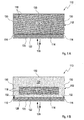
- FIGS. 1 and 2 a first embodiment of a cooling element 110 according to the invention is shown in a highly schematic sectional view from the side.
- the cooling element 110 comprises a sheath 112, which is merely indicated in the figures.
- it may be a foil wrapping.
- This separating element 114 may, for example, comprise one or more layers of a hydrophobic plastic fleece, for example a fleece of polystyrene, similar to nonwovens, which are used, for example, in impact sound insulation for floors.
- the separator 114 is intended to have thermal insulation properties.
- the separating element 114 is undersized in such a way in comparison to the sheath 112 that a fluid channel 116 in the form of a gap is formed on the side edges of the separating element 114 between the separating element 114 and the sheath 112.
- the partition 114 is preferably not fixedly connected to the enclosure 112 here and in other embodiments, but is formed as a "floating" partition 114 inside this enclosure 112, which also facilitates the manufacture of the cooling element 110 in particular.
- the separating element 114 subdivides the interior of the envelope 112 of the cooling element 110 into a storage space 118 and a considerably smaller sized fluid space 120 compared to the storage space 118.
- the fluid space 120 is formed only as a thin gap between the separating element 114 and a heat transfer wall 122 of the envelope 112 ,
- the heat transfer wall 122 is at the in the Figures 1A and 1B However, other embodiments are possible, as described in more detail below.
- a coolant 124, 126 is introduced into the storage space 118.
- Figure 1A shows a state in which the coolant is completely in the solid state, which is designated in the figures by the reference numeral 124.
- a supercooled state may be in which the cooling element 110 is overcooled to a temperature well below a phase transition temperature (melting temperature) of the coolant 124, 126.
- the coolant 124, 126 is preferably completely accommodated in the storage space 118 in this supercooled state.
- the fluid space 122 is preferably completely free of coolant 124, 126.
- cooling element 110 is brought with a refrigerated goods, which is not shown in the figures, in direct or indirect thermal contact, so that on the heat transfer wall 122, a heat exchange is possible, which is symbolically denoted by the reference numeral 128 in the figures.
- the remaining side walls, which are designated 130 in the figures are additionally thermally insulated so that the heat exchange takes place almost completely via the heat transfer wall 122.
- the coolant 124, 126 begins to melt, which generally takes place from the edge.
- the block of the solid coolant 124 melts, and liquid coolant 126 initially forms in the storage space 118.
- this liquid coolant may be an aqueous coolant and / or an alcoholic coolant, optionally with the addition of additives, such as, for example, salts. to set a melting point.
- the separating element 114 absorbs practically no coolant 126.
- the liquid coolant 126 therefore flows through the fluid channel 116, the separating element 114.
- FIG. 1B symbolically denoted by the reference numeral 132.
- the liquid coolant 126 occurs in the Fluid space 120 and can via the heat transfer wall 122 in thermal contact with the goods to be cooled, so that a heat exchange 128 can take place.
- the embodiment of the cooling element 110 according to FIG. 2 differs from the embodiment according to Figure 1A in that, as above to the Figures 1A and 1B already mentioned, the remaining walls 130 of the enclosure 112, that is, the walls other than the heat transfer wall 122, are additionally thermally shielded by insulating elements 134.
- These insulating members 134 which preferably closely abut the sheath 112 and / or are part of this sheath 112 so that no additional fluid space 120 can form between these sheath members 134 and the sheath 112, prevent or reduce heat exchange through these remaining walls 130.
- the heat exchange 128 with the environment or the refrigerated goods thus takes place almost exclusively via the heat transfer wall 122.
- FIG. 3 is a highly simplified embodiment of a refrigerated container 136 shown in section from above.
- the refrigerated container 136 comprises in this embodiment a thermally insulated outer container 138, which thermally shields a heat input from the outside.
- the outer container 138 may comprise a foam and / or a polystyrene.
- FIG. 3 shows the cooling elements 110 inside the outer container 138 inside the outer container 138 .
- four cooling elements 110 arranged inside the outer container 138 .
- FIG 3 shows the cooling elements 110 according to the in FIG. 2 used embodiment shown.
- other embodiments of inventive cooling elements 110 are possible.
- the orientation of the cooling elements 110 in the interior of the refrigerated container 136 takes place in such a way that the heat transfer walls 122 of the cooling elements 110 always point into the interior of the refrigerated container 136, that is to say in the interior of the refrigerated container 136 FIG. 3 only indicated refrigerated goods 140.
- the remaining walls 130 of the cooling elements 110 preferably have completely either the outer container 138 or an adjacent cooling element 110, so are compared to the refrigerated goods 140 and the interior of the refrigerated container 136 shielded.
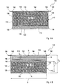
- cooling elements 110 are shown schematically in a sectional view from the side. These cooling elements 110 correspond structurally largely to the structure of the cooling element 110 in the FIGS. 1A, 1B or 2 and have a sheath 112.
- this envelope 112 is configured in two parts and has a recessed bottom part 142 and a cover part 144. Both parts 142, 144 may for example be made of a PA / PE film, for example with a film thickness of 100 to 500 microns.
- the sheath 112, analogous to FIG. 2 nor one or more insulating elements 134, which in the FIGS. 4A and 4B are not shown.
- the bottom part 142 may be formed for example as a deep-drawn film pocket.
- the cover part 144 and the bottom part 142 may, for example, be connected to one another along a weld seam 146, for example a circumferential weld seam.
- the cooling element 110 comprises in the in the FIGS. 4A and 4B shown embodiment, a storage element 148 which, for example, in the in the FIGS. 4A and 4B shown supercooled state, the coolant 124 can almost completely absorb.
- This storage element 148 may, for example, be designed as a sponge-like element, that is to say as a porous element with a high capacity for holding the liquid or solid coolant 124, 126.
- a foamed melamine resin may be used for this purpose.
- the storage element 148 preferably fills the storage space 118 substantially completely.
- the storage element 148 can be introduced into the storage space 118 as a rectangular block or as a block with a circular cross section.
- the separating element 114 adjoins the storage space 118.
- this separating element 114 reference may be made to the above description.
- a fluid channel 116 may be formed between the separating element 114, which may be configured, for example, as a single-layer or multi-layer hydrophobic nonwoven fabric, and the sheath 112 between the separating element 114, which may be configured, for example, as a single-layer or multi-layer hydrophobic nonwoven fabric, and the sheath 112
- a fluid channel 116 may be formed between the separating element 114, which may be configured, for example, as a single-layer or multi-layer hydrophobic nonwoven fabric, and the sheath 112
- the fluid channel 116 can also be configured in other ways, for example in the form of bores, through-going pores, a sieve, spacers or the like passing through the separating element 114.
- the separating element 114 is shown symbolically as a single-layer separating element 114, for example as a single layer of a nonwoven.
- FIG. 4B In contrast, a preferred embodiment is shown, in which the separating element 114 comprises four individual layers of a nonwoven, for example polystyrene nonwovens with a thickness of approximately 1 to 3 mm, for example 2 mm.
- the multilayer configuration can also in the embodiment in FIG. 4A or other embodiments may be used.
- the embodiments in the FIGS. 4A and 4B differ substantially by the orientation of the heat transfer wall 122. While in the embodiment in FIG. 4A the heat transfer wall is part of the bottom part 142 and the cover part 144 is arranged opposite, is in the embodiment in FIG. 4B the heat transfer wall 122, the lid part 144 and part of this cover part 144. In function, these different configurations differ only slightly. However, since the film projections 150 are used in many cases as a positioning aid, as below with reference to FIG. 5 is explained in more detail, this different configuration may be of practical importance to facilitate a correct alignment of the heat transfer wall 122 to the chilled goods 140. In addition, the enclosure 112 may be wholly or partially printed to additionally identify, for example, the heat transfer wall 122 and to prevent improper insertion of the cooling elements 110 into a refrigerated container 136.
- cooling element 110 In FIG. 4B symbolically different dimensions of the cooling element 110 and the components of this cooling element are shown. These dimensions can vary greatly depending on the field of application.
- cooling elements were produced, which have a width b between 170 mm and 210 mm, for example, a rectangular base with an edge length of 210 mm x 170 mm.
- the height h 1 of the memory element 148 can also vary widely and can be, for example, about 40 mm.
- the total height h 2 can also vary and can be, for example, 50 mm.
- a polystyrene nonwoven having a thickness of 2.2 mm have proved to be advantageous.
- other thicknesses are used, for example, thicknesses of 3 mm or 5 mm.
- polystyrene fleece of the brand "SELITAC” SELIT Dämmtechnik GmbH, Erbes-Büdesheim, Germany were used, which are also used for the purpose of impact sound insulation in floors.
- Such nonwovens have a thermal conductivity of between 0.026 W / mK (effectively measured according to DIN 52612) and 0.35 W / mK (classification according to the heat conduction group according to DIN 4108).
- a thermal resistance of 0.34 m 2 K / W for the entire separator 114 is of course possible.
- FIG. 5 is a section of a second embodiment of a refrigerated container according to the invention 136 shown in sectional view with top view.
- the refrigerated container 136 in turn has an outer container 138, which is only partially shown here.
- thedegut 140 assigning is in the in FIG. 5 shown embodiment, a receptacle 152 for the spatial fixation of the cooling element 110 is provided.
- a plurality of such receptacles 152 corresponding to the use of a plurality of cooling elements 110 may be provided, wherein in each of these receptacles 152 preferably at least one, possibly even more cooling elements can be entered.
- the receptacle 152 is at the in FIG. 5 shown embodiment designed as a slot and includes projections 154, which serve as guide rails. At the same time, these projections 154 serve to thermally shield the remaining walls 130 of the sheath 112 of the cooling element 110.
- the cooling element 110 is in FIG FIG. 5 shown only schematically and can, for example, the cooling element 110 according to the embodiment in FIG. 4A correspond. In this case, the heat transfer wall 122 to the interior of the refrigerated container 136.
- the envelope 112 has an imprint 156.
- This imprint 156 may be on the heat transfer wall 122, for example, and may include, for example, an indication "this side inside.” Alternatively or additionally, corresponding imprints may also be found on other sides of the envelope.
- the receptacle 152 at the in FIG. 5 shown embodiment recesses 158. These recesses 158 are used to receive the film projections 150 in the region of the weld 146.
- a reversed introduction of the cooling elements 110 in the receptacles 152 is not or only with difficulty possible due to the film projections 150 and missing in the region of the projections 154 recesses. In this or otherwise, an asymmetry of the cooling elements 110 can preferably be used to prevent or at least complicate a reversed introduction of the cooling elements 110 in the receptacles 152.
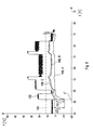
- FIG. 6 is a highly schematic of an example course of temperatures inside a refrigerated container 136 shown. Based on these temperature profiles, the effects of the cooling element 110 according to the invention will be explained.
- the time t is plotted in hours.
- the units shown are each 12-hour units, ie one graduation on the scale corresponds to 12 hours.
- the temperature in ° C is plotted on the y-axis.
- a refrigerated goods 140 was assumed, which has a typical limit 160, which in FIG. 6 indicated by dashed lines.
- This limit 160 should not or not be permanently exceeded (for example, for no more than a predetermined total period) and thus represents, for example, a maximum temperature for storage.
- this limit may be 12 ° C, which is a common size for typical medicines.
- this limit 160 is highly dependent on the type of goods to be cooled 140.
- the curve 162 describes an outside temperature profile in a climatic chamber into which a refrigerated container 136 has been introduced.
- the illustrated profile of the outside temperature 162 is subject to fluctuations, which may be due to the time of day, for example.
- the illustrated temperature profile is, for example, a temperature profile which corresponds approximately to a summer profile.
- FIG. 4B be a point denoted by A.
- the cooling element 110 surrounded with a generally uninsulated enclosure 112, but also an at least partially insulated embodiment is conceivable. In the present case, however, it is assumed that the temperature profile 164 was recorded in an uninsulated enclosure 112, so that this temperature profile 164 approximately represents the temperature profile in the region of the memory element 148.
- the curve 166 describes the temperature profile on the heat transfer wall 122.
- this may be a measurement in the point which is in FIG. 4B symbolically denoted by B.
- the curve 168 describes a temperature profile on a sample arranged in the immediate vicinity of the cooling element 110, for example the product to be cooled 140 in FIG FIG. 5 , For example, this may be a measurement on the in FIG. 5 be designated C point of the item to be cooled 140.
- a supercooled cooling element 110 is introduced into the refrigerated container 136.
- the cooling element 110 may be undercooled to a temperature of about -12 ° C.
- samples or refrigerated goods 140 which must not fall below a tolerance threshold or minimum temperature of 0 ° C, for example, even this cold shock would possibly lead to destruction.
- this effect is mitigated by the inventive design of the cooling element 140.
- the temperature at point B only drops to just below 0 ° C (curve 166), whereas the temperature on the goods to be cooled 140 at point C (curve 168) also remains immediately after the introduction of the cooling element 110 above 0 ° C.
- the initial temperature peak is thus buffered according to the invention.
- the amount of differential temperatures ⁇ T 1 and ⁇ T 2 in FIG. 6 For example, by suitable selection of the separating element 114, such as a fleece thickness and / or a nonwoven material, can be adjusted. In this way, the cooling element can be adjusted very precisely to the tolerance threshold of the product to be cooled 140.
- the curves 166 and 168 of the curve 164 do not follow each other in parallel, but approach this curve and show a flatter course. This is due to the fact that according to the invention with increasing heat input into the cooling element 110 an increasing amount of liquid coolant 126 is formed, which causes an improved heat transfer between the goods to be cooled 140 and serving as the actual thermal storage solid coolant 124 in the fluid space 120. This significantly reduces the distance between the curves 164 and 166 or 168.
- This curve shows that, on the one hand, due to considerable hypothermia, a large thermal reservoir can be created in the cooling element 110, without causing damage to the cooling product 140.
- the heat transfer between the cooling element 110 and the goods to be cooled 140 is designed to be variable in time, which causes an extension of the maximum service life of the cooling element 110.
Abstract
Description
Die Erfindung betrifft ein Kühlelement zum Kühlen eines Kühlguts sowie einen Kühlcontainer mit einem erfindungsgemäßen Kühlelement. Weiterhin betrifft die Erfmdung ein Verfahren zum Kühlen eines Kühlguts unter Verwendung eines erfindungsgemäßen Kühlelements sowie ein Verfahren zur Herstellung eines Kühlelements. Derartige Kühlelemente, Kühlcontainer und Verfahren können insbesondere im Bereich der Pharmazie und Medizin zum Transport pharmazeutischer und/oder medizinischer Proben eingesetzt werden. Auch andere Anwendungen sind jedoch möglich.The invention relates to a cooling element for cooling a refrigerated goods and a refrigerated container with a cooling element according to the invention. Furthermore, the invention relates to a method for cooling a refrigerated product using a cooling element according to the invention and to a method for producing a cooling element. Such cooling elements, refrigerated containers and methods can be used in particular in the field of pharmacy and medicine for the transport of pharmaceutical and / or medical samples. However, other applications are possible.
Kühlelemente werden in zahlreichen Einsatzgebieten und Anwendungen eingesetzt. Als Beispiele, welche jedoch nicht abschließend sind, sind hier verschiedene Naturwissenschaften, wie beispielsweise die Chemie und die Biologie zu nennen, sowie die Medizin und Medizintechnik. Auch in der Pharmazie werden beispielsweise derartige Kühlelemente eingesetzt, um Medikamente bei einer optimalen Temperatur aufzubewahren und/oder zu transportieren. Daneben existieren Kühlelemente, welche im Haushaltsbereich eingesetzt werden oder Kühlelemente für den Bereich der Lebensmittelindustrie.Cooling elements are used in numerous applications and applications. As examples, which are not exhaustive, there are various natural sciences, such as chemistry and biology, as well as medicine and medical technology. Also in pharmacy, for example, such cooling elements are used to store medicines at an optimum temperature and / or to transport. In addition, there are cooling elements, which are used in the household sector or cooling elements for the food industry.
Derartige Kühlelemente, häufig auch "Kühlakkus" genannt, weisen üblicherweise eine flexible oder starre Umhüllung auf, in welche eine kältespeichernde Flüssigkeit (im Folgenden auch Kühlmittel genannt) eingebracht wird. Ist das Kühlelement "aufgeladen", so liegt die kältespeichernde Flüssigkeit im gefrorenen Zustand vor. Diese Flüssigkeit kann unmittelbar in der Umhüllung vorliegen oder in einem Trägersubstrat oder Speichermedium aufgenommen sein. Letzteres dient häufig der Immobilisierung und wirkt sich vorteilhaft auf die Formgebung des Kühlelementes und auf eine mögliche Kühldauer aus. Das Kühlelement wird vor dem Einsatz für eine vorgegebene Zeitdauer vorgefroren. Derartige Kühlelemente weisen in der Regel keine eigene aktive Kühlung auf, insbesondere keine Stromversorgung.Such cooling elements, often also called "cooling batteries", usually have a flexible or rigid enclosure into which a cold accumulating liquid (also referred to below as coolant) is introduced. If the cooling element is "charged", then the cold accumulating liquid is present in the frozen state. This liquid may be present directly in the enclosure or incorporated in a carrier substrate or storage medium. The latter is often used for immobilization and has an advantageous effect on the shape of the cooling element and on a possible cooling time. The Cooling element is pre-frozen for a predetermined period of time before use. As a rule, such cooling elements do not have their own active cooling, in particular no power supply.
Nachteilig an derartigen Kühlelementen oder Kühlakkus ist jedoch, dass ein derartiges Vorfrieren beziehungsweise Unterkühlen auf eine Temperatur unterhalb der Zieltemperatur des Kühlgutes üblicherweise Temperaturen deutlich unterhalb des Phasenübergangs zwischen festem Aggregatszustand und flüssigem Aggregatszustand des Kühlmittels bewirkt. Durch dieses Unterkühlen der Kühlelemente unterhalb der letztendlich gewünschten Zieltemperatur des Kühlgutes beziehungsweise der Ware ist es erst möglich, die Kühlung über einen längeren Zeitraum aufrechtzuerhalten. Insofern ist eine derartige Unterkühlung der Kühlelemente in vielen Fällen unverzichtbar.A disadvantage of such cooling elements or cooling batteries, however, is that such Vorvorieren or sub-cooling to a temperature below the target temperature of the cooling material usually causes temperatures well below the phase transition between solid state and liquid state of aggregation of the coolant. As a result of this subcooling of the cooling elements below the ultimately desired target temperature of the goods to be cooled or of the goods, it is only possible to maintain the cooling over a longer period of time. In this respect, such a hypothermia of the cooling elements is indispensable in many cases.
Bringt man jedoch derartig unterkühlte Kühlelemente in eine Verpackung ein, so erfolgt unter anderem auch in dem Bereich der Verpackung, welcher das Kühlgut beziehungsweise die zu kühlende Ware enthält, zunächst eine starke Abkühlung durch die unterkühlten Kühlelemente. Für viele Arten von Kühlgut, beispielsweise im Bereich der Lebensmittelindustrie und/oder der Pharmazie, sind derartige Unterkühlungen des Kühlgutes mit teilweise irreversiblen Beschädigungen verbunden. Bei Einsätzen im Haushalts- oder Lebensmittelbereich kann es zu Gefrierbrand oder anderen Beschädigungen kommen. Im Bereich der Pharmazie oder Biologie können empfmdliche Proben und Medikamente durch eine Unterkühlung vollständig unbrauchbar werden. Daher weisen Kühlgüter üblicherweise eine Zieltemperatur auf, bei welcher gekühlt werden sollte, eine Maximaltemperatur, welche auf Dauer nicht überschritten werden sollte, sowie eine Toleranzschwelle oder Minimaltemperatur unterhalb der Zieltemperatur, innerhalb derer in der Regel noch keine Beschädigungen auftreten.If, however, such undercooled cooling elements are introduced into a packaging, then, inter alia, in the region of the packaging which contains the goods to be cooled or the goods to be cooled, at first a strong cooling takes place through the undercooled cooling elements. For many types of refrigerated goods, for example in the food industry and / or pharmacy, such hypothermia of the refrigerated goods are associated with partially irreversible damage. Household or food use may cause freezer burn or other damage. In the field of pharmacy or biology, susceptible samples and drugs can become completely unusable due to hypothermia. Therefore, refrigerated goods usually have a target temperature at which should be cooled, a maximum temperature, which should not be exceeded over time, and a tolerance threshold or minimum temperature below the target temperature, within which usually no damage occurs.
Aus dem Stand der Technik sind verschiedene Lösungen bekannt, welche eingesetzt werden können, um ein Unterkühlen des Kühlgutes zu vermeiden. So beschreibt beispielsweise
Das aus der
Aus dem Stand der Technik sind auch komplexere Kühlsysteme bekannt, welche ebenfalls die oben beschriebene Problematik einer anfänglichen Unterkühlung des Kühlgutes vermeiden sollen. So beschreibt beispielsweise
Auch
Auch die in
Es ist daher eine Aufgabe der vorliegenden Erfindung, ein Kühlelement bereitzustellen, welches die Nachteile bekannter Kühlelemente zumindest weitgehend vermeidet. Insbesondere soll das Kühlelement einerseits das bekannte Problem eines anfänglichen schädlichen Unterkühlens temperaturempfindlichen Kühlguts, insbesondere beim Einbringen des Kühlguts in eine Transportverpackung beziehungsweise beim Einbringen von vorgefrorenen Kühlelementen in die Transportverpackungen, reduzieren beziehungsweise eliminieren. Andererseits soll das Kühlelement jedoch möglichst einfach ausgestaltet sein und soll das Erfordernis zusätzlicher Arbeitsschritte oder zusätzlicher Materialien zumindest weitgehend vermeiden. Weiterhin sollen die Temperaturübergänge und Temperaturverhältnisse innerhalb einer die Kühlelemente umfassenden Verpackung möglichst definiert sein, um zuverlässige Aussagen über die Kühltemperatur und Kühldauer der darin verpackten Ware liefern zu können.It is therefore an object of the present invention to provide a cooling element which at least largely avoids the disadvantages of known cooling elements. In particular, the cooling element should on the one hand reduce or eliminate the known problem of an initial harmful undercooling of temperature-sensitive refrigerated goods, in particular when introducing the refrigerated goods into a transport packaging or during the introduction of pre-frozen cooling elements into the transport packaging. On the other hand, the cooling element should, however, be as simple as possible and should at least largely avoid the requirement of additional work steps or additional materials. Furthermore, the temperature transitions and temperature conditions within a packaging comprising the cooling elements should be defined as much as possible in order to be able to provide reliable information about the cooling temperature and cooling time of the goods packed therein.
Diese Aufgabe wird durch die Erfindung mit den Merkmalen der unabhängigen Ansprüche gelöst. Vorteilhafte Weiterbildungen der Erfmdung sind in den Unteransprüchen gekennzeichnet. Der Wortlaut sämtlicher Ansprüche wird hiermit durch Bezugnahme zum Inhalt dieser Beschreibung gemacht.This object is achieved by the invention with the features of the independent claims. Advantageous developments of the invention are characterized in the subclaims. The wording of all claims is hereby incorporated by reference into the content of this specification.
Im Gegensatz zu den aus dem Stand der Technik bekannten "Pufferkonzepten" mit einfachen Isolationsschichtpuffern oder thermischen Puffermedien beruht die vorliegende Erfmdung auf einer gezielten Ausnutzung eines Phasenübergangs eines Kühlmittels vom festen Aggregatszustand in den flüssigen Aggregatszustand. Dabei ist im Sinne der vorliegenden Erfmdung unter einem "flüssigen Aggregatszustand" allgemein jedoch ein fluider Aggregatszustand zu verstehen, also ein Aggregatszustand, in welchem das Kühlmittel eine geringe Viskosität und hohe Verformbarkeit aufweist, also insbesondere eine Fließfähigkeit und/oder Strömfähigkeit. Neben flüssigen Kühlmitteln können dies grundsätzlich auch Kühlmittel im gasförmigen Zustand sein.In contrast to the "buffer concepts" known from the prior art with simple insulation layer buffers or thermal buffer media, the present invention is based on a targeted utilization of a phase transition of a coolant from the solid state of aggregation into the liquid state of aggregation. However, for the purposes of the present invention, a "liquid state of aggregation" generally refers to a fluid state of aggregation, that is to say an aggregate state in which the coolant has a low viscosity and high ductility, ie in particular a flowability and / or flowability. Aside from liquid coolants, these can in principle also be coolants in the gaseous state.
Ein Grundgedanke der vorliegenden Erfmdung besteht darin, dass ein Phasenübergang zwischen dem festen Aggregatszustand und dem flüssigen Aggregatszustand unter bekannten Randbedingungen stets bei einem bekannten Schmelzpunkt und/oder innerhalb eines bekannten Schmelzbereiches (je nach Art des Kühlmittels oder Kühlmittelgemischs) stattfmdet. Die Erfmdung beruht auf der Erkenntnis, dass es möglich ist, den festen Aggregatszustand des Kühlmittels und den flüssigen Aggregatszustand des Kühlmittels innerhalb eines Kühlelements räumlich zu trennen. Dementsprechend kann beispielsweise ein Vorrat des Kühlmittels im festen Aggregatszustand nahezu beliebig heruntergekühlt beziehungsweise unterkühlt werden, solange dieser ausreichend von dem Kühlgut thermisch getrennt und/oder isoliert wird. Dem flüssigen Aggregatszustand des Kühlmediums, welcher eine Temperatur von mindestens der Temperatur des Schmelzpunktes und/oder Schmelzbereichs aufweist, kann es hingegen durch geeignete Vorrichtungen ermöglicht werden, in engeren thermischen Kontakt mit dem Kühlgut zu treten und somit als Wärmeübertragungsmedium zwischen dem Kühlgut und dem festen Aggregatszustand des Kühlmittels zu wirken.A basic idea of the present invention is that a phase transition between the solid state of aggregation and the liquid state of aggregation is known Boundary conditions always at a known melting point and / or within a known melting range (depending on the nature of the coolant or coolant mixture) stattfmdet. The invention is based on the recognition that it is possible to spatially separate the solid state of aggregation of the coolant and the liquid state of aggregation of the coolant within a cooling element. Accordingly, for example, a supply of the coolant in the solid state can be cooled down or subcooled almost as long as it is sufficiently thermally separated and / or isolated from the material to be cooled. By contrast, the liquid state of aggregation of the cooling medium, which has a temperature of at least the temperature of the melting point and / or melting range, can be made possible by suitable devices to come into closer thermal contact with the goods to be cooled and thus as a heat transfer medium between the goods to be cooled and the solid state of aggregation to act of the coolant.
Zur Umsetzung dieses Gedankens wird daher ein Kühlelement vorgeschlagen, welches zum Kühlen eines Kühlguts eingesetzt werden kann. Das Kühlgut kann beispielsweise, wie oben dargestellt, aus dem Bereich der Naturwissenschaften, der Medizin, der Pharmazie, der Lebensmittelindustrie oder aus dem Haushaltsbereich entnommen sein. Auch andere Einsatzgebiete sind jedoch denkbar. Insbesondere kann das Kühlgut thermisch sensitives Kühlgut umfassen, welches nicht unterhalb einer bestimmten Minimaltemperatur und/oder unterhalb einer Toleranzschwelle unterhalb einer Zieltemperatur gekühlt werden sollte.To implement this idea, therefore, a cooling element is proposed, which can be used for cooling a refrigerated goods. The refrigerated goods can, for example, as shown above, be taken from the field of natural sciences, medicine, pharmacy, food industry or household. However, other applications are conceivable. In particular, the item to be cooled may comprise thermally sensitive item to be cooled, which should not be cooled below a certain minimum temperature and / or below a tolerance threshold below a target temperature.
Das Kühlelement umfasst eine Umhüllung, welche insbesondere als geschlossene Umhüllung ausgestaltet sein kann. Diese Umhüllung kann, wie unten näher dargestellt wird, eine flexible und/oder starre Umhüllung umfassen. Besonders geeignet als Materialien für derartige Umhüllungen sind Kunststoffe, insbesondere Kunststofffolien oder Kunststoffplatten. Aufgrund ihrer geringen Durchlässigkeit haben sich insbesondere Mischkunststoffe aus Polyethylen und Polyamid als vorteilhaft erwiesen. Die Umhüllung kann auch mehrlagig ausgestaltet sein und kann beispielsweise in unterschiedlichen Bereichen des Kühlelements unterschiedlich ausgestaltet sein, beispielsweise um anisotrop eine unterschiedliche Wärmeübertragung in unterschiedlichen Bereichen der Umhüllung zu ermöglichen.The cooling element comprises an envelope, which may be configured in particular as a closed envelope. This enclosure may include a flexible and / or rigid enclosure, as further detailed below. Particularly suitable as materials for such sheaths are plastics, in particular plastic films or plastic sheets. Due to their low permeability in particular mixed plastics of polyethylene and polyamide have proven to be advantageous. The envelope can also be designed in several layers and can be designed differently, for example, in different areas of the cooling element, for example, to allow anisotropic different heat transfer in different areas of the enclosure.
So weist die Umhüllung insbesondere mindestens eine Wärmeübertragungswand zum Austausch thermischer Energie mit dem Kühlgut auf. Beispielsweise kann die Umhüllung genau eine Wärmeübertragungswand aufweisen, beispielsweise eine ebene Wärmeübertragungswand. Beispielsweise kann es sich bei dieser Wärmeübertragungswand um eine oder mehrere Folienseiten einer Folienumhüllung, beispielsweise eines Folienbeutels, handeln.Thus, the envelope in particular has at least one heat transfer wall for exchanging thermal energy with the refrigerated goods. For example, the enclosure may have exactly one heat transfer wall, for example a planar heat transfer wall. By way of example, this heat transfer wall may be one or more sides of a film wrapping, for example a film bag.
Unter dem Ausdruck "zum Austausch thermischer Energie mit dem Kühlgut" ist dabei jedoch nicht notwendigerweise ein direkter thermischer Kontakt mit dem Kühlgut zu verstehen, so dass beispielsweise auch, neben einem direkten Kontakt mit dem Kühlgut, eine Zwischenschaltung weiterer thermisch isolierender Elemente, wie beispielsweise Schaumstoff- oder Styroporelemente, und/oder auch Luft- oder Gasschichten möglich sein kann.However, the term "for exchanging thermal energy with the refrigerated goods" is not necessarily to be understood as a direct thermal contact with the refrigerated goods, so that, for example, in addition to a direct contact with the refrigerated goods, an interposition of other thermally insulating elements, such as foam - Or Styrofoam elements, and / or air or gas layers may be possible.
Zur Umsetzung des oben beschriebenen Grundgedankens der räumlichen Trennung der Phasen des Kühlmittels weist das Kühlelement mindestens einen an die Wärmeübertragungswand angrenzenden Fluidraum und mindestens einen von dem Fluidraum getrennten Speicherraum auf. Der Fluidraum und der Speicherraum sind durch mindestens ein Trennelement getrennt. Der Begriff "Trennen" bezieht sich hier auf einen mechanischen Rückhalt der festen Phase des Kühlmittels (siehe die nachfolgende Beschreibung) und ein zumindest weitgehendes Fernhalten dieser festen Phase von dem Fluidraum. Vorzugsweise betrifft die Trennung jedoch, wie unten ausgeführt, zusätzlich auch eine thermische Trennung, also eine zumindest teilweise thermische Isolation.In order to implement the above-described basic idea of the spatial separation of the phases of the coolant, the cooling element has at least one fluid space adjoining the heat transfer wall and at least one storage space separated from the fluid space. The fluid space and the storage space are separated by at least one separating element. The term "separation" here refers to a mechanical retention of the solid phase of the coolant (see the description below) and at least largely keeping this solid phase away from the fluid space. Preferably, however, the separation, as explained below, additionally also relates to a thermal separation, that is to say an at least partial thermal insulation.
Als fester Aggregatszustand wird im Sinne der vorliegenden Anmeldung auch ein zähflüssiger Zustand eines Kühlmittels verstanden, bei welchem die Viskosität des Kühlmittels so hoch ist, dass das Kühlmittel in diesem zähflüssigen Zustand nicht in den durch mindestens ein Trennelement getrennten Fluidraum strömen kann. Als flüssiger Aggregatszustand wird im Sinne der vorliegenden Anmeldung auch ein flüssiger Zustand eines Kühlmittels verstanden, bei welchem die Viskosität des Kühlmittels entsprechend gering ist, dass das Kühlmittel in diesem flüssigen Zustand in den durch mindestens ein Trennelement getrennten Fluidraum strömen kann. Beispiele für solche Kühlmittel können beispielsweise Parafme oder wachsähnliche Substanzen sein.For the purposes of the present application, a solid state of aggregation is also understood to mean a viscous state of a coolant in which the viscosity of the coolant is so high that the coolant in this viscous state can not flow into the fluid space separated by at least one separating element. For the purposes of the present application, a liquid state of aggregation is also understood to mean a liquid state of a coolant in which the viscosity of the coolant is correspondingly low, so that the coolant in this liquid state can flow into the fluid space separated by at least one separating element. Examples of such coolants may be, for example, paraffins or wax-like substances.
Der Speicherraum ist eingerichtet, um einen Kühlmittelvorrat in festem Aggregatszustand aufzunehmen. Beispielsweise kann es sich hierbei um einen oder mehrere feste Blöcke des Kühlmittels handeln, welche eine nahezu beliebige geometrische Gestalt annehmen können. Wie unten ausgeführt, kann der Speicherraum zusätzlich mindestens ein Speicherelement zum Aufnehmen des Kühlmittelvorrats aufweisen, was jedoch nicht zwingend erforderlich ist.The storage space is set up to receive a coolant supply in a fixed state of aggregation. For example, this may be one or more solid blocks of the coolant, which may assume a virtually random geometric shape. As explained below, the storage space can additionally have at least one storage element for receiving the coolant supply, although this is not absolutely necessary.
Das Trennelement ist eingerichtet, um den Kühlmittelvorrat im festen Aggregatszustand von dem Fluidraum im Wesentlichen fernzuhalten. Unter "im Wesentlichen" in diesem Zusammenhang ist zu verstehen, dass der Fluidraum vorzugsweise nicht mehr als 5 %, vorzugsweise nicht mehr als 1 % des Kühlmittels in gefrorenem Zustand aufweisen soll.The separator is configured to substantially keep the coolant supply in the solid state from the fluid space substantially. By "substantially" in this context is meant that the fluid space should preferably not have more than 5%, preferably not more than 1% of the refrigerant in the frozen state.
Das Fernhalten des festen Aggregatszustands von dem Fluidraum kann, wie unten anhand von Beispielen näher ausgeführt wird, durch einen einfachen mechanischen Rückhalt erfolgen, welcher voluminöse Bruchstücke des Kühlmittels im festen Zustand beispielsweise mittels entsprechend klein dimensionierter Fluidkanäle von dem Fluidraum fernhält. Kühlmittel in flüssigem Aggregatszustand soll jedoch der Übertritt von dem Speicherraum in den Fluidraum ermöglicht werden.Keeping away the solid state of aggregation from the fluid space can, as will be further exemplified below, be accomplished by a simple mechanical retention which keeps voluminous debris of the solid state coolant away from the fluid space, for example by means of correspondingly small sized fluid channels. However, coolant in the liquid state of aggregation should be allowed to pass from the storage space into the fluid space.
Durch das erfindungsgemäße Konzept der zumindest teilweisen räumlichen Trennung von Kühlmittel in festem Aggregatszustand und flüssigem Aggregatszustand, wobei vorzugsweise ausschließlich das flüssige Kühlmittel in engeren thermischen Kontakt mit dem Kühlgut treten kann, werden die oben beschriebenen Nachteile bekannter Kühlkonzepte auf geschickte Weise vermieden. Der Kühlmittelvorrat des festen Kühlmittels kann nahezu beliebig unterkühlt werden, ohne dass eine Schädigung des Kühlguts zu befürchten ist. Dennoch ist sichergestellt, dass ausschließlich Kühlmittel, welches in den flüssigen Aggregatszustand übergegangen ist, in engeren thermischen Kontakt mit dem Kühlgut tritt, so dass dieses Kühlmittel stets eine bekannte Minimaltemperatur aufweist. Der beschriebene Aufbau ermöglicht somit lange Kühldauern, im Gegensatz zu den bekannten "Pufferkonzepten", bei gleichzeitig hoher Unterkühlungssicherheit. Weiterhin kann das Kühlelement vergleichsweise einfach aufgebaut sein, im Gegensatz beispielsweise zu den komplexen Mehrkammersystemen der
Das erfindungsgemäße Kühlelement kann auf verschiedene Weisen vorteilhaft weiterentwickelt werden. Diese optionalen Weiterentwicklungen können einzeln oder in Kombination realisiert sein.The cooling element according to the invention can be further developed in various ways advantageous. These optional developments can be implemented individually or in combination.
So kann das Kühlelement in dem Speicherraum, wie oben beschrieben, mindestens ein Speicherelement aufweisen, welches eingerichtet ist, um den Kühlmittelvorrat ganz oder teilweise aufzunehmen und zumindest teilweise zu immobilisieren. Auf diese Weise kann eine räumliche Konzentration des Kühlmittelsvorrats, insbesondere in festem Aggregatszustand, erleichtert werden, im Gegensatz beispielsweise zu einer Verfestigung im Rahmen einzelner, untereinander nicht verbundener Feststoffpartikel, welche ungleich schwerer durch das Trennelement zurückgehalten werden können.Thus, the cooling element in the storage space, as described above, at least one storage element having, which is adapted to receive the coolant supply in whole or in part and at least partially immobilize. In this way, it is possible to facilitate a spatial concentration of the coolant supply, in particular in a solid state of aggregation, in contrast, for example, to solidification in the context of individual solid particles which are not interconnected and which can be retained with greater difficulty by the separating element.
Diese Immobilisierung, also die Verringerung der räumlichen Beweglichkeit durch Vergrößerung einer zusammenhängenden, räumlich konzentrierten Masse insbesondere an festem Kühlmittel, kann auf verschiedene Weise erfolgen. So kann das Speicherelement beispielsweise den Kühlmittelvorrat mechanisch, durch Adsorption und/oder durch Absorption aufnehmen. Insbesondere kann das Speicherelement mindestens ein schwammartiges Element aufweisen, also ein Element mit einer Vielzahl von Poren zur Aufnahme des Kühlmittelvorrats. Das schwammartige Element kann einen Werkstoff aufweisen, welcher beispielsweise von seinen Oberflächeneigenschaften her gut für die Aufnahme des Kühlmittels geeignet ist. Allgemein kann, alternativ oder zusätzlich, das Speicherelement auch ein Schaumsubstrat, einen Kunststoffschaum, insbesondere einen Melaminharzschaum, einen Superabsorber, ein Quellmittel oder ähnliche Werkstoffe umfassen. Alternativ oder zusätzlich kann das Speicherelement auch weitere Zusätze, beispielsweise Netzmittel zur besseren Befüllung des Speicherelements mit dem Kühlmittel, umfassen. Alternativ oder zusätzlich kann das Speicherelement auch mindestens ein Immobilisierungsmedium umfassen, welches eingerichtet ist, um das Kühlmittel einzudicken und auf diese Weise die Mobilität des Kühlmittels zu verringern. Beispielsweise kann als Immobilisierungsmedium Gelatine, Agar-Agar, Pektin, Polyvinylalkohol oder ein ähnliches Medium verwendet werden.This immobilization, ie the reduction of the spatial mobility by increasing a coherent, spatially concentrated mass, in particular on solid coolant, can be done in various ways. For example, the storage element can absorb the coolant supply mechanically, by adsorption and / or by absorption. In particular, the storage element may comprise at least one sponge-like element, that is, an element having a plurality of pores for receiving the coolant supply. The sponge-like element may comprise a material which is well suited, for example, for its surface properties for receiving the coolant. Generally, alternatively or additionally, the storage element may also comprise a foam substrate, a plastic foam, in particular a melamine resin foam, a superabsorber, a swelling agent or similar materials. Alternatively or additionally, the storage element may also comprise further additives, for example wetting agents for better filling of the storage element with the coolant. Alternatively or additionally, the storage element may also comprise at least one immobilization medium, which is set up to thicken the coolant and in this way reduce the mobility of the coolant. For example, gelatin, agar agar, pectin, polyvinyl alcohol or the like may be used as the immobilizing medium.
Der Kühlmittelvorrat kann ganz oder teilweise in dem Speicherelement aufgenommen sein. Das Speicherelement kann dann eingerichtet sein, um lediglich den festen Kühlmittelvorrat aufzunehmen, wohingegen dem Kühlmittel im flüssigen Aggregatszustand eine Zirkulation hin zu dem Fluidraum ermöglicht sein soll. Zu diesem Zweck kann das Speicherelement beispielsweise unterschiedliche Rückhalteeigenschaften für das Kühlmittel in festem und flüssigem Aggregatszustand aufweisen, so dass sich beispielsweise Kühlmittel, welches in den flüssigen Aggregatszustand übergegangen ist, leichter von dem Speicherelement löst. Hierzu können beispielsweise gezielt Oberflächeneigenschaften des Speicherelements eingestellt werden. Alternativ oder zusätzlich können auch Volumenänderungen beim Phasenübergang eingesetzt werden. So kann beispielsweise der Kühlmittelvorrat derart bemessen sein, dass dieser das Speicherelement in flüssigem Zustand vollständig sättigt. Beim Gefrieren, das heißt beim Phasenübergang in den festen Aggregatszustand, kann dann beispielsweise eine Volumenzunahme erfolgen, wie dies bei verschiedenen Kühlmitteln, wie beispielsweise Wasser, der Fall ist. Das "überschüssige" Volumen kann dann beispielsweise auf der Außenseite des Speicherelements angesammelt sein und kann leichter in den flüssigen Zustand übergehen und zirkulieren.The coolant supply may be wholly or partially received in the storage element. The storage element may then be arranged to receive only the fixed coolant supply, whereas the coolant in the liquid state of aggregation should be allowed to circulate to the fluid space. For this purpose, the storage element, for example, have different retention properties for the coolant in the solid and liquid state of aggregation, so that, for example, coolant, which has passed into the liquid state of aggregation, more easily detached from the storage element. For this purpose, for example, surface properties of the storage element can be set specifically. Alternatively or additionally, changes in volume during the phase transition can also be used. For example, the coolant supply can be dimensioned such that it completely saturates the storage element in the liquid state. When freezing, that is the phase transition into the solid state of aggregation, then, for example, an increase in volume can take place, as is the case with different coolants, such as water. The "excess" volume may then be accumulated, for example, on the outside of the storage element and may more easily transition to the liquid state and circulate.
Weitere vorteilhafte Ausgestaltungen der Erfmdung beziehen sich auf die Ausgestaltung des mindestens einen Trennelements und auf die Ausgestaltung der Ermöglichung eines Überströmens des flüssigen Kühlmittels in den Fluidraum. So können beispielsweise der mindestens eine Speicherraum und der mindestens eine Fluidraum durch mindestens einen Fluidkanal miteinander in Verbindung stehen. Dieser mindestens eine Fluidkanal kann auf verschiedene Weise ausgestaltet sein und sollte derart dimensioniert sein, dass dieser zumindest größeren Stücken des Kühlmittels im gefrorenen Zustand, das heißt in festem Aggregatszustand, den Übertritt in den Fluidraum verwehrt. Beispielsweise kann der Fluidkanal ganz oder teilweise in dem mindestens einen Trennelement ausgestaltet sein. So kann der Fluidkanal beispielsweise in Form mindestens einer Bohrung und/oder mindestens einer Öffnung das Trennelement durchsetzen. Auch eine Vielzahl von Bohrungen und/oder Öffnungen ist denkbar, beispielsweise in Form eines Siebs. Auch ein poröses Trennelement ist denkbar, wobei in diesem Fall die Poren derart ausgestaltet sein sollten, dass diese einen Durchtritt des flüssigen Kühlmittels ermöglichen.Further advantageous embodiments of the invention relate to the design of the at least one separating element and to the embodiment of enabling an overflow of the liquid coolant into the fluid space. Thus, for example, the at least one storage space and the at least one fluid space can communicate with one another through at least one fluid channel. This at least one fluid channel can be designed in various ways and should be dimensioned such that this at least larger pieces of coolant in the frozen state, that is, in a solid state, denied the passage into the fluid space. For example, the fluid channel can be wholly or partially configured in the at least one separating element. For example, the fluid channel can pass through the separating element in the form of at least one bore and / or at least one opening. Also, a plurality of holes and / or openings is conceivable, for example in the form of a sieve. A porous separating element is also conceivable, in which case the pores should be configured such that they allow passage of the liquid coolant.
Alternativ oder zusätzlich kann der mindestens eine Fluidkanal auch beispielsweise durch eine Kombination des Trennelements und der Umhüllung und/oder eines zusätzlichen Bauteils gebildet sein. Beispielsweise kann der Fluidkanal zwischen dem Trennelement und der Umhüllung ausgebildet sein. Um den Fluidkanal offen zu halten und/oder um den Fluidkanal auf einer bestimmten Dimensionierung zu halten, können zu diesem Zweck beispielsweise Trennstege vorgesehen sein, welche zwischen dem Trennelement und der Umhüllung ausgebildet sind. Diese Trennstege können ganz oder teilweise beispielsweise Bestandteil des Trennelements sein und/oder können Bestandteil der Umhüllung sein und/oder können zumindest teilweise als eigenständiges Bauteil ausgebildet sein. Beispielsweise kann die Umhüllung überdimensioniert sein, so dass ein Umfließen des Trennelements durch das flüssige Kühlmittel ermöglicht wird. Die Verwendung von Trennstegen bietet sich insbesondere bei starren Umhüllungen an, ist jedoch auch bei flexiblen Umhüllungen möglich. Die Trennstege wirken in diesem Fall beispielsweise als Abstandshalter an der Innenseite der Umhüllung. Durch diese vorgeschlagenen möglichen Ausgestaltungen des Fluidkanals und/oder der Umhüllung beziehungsweise des Trennelements ist eine besonders wirksame Trennung zwischen der flüssigen und festen Phase des Kühlmittels realisierbar, bei gleichzeitig vergleichsweise einfachem und kostengünstigem Aufbau.Alternatively or additionally, the at least one fluid channel can also be formed, for example, by a combination of the separating element and the casing and / or an additional component. For example, the fluid channel can be formed between the separating element and the envelope. In order to keep the fluid channel open and / or to keep the fluid channel to a specific dimensioning, separating webs may be provided for this purpose, for example, which are formed between the separating element and the casing. These partitions may be wholly or partly, for example, part of the separating element and / or may be part of the enclosure and / or may be at least partially formed as an independent component. For example, the enclosure may be oversized, so that a circulation of the separating element is made possible by the liquid coolant. The use of dividers is particularly suitable for rigid sheaths, but is also possible with flexible sheaths. The partitions act in this case, for example, as a spacer on the inside of the enclosure. By these proposed possible embodiments of the fluid channel and / or the enclosure or the separating element, a particularly effective separation between the liquid and solid phase of the coolant can be realized, at the same time comparatively simple and inexpensive construction.
Weitere vorteilhafte Ausgestaltungen betreffen das Trennelement. Wie oben beschrieben, kann das Trennelement insbesondere, allein oder in Zusammenwirkung mit der Umhüllung, den mindestens einen Fluidkanal ausbilden. Weiterhin kann das Trennelement beispielsweise mindestens ein blattförmiges, plattenförmiges oder scheibenförmiges Trennelement umfassen, also allgemein ein Element, dessen laterale Abmessungen seine Dicke um ein Mehrfaches übersteigen. In diesem Fall sollte zwischen dem Trennelement und der Umhüllung mindestens ein als Fluidspalt ausgestalteter Fluidkanal zum Austausch von fluidem Kühlmittel zwischen dem Speicherraum und dem Fluidraum ausgebildet sein. Das Kühlmittel kann also in flüssigem Aggregatszustand durch Umströmen des blatt-, platten- oder scheibenförmigen Trennelements in den Fluidraum gelangen. Anstelle eines einzelnen blatt-, platten- oder scheibenförmigen Trennelements, also eines Elements, dessen laterale Ausdehnungen seine Dicke um ein Mehrfaches übersteigen, ist auch die Verwendung einer Mehrzahl derartiger Elemente denkbar. So kann beispielsweise das Trennelement eine Mehrzahl von aufeinander gestapelten blattförmigen, plattenförmigen oder scheibenförmigen Trennelementen umfassen. Diese Mehrzahl an derartigen Trennelementen kann beispielsweise ein mehrfaches Umströmen erforderlich machen, bis das flüssige Kühlmittel in den Fluidraum gelangt. Auf diese Weise oder auf andere Weise lässt sich auch eine Labyrinthstruktur oder eine labyrinthartige Struktur schaffen und als Trennelement oder als Bestandteil des Trennelements einsetzen. Zudem lässt sich auf diese Weise eine gute thermische Isolation zwischen dem Kühlmittel in festem Aggregatszustand und dem Fluidraum beziehungsweise dem Kühlgut erreichen. Ein weiterer Vorteil der Verwendung einer Mehrzahl von einzelnen Trennelemente liegt darin, dass durch die Variation der Anzahl und/oder der thermischen Eigenschaften der einzelnen Trennelemente die thermischen Eigenschaften, insbesondere die thermisch isolierenden Eigenschaften wie Wärmeleitfähigkeit oder Wärmedurchlasswiderstand, der gesamten Trennelement-Struktur auf einfache Weise an verschiedenen Anforderungen angepasst werden können, beispielsweise durch Variation der Anzahl der Lagen einzelner Trennelemente.Further advantageous embodiments relate to the separating element. As described above, the separating element may in particular, alone or in cooperation with the enclosure, form the at least one fluid channel. Furthermore, the separating element may, for example, at least one sheet-shaped, plate-shaped or disc-shaped separating element include, in general, an element whose lateral dimensions exceed its thickness by a multiple. In this case, at least one fluid channel designed as a fluid gap should be formed between the separating element and the casing for exchanging fluid coolant between the storage space and the fluid space. The coolant can thus reach the fluid space by flowing around the sheet, plate or disc-shaped separating element in liquid state of aggregation. Instead of a single sheet, plate or disc-shaped separating element, ie an element whose lateral dimensions exceed its thickness by a multiple, the use of a plurality of such elements is conceivable. For example, the separating element may comprise a plurality of stacked, plate-shaped or disk-shaped separating elements stacked on one another. For example, this plurality of such separators may require multiple recirculation until the liquid coolant enters the fluid space. In this way or in another way, a labyrinth structure or a labyrinth-like structure can be created and used as a separating element or as part of the separating element. In addition, a good thermal insulation between the coolant in a fixed state of aggregation and the fluid space or the goods to be cooled can be achieved in this way. A further advantage of using a plurality of individual separating elements is that, by varying the number and / or the thermal properties of the individual separating elements, the thermal properties, in particular the thermally insulating properties such as thermal conductivity or thermal resistance, of the entire separating element structure in a simple manner can be adapted to different requirements, for example by varying the number of layers of individual separating elements.
Das Trennelement kann insbesondere mechanisch flexibel ausgestaltet sein. Insbesondere kann das Trennelement einen Vliesstoff umfassen, also einen nicht gewobenen oder nicht gestrickten oder gewirkten Stoff, insbesondere einen Kunststoff-Vliesstoff. Insbesondere kann der Kunststoff-Vliesstoff ein Kunststoffvlies aus extrudiertem Material mit kurzkettigen und langkettigen Anteilen und einer amorphen Struktur sein. Vliese, insbesondere poröse Vliese, haben sich als gut thermisch isolierend erwiesen und können gleichzeitig optimal auf die erforderlichen Eigenschaften (beispielsweise eine geringe Benetzung und/oder Aufnahme des Kühlmittels) angepasst werden. Insbesondere kann das Kühlelement ein oder mehrere Lagen einer flexiblen Isolationsschicht, beispielsweise eines flexiblen Vlieses, umfassen. Weiterhin sind, alternativ oder zusätzlich, extrudierte thermisch isolierende Kunststoffe, insbesondere Polyethylene, Polystyrole, Polypropylene, Polyamide oder andere Kunststoffe oder Mischkunststoffe einsetzbar. Derartig extrudierte Kunststoffe, beispielsweise wiederum Kunststoffvliese, weisen besonders günstige Eigenschaften auf, da diese einerseits thermisch isolierend sind und andererseits einen geringen Anteil an Lufteinschlüssen aufweisen, welche den oben beschriebenen Grundeffekt der Erfmdung vermindern könnten. Alternativ oder zusätzlich kann das mindestens eine Trennelement auch eine oder mehrere Isolationselemente umfassen, beispielsweise eine oder mehrere evakuierte Trägerplatten oder Isolationselemente mit gasförmigen Isolationsmedien. Durch Anpassung der Materialien und/oder der Ausgestaltungen des Trennelements können beispielsweise die Isolationsleistung des Trennelements, also die thermische Isolierung des Speicherraums gegenüber dem Fluidraum und/oder gegenüber dem Kühlmedium, in weiten Bereichen beeinflusst werden. Beispielsweise kann dies bei der Verwendung von isolierenden Vliesen durch die Wahl der Anzahl der Lagen des Vliesstoffs auf einfache Weise erfolgen.The separating element can in particular be made mechanically flexible. In particular, the separating element may comprise a nonwoven fabric, ie a nonwoven or non-knitted or knitted fabric, in particular a nonwoven plastic material. In particular, the plastic nonwoven fabric may be a plastic nonwoven fabric of extruded material having short chain and long chain portions and an amorphous structure. Nonwovens, in particular porous nonwovens, have proved to be good thermal insulators and can at the same time be optimally adapted to the required properties (for example low wetting and / or uptake of the coolant). In particular, the cooling element may comprise one or more layers of a flexible insulation layer, for example a flexible nonwoven. Furthermore, as an alternative or in addition, extruded thermally insulating plastics, in particular polyethylenes, polystyrenes, polypropylenes, polyamides or other plastics or mixed plastics can be used. Such extruded plastics, for example, in turn plastic nonwovens, have particularly favorable properties on the one hand because they are thermally insulating and on the other hand have a low proportion of air pockets, which could reduce the basic effect of the invention described above. Alternatively or additionally, the at least one separating element may also comprise one or more insulating elements, for example one or more evacuated carrier plates or insulating elements with gaseous insulating media. By adapting the materials and / or the configurations of the separating element, for example, the insulating performance of the separating element, that is to say the thermal insulation of the storage space relative to the fluid space and / or to the cooling medium, can be influenced within wide ranges. For example, this can be done easily by the use of insulating webs by the choice of the number of layers of the nonwoven fabric.
Wie oben ausgeführt, kann das Trennelement insbesondere thermisch isolierende Eigenschaften aufweisen, um einen unmittelbaren Wärmeübergang von dem Kühlmittel in festem Aggregatszustand im Speicherraum hin zu dem Kühlgut zu reduzieren beziehungsweise einzuschränken. Dementsprechend ist es besonders bevorzugt, wenn das Trennelement eine Wärmeleitfähigkeit von 0,01 W/(m*K) bis 0,5 W/(m*K), besonders bevorzugt im Bereich von 0,035 W/(m*K), aufweist. Beispielsweise kann das Trennelement zu diesem Zweck ein oder mehrere entsprechende Isolationsmaterialien enthalten, die allein oder in Kombination die genannten Wärmeleitfähigkeiten bewirken. Alternativ oder zusätzlich ist es bevorzugt, wenn das Trennelement einen Wärmedurchlasswiderstand von mindestens 0,05 m2K/W aufweist. Auch zu diesem Zweck können ein oder mehrere entsprechende Isolationsmaterialien und/oder Isolationsmedien (wie beispielsweise gasgefüllte und/oder evakuierte Platten) vorgesehen sein, die die genannten Eigenschaften allein oder in ihrer Kombination bewirken.As stated above, the separating element may in particular have thermally insulating properties in order to reduce or restrict an immediate heat transfer from the coolant in a fixed state of aggregation in the storage space to the refrigerated goods. Accordingly, it is particularly preferred if the separating element has a thermal conductivity of 0.01 W / (m * K) to 0.5 W / (m * K), particularly preferably in the range of 0.035 W / (m * K). For example, for this purpose, the separating element may contain one or more corresponding insulating materials which, alone or in combination, cause said thermal conductivities. Alternatively or additionally, it is preferred if the separating element has a thermal resistance of at least 0.05 m 2 K / W. Also for this purpose, one or more appropriate insulation materials and / or isolation media (such as gas-filled and / or evacuated plates) may be provided, which cause the properties mentioned alone or in combination.
Eine weitere bevorzugte Ausgestaltung der Erfindung liegt darin, dass das Trennelement einen möglichst geringen Anteil des Kühlmittels in flüssigem und/oder festem Zustand aufnehmen sollte. Diese Weiterentwicklung hat den Vorteil, dass das Trennelement nicht oder nur in äußerst geringem Maße beim Unterkühlen Kühlmittel in festem Zustand aufnimmt, welches dann in engeren thermischen Kontakt mit dem Kühlgut geraten könnte. So werden viele Kühlelemente beispielsweise bei Raumtemperatur aufbewahrt, um dann erst vor dem Einsatz unterkühlt zu werden. Hätte das Trennelement ein großes Aufnahmevermögen für das flüssige Kühlmittel, so wäre dieses vor dem Unterkühlen beispielsweise bereits mit Kühlmittel getränkt, welches dann innerhalb dieses Trennelements gefrieren würde. Um dies zu verhindern, ist es besonders bevorzugt, wenn das Trennelement derart ausgestaltet ist, dass dieses einen Kühlmittelanteil von maximal 1 % aufnehmen kann, vorzugsweise sogar weniger, beispielsweise maximal 0,2 %.A further preferred embodiment of the invention is that the separating element should absorb the smallest possible proportion of the coolant in the liquid and / or solid state. This further development has the advantage that the separating element does not or only to a very small extent absorbs cooling agent in the solid state during subcooling, which could then come into closer thermal contact with the refrigerated goods. For example, many cooling elements are stored at room temperature, only to be subcooled before use. Had the separator a large capacity for the liquid coolant, so this would be soaked before subcooling, for example, already with coolant, which would then freeze within this separator. In order to prevent this, it is particularly preferred if the separating element is such is configured that this can accommodate a coolant content of at most 1%, preferably even less, for example, a maximum of 0.2%.
So kann beispielsweise das Kühlmittel ein polares Kühlmittel sein beziehungsweise mindestens eine polare Kühlmittelkomponente aufweisen, wobei das Trennelement in diesem Fall vorzugsweise zumindest abschnittsweise hydrophobe Eigenschaften aufweist. So kann beispielsweise als Kühlmittel Wasser verwendet werden, beispielsweise in Kombination mit einem hydrophoben Vlies als Trennelement, so dass eine geringe Aufnahme von Kühlmittel in dem Vlies sichergestellt ist. In manchen Fällen bietet es sich jedoch auch an, ein unpolares Kühlmittel zu verwenden beziehungsweise mindestens eine unpolare Kühlmittelkomponente. In diesem Fall ist es bevorzugt, wenn das Trennelement zumindest abschnittsweise hydrophile Eigenschaften aufweist.Thus, for example, the coolant may be a polar coolant or at least have a polar coolant component, wherein the separator in this case preferably has at least partially hydrophobic properties. Thus, for example, water can be used as the coolant, for example in combination with a hydrophobic nonwoven as the separating element, so that a low uptake of coolant in the nonwoven fabric is ensured. In some cases, however, it is also advisable to use a non-polar coolant or at least one non-polar coolant component. In this case, it is preferred if the separating element has hydrophilic properties at least in sections.
Das Kühlmittel kann auf verschiedene Weise ausgestaltet sein und kann insbesondere, wie unten beschrieben, an das Kühlgut angepasst sein. Allgemein soll das Kühlmittel ein Material mit einem geeigneten Schmelzpunkt und/oder Schmelzbereich sein, welches vorzugsweise eingerichtet ist, um beim Schmelzen eine latente Wärme aufzunehmen. Es lassen sich einzelne Kühlmittel oder auch Kühlmittelgemische einsetzen. Insbesondere lassen sich der Schmelzpunkt und/oder der Schmelzbereich in weiten Bereichen an optimale Temperaturen des Kühlgutes anpassen. Das Kühlmittel kann insbesondere Wasser oder Alkohol als polare Komponente aufweisen. Alternativ oder zusätzlich kann das Kühlmittel auch unpolare Komponenten umfassen, beispielsweise Öle, Fette, Paraffine oder ähnliche unpolare Flüssigkeiten. Während polare Flüssigkeiten insbesondere im Bereich bis 0 °C eingesetzt werden, lassen sich unpolare Flüssigkeiten beispielsweise als Kühlmittel im Bereich positiver Temperaturen, insbesondere im Bereich positiver Temperaturen unterhalb der Raumtemperatur, einsetzen.The coolant can be designed in various ways and, in particular, can be adapted to the goods to be cooled, as described below. Generally, the coolant should be a material having a suitable melting point and / or melting range, which is preferably adapted to receive latent heat upon melting. It is possible to use individual coolants or even coolant mixtures. In particular, the melting point and / or the melting range can be adjusted in a wide range of optimum temperatures of the refrigerated goods. The coolant may in particular comprise water or alcohol as a polar component. Alternatively or additionally, the coolant may also comprise non-polar components, for example oils, fats, paraffins or similar non-polar liquids. While polar liquids are used in particular in the range up to 0 ° C, non-polar liquids can be used for example as a coolant in the range of positive temperatures, in particular in the range of positive temperatures below room temperature.
Weiterhin lässt sich das Kühlmittel durch ein oder mehrere Additive in seinen Eigenschaften beeinflussen. Insbesondere kann durch geeignete Auswahl und/oder Konzentration derartiger Additive wiederum der Schmelzpunkt beziehungsweise Schmelzbereich eingestellt werden, sowie auch andere Eigenschaften, wie beispielsweise Viskosität, Polarität, Benetzungsvermögen oder ähnliches. So kann insbesondere mindestens ein Salz und/oder mindestens ein Zucker als Additiv eingesetzt werden. Beispielsweise lassen sich solehaltige wässrige Lösungen einsetzen, also Salz-Wasser-Lösungen, beispielsweise KochsalzLösungen.Furthermore, the coolant can be influenced by one or more additives in its properties. In particular, the melting point or melting range can in turn be adjusted by suitable selection and / or concentration of such additives, as well as other properties such as viscosity, polarity, wetting power or the like. Thus, in particular at least one salt and / or at least one sugar can be used as an additive. For example, sol-containing aqueous solutions can be used, ie salt-water solutions, for example saline solutions.
Weitere mögliche vorteilhafte Ausgestaltungen betreffen den Fluidraum. Unter einem "Raum" ist in diesem Zusammenhang allgemein mindestens ein Lumen zu verstehen, welches flüssiges Kühlmittel aufnehmen kann. Auch mehrere zusammenhängende oder voneinander getrennte Lumina sind möglich.Further possible advantageous embodiments relate to the fluid space. A "space" in this context is generally to be understood as meaning at least one lumen which can receive liquid coolant. Several contiguous or separate lumens are possible.
Der Fluidraum, welcher an die mindestens eine Wärmeübertragungswand direkt oder unter Zwischenschaltung zusätzlicher thermisch isolierender Elemente angrenzt, kann auf verschiedene Weise ausgestaltet sein. Insbesondere kann der Fluidraum ganz oder teilweise zwischen dem Trennelement und der Wärmeübertragungswand angeordnet sein. Hierbei ist üblicherweise ein Fluidraum von äußerst geringer Dicke ausreichend, beispielsweise ein lediglich geringer Spalt zwischen dem Trennelement und der Wärmeübertragungswand. Die Verwendung enger Dimensionierungen für den Fluidraum und/oder den Fluidkanal bietet darüber hinaus den Vorteil, dass Kapillarkräfte ausgenutzt werden können, um flüssiges Kühlmittel aus dem Speicherraum in den Fluidraum zu bewegen.The fluid space, which adjoins the at least one heat transfer wall directly or with the interposition of additional thermally insulating elements, can be designed in various ways. In particular, the fluid space can be arranged wholly or partly between the separating element and the heat transfer wall. In this case, usually a fluid space of extremely small thickness is sufficient, for example, only a small gap between the separating element and the heat transfer wall. The use of narrow dimensions for the fluid space and / or the fluid channel also offers the advantage that capillary forces can be utilized to move liquid coolant from the storage space into the fluid space.
Alternativ oder zusätzlich zu einer Ausgestaltung des Fluidraums zwischen dem Trennelement und der Wärmeübertragungswand kann der Fluidraum auch ganz oder teilweise in dem Trennelement enthalten sein. Insbesondere kann das Trennelement zu diesem Zweck, beispielsweise in einem der Wärmeübertragungswand zuweisenden Bereich, ein poröses Volumen aufweisen und/oder Rillen, Vertiefungen, Bohrungen oder ähnliches. Auch andere Ausgestaltungen sind möglich.As an alternative or in addition to an embodiment of the fluid space between the separating element and the heat transfer wall, the fluid space may also be wholly or partly contained in the separating element. In particular, for this purpose, for example in a region assigning the heat transfer wall, the separating element may have a porous volume and / or grooves, depressions, bores or the like. Other embodiments are possible.
Eine weitere Ausgestaltung betrifft die Umhüllung. Wie oben beschrieben, kann diese Umhüllung beispielsweise starr oder flexibel ausgestaltet sein und kann beispielsweise eine Folienumhüllung umfassen. Die Umhüllung kann auch mehrlagig ausgestaltet sein. Die Umhüllung kann insbesondere mindestens ein Isolierelement umfassen, welches einen Wärmeübertrag über mindestens eine Wand der Umhüllung zumindest teilweise verhindert und/oder verlangsamt. Für diese Isolierelemente, welche wiederum auch mehrlagig ausgestaltet sein können, können wiederum beispielsweise thermisch isolierende Kunststoffinaterialien und/oder Naturstoffmaterialien eingesetzt werden, welche bekanntermaßen einen Wärmeübertrag verhindern. Beispielsweise können zu diesem Zweck wiederum Schaumstoffe, andere Arten von porösen Materialien oder Vliesstoffe eingesetzt werden. Auch Gewebematerialien oder Gestrickmaterialien sind einsetzbar. Besonders bevorzugt ist es, wenn diese Isolierelemente in einem Bereich der Umhüllung angeordnet sind, welcher von der Wärmeübertragungswand verschieden ist. Beispielsweise kann der Speicherraum auf diese Weise gegenüber der Umgebung thermisch isoliert und/oder abgeschirmt werden, beispielsweise an den Seiten, welche nicht dem Trennelement beziehungsweise dem Fluidraum zuweisen. Auf diese Weise ist gewährleistet, dass ein Wärmeeintrag in das in dem Speicherraum enthaltene Kühlmittel vorzugsweise ausschließlich oder überwiegend über das flüssige Kühlmittel aus dem Fluidraum erfolgen kann. Wie oben ebenfalls dargestellt, kann jedoch auch die Wärmeübertragungswand in geringerem Maße eine derartige thermische Isolierung beziehungsweise ein Isolierelement umfassen, so dass auch der Wärmeübertrag durch diese Wärmeübertragungswand zumindest verlangsamt wird. Auf diese Weise kann beispielsweise ein Kühlmittel gewählt werden, mit einem Schmelzpunkt beziehungsweise einem Schmelzbereich am unteren Rand des Toleranzbereiches des Kühlgutes beziehungsweise sogar unterhalb dieses Toleranzbereiches, ohne dass eine Beschädigung des Kühlgutes durch eine Unterkühlung befürchtet werden muss. Auf diese Weise kann das erfindungsgemäße Prinzip mit den traditionellen Prinzipien des thermischen Puffers kombiniert werden. Dieser thermische Puffer beziehungsweise das Isolierelement kann, neben reinen passiven Isoliermaterialien, dementsprechend naturgemäß auch wiederum komplexere Isoliermedien umfassen, wie beispielsweise Flüssigkeiten, wie in der
Wie oben beschrieben, ist es besonders bevorzugt, wenn die Umhüllung eine Folie aufweist beziehungsweise als Folienumhüllung ausgestaltet ist. In diesem Fall haben sich insbesondere Mischkunststoffe als vorteilhaft erwiesen, insbesondere Mischkunststoffe mit mindestens einem Anteil an Polyethylen und mindestens einem Anteil an Polyamid (PE/PA-Kunststoffe). Derartige Mischkunststoffe weisen ein besonders geringes Durchtrittsvermögen für übliche Kühlmittel auf, insbesondere für wässrige Kühlmittel. Auf diese Weise kann auch bei einem Übereinanderstapeln der Kühlelemente beim Unterkühlen ein Zusammenkleben der Kühlelemente, beispielsweise durch gefrierendes "Schwitzwasser", vermieden werden. Die Dicke der Folie bzw. der Umhüllung kann beispielsweise im Bereich von einigen 10 bis einigen 100 Mikrometern liegen, beispielsweise bei 50 Mikrometern.As described above, it is particularly preferred if the envelope has a film or is designed as a film envelope. In this case, in particular mixed plastics have proven to be advantageous, in particular mixed plastics with at least a proportion of polyethylene and at least a proportion of polyamide (PE / PA plastics). Such mixed plastics have a particularly low penetration capacity for conventional coolants, in particular for aqueous coolants. In this way, even with a stacking of the cooling elements when subcooling a sticking together of the cooling elements, for example, by freezing "condensation" can be avoided. The thickness of the film or the cladding may, for example, be in the range of a few tens to a few hundred micrometers, for example 50 micrometers.
Die Umhüllung kann weiterhin mindestens eine Markierung zur Kennzeichnung der Wärmeübertragungswand aufweisen. Derartige Markierungen können beispielsweise Aufdrucke umfassen, welche eine Positionierung beziehungsweise Orientierung der Kühlelemente erleichtern, so dass sichergestellt werden kann, dass stets die Wärmeübertragungswand und nicht die übrigen Wände dem Kühlgut zuweisen. Alternativ oder zusätzlich kann die Umhüllung auch eine asymmetrische äußere Form aufweisen (beispielsweise in Form von Nasen, Sicken, Graten, Nuten oder ähnlichem), welche ein seitenverkehrtes Einsetzen des Kühlelements in einen Kühlcontainer zumindest erkennbar macht und/oder zumindest teilweise sogar verhindert. Diese asymmetrische Form kann beispielsweise bei verschweißten Folienbeuteln oder Folientaschen durch eine asymmetrisch verlaufende Schweißnaht realisiert werden.The enclosure may further comprise at least one mark for identifying the heat transfer wall. Such markings may include, for example, imprints which facilitate positioning or orientation of the cooling elements, so that it can be ensured that the heat transfer wall and not the remaining walls are always allocated to the goods to be cooled. Alternatively or additionally, the wrapper also have an asymmetrical outer shape (for example in the form of lugs, beads, ridges, grooves or the like), which makes a reversed insertion of the cooling element in a refrigerated container at least recognizable and / or at least partially prevented. This asymmetric shape can be realized, for example, in welded foil bags or foil pockets by an asymmetrically extending weld.
Die Umhüllung kann insbesondere mindestens ein vertieftes Bodenteil, insbesondere eine Folientasche, umfassen. Diese Folientasche kann beispielsweise durch ein Folientiefziehverfahren hergestellt werden. Weiterhin kann die Umhüllung mindestens ein mit dem Bodenteil verschweißtes Deckelteil umfassen. Anstelle eines Verschweißens sind jedoch auch andere Arten von Verbindungstechniken formschlüssiger, stoffschlüssiger oder kraftschlüssiger Art möglich. Die Wärmeübertragungswand kann insbesondere entweder in dem Deckelteil und/oder in einer dem Deckelteil gegenüberliegenden Bodenfläche des Bodenteils ausgebildet sein. Insbesondere ist es bevorzugt, wenn die Fläche, welche die Wärmeübertragungswand ganz oder teilweise bildet, möglichst eben ausgestaltet ist. Auch eine komplexere Ausgestaltung ist möglich, beispielsweise mit einem innenliegenden Speicherraum und mit einem oder mehreren außen angeordneten Fluidräumen.The enclosure may in particular comprise at least one recessed bottom part, in particular a foil bag. This film bag can be produced, for example, by a film-deep-drawing process. Furthermore, the enclosure may comprise at least one lid part welded to the bottom part. Instead of welding, however, other types of connection techniques of positive, cohesive or non-positive nature are possible. The heat transfer wall may in particular be formed either in the cover part and / or in a bottom surface of the bottom part opposite the cover part. In particular, it is preferred if the surface which forms the heat transfer wall completely or partially is configured as flat as possible. A more complex configuration is also possible, for example with an internal storage space and with one or more fluid spaces arranged on the outside.
Neben dem Kühlelement in einer oder mehreren der oben beschriebenen Ausführungsformen wird weiterhin ein Kühlcontainer zum Kühlen eines Kühlguts vorgeschlagen. Der Kühlcontainer kann insbesondere ganz oder teilweise geschlossen sein und kann beispielsweise zur Aufnahme eines oder mehrerer der oben beschriebenen Kühlgüter ausgestaltet sein. Insbesondere kann der Kühlcontainer als transportabler Kühlcontainer ausgestaltet sein, insbesondere als Transportbox. Zu diesem Zweck kann der Kühlcontainer beispielsweise Räder und/oder Griffe und/oder andere Arten von Transportvorrichtungen umfassen, welche einen Transport des Kühlcontainers erleichtern.In addition to the cooling element in one or more of the embodiments described above, a refrigerated container for cooling a refrigerated product is also proposed. The refrigerated container can in particular be completely or partially closed and can be designed, for example, to receive one or more of the refrigerated goods described above. In particular, the refrigerated container can be configured as a transportable refrigerated container, in particular as a transport box. For this purpose, the refrigerated container may include, for example, wheels and / or handles and / or other types of transport devices which facilitate transport of the refrigerated container.
Der Kühlcontainer umfasst mindestens einen thermisch isolierenden Außencontainer. Dieser Außencontainer kann beispielsweise ein- oder mehrlagig ausgestaltet sein und kann insbesondere ein oder mehrere thermisch isolierende Materialien umfassen. Beispielsweise kann es sich hierbei wiederum um poröse Kunststoffe, Schaumstoffe oder ähnlich isolierende Materialien handeln. Auch ein Mehrschichtaufbau ist möglich. Weiterhin umfasst der Kühlcontainer mindestens ein Kühlelement nach einer oder mehreren der oben beschriebenen Ausführungsformen. Dabei ist das Kühlelement derart in dem Außencontainer angeordnet, dass die Wärmeübertragungswand dem Kühlgut zuweist.The refrigerated container comprises at least one thermally insulating outer container. This outer container may for example be configured in one or more layers and may in particular comprise one or more thermally insulating materials. For example, these may again be porous plastics, foams or similar insulating materials. Also a multi-layer construction is possible. Furthermore, the refrigerated container comprises at least one cooling element according to one or more of the embodiments described above. In this case, the cooling element is arranged in the outer container such that the heat transfer wall assigns the refrigerated goods.
Um diese Orientierung beziehungsweise Anordnung des mindestens einen Kühlelements (wobei vorzugsweise mehrere Kühlelemente in dem Kühlcontainer aufgenommen sind) zu gewährleisten, kann der Außencontainer mindestens eine Aufnahme zur räumlichen Fixierung des Kühlelements aufweisen. Diese Aufnahme kann beispielsweise ein oder mehrere Einschübe umfassen, in welche das mindestens eine Kühlelement eingeschoben werden kann. Alternativ oder zusätzlich sind jedoch auch andere Arten von Fixiervorrichtungen möglich, beispielsweise Riegel, Klappen oder andere form- oder kraftschlüssige Verbindungen. Die Fixierung soll dabei derart erfolgen, dass bei in der Aufnahme aufgenommenem Kühlelement die Wärmeübertragungswand des Kühlelements dem Kühlgut zuweist.In order to ensure this orientation or arrangement of the at least one cooling element (wherein preferably a plurality of cooling elements are accommodated in the cooling container), the outer container may have at least one receptacle for the spatial fixing of the cooling element. This receptacle may include, for example, one or more slots, in which the at least one cooling element can be inserted. Alternatively or additionally, however, other types of fixing devices are possible, such as bolts, flaps or other positive or non-positive connections. The fixation should in this case take place in such a way that when the cooling element accommodated in the receptacle assigns the heat transfer wall of the cooling element to the refrigerated goods.
Weiterhin können der Kühlcontainer und/oder die Aufnahme insbesondere auch derart ausgestaltet sein, dass alle Außenflächen der Umhüllung des Kühlelements, mit Ausnahme der Wärmeübertragungswand, von dem Kühlgut getrennt sind. Zu diesem Zweck kann beispielsweise mindestens eine Abdeckung vorgesehen sein, welche die Seitenwände des Kühlelements abdeckt, so dass lediglich eine die Wärmeübertragungswand beinhaltende Vorderseite des Kühlelements dem Kühlgut zuweist. Alternativ oder zusätzlich ist jedoch auch eine Aufnahme derart möglich, dass mehrere Kühlelemente gegenseitig ihre Kanten gegenüber dem Kühlgut abschirmen, so dass ausschließlich die Wärmeübertragungswände mit dem Kühlgut in thermischem Kontakt (direkt oder indirekt) stehen.Furthermore, the refrigerated container and / or the receptacle can in particular also be designed such that all outer surfaces of the envelope of the cooling element, with the exception of the heat transfer wall, are separated from the refrigerated goods. For this purpose, for example, at least one cover may be provided, which covers the side walls of the cooling element, so that only one of the heat transfer wall-containing front side of the cooling element assigns the refrigerated goods. Alternatively or additionally, however, a recording is possible such that a plurality of cooling elements mutually shield their edges against the refrigerated goods, so that only the heat transfer walls with the refrigerated goods in thermal contact (directly or indirectly) are.
Weiterhin kann der Kühlcontainer mindestens einen zwischen dem Kühlelement und dem Kühlgut angeordneten Innencontainer aufweisen. Dieser Innencontainer kann beispielsweise bestimmte mechanische Eigenschaften aufweisen, die zum Beispiel eine mechanische Trennung des Kühlguts von dem Kühlelement bewirken, so dass beispielsweise das Kühlgut die Kühlelemente nicht beschädigt. Auch ein Transport beziehungsweise ein Einsetzen des Kühlgutes in den Kühlcontainer mittels des Innencontainers ist möglich. Alternativ oder zusätzlich kann der Innencontainer auch thermisch isolierende Eigenschaften aufweisen, um eine zusätzliche "passive" Pufferschicht (wobei naturgemäß auch mehrere Pufferschichten vorgesehen sein können) zwischen dem mindestens einen Kühlelement und dem Kühlgut zu schaffen.Furthermore, the refrigerated container can have at least one inner container arranged between the cooling element and the refrigerated goods. This inner container may, for example, have certain mechanical properties which, for example, cause a mechanical separation of the refrigerated goods from the cooling element, so that, for example, the refrigerated goods do not damage the cooling elements. A transport or insertion of the refrigerated goods in the refrigerated container by means of the inner container is possible. Alternatively or additionally, the inner container may also have thermally insulating properties, in order to create an additional "passive" buffer layer (naturally also several buffer layers can be provided) between the at least one cooling element and the refrigerated goods.
Neben dem Kühlelement und dem Kühlcontainer wird weiterhin ein Verfahren zum Kühlen eines Kühlguts unter Verwendung mindestens eines Kühlelements vorgeschlagen. Dabei wird ein Kühlelement gemäß einer oder mehreren der oben beschriebenen Ausführungsformen verwendet, so dass für Details des Kühlelements auf die obige Beschreibung verwiesen werden kann.In addition to the cooling element and the refrigerated container, a method for cooling a refrigerated product using at least one cooling element is also proposed. In this case, a cooling element is used according to one or more of the embodiments described above, so that reference can be made to the above description for details of the cooling element.
Das Kühlelement wird derart gewählt, dass dieses mindestens ein Kühlmittel mit einem Schmelzpunkt und/oder einem Schmelzbereich unterhalb einer Zieltemperatur für die Kühlung des Kühlguts aufweist. Dieser Schmelzpunkt und/oder der Schmelzbereich soll jedoch innerhalb eines vorgegebenen Toleranzbereichs unterhalb der Zieltemperatur liegen, wobei auch ein Bereich oberhalb einer Minimaltemperatur von dem Begriff "Toleranzbereich" mit umfasst sein soll. Dieser Toleranzbereich kann zum einen durch das Kühlgut selber vorgegeben sein, indem dieser Toleranzbereich beispielsweise den Bereich bezeichnet, innerhalb dessen noch keine Beschädigungen des Kühlguts durch Unterkühlung auftreten können. Beispielsweise kann der Toleranzbereich bei 1-15 Kelvin liegen, besonders bevorzugt bei ca. 1-5 Kelvin. Wird zusätzlich noch eine weitere Isolierung verwendet, beispielsweise ein oder mehrere Isolationsschichten und/oder Isolationselemente zwischen dem Kühlelement und dem Kühlgut, so kann der Toleranzbereich jedoch nach unten hin weiter ausgedehnt werden. So kann das Kühlelement eine Temperatur unterhalb des Toleranzbereiches aufweisen, welche jedoch durch ein oder mehrere zusätzliche Isolierelemente, die beispielsweise in das Kühlelement integriert sein können und/oder separat von dem Kühlelement zwischen dem Kühlelement und dem Kühlgut angebracht sein können, thermisch getrennt sein kann. Auf diese Weise kann sichergestellt werden, dass keine Beschädigung des Kühlgutes auftritt.The cooling element is selected such that it has at least one coolant with a melting point and / or a melting range below a target temperature for the cooling of the cooling material. However, this melting point and / or the melting range should be within a predetermined tolerance range below the target temperature, with an area above a minimum temperature of the term "tolerance range" should be included. On the one hand, this tolerance range can be predetermined by the item to be cooled, in that this tolerance range designates, for example, the range within which no damage to the item to be cooled can occur due to hypothermia. For example, the tolerance range can be 1-15 Kelvin, more preferably about 1-5 Kelvin. If, in addition, a further insulation is used, for example one or more insulation layers and / or insulation elements between the cooling element and the item to be cooled, the tolerance range can, however, be extended further downwards. Thus, the cooling element may have a temperature below the tolerance range, which, however, may be thermally separated by one or more additional insulating elements, which may for example be integrated into the cooling element and / or mounted separately from the cooling element between the cooling element and the cooling material. In this way it can be ensured that no damage to the chilled goods occurs.
Bei dem erfindungsgemäß vorgeschlagenen Verfahren wird das Kühlelement zunächst auf eine Unterkühlungstemperatur unterhalb der Zieltemperatur und insbesondere unterhalb des Toleranzbereichs unterkühlt. Dabei wird der in dem Speicherraum eingebrachte Kühlmittelvorrat in den festen Aggregatszustand gebracht und auf die Unterkühlungstemperatur gekühlt. Anschließend wird das Kühlelement direkt oder indirekt mit seiner Wärmeübertragungswand in thermischen Kontakt mit dem Kühlgut gebracht. Unter "direkt oder indirekt" kann dabei verstanden werden, dass die Wärmeübertragungswand unmittelbar mit dem Kühlgut in Verbindung steht und/oder dass eine oder mehrere Zwischenschichten zwischen die Wärmeübertragungswand und das Kühlgut eingebracht werden, beispielsweise Gefäßwände, Verpackungen, Luft- oder Gasschichten, thermisch isolierende Schichten oder ähnliches.In the method proposed according to the invention, the cooling element is first subcooled to a subcooling temperature below the target temperature and in particular below the tolerance range. In this case, the coolant supply introduced into the storage space is brought into the solid state of aggregation and cooled to the subcooling temperature. Subsequently, the cooling element is brought directly or indirectly with its heat transfer wall in thermal contact with the refrigerated goods. By "directly or indirectly" can be understood that the heat transfer wall is directly connected to the refrigerated goods and / or that one or more intermediate layers between the heat transfer wall and the refrigerated goods are introduced, for example, vessel walls, packaging, air or gas layers, thermally insulating Layers or similar.
Das vorgefrorene Kühlelement enthält somit das Kühlmittel in dem Speicherraum zunächst bei einer Unterkühlungstemperatur, welche vorzugsweise weit unterhalb der Phasenübergangstemperatur liegt. Da das Kühlmittel noch nicht in den Fluidraum eindringen kann, ist das gefrorene Kühlmittel noch mindestens durch das Trennelement, den Fluidraum und die Wärmeübertragungswand von dem Kühlgut getrennt. Es findet somit nur ein äußerst geringer Wärmeübertrag statt. Dies wird besonders dadurch begünstigt, wenn das mindestens eine Trennelement zusätzlich thermisch isolierende Eigenschaften aufweist, wie beispielsweise durch Verwendung der oben beschriebenen Vliesstoffe mit thermisch isolierenden Eigenschaften. Es wird somit ein direkter thermischer Kontakt zwischen der festen, unterkühlten Phase des Kühlmittels mit der der Ware zugewandten Seite der Umhüllung vermieden, so dass auf dieser Seite keine schädlich geringen Temperaturen beim Einsetzen des Kühlelements vorliegen.The pre-frozen cooling element thus initially contains the coolant in the storage space at a subcooling temperature, which is preferably far below the phase transition temperature. Since the coolant can not yet penetrate into the fluid space, the frozen coolant is still separated from the material to be cooled at least by the separating element, the fluid space and the heat transfer wall. There is thus only an extremely low heat transfer. This is particularly favored by the fact that the at least a separating element additionally has thermally insulating properties, such as by using the above-described nonwovens with thermally insulating properties. It is thus avoided a direct thermal contact between the solid, supercooled phase of the coolant with the product side facing the envelope, so that there are no harmful low temperatures at the onset of the cooling element on this page.
Im Laufe der Zeit schmilzt die feste Phase des Kühlmittels von außen her durch Wärmeeintrag, so dass nun auch flüssiges Kühlmittel zeitgleich mit der festen Phase vorliegt. Dieses flüssige Kühlmittel, welches Temperaturen bei oder knapp oberhalb der Schmelztemperatur beziehungsweise der Phasenübergangstemperatur aufweist, kann nun in den dem Kühlgut zuweisenden Fluidraum zwischen dem Trennelement und der Umhüllung beziehungsweise der Wärmeübertragungswand einströmen und temperiert diesen Fluidraum beziehungsweise die Wärmeübertragungswand entsprechend. Auf diese Weise kann eine gezielte und definierte Temperierung des Kühlgutes bei oder knapp oberhalb der Phasenübergangstemperatur über längere Zeit erfolgen, so lange, bis die feste Phase des Kühlmittels in dem Speicherraum vollständig geschmolzen ist.Over time, the solid phase of the coolant melts from the outside by heat input, so that now liquid coolant is present at the same time with the solid phase. This liquid coolant, which has temperatures at or just above the melting temperature or the phase transition temperature, can now flow into the fluid space facing the refrigerated goods between the separating element and the casing or the heat transfer wall and tempered this fluid space or the heat transfer wall accordingly. In this way, a targeted and defined temperature control of the refrigerated goods at or just above the phase transition temperature over a long period of time, until the solid phase of the coolant is completely melted in the storage space.
Besonders bevorzugt ist es, je nach eingesetztem Kühlmittel, wenn der Schmelzbereich in einem Bereich zwischen -18 °C und 0 °C liegt. Die Unterkühlungstemperatur liegt vorzugsweise unterhalb dieses Schmelzpunktes beziehungsweise Schmelzbereiches, beispielsweise in einem Bereich zwischen -18 °C und -20 °C.It is particularly preferred, depending on the coolant used, when the melting range is in a range between -18 ° C and 0 ° C. The supercooling temperature is preferably below this melting point or melting range, for example in a range between -18 ° C and -20 ° C.
Neben dem beschriebenen Verfahren zum Kühlen eines Kühlguts unter Verwendung mindestens eines Kühlelements wird weiterhin ein Verfahren zur Herstellung eines Kühlelements vorgeschlagen. Insbesondere kann es sich bei dem Kühlelement um ein Kühlelement gemäß einer mehreren der oben beschriebenen Ausführungsformen handeln, so dass für mögliche Details und mögliche Ausgestaltungen dieses Kühlelements auf die obige Beschreibung verwiesen werden kann.In addition to the described method for cooling a cooling product using at least one cooling element, a method for producing a cooling element is also proposed. In particular, the cooling element may be a cooling element according to a plurality of the embodiments described above, so that reference may be made to the above description for possible details and possible embodiments of this cooling element.
Das vorgeschlagene Herstellungsverfahren umfasst die folgenden Verfahrensschritte. Diese Verfahrensschritte müssen jedoch nicht notwendigerweise in der dargestellten Reihenfolge durchgeführt werden. Weiterhin können auch ein oder mehrere der Verfahrensschritte zeitlich parallel oder wiederholt durchgeführt werden.The proposed manufacturing process comprises the following process steps. However, these steps do not necessarily have to be performed in the order shown. Furthermore, one or more of the method steps can also be carried out in parallel or repeatedly in time.
Bei dem vorgeschlagenen Herstellungsverfahren wird mindestens ein Bodenteil einer Umhüllung des Kühlelements hergestellt. Insbesondere kann es sich, wie oben ausgeführt, bei diesem Bodenteil um eine Folientasche handeln, also beispielsweise eine topf- oder schüsselförmige Tasche mit einer oder mehreren Vertiefungen. Zu dieser Herstellung kann beispielsweise ein Folientiefziehverfahren verwendet werden.In the proposed manufacturing method, at least a bottom part of a sheath of the cooling element is produced. In particular, it may, as stated above, at this bottom part to act on a foil bag, so for example a pot-shaped or bowl-shaped bag with one or more wells. For example, a film deep drawing process can be used for this production.
Weiterhin wird mindestens ein Kühlmittelvorrat in das Bodenteil eingebracht. Dabei kann das Kühlmittel grundsätzlich allein in das Bodenteil eingebracht werden. Alternativ kann jedoch, wie oben beschrieben, auch ein Speicherelement in das Bodenteil eingebracht werden, welches vor dem Einbringen oder nach dem Einbringen ganz oder teilweise mit dem Kühlmittel befüllt wird. Das Speicherelement kann eingerichtet sein, um den Kühlmittelvorrat ganz oder teilweise aufzunehmen und zumindest teilweise zu immobilisieren. Dabei ist der Kühlmittelvorrat vorzugsweise derart bemessen, dass dieser im flüssigen Zustand im Wesentlichen vollständig in dem Speicherelement aufnehmbar ist. Unter "im Wesentlichen vollständig" kann dabei auch ein leichter Überschuss oder Unterschuss verstanden werden, beispielsweise ein Über- oder Unterschuss von nicht mehr als 5 %. Bezüglich möglicher Ausgestaltungen des Speicherelements kann auf die obige Beschreibung verwiesen werden. Alternativ oder zusätzlich kann auch eine andere Art der Immobilisierung verwendet werden. So kann beispielsweise auch wiederum ein anderes Immobilisierungsmedium eingesetzt werden, welches eingerichtet ist, um das Kühlmittel einzudicken und auf diese Weise die Mobilität des Kühlmittels zu verringern. Beispielsweise können als Immobilisierungsmedium Gelatine, Agar-Agar, Pektin oder ähnliche Medien verwendet werden. Weiterhin können beispielsweise durch Polykondensationsreaktionen, beispielsweise von Polyvinylalkoholen mit Säuren, beispielsweise Borsäure, Matrizen ausgebildet werden, welche als Immobilisierungsmedium dienen.Furthermore, at least one coolant supply is introduced into the bottom part. In this case, the coolant can basically be introduced alone in the bottom part. Alternatively, however, as described above, a storage element can be introduced into the bottom part, which is completely or partially filled with the coolant prior to introduction or after introduction. The storage element can be set up to completely or partially receive and at least partially immobilize the coolant supply. In this case, the coolant supply is preferably dimensioned such that it is substantially completely absorbable in the liquid state in the storage element. "Substantially complete" may also be understood to mean a slight excess or deficit, for example an excess or deficit of not more than 5%. With respect to possible embodiments of the memory element, reference may be made to the above description. Alternatively or additionally, another type of immobilization can be used. For example, again another immobilization medium can be used, which is set up to thicken the coolant and thus reduce the mobility of the coolant. For example, gelatin, agar agar, pectin or the like may be used as the immobilizing medium. Furthermore, it is possible to form, for example, by polycondensation reactions, for example of polyvinyl alcohols with acids, for example boric acid, matrices which serve as immobilization medium.
Weiterhin wird mindestens ein Trennelement in das Bodenteil eingebracht, welches ausgestaltet ist, um einen Innenraum der Umhüllung in einen Kühlmittelvorrat aufnehmenden Speicherraum und einen Fluidraum zu unterteilen, wobei das Trennelement eingerichtet ist, um den Kühlmittelvorrat in festem Aggregatszustand von dem Fluidraum im Wesentlichen fernzuhalten und Kühlmittel in flüssigem Aggregatszustand den Übertritt von dem Speicherraum in den Fluidraum zu ermöglichen. Bezüglich möglicher Ausgestaltungen des Trennelements kann wiederum auf die obige Beschreibung verwiesen werden.Furthermore, at least one separating element is introduced into the bottom part, which is designed to subdivide an interior space of the enclosure into a coolant reservoir receiving storage space and a fluid space, wherein the separating element is arranged to substantially keep the coolant supply in a fixed state of aggregation of the fluid space and coolant in the liquid state of aggregation to allow the passage from the storage space into the fluid space. With regard to possible embodiments of the separating element, reference may again be made to the above description.
In einem weiteren Verfahrensschritt wird schließlich ein Deckelteil auf das Bodenteil aufgebracht und mit dem Bodenteil verbunden. Beispielsweise kann dieses Deckelteil wiederum einen Foliendeckel umfassen beziehungsweise ein Foliendeckel sein. Als Verbindungstechniken mit dem Bodenteil kommen grundsätzlich geeignete Form- und/oder Kraft- und/oder stoffschlüssige Verbindungstechniken in Betracht. Besonders bevorzugt ist ein Verschweißen des Deckelteils mit dem Bodenteil, beispielsweise entlang einer Schweißnaht.In a further method step, finally, a cover part is applied to the bottom part and connected to the bottom part. For example, this cover part may in turn comprise a foil lid or be a foil lid. Suitable connection techniques with the bottom part are in principle suitable form and / or force and / or cohesive joining techniques. Particularly preferred is a Welding the lid part with the bottom part, for example, along a weld.
Die mindestens eine Wärmeübertragungswand kann entweder in dem Deckelteil oder in dem Bodenteil ausgebildet sein. Entsprechend kann sich auch die Reihenfolge des Einbringens des Kühlmittelvorrats und/oder des optionalen Speicherelements und des Trennelements gegenüber der oben beschriebenen Reihenfolge ändern. Ist beispielsweise eine Wärmeübertragungswand im Bodenteil vorgesehen, so kann beispielsweise zunächst das Trennelement eingebracht werden, und anschließend das Speicherelement und/oder der Kühlmittelvorrat. Ist hingegen die Wärmeübertragungswand im Deckelteil vorgesehen, so kann vorzugsweise die oben angegebene Reihenfolge verwendet werden.The at least one heat transfer wall may be formed either in the cover part or in the bottom part. Accordingly, the order of introduction of the coolant supply and / or of the optional storage element and of the separating element may also change in relation to the sequence described above. If, for example, a heat transfer wall is provided in the bottom part, then for example the dividing element can first be introduced, and then the storage element and / or the coolant supply. If, on the other hand, the heat transfer wall is provided in the cover part, then preferably the sequence given above can be used.
Wie oben beschrieben, kann eine breite Auswahl an Kühlmitteln verwendet werden, welche insbesondere vom Schmelzpunkt beziehungsweise Schmelzbereich her an das Kühlgut angepasst werden kann. Besonders bevorzugt ist es, wie oben ebenfalls ausgeführt, wenn ein Kühlmittel verwendet wird, welches im festen Aggregatszustand eine geringere Dichte aufweist als im flüssigen Aggregatszustand. Die dann mit der Änderung des Aggregatszustands, also dem Phasenübergang, verbundene Volumenänderung kann die Zirkulation des flüssigen Kühlmittels durch den Fluidraum antreiben beziehungsweise begünstigen.As described above, a wide selection of coolants can be used, which can be adapted in particular to the goods to be cooled from the melting point or melting range. It is particularly preferred, as also stated above, if a coolant is used which has a lower density in the solid state of aggregation than in the liquid state of aggregation. The change in volume then associated with the change in the state of aggregation, that is to say the phase transition, can drive or promote the circulation of the liquid coolant through the fluid space.
Weitere Einzelheiten und Merkmale der Erfmdung ergeben sich aus der nachfolgenden Beschreibung von bevorzugten Ausführungsbeispielen in Verbindung mit den Unteransprüchen. Hierbei können die jeweiligen Merkmale für sich alleine oder zu mehreren in Kombination miteinander verwirklicht sein. Die Erfmdung ist nicht auf die Ausführungsbeispiele beschränkt. Die Ausführungsbeispiele sind in den Figuren schematisch dargestellt. Gleiche Bezugsziffern in den einzelnen Figuren bezeichnen dabei gleiche oder funktionsgleiche beziehungsweise hinsichtlich ihrer Funktionen einander entsprechende Elemente.Further details and features of the invention will become apparent from the following description of preferred embodiments in conjunction with the subclaims. In this case, the respective features can be implemented on their own or in combination with one another. The invention is not limited to the embodiments. The embodiments are shown schematically in the figures. The same reference numerals in the individual figures designate the same or functionally identical or with respect to their functions corresponding elements.
Im Einzelnen zeigt:
- Figur 1A
- ein erstes Ausführungsbeispiel eines erfindungsgemäßen Kühlelements in unterkühltem Zustand;
- Figur 1B
- das Kühlelement gemäß
Figur 1A in teilweise aufgeschmolzenem Zustand; - Figur 2
- ein zu
Figur 1A alternatives Kühlelement; - Figur 3
- ein erstes Ausführungsbeispiel eines erfindungsgemäßen Kühlcontainers;
- Figur 4A
- ein drittes Ausführungsbeispiel eines erfindungsgemäßen Kühlelements;
- Figur 4B
- ein zu
Figur 4A analoges Ausführungsbeispiel eines erfindungsgemäßen Kühlelements in umgekehrter Aufbauweise; - Figur 5
- eine ausschnittsweise Darstellung eines Kühlcontainers mit einer Aufnahme für ein erfindungsgemäßes Kühlelement; und
- Figur 6
- einen Temperaturverlauf an verschiedenen Punkten eines mit einem erfindungsgemäßen Kühlelement bestückten Kühlcontainers.
- Figure 1A
- a first embodiment of a cooling element according to the invention in the supercooled state;
- FIG. 1B
- the cooling element according to
Figure 1A in partially molten state; - FIG. 2
- one too
Figure 1A alternative cooling element; - FIG. 3
- a first embodiment of a refrigerated container according to the invention;
- FIG. 4A
- a third embodiment of a cooling element according to the invention;
- FIG. 4B
- one too
FIG. 4A analogous embodiment of a cooling element according to the invention in the reverse structure; - FIG. 5
- a partial view of a refrigerated container with a receptacle for a cooling element according to the invention; and
- FIG. 6
- a temperature profile at various points of a equipped with a cooling element according to the invention refrigerated container.
In den
Im Inneren der Umhüllung 112 ist ein Trennelement 114 eingebracht. Dieses Trennelement 114 kann beispielsweise eine oder mehrere Lagen eines hydrophoben Kunststoffvlieses umfassen, beispielsweise eines Vlieses aus Polystyrol, ähnlich zu Vliesen, welche beispielsweise in der Trittschallisolierung für Fußböden eingesetzt werden. Das Trennelement 114 soll thermische Isolationseigenschaften aufweisen.Inside the
Das Trennelement 114 ist dabei derart unterdimensioniert im Vergleich zur Umhüllung 112, dass sich an den Seitenrändern des Trennelements 114 zwischen dem Trennelement 114 und der Umhüllung 112 ein Fluidkanal 116 in Form eines Spaltes ausbildet. Das Trennelement 114 ist hier und in anderen Ausführungsformen vorzugsweise nicht fest mit der Umhüllung 112 verbunden, sondern als "schwimmendes" Trennelement 114 im Inneren dieser Umhüllung 112 ausgebildet, was insbesondere auch die Herstellung des Kühlelements 110 erleichtert.In this case, the separating
Das Trennelement 114 unterteilt das Innere der Umhüllung 112 des Kühlelements 110 in einen Speicherraum 118 und einen im Vergleich zum Speicherraum 118 erheblich kleiner dimensionierten Fluidraum 120. Der Fluidraum 120 ist dabei lediglich als dünner Spalt zwischen dem Trennelement 114 und einer Wärmeübertragungswand 122 der Umhüllung 112 ausgebildet. Die Wärmeübertragungswand 122 ist dabei bei dem in den
Weiterhin ist in dem Speicherraum 118 ein Kühlmittel 124, 126 eingebracht.
Das in
Durch den Wärmeeintrag über den Wärmeaustausch 128 in das Kühlelement 110 beginnt das Kühlmittel 124, 126 aufzuschmelzen, was in der Regel vom Rand her erfolgt. Der Block des festen Kühlmittels 124 schmilzt, und es bildet sich zunächst im Speicherraum 118 flüssiges Kühlmittel 126. Beispielsweise kann es sich bei diesem flüssigen Kühlmittel um ein wässriges Kühlmittel und/oder ein alkoholisches Kühlmittel handeln, gegebenenfalls unter Beimengung von Additiven, wie beispielsweise Salzen, um einen Schmelzpunkt einzustellen. In diesem Fall, also bei Verwendung eines polaren Kühlmittels 126, bei gleichzeitiger Verwendung eines hydrophoben Trennelements 114, nimmt das Trennelement 114 praktisch kein Kühlmittel 126 auf. Das flüssige Kühlmittel 126 umströmt daher durch den Fluidkanal 116 das Trennelement 114. Diese Umströmung ist in
Mit der dargestellten Phasenumwandlung des Kühlmittels 124, 126 ändert sich die Art des Wärmeaustauschs 128. Während in dem in
Das Ausführungsbeispiel des Kühlelements 110 gemäß
In
Im Inneren des Außencontainers 138 sind bei dem in
Die Ausrichtung der Kühlelemente 110 im Inneren des Kühlcontainers 136 erfolgt dabei derart, dass stets die Wärmeübertragungswände 122 der Kühlelemente 110 ins Innere des Kühlcontainers 136 weisen, also hin zu einem im Inneren des Kühlcontainers 136 aufgenommenen und in
In den
Als weiterer Unterschied zu den vorhergehenden Ausführungsbeispielen umfasst das Kühlelement 110 in dem in den
Wie auch in den vorhergehenden Ausführungsbeispielen schließt sich an den Speicherraum 118 das Trennelement 114 an. Bezüglich der möglichen Ausgestaltungen dieses Trennelements 114 kann auf die obige Beschreibung verwiesen werden. Wiederum kann zwischen dem Trennelement 114, welches beispielsweise als ein- oder mehrlagiger hydrophober Vliesstoff ausgestaltet sein kann, und der Umhüllung 112 ein Fluidkanal 116 ausgebildet sein. Alternativ oder zusätzlich kann der Fluidkanal 116 jedoch auch auf andere Weise ausgestaltet sein, beispielsweise in Form von das Trennelement 114 durchsetzenden Bohrungen, durchgehenden Poren, einem Sieb, Abstandshaltern oder ähnlichem.As in the previous exemplary embodiments, the separating
In dem Ausführungsbeispiel gemäß
Die Ausführungsbeispiele in den
In
Bei dem in
In
Die Aufnahme 152 ist bei dem in
Um eine Vertauschung beziehungsweise seitenverkehrte Einsetzung des Kühlelements 110 in die Aufnahme 152 zu vermeiden beziehungsweise zu erschweren, weist die Umhüllung 112 einen Aufdruck 156 auf. Dieser Aufdruck 156 kann sich beispielsweise auf der Wärmeübertragungswand 122 befmden und kann beispielsweise einen Hinweis "diese Seite innen" umfassen. Alternativ oder zusätzlich können sich auch auf anderen Seiten der Umhüllung entsprechende Aufdrucke befmden.In order to avoid or make it difficult to interchange or reversed insertion of the
Daneben weist die Aufnahme 152 bei dem in
In
Auf der x-Achse ist dabei in
Angenommen wurde dabei ein Kühlgut 140, welches eine typische Grenze 160 aufweist, die in
Die Kurve 162 beschreibt einen Außentemperaturverlauf in einer Klimakammer, in welche ein Kühlcontainer 136 eingebracht wurde. Der dargestellte Verlauf der Außentemperatur 162 ist Schwankungen unterworfen, welche beispielsweise tageszeitbedingt sein können.The
Der dargestellte Temperaturverlauf ist beispielsweise ein Temperaturverlauf, welcher in etwa einem Sommerprofil entspricht.The illustrated temperature profile is, for example, a temperature profile which corresponds approximately to a summer profile.
Weiterhin sind drei gemessene Temperaturkurven 164, 166 und 168 dargestellt. Dabei zeigt die Kurve 164 den Temperaturverlauf auf einer unisolierten Außenseite der Umhüllung 112 auf einer von der Wärmeübertragungswand 122 verschiedenen Wand 130 der Umhüllung 112. Beispielsweise kann dies der in
Die Kurve 166 beschreibt hingegen den Temperaturverlauf auf der Wärmeübertragungswand 122. Beispielsweise kann dies eine Messung in dem Punkt sein, welcher in
Zu einem Zeitpunkt, welcher in
Eine derartige Abpufferung der anfänglichen Unterkühlung, wie in
Bei dem erfindungsgemäßen Kühlelement 110 hingegen folgen die Kurven 166 beziehungsweise 168 der Kurve 164 nicht parallel, sondern nähern sich an diese Kurve an und zeigen einen flacheren Verlauf. Dies ist dadurch bedingt, dass sich erfindungsgemäß mit zunehmendem Wärmeeintrag in das Kühlelement 110 eine zunehmende Menge an flüssigem Kühlmittel 126 bildet, welches in dem Fluidraum 120 einen verbesserten Wärmeübertrag zwischen dem Kühlgut 140 und dem als eigentlicher thermischer Speicher dienenden festen Kühlmittel 124 bewirkt. Hierdurch verringert sich der Abstand zwischen den Kurven 164 und 166 beziehungsweise 168 deutlich.In contrast, in the
Dieser Kurvenverlauf zeigt, dass einerseits durch erhebliche Unterkühlung ein großer thermischer Speicher in dem Kühlelement 110 geschaffen werden kann, ohne eine Beschädigung des Kühlguts 140 herbeizuführen. Andererseits wird der Wärmeübertrag zwischen dem Kühlelement 110 und dem Kühlgut 140 zeitlich veränderlich ausgestaltet, was eine Verlängerung der maximalen Nutzungsdauer des Kühlelements 110 bewirkt.This curve shows that, on the one hand, due to considerable hypothermia, a large thermal reservoir can be created in the
- 110110
- Kühlelementcooling element
- 112112
- Umhüllungwrapping
- 114114
- Trennelementseparating element
- 116116
- Fluidkanalfluid channel
- 118118
- Speicherraumstorage space
- 120120
- Fluidraumfluid space
- 122122
- WärmeübertragungswandHeat transfer wall
- 124124
- Kühlmittel, festCoolant, solid
- 126126
- Kühlmittel, flüssigCoolant, liquid
- 128128
- Wärmeaustauschheat exchange
- 130130
- übrige Wänderemaining walls
- 132132
- Umströmungflow around
- 134134
- Isolierelementinsulating
- 136136
- Kühlcontainerrefrigerated containers
- 138138
- Außencontaineroutside container
- 140140
- Kühlgutrefrigerated
- 142142
- Bodenteilthe bottom part
- 144144
- Deckelteilcover part
- 146146
- SchweißnahtWeld
- 148148
- Speicherelementstorage element
- 150150
- FolienüberständeFoil projections
- 152152
- Aufnahmeadmission
- 154154
- Vorsprüngeprojections
- 156156
- Aufdruckimprint
- 158158
- Aussparungenrecesses
- 160160
- Temperaturgrenze (Obergrenze)Temperature limit (upper limit)
- 162162
- Außentemperaturoutside temperature
- 164164
- Temperaturverlauf unisolierte Außenseite, ATemperature profile uninsulated outside, A
- 166166
- Temperaturverlauf Wärmeübertragungswand, BTemperature profile of heat transfer wall, B
- 168168
- Temperaturverlauf Kühlgut, CTemperature profile refrigerated goods, C
Claims (20)
Priority Applications (5)
| Application Number | Priority Date | Filing Date | Title |
|---|---|---|---|
| AT08152376T ATE498807T1 (en) | 2008-03-06 | 2008-03-06 | COOLING ELEMENT WITH UNDERCOOLING PROTECTION |
| DE502008002609T DE502008002609D1 (en) | 2008-03-06 | 2008-03-06 | Cooling element with supercooling protection |
| EP08152376A EP2098809B1 (en) | 2008-03-06 | 2008-03-06 | Cooling element with excessive cooling protection |
| US12/736,067 US20120042663A9 (en) | 2008-03-06 | 2009-02-25 | Cooling element with sub-cooling protection |
| PCT/EP2009/052213 WO2009109494A1 (en) | 2008-03-06 | 2009-02-25 | Cooling element with sub-cooling protection |
Applications Claiming Priority (1)
| Application Number | Priority Date | Filing Date | Title |
|---|---|---|---|
| EP08152376A EP2098809B1 (en) | 2008-03-06 | 2008-03-06 | Cooling element with excessive cooling protection |
Publications (2)
| Publication Number | Publication Date |
|---|---|
| EP2098809A1 true EP2098809A1 (en) | 2009-09-09 |
| EP2098809B1 EP2098809B1 (en) | 2011-02-16 |
Family
ID=39624394
Family Applications (1)
| Application Number | Title | Priority Date | Filing Date |
|---|---|---|---|
| EP08152376A Active EP2098809B1 (en) | 2008-03-06 | 2008-03-06 | Cooling element with excessive cooling protection |
Country Status (5)
| Country | Link |
|---|---|
| US (1) | US20120042663A9 (en) |
| EP (1) | EP2098809B1 (en) |
| AT (1) | ATE498807T1 (en) |
| DE (1) | DE502008002609D1 (en) |
| WO (1) | WO2009109494A1 (en) |
Families Citing this family (1)
| Publication number | Priority date | Publication date | Assignee | Title |
|---|---|---|---|---|
| BE1021613B1 (en) * | 2013-01-16 | 2015-12-18 | Bellivo, Société Anonyme | LID FOR ISOLATED BOX AND METHOD OF STORING PRODUCTS |
Citations (6)
| Publication number | Priority date | Publication date | Assignee | Title |
|---|---|---|---|---|
| US3810367A (en) * | 1970-07-16 | 1974-05-14 | W Peterson | Container for cooling, storage, and shipping of human organ for transplant |
| US4723974A (en) * | 1985-07-26 | 1988-02-09 | Ammerman Stephen W | Transporting container for an amputated extremity |
| JPH10111057A (en) | 1996-10-08 | 1998-04-28 | Inoac Corp | Cold insulating material for preventing vegetables and fluts from getting frost bitten |
| WO2000012409A1 (en) | 1998-08-31 | 2000-03-09 | Ralph Henry Laby | Storage container for storage of temperature sensitive materials during transport |
| WO2002001129A1 (en) * | 2000-06-28 | 2002-01-03 | Coty B.V. | Multicompartment packaging for cooling or heating products |
| EP1477751A1 (en) | 2003-05-12 | 2004-11-17 | Kalibox | Isothermal package for heat sensitive products and method for its production |
Family Cites Families (28)
| Publication number | Priority date | Publication date | Assignee | Title |
|---|---|---|---|---|
| US1369367A (en) * | 1920-01-05 | 1921-02-22 | Henry M Whitney | Cooling-container |
| US1512945A (en) * | 1924-03-12 | 1924-10-28 | Crandall U Norcross | Shipping receptacle |
| US2662520A (en) * | 1951-02-06 | 1953-12-15 | Little Inc A | Preservation and storage of biological materials |
| US3236206A (en) * | 1964-01-03 | 1966-02-22 | Aquariums Inc | Package for shipping tropical fish |
| US3887346A (en) * | 1971-09-07 | 1975-06-03 | Lynn Ellynn Erdman | Chemical thermal package with three separate chambers |
| US3970068A (en) * | 1973-05-29 | 1976-07-20 | Shotaro Sato | Heat exchange package for food |
| US3995444A (en) * | 1974-11-08 | 1976-12-07 | American Hospital Supply Corporation | Organ perfusion system |
| US4145895A (en) * | 1977-01-06 | 1979-03-27 | Hjertstrand Ake W | Apparatus for storing goods at stable temperatures in a heat-insulated container |
| US4322954A (en) * | 1979-05-23 | 1982-04-06 | Sheehan Laurence M | Portable cooler for medicine |
| US4404820A (en) * | 1982-01-29 | 1983-09-20 | Romaine John W | Cold compress |
| US4530816A (en) * | 1983-06-15 | 1985-07-23 | Hamilton Farm | Method and device for cooling, preserving and safely transporting biological material |
| US4502295A (en) * | 1984-02-21 | 1985-03-05 | Mount Carmel Research And Education Corporation | Organ hypothermic storage unit |
| US4862674A (en) * | 1985-12-17 | 1989-09-05 | Lejondahl Lars Erik | Thermally insulated container |
| US4878363A (en) * | 1989-02-15 | 1989-11-07 | Wells Sr Francis E | Super kooler |
| US5201194A (en) * | 1992-01-02 | 1993-04-13 | Flynn Jr Martin F | Food serving and storage container |
| US5243835A (en) * | 1992-07-27 | 1993-09-14 | Padamsee Riaz A | Thermally insulated bottle and method of assembly thereof |
| US5236088A (en) * | 1992-07-29 | 1993-08-17 | Smith & Nephew Richards, Inc. | Biomedical material shipment kit and method |
| US5415282A (en) * | 1993-05-13 | 1995-05-16 | Erie Steel Products Company | Thermal storage and/or shipping container with leak-resistant bag |
| US5419152A (en) * | 1993-12-13 | 1995-05-30 | In Vitro Technologies, Inc. | Apparatus for packaging temperature sensitive materials for transportation |
| ATE202994T1 (en) * | 1997-12-23 | 2001-07-15 | Edwin Francis Tattam | INSULATED TRANSPORT CONTAINERS |
| US6474095B1 (en) * | 2001-10-17 | 2002-11-05 | Kado Industrial Co., Ltd. | Collapsible container |
| WO2004089235A2 (en) * | 2003-04-04 | 2004-10-21 | Organ Recovery Systems, Inc. | Methods and apparatus for perfusion, diagnosis, storage and/or transport of an organ or tissue |
| US20050262871A1 (en) * | 2004-05-27 | 2005-12-01 | Valerie Bailey-Weston | Portable cooling system |
| US20060283205A1 (en) * | 2005-06-17 | 2006-12-21 | Holly Carriere | Hot cold diaper bag |
| WO2007033051A2 (en) * | 2005-09-12 | 2007-03-22 | Genzyme Corporation | Thermally insulated transport container for cell-based products and related methods |
| US20070204645A1 (en) * | 2006-01-12 | 2007-09-06 | Smartbox L.L.C. | Shipping system and container for transportation and in-store maintenance of temperature sensitive products |
| JP4929812B2 (en) * | 2006-04-20 | 2012-05-09 | 株式会社日立製作所 | Transport container, transport method thereof, and constant temperature transport container |
| US8424335B2 (en) * | 2009-12-17 | 2013-04-23 | Minnesota Thermal Science, Llc | Cascading series of thermally insulated passive temperature controlled containers |
-
2008
- 2008-03-06 DE DE502008002609T patent/DE502008002609D1/en active Active
- 2008-03-06 AT AT08152376T patent/ATE498807T1/en active
- 2008-03-06 EP EP08152376A patent/EP2098809B1/en active Active
-
2009
- 2009-02-25 WO PCT/EP2009/052213 patent/WO2009109494A1/en active Application Filing
- 2009-02-25 US US12/736,067 patent/US20120042663A9/en not_active Abandoned
Patent Citations (6)
| Publication number | Priority date | Publication date | Assignee | Title |
|---|---|---|---|---|
| US3810367A (en) * | 1970-07-16 | 1974-05-14 | W Peterson | Container for cooling, storage, and shipping of human organ for transplant |
| US4723974A (en) * | 1985-07-26 | 1988-02-09 | Ammerman Stephen W | Transporting container for an amputated extremity |
| JPH10111057A (en) | 1996-10-08 | 1998-04-28 | Inoac Corp | Cold insulating material for preventing vegetables and fluts from getting frost bitten |
| WO2000012409A1 (en) | 1998-08-31 | 2000-03-09 | Ralph Henry Laby | Storage container for storage of temperature sensitive materials during transport |
| WO2002001129A1 (en) * | 2000-06-28 | 2002-01-03 | Coty B.V. | Multicompartment packaging for cooling or heating products |
| EP1477751A1 (en) | 2003-05-12 | 2004-11-17 | Kalibox | Isothermal package for heat sensitive products and method for its production |
Also Published As
| Publication number | Publication date |
|---|---|
| US20120042663A9 (en) | 2012-02-23 |
| US20110126557A1 (en) | 2011-06-02 |
| DE502008002609D1 (en) | 2011-03-31 |
| ATE498807T1 (en) | 2011-03-15 |
| EP2098809B1 (en) | 2011-02-16 |
| WO2009109494A1 (en) | 2009-09-11 |
Similar Documents
| Publication | Publication Date | Title |
|---|---|---|
| EP1987300B1 (en) | Adsorption heat pump, adsorption refrigerator, and adsorber elements therefor | |
| EP0983474B1 (en) | Latent heat body | |
| EP2782676B1 (en) | Vapour chamber | |
| WO2017055280A1 (en) | Thermal protection storage cell for a cold transport box | |
| DE102012006743B4 (en) | Insulated container | |
| DE1942391B2 (en) | COOLING ELEMENT | |
| DE102013002555A1 (en) | Method and apparatus for the preconditioning of latent heat storage elements | |
| EP3096723A2 (en) | Heat device having a latent-heat storage means | |
| EP0092034B1 (en) | Indicator device for a time-temperature charge | |
| EP2098809B1 (en) | Cooling element with excessive cooling protection | |
| CH708633A2 (en) | Temperature stabilizing transport box and transport system. | |
| EP2146162B1 (en) | Tempering element and method for operating an insulation container | |
| DE202010011159U1 (en) | cooling box | |
| AT501614B1 (en) | HEAT EXCHANGERS AND TEMPERATURE CONTAINERS WITH HEAT EXCHANGERS | |
| DE102014104330A1 (en) | Cartridge holder, assembly and transport system for transporting and transferring vial-stored, cryopreserved cell material and method | |
| AT520285B1 (en) | Method for freezing a liquid | |
| DE19836048A1 (en) | Microwave-activated load heat storage body | |
| DE102020120807A1 (en) | Cold pack, method for producing a cold pack, and transport box for transporting temperature-sensitive goods with a cold pack | |
| DE202009006586U1 (en) | Kit for a transport box for transporting temperature-sensitive goods | |
| DE3438903A1 (en) | Insulating container with an interior for receiving and cooling articles to be cooled | |
| EP2364926A1 (en) | Absorbent insert for foodstuffs | |
| DE102014014390A1 (en) | Packaging for transporting temperature-sensitive goods, shipping system with parts for packaging as well as methods for packaging and shipping temperature-sensitive goods | |
| AT520693A1 (en) | accumulator | |
| DE4423283A1 (en) | Fluid-absorbing foam material mfr., used in packaging, | |
| DE102015111115B3 (en) | Container for refrigerated goods |
Legal Events
| Date | Code | Title | Description |
|---|---|---|---|
| PUAI | Public reference made under article 153(3) epc to a published international application that has entered the european phase |
Free format text: ORIGINAL CODE: 0009012 |
|
| AK | Designated contracting states |
Kind code of ref document: A1 Designated state(s): AT BE BG CH CY CZ DE DK EE ES FI FR GB GR HR HU IE IS IT LI LT LU LV MC MT NL NO PL PT RO SE SI SK TR |
|
| AX | Request for extension of the european patent |
Extension state: AL BA MK RS |
|
| RAP1 | Party data changed (applicant data changed or rights of an application transferred) |
Owner name: IDEAPRO GMBH |
|
| RAP1 | Party data changed (applicant data changed or rights of an application transferred) |
Owner name: IDEAPRO GMBH |
|
| 17P | Request for examination filed |
Effective date: 20100219 |
|
| 17Q | First examination report despatched |
Effective date: 20100318 |
|
| RAP1 | Party data changed (applicant data changed or rights of an application transferred) |
Owner name: EUTECMA GMBH |
|
| AKX | Designation fees paid |
Designated state(s): AT BE BG CH CY CZ DE DK EE ES FI FR GB GR HR HU IE IS IT LI LT LU LV MC MT NL NO PL PT RO SE SI SK TR |
|
| GRAP | Despatch of communication of intention to grant a patent |
Free format text: ORIGINAL CODE: EPIDOSNIGR1 |
|
| GRAS | Grant fee paid |
Free format text: ORIGINAL CODE: EPIDOSNIGR3 |
|
| GRAA | (expected) grant |
Free format text: ORIGINAL CODE: 0009210 |
|
| AK | Designated contracting states |
Kind code of ref document: B1 Designated state(s): AT BE BG CH CY CZ DE DK EE ES FI FR GB GR HR HU IE IS IT LI LT LU LV MC MT NL NO PL PT RO SE SI SK TR |
|
| REG | Reference to a national code |
Ref country code: GB Ref legal event code: FG4D Free format text: NOT ENGLISH |
|
| REG | Reference to a national code |
Ref country code: CH Ref legal event code: EP |
|
| REG | Reference to a national code |
Ref country code: IE Ref legal event code: FG4D Free format text: LANGUAGE OF EP DOCUMENT: GERMAN |
|
| REF | Corresponds to: |
Ref document number: 502008002609 Country of ref document: DE Date of ref document: 20110331 Kind code of ref document: P |
|
| REG | Reference to a national code |
Ref country code: DE Ref legal event code: R096 Ref document number: 502008002609 Country of ref document: DE Effective date: 20110331 |
|
| REG | Reference to a national code |
Ref country code: NL Ref legal event code: VDEP Effective date: 20110216 |
|
| LTIE | Lt: invalidation of european patent or patent extension |
Effective date: 20110216 |
|
| PG25 | Lapsed in a contracting state [announced via postgrant information from national office to epo] |
Ref country code: LV Free format text: LAPSE BECAUSE OF FAILURE TO SUBMIT A TRANSLATION OF THE DESCRIPTION OR TO PAY THE FEE WITHIN THE PRESCRIBED TIME-LIMIT Effective date: 20110216 Ref country code: NO Free format text: LAPSE BECAUSE OF FAILURE TO SUBMIT A TRANSLATION OF THE DESCRIPTION OR TO PAY THE FEE WITHIN THE PRESCRIBED TIME-LIMIT Effective date: 20110516 Ref country code: SE Free format text: LAPSE BECAUSE OF FAILURE TO SUBMIT A TRANSLATION OF THE DESCRIPTION OR TO PAY THE FEE WITHIN THE PRESCRIBED TIME-LIMIT Effective date: 20110216 Ref country code: HR Free format text: LAPSE BECAUSE OF FAILURE TO SUBMIT A TRANSLATION OF THE DESCRIPTION OR TO PAY THE FEE WITHIN THE PRESCRIBED TIME-LIMIT Effective date: 20110216 Ref country code: PT Free format text: LAPSE BECAUSE OF FAILURE TO SUBMIT A TRANSLATION OF THE DESCRIPTION OR TO PAY THE FEE WITHIN THE PRESCRIBED TIME-LIMIT Effective date: 20110616 Ref country code: LT Free format text: LAPSE BECAUSE OF FAILURE TO SUBMIT A TRANSLATION OF THE DESCRIPTION OR TO PAY THE FEE WITHIN THE PRESCRIBED TIME-LIMIT Effective date: 20110216 Ref country code: ES Free format text: LAPSE BECAUSE OF FAILURE TO SUBMIT A TRANSLATION OF THE DESCRIPTION OR TO PAY THE FEE WITHIN THE PRESCRIBED TIME-LIMIT Effective date: 20110527 Ref country code: GR Free format text: LAPSE BECAUSE OF FAILURE TO SUBMIT A TRANSLATION OF THE DESCRIPTION OR TO PAY THE FEE WITHIN THE PRESCRIBED TIME-LIMIT Effective date: 20110517 |
|
| PG25 | Lapsed in a contracting state [announced via postgrant information from national office to epo] |
Ref country code: NL Free format text: LAPSE BECAUSE OF FAILURE TO SUBMIT A TRANSLATION OF THE DESCRIPTION OR TO PAY THE FEE WITHIN THE PRESCRIBED TIME-LIMIT Effective date: 20110216 Ref country code: CY Free format text: LAPSE BECAUSE OF FAILURE TO SUBMIT A TRANSLATION OF THE DESCRIPTION OR TO PAY THE FEE WITHIN THE PRESCRIBED TIME-LIMIT Effective date: 20110216 Ref country code: PL Free format text: LAPSE BECAUSE OF FAILURE TO SUBMIT A TRANSLATION OF THE DESCRIPTION OR TO PAY THE FEE WITHIN THE PRESCRIBED TIME-LIMIT Effective date: 20110216 Ref country code: SI Free format text: LAPSE BECAUSE OF FAILURE TO SUBMIT A TRANSLATION OF THE DESCRIPTION OR TO PAY THE FEE WITHIN THE PRESCRIBED TIME-LIMIT Effective date: 20110216 Ref country code: BG Free format text: LAPSE BECAUSE OF FAILURE TO SUBMIT A TRANSLATION OF THE DESCRIPTION OR TO PAY THE FEE WITHIN THE PRESCRIBED TIME-LIMIT Effective date: 20110516 Ref country code: FI Free format text: LAPSE BECAUSE OF FAILURE TO SUBMIT A TRANSLATION OF THE DESCRIPTION OR TO PAY THE FEE WITHIN THE PRESCRIBED TIME-LIMIT Effective date: 20110216 |
|
| REG | Reference to a national code |
Ref country code: IE Ref legal event code: FD4D |
|
| BERE | Be: lapsed |
Owner name: EUTECMA G.M.B.H. Effective date: 20110331 |
|
| PG25 | Lapsed in a contracting state [announced via postgrant information from national office to epo] |
Ref country code: MC Free format text: LAPSE BECAUSE OF NON-PAYMENT OF DUE FEES Effective date: 20110331 Ref country code: EE Free format text: LAPSE BECAUSE OF FAILURE TO SUBMIT A TRANSLATION OF THE DESCRIPTION OR TO PAY THE FEE WITHIN THE PRESCRIBED TIME-LIMIT Effective date: 20110216 Ref country code: DK Free format text: LAPSE BECAUSE OF FAILURE TO SUBMIT A TRANSLATION OF THE DESCRIPTION OR TO PAY THE FEE WITHIN THE PRESCRIBED TIME-LIMIT Effective date: 20110216 Ref country code: IE Free format text: LAPSE BECAUSE OF FAILURE TO SUBMIT A TRANSLATION OF THE DESCRIPTION OR TO PAY THE FEE WITHIN THE PRESCRIBED TIME-LIMIT Effective date: 20110216 |
|
| PG25 | Lapsed in a contracting state [announced via postgrant information from national office to epo] |
Ref country code: RO Free format text: LAPSE BECAUSE OF FAILURE TO SUBMIT A TRANSLATION OF THE DESCRIPTION OR TO PAY THE FEE WITHIN THE PRESCRIBED TIME-LIMIT Effective date: 20110216 Ref country code: CZ Free format text: LAPSE BECAUSE OF FAILURE TO SUBMIT A TRANSLATION OF THE DESCRIPTION OR TO PAY THE FEE WITHIN THE PRESCRIBED TIME-LIMIT Effective date: 20110216 Ref country code: SK Free format text: LAPSE BECAUSE OF FAILURE TO SUBMIT A TRANSLATION OF THE DESCRIPTION OR TO PAY THE FEE WITHIN THE PRESCRIBED TIME-LIMIT Effective date: 20110216 |
|
| PLBE | No opposition filed within time limit |
Free format text: ORIGINAL CODE: 0009261 |
|
| STAA | Information on the status of an ep patent application or granted ep patent |
Free format text: STATUS: NO OPPOSITION FILED WITHIN TIME LIMIT |
|
| PG25 | Lapsed in a contracting state [announced via postgrant information from national office to epo] |
Ref country code: MT Free format text: LAPSE BECAUSE OF FAILURE TO SUBMIT A TRANSLATION OF THE DESCRIPTION OR TO PAY THE FEE WITHIN THE PRESCRIBED TIME-LIMIT Effective date: 20110216 Ref country code: BE Free format text: LAPSE BECAUSE OF NON-PAYMENT OF DUE FEES Effective date: 20110331 |
|
| 26N | No opposition filed |
Effective date: 20111117 |
|
| REG | Reference to a national code |
Ref country code: DE Ref legal event code: R097 Ref document number: 502008002609 Country of ref document: DE Effective date: 20111117 |
|
| PG25 | Lapsed in a contracting state [announced via postgrant information from national office to epo] |
Ref country code: IT Free format text: LAPSE BECAUSE OF FAILURE TO SUBMIT A TRANSLATION OF THE DESCRIPTION OR TO PAY THE FEE WITHIN THE PRESCRIBED TIME-LIMIT Effective date: 20110216 |
|
| PG25 | Lapsed in a contracting state [announced via postgrant information from national office to epo] |
Ref country code: LU Free format text: LAPSE BECAUSE OF NON-PAYMENT OF DUE FEES Effective date: 20110306 |
|
| PG25 | Lapsed in a contracting state [announced via postgrant information from national office to epo] |
Ref country code: IS Free format text: LAPSE BECAUSE OF FAILURE TO SUBMIT A TRANSLATION OF THE DESCRIPTION OR TO PAY THE FEE WITHIN THE PRESCRIBED TIME-LIMIT Effective date: 20110216 |
|
| PG25 | Lapsed in a contracting state [announced via postgrant information from national office to epo] |
Ref country code: TR Free format text: LAPSE BECAUSE OF FAILURE TO SUBMIT A TRANSLATION OF THE DESCRIPTION OR TO PAY THE FEE WITHIN THE PRESCRIBED TIME-LIMIT Effective date: 20110216 |
|
| PG25 | Lapsed in a contracting state [announced via postgrant information from national office to epo] |
Ref country code: HU Free format text: LAPSE BECAUSE OF FAILURE TO SUBMIT A TRANSLATION OF THE DESCRIPTION OR TO PAY THE FEE WITHIN THE PRESCRIBED TIME-LIMIT Effective date: 20110216 |
|
| REG | Reference to a national code |
Ref country code: FR Ref legal event code: PLFP Year of fee payment: 9 |
|
| REG | Reference to a national code |
Ref country code: FR Ref legal event code: PLFP Year of fee payment: 10 |
|
| REG | Reference to a national code |
Ref country code: FR Ref legal event code: PLFP Year of fee payment: 11 |
|
| PGFP | Annual fee paid to national office [announced via postgrant information from national office to epo] |
Ref country code: FR Payment date: 20230322 Year of fee payment: 16 Ref country code: AT Payment date: 20230322 Year of fee payment: 16 |
|
| PGFP | Annual fee paid to national office [announced via postgrant information from national office to epo] |
Ref country code: GB Payment date: 20230321 Year of fee payment: 16 Ref country code: DE Payment date: 20230321 Year of fee payment: 16 |
|
| PGFP | Annual fee paid to national office [announced via postgrant information from national office to epo] |
Ref country code: CH Payment date: 20230402 Year of fee payment: 16 |
|
| P01 | Opt-out of the competence of the unified patent court (upc) registered |
Effective date: 20240220 |