EP2098747A1 - Active vibration-extinguisher containing magneto-or electrorheological fluids, method for reducing vibrations and uses thereof - Google Patents
Active vibration-extinguisher containing magneto-or electrorheological fluids, method for reducing vibrations and uses thereof Download PDFInfo
- Publication number
- EP2098747A1 EP2098747A1 EP08004199A EP08004199A EP2098747A1 EP 2098747 A1 EP2098747 A1 EP 2098747A1 EP 08004199 A EP08004199 A EP 08004199A EP 08004199 A EP08004199 A EP 08004199A EP 2098747 A1 EP2098747 A1 EP 2098747A1
- Authority
- EP
- European Patent Office
- Prior art keywords
- force
- unit
- vibration
- vibrating object
- electrorheological
- Prior art date
- Legal status (The legal status is an assumption and is not a legal conclusion. Google has not performed a legal analysis and makes no representation as to the accuracy of the status listed.)
- Granted
Links
Images


Classifications
-
- F—MECHANICAL ENGINEERING; LIGHTING; HEATING; WEAPONS; BLASTING
- F16—ENGINEERING ELEMENTS AND UNITS; GENERAL MEASURES FOR PRODUCING AND MAINTAINING EFFECTIVE FUNCTIONING OF MACHINES OR INSTALLATIONS; THERMAL INSULATION IN GENERAL
- F16F—SPRINGS; SHOCK-ABSORBERS; MEANS FOR DAMPING VIBRATION
- F16F7/00—Vibration-dampers; Shock-absorbers
- F16F7/10—Vibration-dampers; Shock-absorbers using inertia effect
- F16F7/1005—Vibration-dampers; Shock-absorbers using inertia effect characterised by active control of the mass
-
- F—MECHANICAL ENGINEERING; LIGHTING; HEATING; WEAPONS; BLASTING
- F16—ENGINEERING ELEMENTS AND UNITS; GENERAL MEASURES FOR PRODUCING AND MAINTAINING EFFECTIVE FUNCTIONING OF MACHINES OR INSTALLATIONS; THERMAL INSULATION IN GENERAL
- F16F—SPRINGS; SHOCK-ABSORBERS; MEANS FOR DAMPING VIBRATION
- F16F2224/00—Materials; Material properties
- F16F2224/04—Fluids
- F16F2224/045—Fluids magnetorheological
Definitions
- Present invention relates to a device for reducing vibrations of a vibrating object as well as a method for reducing vibrations, wherein the perturbing vibrations are reduced drastically by induction of counter-forces.
- vibrations of equal frequency (counter-vibration) as the perturbing vibration are generated.
- the force generated by the counter-vibration acts onto the vibrating object, whose amplitude of vibration is to be reduced.
- the phasing of the counter-vibration is antipodal to the vibration to be reduced, preferably the force of the generated counter-vibration is greater than the force being necessary for compensation of the perturbing vibration.
- the transfer of the force of the counter-vibration onto the vibrating object is affected by means of a magnetorheological or electrorheological material, whereby the absolute value of the transmitted force is adjusted by the magnitude of an applied magnetical or electric field.
- the magnetorheological or electrorheological material With increasing strength of the magnetical or electric field, the magnetorheological or electrorheological material is stiffened increasingly. With optimal adjustments of the strength of the electric or magnetic field, the transmitted force equals the perturbing force and the perturbing vibration is compensated.
- Magnetorheological materials are suspensions of magnetically polarizable particles in a carrier substance, especially a carrier liquid, whose modulus of rigidity, shear modulus, Young's modulus and/or the yield stress can be changed in an electric or magnetic field quickly and reversibly.
- electrorheological materials especially electrorheological fluids, are suspensions of electrically polarizable particles in a non-conducting carrier liquid, whose modulus of rigidity, the shear modulus, the Young's modulus and/or the yield stress can be changed quickly and reversibly in an electric field. Both classes of materials therefore offer an ideal basis for an adaptive force-transfer wherein the force to be transferred is controlled via the external field.
- Devices for reducing vibrations in which the force for reduction of the vibration is generated by a magnetorheological or electrorheological fluid in a magnetic or an electric field, respectively, are already known.
- the advantage of such devices is the short reaction time towards a change in field intensity.
- magnetorheological devices for reducing vibrations are known from the EP 1 270 988 B1 and DE 101 43 980 A1 .
- the devices for reducing vibrations known from the prior art are adaptive damping-systems on basis of magnetorheological or electrorheological fluids, in which the damping-force can be controlled by the magnetic or electric field intensity, respectively.
- the disadvantage of these systems is that only passive forces can be generated.
- a device for reducing vibrations of a vibrating object wherein the device comprises:
- the device for reducing vibrations according to the invention transfers an externally generated force via a magnetorheological or electrorheological material in order to meet individual needs for reducing troublesome vibrations by inducing an actively generated counter-force.
- the magnetorheological or electrorheological material thereby acts as a coupling-medium, the consistence of which can be controlled via a magnetic or electric field.
- the at least one actively controllable unit is at least one device for generating a force that varies in one, two and/or three dimensions.
- the at least one actively controllable unit comprises at least one motor, preferably a motor selected from the group consisting of electric motors, combustion motors, electromagnetic actuators, voice coils and/or other actuators.
- the actively controllable unit is not limited as far as it is assured that the device allows a generation of a varying force.
- two or more devices are present for generating the varying force.
- the motor is connected by force to an excentric for conversion of a circular motion into stroke movement, in such that the excentric can be agitated by the motor.
- the at least one force transmitting unit comprises two elements which are movable with respect to each other, border the force transmitting unit and enclose the at least one segment, wherein the elements preferably are aligned parallelly. These elements preferably exhibit two surfaces, which are parallel aligned.
- the shape of the two elements is not limited in any respect, yet it is preferred, if the two elements are selected from the group consisting of plates, cuboids, segments, ovoid shaped elements, spherical shells and/or cones, wherein parallel plates are especially preferred.
- the two elements are movable in one, two and/or three dimensions with respect to each other.
- the device is separated into two sections which are movable with respect to each other, wherein these two sections are bordered by the two elements.
- one element is connected by force with the at least one device for generating the varying force, whereas the other element is connectable by force to the vibrating object.
- This embodiment enables a direct force transmittal between the at least one actively controllable unit and the vibrating object.
- the segment has a cross-sectional area which is dimensioned smaller than the cross-sectional area of the elements.
- the elements are larger and overlap the segment (see also fig. 3 and description).
- the at least one unit for generating a magnetic or electric field is at least partially located within the at least one force transmitting unit.
- the unit for generating the field can be composed of any of the parts of the force transmitting unit, e.g. the elements.
- the unit can be composed of additional parts, which are at least partially located inside the force transmitting unit.
- a further advantageous embodiment provides that the unit for generating an electric and/or magnetic field is located in direct proximity to the segment, so that it is guaranteed that the segment is permeated by the electric and/or magnetic field.
- This feature is accomplished for example by aligning the unit around the segment, especially in a ring-like assembly like an electromagnetic coil or, alternatively, by a sandwich-like built-up, wherein the segment is aligned between the components for generating an electric and/or magnetic field like e.g. a pair of electrode plates.
- At least one control system for controlling the actively controllable unit and/or at least one control system for controlling the at least one unit for generating a magnetic and/or electric field is comprised.
- This control system for example can comprise any electronic switching circuits or electronic guidance systems, which provide a direct response to the actively controllable unit and/or the unit for generating a field, thereby enabling an active control to the transmitted force from the actively controllable unit towards the vibrating object.
- the device comprises at least one sensor for registration of the amplitude, frequency and/or phase of the vibration of the vibrating object.
- This enables the device to be actively controlled dependent on the vibration of the vibrating object.
- the data derived from this sensor e.g. the character of the vibration, can be used to generate a feedback and thus allows an active control of the controllable device and/or the unit for generating a magnetic and/or electric field. Therefore, it is especially preferred if the at least one control system for controlling the actively controllable unit and/or at least one control system for controlling the at least one unit for generating a magnetic and/or electric field is coupled to the at least one sensor.
- the unit for generating a magnetic field comprises at least one electromagnetic coil.
- the electromagnetic coil thereby is powered by at least one regulable electric power supply.
- the electromagnetic coil is located within the space between the two elements.
- the at least one electromagnetic coil is ring-like and aligned concentrically around the at least one segment. This embodiment enables a strong injection of the generated magnetic field into the at least one segment and thereby into the magnetorheological material, since the electromagnetic coil and the segment are in direct vicinity with respect to each other.
- the force transmitting unit comprises at least one ferromagnetic material in the magnetic circuit, which preferably is selected from the group consisting of iron, cobalt, nickel, ferromagnetic steel, alloys thereof and/or transformator sheets.
- ferromagnetic material in the magnetic circuit, which preferably is selected from the group consisting of iron, cobalt, nickel, ferromagnetic steel, alloys thereof and/or transformator sheets.
- transformator sheets are defined as laminated sheets, which are known to the person skilled in the art. The usage of transformator sheets, for example as materials for the two elements, avoids the generation of eddy currents.
- the magnetic circuit in the device (1) is at least partially built by a material that exhibits a relative permeability ⁇ r > 10, preferably > 100, especially preferred > 1000 and/or a saturation magnetisation of > 0.5 T, preferably > 1 T, especially preferred > 1.5 T.
- At least one permanent magnet is included in the magnetic circuit.
- This feature concerns an embodiment of the invention, wherein for example the two elements are permanently magnetized so that a constant magnetic field is present.
- This constant magnetic field permanently affects the rheological properties of the magnetorheological material, being included in the segment.
- the magnetorheological material exhibits a base rigidity, which further can be effected by superposing the permanent magnetic field with a varying magnetic field generated by the electromagnetic coil. Therefore, the special advantage of this embodiment is that less electric power is needed in order to modulate the rheological properties of the magnetorheological material in such that a certain rigidity or stiffness is reached.
- the magnetorheological materials are not limited in any respect, yet it is preferred, if the material is selected from the group consisting of magnetorheological (MR) fluids, MR elastomeres, MR thermoplastic elastomeres, MR gels and/or MR foams.
- MR magnetorheological
- the at least one unit for generating an electric field comprises two electrodes.
- any of the parts of the at least one unit for generating an electric field can be shaped as two electrodes, but alternatively, it is also possible that two separate electrodes are included in this unit. It is especially advantageous, if the electrodes are composed by the two elements. These two electrodes are powered by at least one regulable electric power supply. The electrodes are separated spatially, in such that it is guaranteed that high voltages can be applied to the electrodes but no electric breakdown occurs.
- electrorheological materials are not limited in any way, but are preferably selected from the group consisting of electrorheological (ER) fluids, ER elastomeres, ER thermoplastic elastomeres, ER gels and/or ER foams.
- ER electrorheological
- present invention provides a method for reducing vibrations of a vibrating object, wherein a varying force is generated by at least one actively controllable unit and is transferred to the vibrating object via at least one electrorheological and/or magnetorheological material, characterized in that the varying force is adjusted by modulation of the at least one electrorheological and/or magnetorheological material, in such that the varying force counteracts at least partially the force resulting from the vibration of the vibrating object.
- a special advantage of the method according to the invention that relatively large forces for damping vibrations can be generated and transmitted to the vibrating object.
- the use of ER or MR materials opens a wide range of possible applications.
- the force being generated by the at least one actively controllable device is varied in its magnitude and/or in its direction, especially, the force is varied in one, two and/or three dimensions.
- the at least one device generates the force with a frequency, which at least temporarily matches the frequency of the vibration of the vibrating object, wherein it is further preferred that the phase of the generated force is at least temporarily and/or partially antipodal to the phase of the vibration of the vibrating object.
- the varying force can be generated by two or more units.
- the combined use of more than one unit brings additional advantageous effects:
- each of the at least two units (2) generates varying forces, which are superimposed thus resulting in the varying force, which is transferred to the vibrating object (1').
- these embodiments enable special variations of the resulting force in time and/or in space.
- the varying force which is generated by the at least one actively controllable device results from the rotation of an excentric and/or the agitation of a motor, preferably a motor selected from the group consisting of electric motors, combustion motors, electromagnetic actuators and/or voice coils.
- a motor preferably a motor selected from the group consisting of electric motors, combustion motors, electromagnetic actuators and/or voice coils.
- the excentric is actuated by a motor, preferably an electromotor.
- the speed of the motor, especially of the electromotor is controlled as a function of the frequency of the vibration of the vibrating object so that the frequency of the unbalance generated by the rotation of the excentric at least temporarily, preferably virtually at any time, matches the frequency of the vibration of the vibrating object.
- the motor especially the electromotor, is controlled in such that the phase of the unbalance generated by the rotation of the excentric at least temporarily and/or partially is antipodal to the phase of the vibration of the vibrating object, i.e. the generated force can be described as counterforce to the force which results from the vibration.
- the magnitude of the resulting varying force at least temporarily is adjusted at least to the same magnitude or larger than the magnitude of the force resulting from the vibration of the vibrating object.
- This is achieved by adjusting the weight of the excenter, the rotation speed of the excenter and/or the stiffness or rigidity of the ER or MR material.
- the special conditions for the afore-mentioned parameters can easily be determined by the person skilled in the art and of course depend on the characteristics of the vibration and/or the vibrating object.
- the adjusting of the magnitude of the force is achieved by modulation of at least one rheological property, preferably the shear modulus and/or the compression modulus of the at least one electrorheological and/or magnetorheological material.
- the at least one rheological property e.g. the shear modulus
- the at least one rheological property is controlled by application of an electric and/or magnetic field, depending on the nature of the material, i.e. ER or MR material. It is possible that the field intensity of the electric and/or magnetic field is held constant, varied and/or a constant field is superposed with a varying field.
- the method according to the invention preferably is carried out with a device described in the foregoing.
- the generation and transmission of the counter-force generated by the extinction-oscillation ( figure 1 , F_T) onto the force, generated by the vibration to be extinguished ( figure 1 , F) is achieved according to the invention by the device 1, wherein a magnetorheological or an electrorheological material 5 in a segment 4 is comprised between two elements with parallelly aligned surfaces, which are movable relatively to each other.
- the magnetic or electric flux-lines run perpendicular to the surfaces.
- the magnetorheological or electrorheological material is sheared (shear modulus).
- the strength of the mechanical coupling and thus the force to be transferred to the vibrating object 1' can be adjusted by the magnetic or electric field strength, which is generated by the unit 6 (which in this case is composed by the plates 9,10).
- Other possibilities of the transmittance of the force are the adjusting of the flow modulus, the squeeze modulus or mixed forms of movement of the named three modi together, depending on the nature of the ER or MR material to be used.
- one, two or three dimensional oscillations or vibrations can be generated by the device 2 and transferred via the magnetorheological or electrorheological material, which is included in the force transmitting unit 3.
- a simple possibility to generate the counter-vibration is to use an electromotor, which drives a rotating mass with an unbalance (excenter).
- a relative small motor with small power consumption can generate relatively large forces (centrifugal forces).
- centrifugal forces Because of the circular nature of the thus generated counter-vibration, also vibrations with amplitudes in two-dimensions can be compensated, these vibrations for example can occur during rotations of arbors of a machine or during stroke movements of lobes, pistons or plungers and the like.
- the magnetic or electric field for stiffening the magnetorheological or electrorheological material usually is generated via an electromagnet with a coil or via electrodes, wherein the intensity of electric current in the coil defines the magnetic field strength or the flux density, whereas the voltage being applied to the electrodes defines the electric field strength, respectively. Due to integration of a permanent magnet into the magnetic circle, which generates the magnetic field for the magnetorheological material, a base force to be transferred can be generated without an electric current in the coil, i.e. without usage of electric energy, by permanently influencing the rheologic properties (i.e. stiffening) of the MR material.
- the magnetorheological material is an magnetorheological fluid (MRF), a magnetorheological gel (MRG), a magnetorheological elastomer (MRE) or a magnetorheological foam (MRFo).
- MRF magnetorheological fluid
- MRG magnetorheological gel
- MRE magnetorheological elastomer
- MRFo magnetorheological foam
- an MRFo has a defined form, from which it can be deformed reversibly in only limited ways.
- electrorheological material such as electrorheological fluids (ERF), electrorheological gels (ERG), electrorheological elastomers (ERE) or electrorheological foams (ERFo) can be used.
- Possible uses of the device according to the invention are electric controllable devices for reducing vibrations in which a distracting vibration is actively reduced. This is especially interesting for motors or engines with rotating parts, because here, due to the number of revolutions per minute, a special frequency of vibration is defined.
- the active device for reducing vibrations therefore is to be tuned to this frequency. Examples are engines in automobiles and ships, rotating drums in laundry machines as well as rotating spindles, for example in machine tools, such as milling, drilling or turning machines. Further fields of applications are the reducing of unbalances with rotational movements. Also, the compensation of one-dimensional vibrations resulting from pistons and the like is possible.
- the device 1 comprises one actively controllable unit 2, which generates a temporarily varying force (F_T), which is connected by force to the force transmitting unit 3.
- the force transmitting unit 3 herein comprises the unit for generating an electric and/or magnetic field 6, and also a segment 4, which contains an electrorheological and/or magnetorheological material 5.
- the bordering elements of the force transmitting unit 3 act as the parts which guide the electric and/or magnetic field to the ER or MR material.
- the force transmitting unit 3 is connected to the vibrating object 1' with its side opposite to that which is connected to the device 2.
- the force generated by the device 2 is transferred to the force transmitting unit 3, which comprises two movable parts, in this special case consisting of the elements of the unit for generating the field 6 and guiding the field to the ER or MR material.
- the stiffness of the electrorheological and/or magnetorheological material 5 is controlled and thereby also the transmittance of the force (F_T) generated by the device 2 onto the vibrating object 1'.
- the generated force (F_T) is antipodal to the force (F) generated by the vibration of the vibrating object 1'.
- Figure 2 and figure 3 show one special embodiment according to the invention, wherein the device 1 comprises an actively controllable unit 2, which consists of an electric motor 7 and an thereby agitated excenter 8.
- This excenter 8 is directly fixed to the plate 9, which is movable with respect to the plate 10.
- Both plates 9 and 10 are comprised within the force transmitting unit 3.
- the unit for generating a field is an electromagnetic coil 6, which is ring-like and aligned around a segment 4, which contains a magnetorheological material 5.
- the stiffness of the magnetorheological material 5 and thus the coupling of the force being generated by the device 2 to the plate 10 can be controlled by adjusting the magnetic field strength being generated by the electromagnetic coil 6.
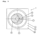
- FIG. 3 shows the device as described in figure 2 from top view.
- the cross-sectional area of the segment 4 containing the magnetorheological material 5 is smaller than the cross-sectional area of the plates 9 and 10.
- the electromagnetic coil encloses the segment 4 by its ring-like shape.
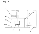
- FIG 4 shows another special embodiment according to present invention.
- the actively controllable unit 2 consists of an electric motor 7 in connection with an excenter 8, which is directly connected to the plate 9.
- the plates 9 and 10 are built of an electrically conductive material. Both plates 9 and 10 serve as electrodes which can be powered by a high voltage supply, which is part of the unit for generating the electric field 6. Both plates 9 and 10 are separated by an electrically insulating material (insulator) 11.
- the electrorheological material 5 which is included in the segment 4, can be controlled by the strength of the electric field being applied to the plates 9 and 10.
- the plates 9 and 10 are movable with respect to each other.
- the vibrating object 1' can be connected by force to the plate 10.
Landscapes
- Engineering & Computer Science (AREA)
- General Engineering & Computer Science (AREA)
- Mechanical Engineering (AREA)
- Apparatuses For Generation Of Mechanical Vibrations (AREA)
- Vibration Prevention Devices (AREA)
Abstract
Description
- Present invention relates to a device for reducing vibrations of a vibrating object as well as a method for reducing vibrations, wherein the perturbing vibrations are reduced drastically by induction of counter-forces. In general, vibrations of equal frequency (counter-vibration) as the perturbing vibration are generated. The force generated by the counter-vibration acts onto the vibrating object, whose amplitude of vibration is to be reduced. The phasing of the counter-vibration is antipodal to the vibration to be reduced, preferably the force of the generated counter-vibration is greater than the force being necessary for compensation of the perturbing vibration. The transfer of the force of the counter-vibration onto the vibrating object is affected by means of a magnetorheological or electrorheological material, whereby the absolute value of the transmitted force is adjusted by the magnitude of an applied magnetical or electric field. With increasing strength of the magnetical or electric field, the magnetorheological or electrorheological material is stiffened increasingly. With optimal adjustments of the strength of the electric or magnetic field, the transmitted force equals the perturbing force and the perturbing vibration is compensated.
- Magnetorheological materials, especially fluids, are suspensions of magnetically polarizable particles in a carrier substance, especially a carrier liquid, whose modulus of rigidity, shear modulus, Young's modulus and/or the yield stress can be changed in an electric or magnetic field quickly and reversibly. In analogy, electrorheological materials, especially electrorheological fluids, are suspensions of electrically polarizable particles in a non-conducting carrier liquid, whose modulus of rigidity, the shear modulus, the Young's modulus and/or the yield stress can be changed quickly and reversibly in an electric field. Both classes of materials therefore offer an ideal basis for an adaptive force-transfer wherein the force to be transferred is controlled via the external field.
- Devices for reducing vibrations in which the force for reduction of the vibration is generated by a magnetorheological or electrorheological fluid in a magnetic or an electric field, respectively, are already known. The advantage of such devices is the short reaction time towards a change in field intensity. For example, magnetorheological devices for reducing vibrations are known from the
EP 1 270 988 B1DE 101 43 980 A1 . - However, the devices for reducing vibrations known from the prior art are adaptive damping-systems on basis of magnetorheological or electrorheological fluids, in which the damping-force can be controlled by the magnetic or electric field intensity, respectively. The disadvantage of these systems is that only passive forces can be generated.
- It is therefore an object of present invention to provide a system for reducing vibrations, which allows providing active forces for reducing vibrations of a vibrating object. Furthermore, it is an object of present invention to provide a method for reducing vibrations for a vibrating object, wherein the method guarantees an effective reducing of vibrations.
- These objects are accomplished by the features of the independent claims. The further dependent claims describe advantageous embodiments.
- According to the invention, there is provided a device for reducing vibrations of a vibrating object, wherein the device comprises:
- a) at least one actively controllable unit for generating a temporarily varying force,
- b) at least one force transmitting unit which comprises at least one segment which contains at least one electrorheological and/or magnetorheological material,
- c) at least one unit for generating an electric and/or magnetic field,
- In contrast to the devices described in prior art, the device for reducing vibrations according to the invention transfers an externally generated force via a magnetorheological or electrorheological material in order to meet individual needs for reducing troublesome vibrations by inducing an actively generated counter-force. The magnetorheological or electrorheological material thereby acts as a coupling-medium, the consistence of which can be controlled via a magnetic or electric field.
- Therefore, it is preferred if the at least one actively controllable unit is at least one device for generating a force that varies in one, two and/or three dimensions. Especially, the at least one actively controllable unit comprises at least one motor, preferably a motor selected from the group consisting of electric motors, combustion motors, electromagnetic actuators, voice coils and/or other actuators. In such, the actively controllable unit is not limited as far as it is assured that the device allows a generation of a varying force. In a further embodiment, two or more devices are present for generating the varying force.
- In an especially preferred embodiment, the motor is connected by force to an excentric for conversion of a circular motion into stroke movement, in such that the excentric can be agitated by the motor.
- A further advantageous embodiment provides that the at least one force transmitting unit comprises two elements which are movable with respect to each other, border the force transmitting unit and enclose the at least one segment, wherein the elements preferably are aligned parallelly. These elements preferably exhibit two surfaces, which are parallel aligned. In such, the shape of the two elements is not limited in any respect, yet it is preferred, if the two elements are selected from the group consisting of plates, cuboids, segments, ovoid shaped elements, spherical shells and/or cones, wherein parallel plates are especially preferred.
- Moreover, it is advantageous, if the two elements are movable in one, two and/or three dimensions with respect to each other. In such, the device is separated into two sections which are movable with respect to each other, wherein these two sections are bordered by the two elements.
- Herein, it is preferred, if one element is connected by force with the at least one device for generating the varying force, whereas the other element is connectable by force to the vibrating object. This embodiment enables a direct force transmittal between the at least one actively controllable unit and the vibrating object.
- Furthermore, it is a special embodiment of present invention that the segment has a cross-sectional area which is dimensioned smaller than the cross-sectional area of the elements. In this embodiment, in projection onto the cross-sectional area of the segment, the elements are larger and overlap the segment (see also
fig. 3 and description). - It is especially preferred, if the at least one unit for generating a magnetic or electric field is at least partially located within the at least one force transmitting unit. It is hereby understood that the unit for generating the field can be composed of any of the parts of the force transmitting unit, e.g. the elements. Alternatively, the unit can be composed of additional parts, which are at least partially located inside the force transmitting unit. Those embodiments guarantee an extremely compact assembly of the device.
- A further advantageous embodiment provides that the unit for generating an electric and/or magnetic field is located in direct proximity to the segment, so that it is guaranteed that the segment is permeated by the electric and/or magnetic field. This feature is accomplished for example by aligning the unit around the segment, especially in a ring-like assembly like an electromagnetic coil or, alternatively, by a sandwich-like built-up, wherein the segment is aligned between the components for generating an electric and/or magnetic field like e.g. a pair of electrode plates.
- Furthermore, it is preferred if at least one control system for controlling the actively controllable unit and/or at least one control system for controlling the at least one unit for generating a magnetic and/or electric field is comprised. This control system for example can comprise any electronic switching circuits or electronic guidance systems, which provide a direct response to the actively controllable unit and/or the unit for generating a field, thereby enabling an active control to the transmitted force from the actively controllable unit towards the vibrating object.
- Preferably, the device comprises at least one sensor for registration of the amplitude, frequency and/or phase of the vibration of the vibrating object. This enables the device to be actively controlled dependent on the vibration of the vibrating object. The data derived from this sensor, e.g. the character of the vibration, can be used to generate a feedback and thus allows an active control of the controllable device and/or the unit for generating a magnetic and/or electric field. Therefore, it is especially preferred if the at least one control system for controlling the actively controllable unit and/or at least one control system for controlling the at least one unit for generating a magnetic and/or electric field is coupled to the at least one sensor.
- According to one especially preferred magnetic embodiment of the invention, the unit for generating a magnetic field comprises at least one electromagnetic coil. The electromagnetic coil thereby is powered by at least one regulable electric power supply.
- Preferably, the electromagnetic coil is located within the space between the two elements.
- It is further advantageous if the at least one electromagnetic coil is ring-like and aligned concentrically around the at least one segment. This embodiment enables a strong injection of the generated magnetic field into the at least one segment and thereby into the magnetorheological material, since the electromagnetic coil and the segment are in direct vicinity with respect to each other.
- Furthermore, it is preferred that the force transmitting unit, especially the two elements, comprises at least one ferromagnetic material in the magnetic circuit, which preferably is selected from the group consisting of iron, cobalt, nickel, ferromagnetic steel, alloys thereof and/or transformator sheets. This embodiment provides that any of the parts of the force transmitting unit can be made of a ferromagnetic material. According to the invention, transformator sheets are defined as laminated sheets, which are known to the person skilled in the art. The usage of transformator sheets, for example as materials for the two elements, avoids the generation of eddy currents.
- It is especially preferred, that the magnetic circuit in the device (1) is at least partially built by a material that exhibits a relative permeability µr > 10, preferably > 100, especially preferred > 1000 and/or a saturation magnetisation of > 0.5 T, preferably > 1 T, especially preferred > 1.5 T.
- Furthermore, it is advantageous if at least one permanent magnet is included in the magnetic circuit. This feature concerns an embodiment of the invention, wherein for example the two elements are permanently magnetized so that a constant magnetic field is present. This constant magnetic field permanently affects the rheological properties of the magnetorheological material, being included in the segment. Thereby, the magnetorheological material exhibits a base rigidity, which further can be effected by superposing the permanent magnetic field with a varying magnetic field generated by the electromagnetic coil. Therefore, the special advantage of this embodiment is that less electric power is needed in order to modulate the rheological properties of the magnetorheological material in such that a certain rigidity or stiffness is reached.
- The magnetorheological materials are not limited in any respect, yet it is preferred, if the material is selected from the group consisting of magnetorheological (MR) fluids, MR elastomeres, MR thermoplastic elastomeres, MR gels and/or MR foams.
- In another especially preferred electric embodiment of present invention, the at least one unit for generating an electric field comprises two electrodes. In such, it is provided that any of the parts of the at least one unit for generating an electric field can be shaped as two electrodes, but alternatively, it is also possible that two separate electrodes are included in this unit. It is especially advantageous, if the electrodes are composed by the two elements. These two electrodes are powered by at least one regulable electric power supply. The electrodes are separated spatially, in such that it is guaranteed that high voltages can be applied to the electrodes but no electric breakdown occurs.
- Again, the electrorheological materials are not limited in any way, but are preferably selected from the group consisting of electrorheological (ER) fluids, ER elastomeres, ER thermoplastic elastomeres, ER gels and/or ER foams.
- Furthermore, present invention provides a method for reducing vibrations of a vibrating object, wherein a varying force is generated by at least one actively controllable unit and is transferred to the vibrating object via at least one electrorheological and/or magnetorheological material, characterized in that the varying force is adjusted by modulation of the at least one electrorheological and/or magnetorheological material, in such that the varying force counteracts at least partially the force resulting from the vibration of the vibrating object. It is a special advantage of the method according to the invention that relatively large forces for damping vibrations can be generated and transmitted to the vibrating object. The use of ER or MR materials opens a wide range of possible applications.
- Preferably, the force being generated by the at least one actively controllable device is varied in its magnitude and/or in its direction, especially, the force is varied in one, two and/or three dimensions.
- Over more, it is advantageous, if the at least one device generates the force with a frequency, which at least temporarily matches the frequency of the vibration of the vibrating object, wherein it is further preferred that the phase of the generated force is at least temporarily and/or partially antipodal to the phase of the vibration of the vibrating object. By this feature, perturbing vibrations of the object can be reduced to virtually zero.
- E.g. the varying force can be generated by two or more units. The combined use of more than one unit brings additional advantageous effects:
- 1) Two or more devices rotating at different frequencies compose and approximate an arbitrary exciting waveform, which according to Fourier can be expressed by series of simpler sinusoidal waves, i.e. a square wave can be composed by the fundamental frequency plus the 3rd harmonic running in a second "vibraspin", i.e. the second device.
- 2) The use of two or more devices enables the geometrical focus to be chosen and varied by applying the full biaxial damping force, i.e. two "vibraspin" placed radially opposed around a spindle can be driven in order to focus the action exactly near the TCP (tool central point).
- This embodiment can be achieved in that each of the at least two units (2) generates varying forces, which are superimposed thus resulting in the varying force, which is transferred to the vibrating object (1'). In such, these embodiments enable special variations of the resulting force in time and/or in space.
- In another preferred embodiment of the method according to the invention, the varying force which is generated by the at least one actively controllable device results from the rotation of an excentric and/or the agitation of a motor, preferably a motor selected from the group consisting of electric motors, combustion motors, electromagnetic actuators and/or voice coils. This embodiment allows the generation of effectively large harmonic forces with very simple technical means.
- Preferably, the excentric is actuated by a motor, preferably an electromotor.
- For providing a good match of the generated force and the vibration of the vibrating object, it is preferred if the speed of the motor, especially of the electromotor is controlled as a function of the frequency of the vibration of the vibrating object so that the frequency of the unbalance generated by the rotation of the excentric at least temporarily, preferably virtually at any time, matches the frequency of the vibration of the vibrating object.
- Herein, it is preferred, if the motor, especially the electromotor, is controlled in such that the phase of the unbalance generated by the rotation of the excentric at least temporarily and/or partially is antipodal to the phase of the vibration of the vibrating object, i.e. the generated force can be described as counterforce to the force which results from the vibration.
- Advantageously, the magnitude of the resulting varying force at least temporarily is adjusted at least to the same magnitude or larger than the magnitude of the force resulting from the vibration of the vibrating object. This is achieved by adjusting the weight of the excenter, the rotation speed of the excenter and/or the stiffness or rigidity of the ER or MR material. The special conditions for the afore-mentioned parameters can easily be determined by the person skilled in the art and of course depend on the characteristics of the vibration and/or the vibrating object.
- Furthermore, it is preferred, if the adjusting of the magnitude of the force is achieved by modulation of at least one rheological property, preferably the shear modulus and/or the compression modulus of the at least one electrorheological and/or magnetorheological material.
- Especially, the at least one rheological property, e.g. the shear modulus, is controlled by application of an electric and/or magnetic field, depending on the nature of the material, i.e. ER or MR material. It is possible that the field intensity of the electric and/or magnetic field is held constant, varied and/or a constant field is superposed with a varying field.
- The method according to the invention preferably is carried out with a device described in the foregoing.
- Possible uses of the device as well as the method according to the invention are provided with claims 43 and 44.
- The present invention is described in more detail in the subsequent description and the figures. However, the following description is not to be understood to limit the present invention in any respect.
- Figure 1
- shows a general assembly of a
device 1 ac- cording to present invention, which is cou- pled to a vibrating object 1'. - Figure 2
- shows a special embodiment of present in- vention, wherein the
device 1 comprises a magnetic field generating unit, containing in this case an electromagnetic coil. - Figure 3
- depicts another perspective view (from above) of the device displayed in
figure 2 . - Figure 4
- describes the electric embodiment of the
device 1, which comprises two electrodes for generating an electric field. - The generation and transmission of the counter-force generated by the extinction-oscillation (
figure 1 , F_T) onto the force, generated by the vibration to be extinguished (figure 1 , F) is achieved according to the invention by thedevice 1, wherein a magnetorheological or anelectrorheological material 5 in asegment 4 is comprised between two elements with parallelly aligned surfaces, which are movable relatively to each other. The magnetic or electric flux-lines run perpendicular to the surfaces. During the relative movement of the surfaces, the magnetorheological or electrorheological material is sheared (shear modulus). The strength of the mechanical coupling and thus the force to be transferred to the vibrating object 1' can be adjusted by the magnetic or electric field strength, which is generated by the unit 6 (which in this case is composed by theplates 9,10). Other possibilities of the transmittance of the force are the adjusting of the flow modulus, the squeeze modulus or mixed forms of movement of the named three modi together, depending on the nature of the ER or MR material to be used. Furthermore, one, two or three dimensional oscillations or vibrations can be generated by thedevice 2 and transferred via the magnetorheological or electrorheological material, which is included in theforce transmitting unit 3. - A simple possibility to generate the counter-vibration is to use an electromotor, which drives a rotating mass with an unbalance (excenter). Thus, a relative small motor with small power consumption can generate relatively large forces (centrifugal forces). Because of the circular nature of the thus generated counter-vibration, also vibrations with amplitudes in two-dimensions can be compensated, these vibrations for example can occur during rotations of arbors of a machine or during stroke movements of lobes, pistons or plungers and the like.
- The magnetic or electric field for stiffening the magnetorheological or electrorheological material usually is generated via an electromagnet with a coil or via electrodes, wherein the intensity of electric current in the coil defines the magnetic field strength or the flux density, whereas the voltage being applied to the electrodes defines the electric field strength, respectively. Due to integration of a permanent magnet into the magnetic circle, which generates the magnetic field for the magnetorheological material, a base force to be transferred can be generated without an electric current in the coil, i.e. without usage of electric energy, by permanently influencing the rheologic properties (i.e. stiffening) of the MR material.
- Special embodiments of the device for reducing vibrations according to the invention provide that the magnetorheological material is an magnetorheological fluid (MRF), a magnetorheological gel (MRG), a magnetorheological elastomer (MRE) or a magnetorheological foam (MRFo). A MRG is a material, which in contrast to an MRF is soft, but not fluid. In analogy to an MRF, it can be deformed in any way irreversibly and be stiffened in a magnetic field. An MRE is a chemically cross-linked material, which therefore has a given shape from which it can be deformed reversibly only in limited ways. An MRFo is an elastomeric foam, whose pores are filled with an MRF. In analogy to an MRE, also an MRFo has a defined form, from which it can be deformed reversibly in only limited ways. Likewise to the forgoing, instead of magnetorheological material, also electrorheological material, such as electrorheological fluids (ERF), electrorheological gels (ERG), electrorheological elastomers (ERE) or electrorheological foams (ERFo) can be used.
- Possible uses of the device according to the invention are electric controllable devices for reducing vibrations in which a distracting vibration is actively reduced. This is especially interesting for motors or engines with rotating parts, because here, due to the number of revolutions per minute, a special frequency of vibration is defined. The active device for reducing vibrations therefore is to be tuned to this frequency. Examples are engines in automobiles and ships, rotating drums in laundry machines as well as rotating spindles, for example in machine tools, such as milling, drilling or turning machines. Further fields of applications are the reducing of unbalances with rotational movements. Also, the compensation of one-dimensional vibrations resulting from pistons and the like is possible.
- In
figure 1 , the principle build-up of thedevice 1 according to the invention is depicted. Hereby, thedevice 1 comprises one activelycontrollable unit 2, which generates a temporarily varying force (F_T), which is connected by force to theforce transmitting unit 3. Theforce transmitting unit 3 herein comprises the unit for generating an electric and/ormagnetic field 6, and also asegment 4, which contains an electrorheological and/ormagnetorheological material 5. In this embodiment, the bordering elements of theforce transmitting unit 3 act as the parts which guide the electric and/or magnetic field to the ER or MR material. Theforce transmitting unit 3 is connected to the vibrating object 1' with its side opposite to that which is connected to thedevice 2. The force generated by thedevice 2 is transferred to theforce transmitting unit 3, which comprises two movable parts, in this special case consisting of the elements of the unit for generating thefield 6 and guiding the field to the ER or MR material. By adjustment of the electric and/or magnetic field, the stiffness of the electrorheological and/ormagnetorheological material 5 is controlled and thereby also the transmittance of the force (F_T) generated by thedevice 2 onto the vibrating object 1'. The generated force (F_T) is antipodal to the force (F) generated by the vibration of the vibrating object 1'. -
Figure 2 andfigure 3 show one special embodiment according to the invention, wherein thedevice 1 comprises an activelycontrollable unit 2, which consists of anelectric motor 7 and an therebyagitated excenter 8. Thisexcenter 8 is directly fixed to theplate 9, which is movable with respect to theplate 10. Bothplates force transmitting unit 3. Preferably they are made of a magnetic flux guiding material. In this embodiment, the unit for generating a field is anelectromagnetic coil 6, which is ring-like and aligned around asegment 4, which contains amagnetorheological material 5. The stiffness of themagnetorheological material 5 and thus the coupling of the force being generated by thedevice 2 to theplate 10 can be controlled by adjusting the magnetic field strength being generated by theelectromagnetic coil 6. The vibrating object 1' (not shown) can be connected to theplate 10.Figure 3 shows the device as described infigure 2 from top view. Here, it becomes obvious, that the cross-sectional area of thesegment 4 containing themagnetorheological material 5 is smaller than the cross-sectional area of theplates segment 4 by its ring-like shape. -
Figure 4 shows another special embodiment according to present invention. Again, as already described withfigures 2 and3 , the activelycontrollable unit 2 consists of anelectric motor 7 in connection with anexcenter 8, which is directly connected to theplate 9. In this special case, theplates plates electric field 6. Bothplates figures 2 and3 , theelectrorheological material 5, which is included in thesegment 4, can be controlled by the strength of the electric field being applied to theplates plates plate 10.
Claims (44)
- Device (1) for reducing vibrations of a vibrating object (1'), wherein the device (1) comprises:a) at least one actively controllable unit (2) for generating a temporarily varying force,b) at least one force transmitting unit (3) which comprises at least one segment (4) which contains at least one electrorheological and/or magnetorheological material (5),c) at least one unit (6) for generating an electric and/or magnetic field,characterized in that the unit (2) is connected by force to the at least one force transmitting unit (3).
- Device (1) according to claim 1, characterized in that the at least one unit (2) is at least one device for generating a force that varies in magnitude and/or direction.
- Device (1) according to one of the preceding claims, characterized in that the at least one unit (2) is at least one device for generating a force that varies in one, two and/or three dimensions.
- Device (1) according to one of the preceding claims, characterized in that the at least one unit (2) comprises at least one motor (7), preferably a motor selected from the group consisting of electric motors, combustion motors, electromagnetic actuators, voice coils and/or any other kind of actuators.
- Device (1) according to the preceding claim, characterized in that the at least one motor (7) is connected by force to an excentric (8) for conversion of a circular motion into stroke movement, in such that the excentric (8) can be agitated by the motor (7).
- Device (1) according to one of the preceding claims, characterized in that the at least one force transmitting unit (3) comprises two elements (9, 10) which are movable with respect to each other, border the force transmitting unit (3) and enclose the at least one segment (4), wherein the elements preferably are aligned parallel.
- Device (1) according to the preceding claim, characterized in that two elements (9, 10) are selected from the group consisting of plates, cuboids, segments, ovoid shaped elements, spherical shells and/or cones.
- Device (1) according to the preceding claim, characterized in that the elements (9, 10) are movable in one, two and/or three dimensions.
- Device (1) according to one of the claims 6 to 8, characterized in that the element (9) is connected by force with the at least one unit (2), whereas the element (10) is connectable by force to the vibrating object (1').
- Device (1) according to one of the claims 6 to 9, characterized in that the segment (4) has a cross-sectional area which is dimensioned smaller than the cross-sectional area of the elements (9, 10).
- Device (1) according to one of the preceding claims, characterized in that the at least one unit (6) is located within the at least one force transmitting unit (3).
- Device (1) according to one of the preceding claims, characterized in that the unit (6) for generating an electric and/or magnetic field is located in direct proximity to the segment (4), so that it is guaranteed that the segment (4) is permeated by the electric and/or magnetic field.
- Device (1) according to one of the preceding claims, characterized in that at least one control system for controlling the unit (2) and/or at least one control system for controlling the at least one unit (6) is comprised.
- Device (1) according to one of the preceding claims, characterized in that it comprises at least one sensor for registration of the amplitude, frequency and/or phase of the vibration of the vibrating object (1').
- Device (1) according to one of the claims 13 and 14, characterized in that the at least one control system for controlling the unit (2) and/or at least one control system for controlling the at least one unit (6) is coupled to the at least one sensor for registration of the amplitude, frequency and or phase of the vibration of the vibrating object (1').
- Device (1) according to one of the preceding claims, characterized in that the at least one unit (6) comprises at least one electromagnetic coil.
- Device (1) according to the preceding claim, characterized in that the at least one unit (6) further comprises at least one regulable electrical power supply for powering the electromagnetic coil.
- Device (1) according to one of the claims 16 or 17, characterized in that the at least one electromagnetic coil is located between the elements (9, 10).
- Device (1) according to one of the claims 16 to 18, characterized in that the at least one electromagnetic coil is ring-like and aligned concentrically around the at least one segment (4).
- Device (1) according to one of the claims 16 to 19, characterized in that the force transmitting unit (3), especially the at least one element (9) and/or (10) is part of a magnetic circuit system and comprises at least one ferromagnetic material, which preferably is selected from the group consisting of iron, cobalt, nickel, ferromagnetic steel and/or alloys thereof and/or transformator sheets.
- Device (1) according to one of the claims 16 to 20, characterized in that the magnetic circuit in the device (1) is at least partially built by a material which has a relative permeability µr > 10, preferably > 100, especially preferred > 1000 and/or a saturation magnetisation of > 0.5 T, preferably > 1 T, especially preferred > 1.5 T.
- Device (1) according to claims 16 to 21, characterized in that the magnetic circuit system comprises at least one permanent magnet.
- Device (1) according to one of the preceding claims, characterized in that the at least one magnetorheological material (5) is selected from the group consisting of magnetorheological (MR) fluids, MR elastomers, MR thermoplastic elastomers, MR gels and/or MR foams.
- Device (1) according to one of the claims 1 to 15, characterized in that the at least one unit (6) comprises two electrodes, which preferably are composed of the elements (9) and (10).
- Device (1) according to the preceding claim, characterized in that the unit (6) further comprises at least one regulable electrical power supply for powering the electrodes.
- Device (1) according to one of the claims 24 to 25, characterized in that the at least one electrorheological material (5) is selected from the group consisting of electrorheological (ER) fluids, ER elastomers, ER thermoplastic elastomers, ER gels and/or ER foams.
- Method for reducing vibrations of a vibrating object (1'), wherein a varying force is generated by at least one actively controllable unit (2) and is transferred to the vibrating object (1') via at least one electrorheological and/or magnetorheological material (5), characterized in that the varying force is adjusted by modulation of the at least one electrorheological and/or magnetorheological material (5), in such that the varying force counteracts at least partially the force resulting from the vibration of the vibrating object (1').
- Method according to claim 27, characterized in that the force being generated by the at least one unit (2) is varied in its magnitude and/or in its direction in transmission to the vibrating object (1').
- Method according to one of the claims 27 or 28, characterized in that the force being generated by the at least one unit (2) is varied in one, two and/or three dimensions.
- Method according to one of the claims 27 to 29, characterized in that the at least one unit (2) generates the force with a frequency, which at least temporarily matches the frequency of the vibration of the vibrating object (1').
- Method according to one of the claims 27 to 30, characterized in that the at least one unit (2) generates the force with a phase that at least temporarily and/or partially is antipodal to the phase of the vibration of the vibrating object (1').
- Method according to claims 27 to 31, characterized in that two or more units (2) generate the varying force.
- Method according to the preceding claim, characterized in that each of the at least two units (2) generates varying forces, which are superimposed thus resulting in the varying force, which is transferred to the vibrating object (1').
- Method according to one of the claims 27 to 33, characterized in that the varying force being generated by the unit (2) results from the rotation of an excentric (8) and/or the agitation of a motor (7), preferably an motor selected from the group consisting of electric motors, combustion motors, electromagnetic actuators, voice coils and/or any other kind of actuators.
- Method according to the preceding claim, characterized in that the excentric (8) is actuated by a motor (7), preferably an electromotor.
- Method according to the preceding claim, characterized in that the speed of the motor, especially of the electromotor is controlled as a function of the frequency of the vibration of the vibrating object (1') so that the frequency of the unbalance generated by the rotation of the excentric (8) at least temporarily matches the frequency of the vibration of the vibrating object (1').
- Method according to one of the claims 35 to 36, characterized in that the motor (7), especially the electromotor, is controlled in such that the phase of the unbalance generated by the rotation of the excentric (8) at least temporarily and/or partially is antipodal to the phase of the vibration of the vibrating object (1').
- Method according to one of the claims 35 to 36, characterized in that the magnitude of the resulting varying force at least temporarily is adjusted at least to the same magnitude or larger than the magnitude of the force resulting from the vibration of the vibrating object (1').
- Method according to preceding claim, characterized in that the adjusting of the magnitude of the force is achieved by modulation of at least one rheological property, preferably the shear modulus, the compression modulus and/or the Young's modulus of the at least one electrorheological and/or magnetorheological material (5).
- Method according to the preceding claim, characterized in that the at least one rheological property is controlled by application of an electric and/or magnetic field.
- Method according to the preceding claim, characterized in that the field intensity of the electric and/or magnetic field is held constant, varied and/or a constant field is superposed with a varying field.
- Method according to one of the claims 27 to 41, characterized in that the method is carried out by a device according to one of the claims 1 to 26.
- Use of the device according to one of the claims 1 to 26 for reducing vibrations and/or damping of unbalances, preferably of motors, turning drums, barrels, cylinders, reels, rolls, spindles and/or rotating parts.
- Use of the method according to one of the claims 27 to 42 for reducing vibrations, damping and/or compensation of unbalances or unbalanced masses, preferably of motors, turning drums, barrels, cylinders, reels, rolls, spindles and/or rotating parts.
Priority Applications (2)
| Application Number | Priority Date | Filing Date | Title |
|---|---|---|---|
| EP08004199A EP2098747B1 (en) | 2008-03-06 | 2008-03-06 | Active vibration-extinguisher containing magneto or electrorheological fluids, method for reducing vibrations and uses thereof |
| US12/395,770 US20100307877A1 (en) | 2008-03-06 | 2009-03-02 | Active vibration-extinguisher containing magneto- or electrorheological fluids, method for reducing vibrations and uses thereof |
Applications Claiming Priority (1)
| Application Number | Priority Date | Filing Date | Title |
|---|---|---|---|
| EP08004199A EP2098747B1 (en) | 2008-03-06 | 2008-03-06 | Active vibration-extinguisher containing magneto or electrorheological fluids, method for reducing vibrations and uses thereof |
Publications (2)
| Publication Number | Publication Date |
|---|---|
| EP2098747A1 true EP2098747A1 (en) | 2009-09-09 |
| EP2098747B1 EP2098747B1 (en) | 2012-06-06 |
Family
ID=39627840
Family Applications (1)
| Application Number | Title | Priority Date | Filing Date |
|---|---|---|---|
| EP08004199A Not-in-force EP2098747B1 (en) | 2008-03-06 | 2008-03-06 | Active vibration-extinguisher containing magneto or electrorheological fluids, method for reducing vibrations and uses thereof |
Country Status (2)
| Country | Link |
|---|---|
| US (1) | US20100307877A1 (en) |
| EP (1) | EP2098747B1 (en) |
Cited By (5)
| Publication number | Priority date | Publication date | Assignee | Title |
|---|---|---|---|---|
| US8303110B1 (en) | 2011-09-11 | 2012-11-06 | Google Inc. | Nose pads for a wearable device having an electrically-controllable hardness |
| CN104613124A (en) * | 2015-02-04 | 2015-05-13 | 吉林大学 | Double-piston electro-rheological shock absorber |
| CN113757298A (en) * | 2021-09-09 | 2021-12-07 | 哈尔滨工业大学 | Piston type magnetorheological elastomer dynamic vibration absorber with shearing-compression mixing effect |
| CN115773329A (en) * | 2022-12-01 | 2023-03-10 | 南京理工大学 | A magneto-rheological grease shock absorber with independent piston control |
| CN120007746A (en) * | 2025-03-20 | 2025-05-16 | 南京航空航天大学 | Liquid-elastic active vibration isolation device and control method |
Families Citing this family (8)
| Publication number | Priority date | Publication date | Assignee | Title |
|---|---|---|---|---|
| KR101724747B1 (en) * | 2011-11-23 | 2017-04-10 | 현대자동차주식회사 | Variable differential mount system applied Magnetorheological Elastomer |
| US9016318B2 (en) * | 2012-01-24 | 2015-04-28 | GM Global Technology Operations LLC | Magnetorheological fluid-based device and method for use |
| US20170341739A1 (en) * | 2014-12-16 | 2017-11-30 | Sikorsky Aircraft Corporation | Variable amplitude force generator |
| RU2611691C1 (en) * | 2015-11-18 | 2017-02-28 | Федеральное государственное бюджетное образовательное учреждение высшего профессионального образования "Московский государственный технический университет имени Н.Э. Баумана" (МГТУ им. Н.Э. Баумана) | Active antivibration platform based on magnetorheological elastomers |
| KR102226692B1 (en) * | 2019-09-02 | 2021-03-11 | 공주대학교 산학협력단 | Vibration damping device and method of precision stage using magnetic force |
| CN112245846B (en) * | 2020-10-21 | 2021-11-23 | 浙江旺潮科技有限公司 | Magnetic early warning formula fire control shower nozzle is used in wisdom fire control |
| EP4402393A1 (en) * | 2021-09-15 | 2024-07-24 | BAE SYSTEMS plc | Resonator, resonator array, vibration control system and method |
| CN115681391B (en) * | 2022-09-27 | 2024-05-10 | 重庆邮电大学 | A magnetorheological elastomer vibration isolation system with self-sensing, self-powered and adaptive control |
Citations (11)
| Publication number | Priority date | Publication date | Assignee | Title |
|---|---|---|---|---|
| US3548972A (en) * | 1969-03-18 | 1970-12-22 | Kaman Aerospace Corp | Vibration absorber with rotating mass |
| US4742998A (en) * | 1985-03-26 | 1988-05-10 | Barry Wright Corporation | Active vibration isolation system employing an electro-rheological fluid |
| EP0338933A1 (en) * | 1988-04-20 | 1989-10-25 | Societe De Mecanique Magnetique | Active magnetically suspended vibration device controlled in three axes |
| US4963804A (en) * | 1989-07-10 | 1990-10-16 | Westinghouse Electric Corp. | Apparatus and method for reducing vibration of rotating machinery |
| US20020104950A1 (en) * | 2000-11-27 | 2002-08-08 | Takehiko Mayama | Active vibration suppression apparatus, control method therefor, and exposure apparatus having active vibration suppression apparatus |
| US20020123403A1 (en) * | 2001-02-27 | 2002-09-05 | Welsh William Arthur | High output force actuator for an active vibration control system |
| DE10143980A1 (en) | 2001-09-07 | 2003-03-27 | Bosch Rexroth Ag | Magneto-rheological damper has working space for rheological fluid defined by annular space between piston and cylinder extending at angle to piston axis |
| DE10302468B3 (en) * | 2003-01-23 | 2004-06-03 | Wegu Gummi- Und Kunststoffwerke Gmbh & Co. Kg | Vibration absorber with adjustable frequency to damp vibrations of machines has numerous separate pre-magnetized metal particles in elastomer |
| US20040222755A1 (en) * | 2003-05-08 | 2004-11-11 | Borz Fariborzi | Antivibration apparatus and vehicle equipped with such antivibration apparatus |
| US20050075210A1 (en) * | 2003-10-01 | 2005-04-07 | Frederickson Kirk Charles | Harmonic force generator for an active vibration control system |
| EP1270988B1 (en) | 2001-06-19 | 2005-07-27 | Delphi Technologies, Inc. | Magnetorheological fluid damper |
Family Cites Families (5)
| Publication number | Priority date | Publication date | Assignee | Title |
|---|---|---|---|---|
| US5396973A (en) * | 1991-11-15 | 1995-03-14 | Lord Corporation | Variable shock absorber with integrated controller, actuator and sensors |
| US5398785A (en) * | 1993-01-11 | 1995-03-21 | Regeants Of The University Of California | Semiactive control apparatus for damping vibrations of a body |
| KR100399812B1 (en) * | 1994-10-11 | 2003-12-01 | 가부시키가이샤 니콘 | Vibration Prevention Device for Stage |
| US6622995B2 (en) * | 2001-05-16 | 2003-09-23 | Delphi Technologies, Inc. | Hydraulic mount with magnetorheological fluid |
| US6886819B2 (en) * | 2002-11-06 | 2005-05-03 | Lord Corporation | MR fluid for increasing the output of a magnetorheological fluid damper |
-
2008
- 2008-03-06 EP EP08004199A patent/EP2098747B1/en not_active Not-in-force
-
2009
- 2009-03-02 US US12/395,770 patent/US20100307877A1/en not_active Abandoned
Patent Citations (11)
| Publication number | Priority date | Publication date | Assignee | Title |
|---|---|---|---|---|
| US3548972A (en) * | 1969-03-18 | 1970-12-22 | Kaman Aerospace Corp | Vibration absorber with rotating mass |
| US4742998A (en) * | 1985-03-26 | 1988-05-10 | Barry Wright Corporation | Active vibration isolation system employing an electro-rheological fluid |
| EP0338933A1 (en) * | 1988-04-20 | 1989-10-25 | Societe De Mecanique Magnetique | Active magnetically suspended vibration device controlled in three axes |
| US4963804A (en) * | 1989-07-10 | 1990-10-16 | Westinghouse Electric Corp. | Apparatus and method for reducing vibration of rotating machinery |
| US20020104950A1 (en) * | 2000-11-27 | 2002-08-08 | Takehiko Mayama | Active vibration suppression apparatus, control method therefor, and exposure apparatus having active vibration suppression apparatus |
| US20020123403A1 (en) * | 2001-02-27 | 2002-09-05 | Welsh William Arthur | High output force actuator for an active vibration control system |
| EP1270988B1 (en) | 2001-06-19 | 2005-07-27 | Delphi Technologies, Inc. | Magnetorheological fluid damper |
| DE10143980A1 (en) | 2001-09-07 | 2003-03-27 | Bosch Rexroth Ag | Magneto-rheological damper has working space for rheological fluid defined by annular space between piston and cylinder extending at angle to piston axis |
| DE10302468B3 (en) * | 2003-01-23 | 2004-06-03 | Wegu Gummi- Und Kunststoffwerke Gmbh & Co. Kg | Vibration absorber with adjustable frequency to damp vibrations of machines has numerous separate pre-magnetized metal particles in elastomer |
| US20040222755A1 (en) * | 2003-05-08 | 2004-11-11 | Borz Fariborzi | Antivibration apparatus and vehicle equipped with such antivibration apparatus |
| US20050075210A1 (en) * | 2003-10-01 | 2005-04-07 | Frederickson Kirk Charles | Harmonic force generator for an active vibration control system |
Cited By (6)
| Publication number | Priority date | Publication date | Assignee | Title |
|---|---|---|---|---|
| US8303110B1 (en) | 2011-09-11 | 2012-11-06 | Google Inc. | Nose pads for a wearable device having an electrically-controllable hardness |
| CN104613124A (en) * | 2015-02-04 | 2015-05-13 | 吉林大学 | Double-piston electro-rheological shock absorber |
| CN104613124B (en) * | 2015-02-04 | 2016-07-13 | 吉林大学 | A kind of double-piston current transformation vibration damper |
| CN113757298A (en) * | 2021-09-09 | 2021-12-07 | 哈尔滨工业大学 | Piston type magnetorheological elastomer dynamic vibration absorber with shearing-compression mixing effect |
| CN115773329A (en) * | 2022-12-01 | 2023-03-10 | 南京理工大学 | A magneto-rheological grease shock absorber with independent piston control |
| CN120007746A (en) * | 2025-03-20 | 2025-05-16 | 南京航空航天大学 | Liquid-elastic active vibration isolation device and control method |
Also Published As
| Publication number | Publication date |
|---|---|
| EP2098747B1 (en) | 2012-06-06 |
| US20100307877A1 (en) | 2010-12-09 |
Similar Documents
| Publication | Publication Date | Title |
|---|---|---|
| EP2098747B1 (en) | Active vibration-extinguisher containing magneto or electrorheological fluids, method for reducing vibrations and uses thereof | |
| EP3547510B1 (en) | Vibration actuator and electronic equipment | |
| CN112054645B (en) | Vibration actuators and electronic devices | |
| EP1834127A2 (en) | Vibration device | |
| US10389219B2 (en) | Vibration actuator | |
| CN119401776A (en) | Vibration actuators and electronic devices | |
| KR102026401B1 (en) | Linear vibration generating device | |
| CN106151339A (en) | Vehicle active damper | |
| CN105020324A (en) | Variable stiffness and variable friction damper based on magnetorheological elastomer and piezoelectric material | |
| DE102008030757B4 (en) | Bimodular airbag absorber | |
| KR101125510B1 (en) | Vibrator in mobile device, controlling system and method of making local vibrating pattern of the vibrator | |
| US12449014B2 (en) | Vibration control systems | |
| US20240035537A1 (en) | Improvements in and relating to vibration control systems | |
| WO1998037615B1 (en) | Apparatus for producing linear motion | |
| KR102532016B1 (en) | Displacement sensitive variable MR damper and air spring apparatus including it and vibration control method by using the apparatus | |
| JP2016061377A (en) | Dynamic damper control device | |
| EP4015867A1 (en) | Improvements in and relating to vibration control systems | |
| CA3205125A1 (en) | Improvements in and relating to vibration control systems | |
| GB2602013A (en) | Vibration control systems | |
| FU | A novel kind of proportional electromagnetic dynamic vibration absorber | |
| KR102100358B1 (en) | Vibration actuator | |
| JPH11198334A (en) | Engraving head | |
| CN105896870B (en) | Linear vibration motor | |
| Loussert | Magnetic actuators for active powertrain vibration control | |
| EP4015865A1 (en) | Vibration control systems |
Legal Events
| Date | Code | Title | Description |
|---|---|---|---|
| PUAI | Public reference made under article 153(3) epc to a published international application that has entered the european phase |
Free format text: ORIGINAL CODE: 0009012 |
|
| 17P | Request for examination filed |
Effective date: 20080908 |
|
| AK | Designated contracting states |
Kind code of ref document: A1 Designated state(s): AT BE BG CH CY CZ DE DK EE ES FI FR GB GR HR HU IE IS IT LI LT LU LV MC MT NL NO PL PT RO SE SI SK TR |
|
| AX | Request for extension of the european patent |
Extension state: AL BA MK RS |
|
| AKX | Designation fees paid |
Designated state(s): AT BE BG CH CY CZ DE DK EE ES FI FR GB GR HR HU IE IS IT LI LT LU LV MC MT NL NO PL PT RO SE SI SK TR |
|
| GRAP | Despatch of communication of intention to grant a patent |
Free format text: ORIGINAL CODE: EPIDOSNIGR1 |
|
| RTI1 | Title (correction) |
Free format text: ACTIVE VIBRATION-EXTINGUISHER CONTAINING MAGNETO OR ELECTRORHEOLOGICAL FLUIDS, METHOD FOR REDUCING VIBRATIONS AND USES THEREOF |
|
| GRAS | Grant fee paid |
Free format text: ORIGINAL CODE: EPIDOSNIGR3 |
|
| GRAA | (expected) grant |
Free format text: ORIGINAL CODE: 0009210 |
|
| AK | Designated contracting states |
Kind code of ref document: B1 Designated state(s): AT BE BG CH CY CZ DE DK EE ES FI FR GB GR HR HU IE IS IT LI LT LU LV MC MT NL NO PL PT RO SE SI SK TR |
|
| REG | Reference to a national code |
Ref country code: GB Ref legal event code: FG4D |
|
| REG | Reference to a national code |
Ref country code: AT Ref legal event code: REF Ref document number: 561183 Country of ref document: AT Kind code of ref document: T Effective date: 20120615 Ref country code: CH Ref legal event code: EP |
|
| REG | Reference to a national code |
Ref country code: IE Ref legal event code: FG4D |
|
| REG | Reference to a national code |
Ref country code: DE Ref legal event code: R096 Ref document number: 602008016096 Country of ref document: DE Effective date: 20120802 |
|
| REG | Reference to a national code |
Ref country code: NL Ref legal event code: VDEP Effective date: 20120606 |
|
| PG25 | Lapsed in a contracting state [announced via postgrant information from national office to epo] |
Ref country code: FI Free format text: LAPSE BECAUSE OF FAILURE TO SUBMIT A TRANSLATION OF THE DESCRIPTION OR TO PAY THE FEE WITHIN THE PRESCRIBED TIME-LIMIT Effective date: 20120606 Ref country code: NO Free format text: LAPSE BECAUSE OF FAILURE TO SUBMIT A TRANSLATION OF THE DESCRIPTION OR TO PAY THE FEE WITHIN THE PRESCRIBED TIME-LIMIT Effective date: 20120906 Ref country code: CY Free format text: LAPSE BECAUSE OF FAILURE TO SUBMIT A TRANSLATION OF THE DESCRIPTION OR TO PAY THE FEE WITHIN THE PRESCRIBED TIME-LIMIT Effective date: 20120606 Ref country code: SE Free format text: LAPSE BECAUSE OF FAILURE TO SUBMIT A TRANSLATION OF THE DESCRIPTION OR TO PAY THE FEE WITHIN THE PRESCRIBED TIME-LIMIT Effective date: 20120606 Ref country code: LT Free format text: LAPSE BECAUSE OF FAILURE TO SUBMIT A TRANSLATION OF THE DESCRIPTION OR TO PAY THE FEE WITHIN THE PRESCRIBED TIME-LIMIT Effective date: 20120606 |
|
| REG | Reference to a national code |
Ref country code: AT Ref legal event code: MK05 Ref document number: 561183 Country of ref document: AT Kind code of ref document: T Effective date: 20120606 |
|
| REG | Reference to a national code |
Ref country code: LT Ref legal event code: MG4D Effective date: 20120606 |
|
| PG25 | Lapsed in a contracting state [announced via postgrant information from national office to epo] |
Ref country code: HR Free format text: LAPSE BECAUSE OF FAILURE TO SUBMIT A TRANSLATION OF THE DESCRIPTION OR TO PAY THE FEE WITHIN THE PRESCRIBED TIME-LIMIT Effective date: 20120606 Ref country code: LV Free format text: LAPSE BECAUSE OF FAILURE TO SUBMIT A TRANSLATION OF THE DESCRIPTION OR TO PAY THE FEE WITHIN THE PRESCRIBED TIME-LIMIT Effective date: 20120606 Ref country code: SI Free format text: LAPSE BECAUSE OF FAILURE TO SUBMIT A TRANSLATION OF THE DESCRIPTION OR TO PAY THE FEE WITHIN THE PRESCRIBED TIME-LIMIT Effective date: 20120606 Ref country code: GR Free format text: LAPSE BECAUSE OF FAILURE TO SUBMIT A TRANSLATION OF THE DESCRIPTION OR TO PAY THE FEE WITHIN THE PRESCRIBED TIME-LIMIT Effective date: 20120907 |
|
| PG25 | Lapsed in a contracting state [announced via postgrant information from national office to epo] |
Ref country code: IS Free format text: LAPSE BECAUSE OF FAILURE TO SUBMIT A TRANSLATION OF THE DESCRIPTION OR TO PAY THE FEE WITHIN THE PRESCRIBED TIME-LIMIT Effective date: 20121006 Ref country code: BE Free format text: LAPSE BECAUSE OF FAILURE TO SUBMIT A TRANSLATION OF THE DESCRIPTION OR TO PAY THE FEE WITHIN THE PRESCRIBED TIME-LIMIT Effective date: 20120606 Ref country code: EE Free format text: LAPSE BECAUSE OF FAILURE TO SUBMIT A TRANSLATION OF THE DESCRIPTION OR TO PAY THE FEE WITHIN THE PRESCRIBED TIME-LIMIT Effective date: 20120606 Ref country code: RO Free format text: LAPSE BECAUSE OF FAILURE TO SUBMIT A TRANSLATION OF THE DESCRIPTION OR TO PAY THE FEE WITHIN THE PRESCRIBED TIME-LIMIT Effective date: 20120606 Ref country code: SK Free format text: LAPSE BECAUSE OF FAILURE TO SUBMIT A TRANSLATION OF THE DESCRIPTION OR TO PAY THE FEE WITHIN THE PRESCRIBED TIME-LIMIT Effective date: 20120606 Ref country code: AT Free format text: LAPSE BECAUSE OF FAILURE TO SUBMIT A TRANSLATION OF THE DESCRIPTION OR TO PAY THE FEE WITHIN THE PRESCRIBED TIME-LIMIT Effective date: 20120606 Ref country code: NL Free format text: LAPSE BECAUSE OF FAILURE TO SUBMIT A TRANSLATION OF THE DESCRIPTION OR TO PAY THE FEE WITHIN THE PRESCRIBED TIME-LIMIT Effective date: 20120606 Ref country code: CZ Free format text: LAPSE BECAUSE OF FAILURE TO SUBMIT A TRANSLATION OF THE DESCRIPTION OR TO PAY THE FEE WITHIN THE PRESCRIBED TIME-LIMIT Effective date: 20120606 |
|
| PG25 | Lapsed in a contracting state [announced via postgrant information from national office to epo] |
Ref country code: PT Free format text: LAPSE BECAUSE OF FAILURE TO SUBMIT A TRANSLATION OF THE DESCRIPTION OR TO PAY THE FEE WITHIN THE PRESCRIBED TIME-LIMIT Effective date: 20121008 Ref country code: PL Free format text: LAPSE BECAUSE OF FAILURE TO SUBMIT A TRANSLATION OF THE DESCRIPTION OR TO PAY THE FEE WITHIN THE PRESCRIBED TIME-LIMIT Effective date: 20120606 Ref country code: IT Free format text: LAPSE BECAUSE OF FAILURE TO SUBMIT A TRANSLATION OF THE DESCRIPTION OR TO PAY THE FEE WITHIN THE PRESCRIBED TIME-LIMIT Effective date: 20120606 |
|
| PLBE | No opposition filed within time limit |
Free format text: ORIGINAL CODE: 0009261 |
|
| STAA | Information on the status of an ep patent application or granted ep patent |
Free format text: STATUS: NO OPPOSITION FILED WITHIN TIME LIMIT |
|
| PG25 | Lapsed in a contracting state [announced via postgrant information from national office to epo] |
Ref country code: DK Free format text: LAPSE BECAUSE OF FAILURE TO SUBMIT A TRANSLATION OF THE DESCRIPTION OR TO PAY THE FEE WITHIN THE PRESCRIBED TIME-LIMIT Effective date: 20120606 Ref country code: ES Free format text: LAPSE BECAUSE OF FAILURE TO SUBMIT A TRANSLATION OF THE DESCRIPTION OR TO PAY THE FEE WITHIN THE PRESCRIBED TIME-LIMIT Effective date: 20120917 |
|
| 26N | No opposition filed |
Effective date: 20130307 |
|
| REG | Reference to a national code |
Ref country code: DE Ref legal event code: R097 Ref document number: 602008016096 Country of ref document: DE Effective date: 20130307 |
|
| PG25 | Lapsed in a contracting state [announced via postgrant information from national office to epo] |
Ref country code: BG Free format text: LAPSE BECAUSE OF FAILURE TO SUBMIT A TRANSLATION OF THE DESCRIPTION OR TO PAY THE FEE WITHIN THE PRESCRIBED TIME-LIMIT Effective date: 20120906 |
|
| PG25 | Lapsed in a contracting state [announced via postgrant information from national office to epo] |
Ref country code: MC Free format text: LAPSE BECAUSE OF NON-PAYMENT OF DUE FEES Effective date: 20130331 |
|
| REG | Reference to a national code |
Ref country code: CH Ref legal event code: PL |
|
| REG | Reference to a national code |
Ref country code: IE Ref legal event code: MM4A |
|
| PG25 | Lapsed in a contracting state [announced via postgrant information from national office to epo] |
Ref country code: LI Free format text: LAPSE BECAUSE OF NON-PAYMENT OF DUE FEES Effective date: 20130331 Ref country code: IE Free format text: LAPSE BECAUSE OF NON-PAYMENT OF DUE FEES Effective date: 20130306 Ref country code: CH Free format text: LAPSE BECAUSE OF NON-PAYMENT OF DUE FEES Effective date: 20130331 |
|
| PG25 | Lapsed in a contracting state [announced via postgrant information from national office to epo] |
Ref country code: MT Free format text: LAPSE BECAUSE OF FAILURE TO SUBMIT A TRANSLATION OF THE DESCRIPTION OR TO PAY THE FEE WITHIN THE PRESCRIBED TIME-LIMIT Effective date: 20120606 |
|
| REG | Reference to a national code |
Ref country code: FR Ref legal event code: PLFP Year of fee payment: 8 |
|
| PGFP | Annual fee paid to national office [announced via postgrant information from national office to epo] |
Ref country code: FR Payment date: 20150319 Year of fee payment: 8 Ref country code: GB Payment date: 20150324 Year of fee payment: 8 |
|
| PG25 | Lapsed in a contracting state [announced via postgrant information from national office to epo] |
Ref country code: TR Free format text: LAPSE BECAUSE OF FAILURE TO SUBMIT A TRANSLATION OF THE DESCRIPTION OR TO PAY THE FEE WITHIN THE PRESCRIBED TIME-LIMIT Effective date: 20120606 |
|
| PG25 | Lapsed in a contracting state [announced via postgrant information from national office to epo] |
Ref country code: HU Free format text: LAPSE BECAUSE OF FAILURE TO SUBMIT A TRANSLATION OF THE DESCRIPTION OR TO PAY THE FEE WITHIN THE PRESCRIBED TIME-LIMIT; INVALID AB INITIO Effective date: 20080306 Ref country code: LU Free format text: LAPSE BECAUSE OF NON-PAYMENT OF DUE FEES Effective date: 20130306 |
|
| GBPC | Gb: european patent ceased through non-payment of renewal fee |
Effective date: 20160306 |
|
| REG | Reference to a national code |
Ref country code: FR Ref legal event code: ST Effective date: 20161130 |
|
| PG25 | Lapsed in a contracting state [announced via postgrant information from national office to epo] |
Ref country code: GB Free format text: LAPSE BECAUSE OF NON-PAYMENT OF DUE FEES Effective date: 20160306 Ref country code: FR Free format text: LAPSE BECAUSE OF NON-PAYMENT OF DUE FEES Effective date: 20160331 |
|
| PGFP | Annual fee paid to national office [announced via postgrant information from national office to epo] |
Ref country code: DE Payment date: 20190325 Year of fee payment: 12 |
|
| REG | Reference to a national code |
Ref country code: DE Ref legal event code: R119 Ref document number: 602008016096 Country of ref document: DE |
|
| PG25 | Lapsed in a contracting state [announced via postgrant information from national office to epo] |
Ref country code: DE Free format text: LAPSE BECAUSE OF NON-PAYMENT OF DUE FEES Effective date: 20201001 |