EP2098459A1 - Synthetic resin handle for bottle body - Google Patents
Synthetic resin handle for bottle body Download PDFInfo
- Publication number
- EP2098459A1 EP2098459A1 EP07850247A EP07850247A EP2098459A1 EP 2098459 A1 EP2098459 A1 EP 2098459A1 EP 07850247 A EP07850247 A EP 07850247A EP 07850247 A EP07850247 A EP 07850247A EP 2098459 A1 EP2098459 A1 EP 2098459A1
- Authority
- EP
- European Patent Office
- Prior art keywords
- gate area
- handle
- grip plate
- synthetic resin
- portions
- Prior art date
- Legal status (The legal status is an assumption and is not a legal conclusion. Google has not performed a legal analysis and makes no representation as to the accuracy of the status listed.)
- Granted
Links
Images


Classifications
-
- B—PERFORMING OPERATIONS; TRANSPORTING
- B65—CONVEYING; PACKING; STORING; HANDLING THIN OR FILAMENTARY MATERIAL
- B65D—CONTAINERS FOR STORAGE OR TRANSPORT OF ARTICLES OR MATERIALS, e.g. BAGS, BARRELS, BOTTLES, BOXES, CANS, CARTONS, CRATES, DRUMS, JARS, TANKS, HOPPERS, FORWARDING CONTAINERS; ACCESSORIES, CLOSURES, OR FITTINGS THEREFOR; PACKAGING ELEMENTS; PACKAGES
- B65D23/00—Details of bottles or jars not otherwise provided for
- B65D23/10—Handles
- B65D23/104—Handles formed separately
- B65D23/106—Handles formed separately the gripping region of the handle extending between the neck and the base of the bottle or jar and being located in a radial plane comprising the axis of the bottle or jar
-
- B—PERFORMING OPERATIONS; TRANSPORTING
- B65—CONVEYING; PACKING; STORING; HANDLING THIN OR FILAMENTARY MATERIAL
- B65D—CONTAINERS FOR STORAGE OR TRANSPORT OF ARTICLES OR MATERIALS, e.g. BAGS, BARRELS, BOTTLES, BOXES, CANS, CARTONS, CRATES, DRUMS, JARS, TANKS, HOPPERS, FORWARDING CONTAINERS; ACCESSORIES, CLOSURES, OR FITTINGS THEREFOR; PACKAGING ELEMENTS; PACKAGES
- B65D25/00—Details of other kinds or types of rigid or semi-rigid containers
- B65D25/28—Handles
-
- B—PERFORMING OPERATIONS; TRANSPORTING
- B65—CONVEYING; PACKING; STORING; HANDLING THIN OR FILAMENTARY MATERIAL
- B65D—CONTAINERS FOR STORAGE OR TRANSPORT OF ARTICLES OR MATERIALS, e.g. BAGS, BARRELS, BOTTLES, BOXES, CANS, CARTONS, CRATES, DRUMS, JARS, TANKS, HOPPERS, FORWARDING CONTAINERS; ACCESSORIES, CLOSURES, OR FITTINGS THEREFOR; PACKAGING ELEMENTS; PACKAGES
- B65D23/00—Details of bottles or jars not otherwise provided for
- B65D23/10—Handles
Definitions
- This invention relates to a synthetic resin handle used by being fitted and secured firmly to a synthetic resin bottle by an insert molding method.
- Patent document 1 describes a synthetic resin bottle with a handle manufactured by biaxially drawing and blow molding a bottle made of a polyethylene terephthalate resin (hereinafter referred to as PET) while utilizing, as an insert material, a handle that has been preliminarily injection molded into a certain shape. (See Figs. 6-8 .)
- PET polyethylene terephthalate resin
- a bottle 101 has a recession 103 sunken at the rear of a body 102.
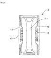
- a handle 10 has a so-called Y-shape (see Fig. 7 showing a plane cross-sectional view of the handle 10), and comprises a grip plate 11 integrally disposed in parallel between a pair of upper and lower fitting bent beams 12 in an upright posture.
- Embedded projecting pieces 17 are disposed at each fore-front of the fitting bent beam 12, and at the time of insert molding, are fitted by an undercut engagement to right and left portions of a wide, vertical projecting wall 105, which has been formed on a bottom of a recession 104 of the bottle 101, so that the handle 10 is fitted firmly to the bottle 101. Because a pair of fitting bent beams 12 is fitted and secured firmly to the bottle 101, the Y-shaped handle 10 can advantageously support the bottle 101 stably even when the bottle 101 is filled with liquid contents and has a heavy weight.
- This invention is aimed at material saving and cost reduction.
- a technical problem to be solved by the invention is to provide a light-weight Y-shaped handle without impairing injection moldability and the functions of the handle.
- the means of carrying out the invention according to claim 1 to solve the above-described technical problem is an injection molded, so-called Y-shaped handle used by being fitted and secured firmly to a rear portion of a body of a synthetic resin bottle by an insert molding method.
- the handle comprises a pair of fitting bent beams disposed in parallel in an upright posture and fitted in an undercut engagement to the rear portion of the body, a grip plate in a vertical and long rectangular shape disposed between the pair of the fitting bent beams, and a circular gate area disposed in a central area of the grip plate, wherein the thickness of the grip plate is reduced on both sides thereof in a certain height range to form thin plate portions, while leaving, as thick portions, a near-gate area including and surrounding the gate area in a concentric manner and vertical slip portions extending up- and down-ward from the near-gate area.
- weight saving can be achieved for the handle by forming thin plate portions on both sides of the grip plate while leaving the vertical slip portions intact.
- the vertical slip portions remain thick and serve as vertical ribs to make up for decreased rigidity caused by the thinned grip plate, i.e., the portion to be held with a hand.
- a molten resin is injected from a nozzle of an injection molding machine, and is flowed into the gate area through a mold gate in a position opposed to the gate area at the center of the grip plate. Then, the resin flows through the portions of the mold cavity corresponding to the resulting grip plate in two directions: upward and downward.
- Each resin flow soon diverges into right and left ways at both of upper and lower ends, and the separate resin flows go through the portions becoming a pair of fitting bent beams.
- the resin flow coming from above joins the flow coming from below together at a middle height of the portions of the resulting pair of fitting bent beams.
- the resin enters the cavity through the gate area, flows upward and downward, diverges right and left, and goes half around to form a pair of loops, thus requiring a long flow distance.
- some weight saving of the grip plate is achieved by reducing the thickness of the grip plate partially. In that case, it is ensured that the near-gate area, including and surrounding the gate area in a concentric manner, is kept from reducing the thickness. If this is done, then decreases in temperature and pressure can be controlled for the molten resin flowing into the gate area through the mold gate. Thus, the molten resin can be supplied smoothly in both the upward and downward directions.
- the vertical slip portions remain to be thick through to the upper and lower ends of the flat plate portion, i.e., in the directions of resin flows. Since the slip portions run along a vertical center line of the grip plate and extend upward and downward from the near-gate area, these portions help effectively control the decreases in temperature and pressure of the resin flowing through the portion corresponding to the resulting grip plate, and allow the resin to move smoothly toward the upper and lower ends of the grip plate portion once the resin has been supplied from the near-gate area upward and downward. On the whole, the remaining thick portions can make up for a decrease in resin flowability caused by the thin portions of the grip plate, and effectively secure injection moldability of the Y-shaped handle having a long flow distance.
- the diameter of the near-gate area, the width and height range of the vertical slip portions, and the extent to which the grip plate is thinned can be determined by taking into consideration the effect of weight saving and the injection moldability.
- this area is designed to be substantially concentric with the circular gate area.
- the means of carrying out the invention of claim 2 comprises that, in the invention of claim 1, the near-gate area has a diameter 1.3 times or more, and preferably 1.5 times or more, the diameter of the gate area.
- the decrease in resin temperature and pressure in the near-gate area can be effectively controlled by setting the diameter of the near-gate area at 1.3 times or more, and preferably 1.5 times or more, the diameter of the gate area.
- the means of carrying out the invention of claim 3 comprises that, in the invention of claim 1 or 2, the vertical slip portions has a lateral width 0.3 times or more, and preferably 0.5 times or more, the diameter of the gate area.
- the resin supplied from the gate area can be flowed smoothly toward the upper and lower ends of the resulting grip plate, by setting the lateral width of the vertical slip portions at 0.3 times or more, and preferably 0.5 times or more, the diameter of the gate area.
- the means of carrying out the invention of claim 4 comprises that in the invention of claim 1, 2, or 3, the handle is made of a PET resin.
- the handle made of a PET resin is highly rigid, the handle is relatively brittle as compared to, e.g., a handle made of a polypropylene resin. If the entire grip plate is made thin, there might be crack development when sudden force acts on the grip plate. Under the above construction of claim 4, the vertical slip portions remaining thick can withstand such force so that any crack can be prevented effectively from occurring.
- the near-gate area also performs the function of controlling the decreases in the temperature and pressure of molten resin flowing in through the gate area, and from the near-gate area, the supplied resin can be smoothly flowed through to the upper and lower ends of the resulting grip plate, by leaving the vertical slip portions to be thick along the direction of resin flow. On the whole, the portions remaining thick can make up for a decrease in resin flowability caused by the thin portions of the grip plate, and effectively secure injection moldability of the Y-shaped handle having a long flow distance.
- the decreases in resin temperature and pressure in the near-gate area can be effectively controlled by setting the diameter of the near-gate area at 1.3 times or more, and preferably 1.5 times or more, the diameter of the gate area.
- the resin supplied from the gate area can be flowed smoothly toward the upper and lower ends of the resulting grip plate, by setting the lateral width of the vertical slip portions at 0.3 times or more, and preferably 0.5 times or more, the diameter of the gate area.
- the vertical slip portions remaining thick can withstand the action of force so that any crack can be prevented effectively from occurring in the PET resin handle having a relatively brittle property.
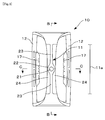
- Figs. 1-5 show the handle in an embodiment of this invention, in which Fig. 1 is a rear view; Fig. 2 , a front view; Fig. 3 , a vertical section taken from line B-B in Fig. 1 ; Fig. 4 , a plane cross-sectional view taken from line C-C shown in Fig. 1 ; and Figs. 5 , enlarged views of important parts of the grip plate of the handle, in which Fig. 5(a) is a rear view; Figs. 5(b) and 5(c) are plane cross-sectional views taken respectively from line E-E and line F-F shown in Fig. 5(a) .
- This handle 10 is an injection molded product made of a PET resin. It is set in a blow mold as an insert material, and is fitted and secured firmly to the rear of a PET resin bottle 101 at the time of a biaxial drawing and blow molding operation. (See Fig. 6 .)
- the handle 10 comprises a grip plate 11 in the form of a vertical plate, a pair of fitting bent beams 12 connected to upper and lower bent ends of the grip plate 11 and disposed in parallel at positions opposed to each other, and embedded projecting pieces 17 disposed at each forefront of the pair of fitting bent beams 12 and connected to a recession bottom 104 of the bottle 101 in an undercut engagement.
- a pair of the embedded projecting pieces 17 is disposed vertically on each fitting bent beam 12 in this embodiment (See Fig. 7 ).
- a plurality of lateral grooves 18 is also formed, taking into consideration the slidability of the PET resin which is drawn and molded at the time of insert molding.
- a near-gate area 22 is disposed to include and surround the gate area 21 in a concentric manner (See a circle drawn by a chain double-dashed line in Fig. 5(a) ). Furthermore, vertical slip portions 23 extend up- and down-ward from the near-gate area 22. The thickness of the grip plate is reduced on both right and left sides of the flat plate portion 11a to form thin plate portions 24, while leaving, as thick portions, the near-gate area 22 and the vertical slip portions23.
- the flat plate portion 11a of the handle 10 has the following dimensions:
- the above-described handle 10 could have been injection molded easily under normal conditions without any short shot.
- the handle 10 was used as an insert material to form a biaxially drawn, blow molded PET resin bottle having a nominal capacity of 1.8 liters.
- the bottle was filled with contents to check on whether or not this handle 10 is useful for the user to hold the bottle firmly with a hand. Owing to the vertical rib function fully performed by the vertical slip portions 23 which has remained thick, the handle 10 showed a good gripping property, and could bear the weight of the bottle filled with the contents.
- the synthetic resin handle of this invention has been described above with respect to a preferred embodiment, it should be noted that this invention is not limited to this embodiment.
- the resin to be used is not limited to the PET resin, but other resins, including polypropylene resins, can also be used.
- the embedded projecting pieces used to achieve an undercut engagement there are various shapes and structures that can be employed in this invention.
- the diameter D2 of the near-gate area and the lateral width W2 of the vertical slip portions can be determined arbitrarily in a comparison with the diameter D1 of the gate area and the lateral width W1 of the grip plate 11, while taking a target weight saving effect and injection moldability into consideration.
- shape of the near-gate area it is preferred to use, as a standard, a circular shape that is concentric with the circular gate area and to design a shape by deforming that shape appropriately.
- the synthetic resin handle of this invention is as described above.
- the weight saving for the handle can be achieved by reducing the thickness of the grip plate without impairing the injection moldability and the bottle gripping property.
- the handle of this invention is expected to have a wide range of applications as being used with biaxially drawn, blow molded bottles.
Landscapes
- Engineering & Computer Science (AREA)
- Mechanical Engineering (AREA)
- Details Of Rigid Or Semi-Rigid Containers (AREA)
- Moulds For Moulding Plastics Or The Like (AREA)
Abstract
Description
- This invention relates to a synthetic resin handle used by being fitted and secured firmly to a synthetic resin bottle by an insert molding method.
- Patent document 1 describes a synthetic resin bottle with a handle manufactured by biaxially drawing and blow molding a bottle made of a polyethylene terephthalate resin (hereinafter referred to as PET) while utilizing, as an insert material, a handle that has been preliminarily injection molded into a certain shape. (See
Figs. 6-8 .) - A
bottle 101 has arecession 103 sunken at the rear of abody 102. Ahandle 10 has a so-called Y-shape (seeFig. 7 showing a plane cross-sectional view of the handle 10), and comprises agrip plate 11 integrally disposed in parallel between a pair of upper and lowerfitting bent beams 12 in an upright posture. Embeddedprojecting pieces 17 are disposed at each fore-front of thefitting bent beam 12, and at the time of insert molding, are fitted by an undercut engagement to right and left portions of a wide,vertical projecting wall 105, which has been formed on a bottom of arecession 104 of thebottle 101, so that thehandle 10 is fitted firmly to thebottle 101. Because a pair offitting bent beams 12 is fitted and secured firmly to thebottle 101, the Y-shaped handle 10 can advantageously support thebottle 101 stably even when thebottle 101 is filled with liquid contents and has a heavy weight. - Patent document 1: Published patent application
JP2004-059136 - This invention is aimed at material saving and cost reduction. A technical problem to be solved by the invention is to provide a light-weight Y-shaped handle without impairing injection moldability and the functions of the handle.
- The means of carrying out the invention according to claim 1 to solve the above-described technical problem is an injection molded, so-called Y-shaped handle used by being fitted and secured firmly to a rear portion of a body of a synthetic resin bottle by an insert molding method. The handle comprises a pair of fitting bent beams disposed in parallel in an upright posture and fitted in an undercut engagement to the rear portion of the body, a grip plate in a vertical and long rectangular shape disposed between the pair of the fitting bent beams, and a circular gate area disposed in a central area of the grip plate, wherein the thickness of the grip plate is reduced on both sides thereof in a certain height range to form thin plate portions, while leaving, as thick portions, a near-gate area including and surrounding the gate area in a concentric manner and vertical slip portions extending up- and down-ward from the near-gate area.
- Under the above construction of claim 1, weight saving can be achieved for the handle by forming thin plate portions on both sides of the grip plate while leaving the vertical slip portions intact. The vertical slip portions remain thick and serve as vertical ribs to make up for decreased rigidity caused by the thinned grip plate, i.e., the portion to be held with a hand.
- In the case of Y-shaped handles of this type, a molten resin is injected from a nozzle of an injection molding machine, and is flowed into the gate area through a mold gate in a position opposed to the gate area at the center of the grip plate. Then, the resin flows through the portions of the mold cavity corresponding to the resulting grip plate in two directions: upward and downward. Each resin flow soon diverges into right and left ways at both of upper and lower ends, and the separate resin flows go through the portions becoming a pair of fitting bent beams. The resin flow coming from above joins the flow coming from below together at a middle height of the portions of the resulting pair of fitting bent beams. Thus, the resin enters the cavity through the gate area, flows upward and downward, diverges right and left, and goes half around to form a pair of loops, thus requiring a long flow distance.
- In order for the weight saving to be achieved, it would be necessary to give consideration to resin flowability if reduced thickness is given to an element of a molded product. Under the construction of the invention according to claim 1, some weight saving of the grip plate is achieved by reducing the thickness of the grip plate partially. In that case, it is ensured that the near-gate area, including and surrounding the gate area in a concentric manner, is kept from reducing the thickness. If this is done, then decreases in temperature and pressure can be controlled for the molten resin flowing into the gate area through the mold gate. Thus, the molten resin can be supplied smoothly in both the upward and downward directions.
- In addition, the vertical slip portions remain to be thick through to the upper and lower ends of the flat plate portion, i.e., in the directions of resin flows. Since the slip portions run along a vertical center line of the grip plate and extend upward and downward from the near-gate area, these portions help effectively control the decreases in temperature and pressure of the resin flowing through the portion corresponding to the resulting grip plate, and allow the resin to move smoothly toward the upper and lower ends of the grip plate portion once the resin has been supplied from the near-gate area upward and downward. On the whole, the remaining thick portions can make up for a decrease in resin flowability caused by the thin portions of the grip plate, and effectively secure injection moldability of the Y-shaped handle having a long flow distance.
- The diameter of the near-gate area, the width and height range of the vertical slip portions, and the extent to which the grip plate is thinned can be determined by taking into consideration the effect of weight saving and the injection moldability. Although there is no limitation to the shape of the near-gate area, it is preferred that in principle, this area is designed to be substantially concentric with the circular gate area.
- The means of carrying out the invention of claim 2 comprises that, in the invention of claim 1, the near-gate area has a diameter 1.3 times or more, and preferably 1.5 times or more, the diameter of the gate area.
- Under the construction of claim 2, the decrease in resin temperature and pressure in the near-gate area can be effectively controlled by setting the diameter of the near-gate area at 1.3 times or more, and preferably 1.5 times or more, the diameter of the gate area.
- The means of carrying out the invention of claim 3 comprises that, in the invention of claim 1 or 2, the vertical slip portions has a lateral width 0.3 times or more, and preferably 0.5 times or more, the diameter of the gate area.
- Under the above construction of claim 3, the resin supplied from the gate area can be flowed smoothly toward the upper and lower ends of the resulting grip plate, by setting the lateral width of the vertical slip portions at 0.3 times or more, and preferably 0.5 times or more, the diameter of the gate area.
- The means of carrying out the invention of claim 4 comprises that in the invention of claim 1, 2, or 3, the handle is made of a PET resin.
- Although the handle made of a PET resin is highly rigid, the handle is relatively brittle as compared to, e.g., a handle made of a polypropylene resin. If the entire grip plate is made thin, there might be crack development when sudden force acts on the grip plate. Under the above construction of claim 4, the vertical slip portions remaining thick can withstand such force so that any crack can be prevented effectively from occurring.
- This invention having above construction has the following effects:
- According to the invention of claim 1, the thick vertical slip portions perform the function of vertical ribs and can make up for decreased rigidity caused by the thinned grip plate to be held with a hand.
- The near-gate area also performs the function of controlling the decreases in the temperature and pressure of molten resin flowing in through the gate area, and from the near-gate area, the supplied resin can be smoothly flowed through to the upper and lower ends of the resulting grip plate, by leaving the vertical slip portions to be thick along the direction of resin flow. On the whole, the portions remaining thick can make up for a decrease in resin flowability caused by the thin portions of the grip plate, and effectively secure injection moldability of the Y-shaped handle having a long flow distance.
- According to the invention of claim 2, the decreases in resin temperature and pressure in the near-gate area can be effectively controlled by setting the diameter of the near-gate area at 1.3 times or more, and preferably 1.5 times or more, the diameter of the gate area.
- According to the invention of claim 3, the resin supplied from the gate area can be flowed smoothly toward the upper and lower ends of the resulting grip plate, by setting the lateral width of the vertical slip portions at 0.3 times or more, and preferably 0.5 times or more, the diameter of the gate area.
- According to the invention of claim 4, the vertical slip portions remaining thick can withstand the action of force so that any crack can be prevented effectively from occurring in the PET resin handle having a relatively brittle property.
-
-
Fig. 1 is a rear view showing the handle in one embodiment of this invention. -
Fig. 2 is a front view of the handle shown inFig. 1 . -
Fig. 3 is a vertical section of the handle taken from line B-B inFig. 1 . -
Fig. 4 is a plane cross-sectional view of the handle taken from line C-C shown inFig. 1 . -
Figs. 5 are enlarged views of important parts of the grip plate of the handle, in whichFig. 5(a) is a rear view;Figs. 5(b) and 5(c) are plane cross-sectional views taken respectively from line E-E and line F-F shown inFig. 5(a) . -
Fig. 6 is an entire side view of an example of the synthetic resin bottle with a handle. -
Fig. 7 is a plane cross-sectional view of the synthetic resin bottle with a handle taken from line A-A shown inFig. 6 . -
Fig. 8 is a front view of the handle shown inFig. 7 . -
- 10.
- Handle
- 11.
- Grip plate
- 11A.
- Flat plate portion
- 12.
- Fitting bent beam
- 17.
- Embedded projecting piece
- 18.
- Lateral groove
- 21.
- Gate area
- 22.
- Near-gate area
- 23.
- Vertical slip portion
- 24.
- Thin plate portion
- 101.
- Bottle
- 102.
- Body
- 103.
- Recession
- 104.
- Bottom of recession
- 105.
- Vertical projecting wall
- W1, W2.
- Lateral width
- D1, D2.
- Diameter
- t1, t2.
- Plate thickness
- This invention is further described with respect to a preferred embodiment, now referring to the drawings.
Figs. 1-5 show the handle in an embodiment of this invention, in whichFig. 1 is a rear view;Fig. 2 , a front view;Fig. 3 , a vertical section taken from line B-B inFig. 1 ;Fig. 4 , a plane cross-sectional view taken from line C-C shown inFig. 1 ; andFigs. 5 , enlarged views of important parts of the grip plate of the handle, in whichFig. 5(a) is a rear view;Figs. 5(b) and 5(c) are plane cross-sectional views taken respectively from line E-E and line F-F shown inFig. 5(a) . - This
handle 10 is an injection molded product made of a PET resin. It is set in a blow mold as an insert material, and is fitted and secured firmly to the rear of aPET resin bottle 101 at the time of a biaxial drawing and blow molding operation. (SeeFig. 6 .) - The
handle 10 comprises agrip plate 11 in the form of a vertical plate, a pair of fittingbent beams 12 connected to upper and lower bent ends of thegrip plate 11 and disposed in parallel at positions opposed to each other, and embedded projectingpieces 17 disposed at each forefront of the pair of fittingbent beams 12 and connected to arecession bottom 104 of thebottle 101 in an undercut engagement. As found fromFig. 3 , a pair of the embedded projectingpieces 17 is disposed vertically on each fittingbent beam 12 in this embodiment (SeeFig. 7 ). In addition, a plurality oflateral grooves 18 is also formed, taking into consideration the slidability of the PET resin which is drawn and molded at the time of insert molding. - There is a
circular gate area 21 in the central area at the rear of a rectangularflat plate portion 11a where thegrip plate 11 is disposed standing upright (SeeFigs. 1 and3 ). Anear-gate area 22 is disposed to include and surround thegate area 21 in a concentric manner (See a circle drawn by a chain double-dashed line inFig. 5(a) ). Furthermore,vertical slip portions 23 extend up- and down-ward from thenear-gate area 22. The thickness of the grip plate is reduced on both right and left sides of theflat plate portion 11a to formthin plate portions 24, while leaving, as thick portions, thenear-gate area 22 and the vertical slip portions23. - Plate thickness was reduced to obtain the
thin portions 24, and to form thehandle 10 having a weight of 12.5 g. This reduction in plate thickness resulted in the weight saving of 2.6 g. In this embodiment, theflat plate portion 11a of thehandle 10 has the following dimensions: - (1) The
flat plate portion 11a has a height of 58 mm and a lateral width W1 of 10 mm (except for the upper and lower ends where the width is somewhat expanded) - (2) The
vertical slip portions 23 and thenear-gate area 22 have a thickness t1 of 4 mm. - (3) The
thin plate portions 24 have an average thickness t2 of 2.25 mm. - (4) The
gate area 21 has a diameter D1 of 5 mm, and thenear-gate area 22 has a diameter D2 of 8 mm (D2/D1=1.6). - (5) The
vertical slip portions 23 have a lateral width W2 of 3 mm (W2/D1=0.6). If resin flowability is taken into consideration, it is preferred that the lateral width is changed gradually at the connections between thenear-gate area 22 and thevertical slip portions 22, as found in this embodiment. - The above-described
handle 10 could have been injection molded easily under normal conditions without any short shot. Thehandle 10 was used as an insert material to form a biaxially drawn, blow molded PET resin bottle having a nominal capacity of 1.8 liters. The bottle was filled with contents to check on whether or not thishandle 10 is useful for the user to hold the bottle firmly with a hand. Owing to the vertical rib function fully performed by thevertical slip portions 23 which has remained thick, thehandle 10 showed a good gripping property, and could bear the weight of the bottle filled with the contents. - Although the synthetic resin handle of this invention has been described above with respect to a preferred embodiment, it should be noted that this invention is not limited to this embodiment. For example, the resin to be used is not limited to the PET resin, but other resins, including polypropylene resins, can also be used. As regards the embedded projecting pieces used to achieve an undercut engagement, there are various shapes and structures that can be employed in this invention.
- The diameter D2 of the near-gate area and the lateral width W2 of the vertical slip portions can be determined arbitrarily in a comparison with the diameter D1 of the gate area and the lateral width W1 of the
grip plate 11, while taking a target weight saving effect and injection moldability into consideration. Although there is no limitation to the shape of the near-gate area, it is preferred to use, as a standard, a circular shape that is concentric with the circular gate area and to design a shape by deforming that shape appropriately. - The synthetic resin handle of this invention is as described above. The weight saving for the handle can be achieved by reducing the thickness of the grip plate without impairing the injection moldability and the bottle gripping property. The handle of this invention is expected to have a wide range of applications as being used with biaxially drawn, blow molded bottles.
Claims (4)
- An injection molded synthetic resin handle used by being fitted and secured firmly to a rear portion of a body of a synthetic resin bottle by an insert molding method, the handle comprising:a pair of fitting bent beams (12) disposed in parallel in an upright posture and fitted to a rear portion of the body by an undercut engagement,a grip plate (11) in a vertical and long rectangular shape disposed between the pair of the fitting bent beams (12), anda circular gate area (21) disposed at a center of the grip plate (11),wherein the thickness of the grip plate (11) is reduced on both sides thereof in a certain height range to form thin plate portions (24), while leaving, as thick portions, a near-gate area (22) including and surrounding the gate area (21) in a concentric manner and vertical slip portions (23) extending up- and downward from the near-gate area (22).
- The synthetic resin handle according to claim 1 wherein the near-gate area (22) has a diameter (D2) 1.3 times or more the diameter (D1) of the gate area (21).
- The synthetic resin handle according to claim 1 or 2 wherein the vertical slip portions (23) has a lateral width (W2) 0.3 times or more the diameter (D1) of the gate area (21).
- The synthetic resin handle according to claim 1, 2, or 3 wherein the handle is made of a polyethylene terephthalate resin.
Applications Claiming Priority (2)
| Application Number | Priority Date | Filing Date | Title |
|---|---|---|---|
| JP2006351297A JP4919190B2 (en) | 2006-12-27 | 2006-12-27 | Synthetic resin handle for housing |
| PCT/JP2007/073642 WO2008081681A1 (en) | 2006-12-27 | 2007-12-07 | Synthetic resin handle for bottle body |
Publications (3)
| Publication Number | Publication Date |
|---|---|
| EP2098459A1 true EP2098459A1 (en) | 2009-09-09 |
| EP2098459A4 EP2098459A4 (en) | 2011-03-23 |
| EP2098459B1 EP2098459B1 (en) | 2015-08-05 |
Family
ID=39588364
Family Applications (1)
| Application Number | Title | Priority Date | Filing Date |
|---|---|---|---|
| EP07850247.3A Not-in-force EP2098459B1 (en) | 2006-12-27 | 2007-12-07 | Synthetic resin handle for bottle body |
Country Status (8)
| Country | Link |
|---|---|
| US (1) | US8162163B2 (en) |
| EP (1) | EP2098459B1 (en) |
| JP (1) | JP4919190B2 (en) |
| KR (1) | KR101379107B1 (en) |
| CN (1) | CN101405193B (en) |
| AU (1) | AU2007340753B2 (en) |
| CA (1) | CA2674570C (en) |
| WO (1) | WO2008081681A1 (en) |
Families Citing this family (1)
| Publication number | Priority date | Publication date | Assignee | Title |
|---|---|---|---|---|
| JP5985798B2 (en) * | 2011-05-27 | 2016-09-06 | 株式会社吉野工業所 | Bottle with handle |
Family Cites Families (10)
| Publication number | Priority date | Publication date | Assignee | Title |
|---|---|---|---|---|
| US3923191A (en) * | 1974-09-11 | 1975-12-02 | Fluoroware Inc | Wafer basket and handle |
| JPH0232950A (en) * | 1988-07-12 | 1990-02-02 | Toyo Seikan Kaisha Ltd | Synthetic resin container with handle and its manufacture |
| JPH0628896B2 (en) * | 1990-06-04 | 1994-04-20 | 東洋製罐株式会社 | Method and apparatus for manufacturing synthetic resin container with handle |
| US5535901A (en) * | 1993-05-17 | 1996-07-16 | Yoshino Kogyosho Co., Ltd. | Synthetic resin bottle with handle and its production method |
| JPH0939971A (en) * | 1995-07-27 | 1997-02-10 | Mitsubishi Plastics Ind Ltd | Plastic bottle with handle |
| JPH0977074A (en) * | 1995-09-18 | 1997-03-25 | Toppan Printing Co Ltd | Handles for plastic bottles |
| JPH09150834A (en) * | 1995-11-30 | 1997-06-10 | Yoshino Kogyosho Co Ltd | Synthetic resin bottle with handle |
| US6049945A (en) * | 1998-12-17 | 2000-04-18 | Graham Packaging Company L.P. | Stackable ergonomic handle |
| JP3872396B2 (en) | 2002-07-31 | 2007-01-24 | 株式会社吉野工業所 | Synthetic resin housing with handle |
| CN100482446C (en) * | 2002-07-31 | 2009-04-29 | 株式会社吉野工业所 | Bottle made of synthetic resin with handle |
-
2006
- 2006-12-27 JP JP2006351297A patent/JP4919190B2/en active Active
-
2007
- 2007-12-07 US US12/448,245 patent/US8162163B2/en active Active
- 2007-12-07 CA CA2674570A patent/CA2674570C/en active Active
- 2007-12-07 AU AU2007340753A patent/AU2007340753B2/en not_active Ceased
- 2007-12-07 WO PCT/JP2007/073642 patent/WO2008081681A1/en not_active Ceased
- 2007-12-07 KR KR1020087023559A patent/KR101379107B1/en not_active Expired - Fee Related
- 2007-12-07 CN CN200780009469XA patent/CN101405193B/en not_active Expired - Fee Related
- 2007-12-07 EP EP07850247.3A patent/EP2098459B1/en not_active Not-in-force
Also Published As
| Publication number | Publication date |
|---|---|
| WO2008081681A1 (en) | 2008-07-10 |
| KR20090096658A (en) | 2009-09-14 |
| CN101405193A (en) | 2009-04-08 |
| AU2007340753A1 (en) | 2008-07-10 |
| US8162163B2 (en) | 2012-04-24 |
| US20100282708A1 (en) | 2010-11-11 |
| AU2007340753B2 (en) | 2013-01-31 |
| CN101405193B (en) | 2011-04-06 |
| CA2674570A1 (en) | 2008-07-10 |
| EP2098459A4 (en) | 2011-03-23 |
| EP2098459B1 (en) | 2015-08-05 |
| JP2008162603A (en) | 2008-07-17 |
| CA2674570C (en) | 2012-10-09 |
| JP4919190B2 (en) | 2012-04-18 |
| KR101379107B1 (en) | 2014-03-31 |
Similar Documents
| Publication | Publication Date | Title |
|---|---|---|
| CN109878849B (en) | Container and method for manufacturing the same | |
| US7823737B2 (en) | Plastic container with substantially flat panels | |
| CN1194883C (en) | Plastic container with rounded shoulder, model device and manufacturing method thereof | |
| EP2468649B1 (en) | Synthetic rectangular bottle | |
| EP1886925B1 (en) | Resin storage container | |
| US9981768B1 (en) | Container and method of manufacturing the same | |
| US20120298666A1 (en) | Stopper for packaging container | |
| US6997337B1 (en) | Molded plastic flask | |
| EP2848461B1 (en) | Seat cushion frame for vehicle | |
| AU2012346089B2 (en) | Container with grip panel and annular rib having variable width | |
| US20070023384A1 (en) | Container and blow mold assembly | |
| WO2004000662A1 (en) | Synthetic resin-made quadrangular container | |
| BR112015023774B1 (en) | MOLDING APPARATUS AND METHOD FOR FORMING AN ARTICLE | |
| WO2002087978A1 (en) | Blow molding bottle | |
| EP2792466A1 (en) | Parison and container blow-molding method using same | |
| CA2474281A1 (en) | Synthetic resin thin-walled bottle container | |
| KR100643647B1 (en) | Synthetic resin bottle with grip | |
| EP2098459B1 (en) | Synthetic resin handle for bottle body | |
| EP2143653B1 (en) | Bottle with handle made of synthetic resin | |
| AU743879B2 (en) | Biaxially oriented bottle having handle | |
| US12371238B2 (en) | Shelving components tree system and method | |
| JP2000309320A (en) | Thin blow bottle | |
| EP2987743B1 (en) | Container having a container body and a handle mounted thereto | |
| RU201030U1 (en) | JERRY-CAN | |
| JP3865291B2 (en) | Liquid hollow container that can dispense the remaining solution inside |
Legal Events
| Date | Code | Title | Description |
|---|---|---|---|
| PUAI | Public reference made under article 153(3) epc to a published international application that has entered the european phase |
Free format text: ORIGINAL CODE: 0009012 |
|
| 17P | Request for examination filed |
Effective date: 20090624 |
|
| AK | Designated contracting states |
Kind code of ref document: A1 Designated state(s): AT BE BG CH CY CZ DE DK EE ES FI FR GB GR HU IE IS IT LI LT LU LV MC MT NL PL PT RO SE SI SK TR |
|
| DAX | Request for extension of the european patent (deleted) | ||
| A4 | Supplementary search report drawn up and despatched |
Effective date: 20110223 |
|
| GRAP | Despatch of communication of intention to grant a patent |
Free format text: ORIGINAL CODE: EPIDOSNIGR1 |
|
| INTG | Intention to grant announced |
Effective date: 20150312 |
|
| GRAS | Grant fee paid |
Free format text: ORIGINAL CODE: EPIDOSNIGR3 |
|
| GRAA | (expected) grant |
Free format text: ORIGINAL CODE: 0009210 |
|
| AK | Designated contracting states |
Kind code of ref document: B1 Designated state(s): AT BE BG CH CY CZ DE DK EE ES FI FR GB GR HU IE IS IT LI LT LU LV MC MT NL PL PT RO SE SI SK TR |
|
| REG | Reference to a national code |
Ref country code: GB Ref legal event code: FG4D |
|
| REG | Reference to a national code |
Ref country code: CH Ref legal event code: EP |
|
| REG | Reference to a national code |
Ref country code: AT Ref legal event code: REF Ref document number: 740550 Country of ref document: AT Kind code of ref document: T Effective date: 20150815 |
|
| REG | Reference to a national code |
Ref country code: IE Ref legal event code: FG4D |
|
| REG | Reference to a national code |
Ref country code: DE Ref legal event code: R096 Ref document number: 602007042479 Country of ref document: DE |
|
| REG | Reference to a national code |
Ref country code: AT Ref legal event code: MK05 Ref document number: 740550 Country of ref document: AT Kind code of ref document: T Effective date: 20150805 |
|
| REG | Reference to a national code |
Ref country code: FR Ref legal event code: PLFP Year of fee payment: 9 |
|
| REG | Reference to a national code |
Ref country code: LT Ref legal event code: MG4D |
|
| REG | Reference to a national code |
Ref country code: NL Ref legal event code: MP Effective date: 20150805 |
|
| PG25 | Lapsed in a contracting state [announced via postgrant information from national office to epo] |
Ref country code: GR Free format text: LAPSE BECAUSE OF FAILURE TO SUBMIT A TRANSLATION OF THE DESCRIPTION OR TO PAY THE FEE WITHIN THE PRESCRIBED TIME-LIMIT Effective date: 20151106 Ref country code: LV Free format text: LAPSE BECAUSE OF FAILURE TO SUBMIT A TRANSLATION OF THE DESCRIPTION OR TO PAY THE FEE WITHIN THE PRESCRIBED TIME-LIMIT Effective date: 20150805 Ref country code: FI Free format text: LAPSE BECAUSE OF FAILURE TO SUBMIT A TRANSLATION OF THE DESCRIPTION OR TO PAY THE FEE WITHIN THE PRESCRIBED TIME-LIMIT Effective date: 20150805 Ref country code: LT Free format text: LAPSE BECAUSE OF FAILURE TO SUBMIT A TRANSLATION OF THE DESCRIPTION OR TO PAY THE FEE WITHIN THE PRESCRIBED TIME-LIMIT Effective date: 20150805 |
|
| PG25 | Lapsed in a contracting state [announced via postgrant information from national office to epo] |
Ref country code: IS Free format text: LAPSE BECAUSE OF FAILURE TO SUBMIT A TRANSLATION OF THE DESCRIPTION OR TO PAY THE FEE WITHIN THE PRESCRIBED TIME-LIMIT Effective date: 20151205 Ref country code: ES Free format text: LAPSE BECAUSE OF FAILURE TO SUBMIT A TRANSLATION OF THE DESCRIPTION OR TO PAY THE FEE WITHIN THE PRESCRIBED TIME-LIMIT Effective date: 20150805 Ref country code: AT Free format text: LAPSE BECAUSE OF FAILURE TO SUBMIT A TRANSLATION OF THE DESCRIPTION OR TO PAY THE FEE WITHIN THE PRESCRIBED TIME-LIMIT Effective date: 20150805 Ref country code: PT Free format text: LAPSE BECAUSE OF FAILURE TO SUBMIT A TRANSLATION OF THE DESCRIPTION OR TO PAY THE FEE WITHIN THE PRESCRIBED TIME-LIMIT Effective date: 20151207 Ref country code: SE Free format text: LAPSE BECAUSE OF FAILURE TO SUBMIT A TRANSLATION OF THE DESCRIPTION OR TO PAY THE FEE WITHIN THE PRESCRIBED TIME-LIMIT Effective date: 20150805 Ref country code: PL Free format text: LAPSE BECAUSE OF FAILURE TO SUBMIT A TRANSLATION OF THE DESCRIPTION OR TO PAY THE FEE WITHIN THE PRESCRIBED TIME-LIMIT Effective date: 20150805 |
|
| PG25 | Lapsed in a contracting state [announced via postgrant information from national office to epo] |
Ref country code: NL Free format text: LAPSE BECAUSE OF FAILURE TO SUBMIT A TRANSLATION OF THE DESCRIPTION OR TO PAY THE FEE WITHIN THE PRESCRIBED TIME-LIMIT Effective date: 20150805 |
|
| PG25 | Lapsed in a contracting state [announced via postgrant information from national office to epo] |
Ref country code: IT Free format text: LAPSE BECAUSE OF FAILURE TO SUBMIT A TRANSLATION OF THE DESCRIPTION OR TO PAY THE FEE WITHIN THE PRESCRIBED TIME-LIMIT Effective date: 20150805 Ref country code: EE Free format text: LAPSE BECAUSE OF FAILURE TO SUBMIT A TRANSLATION OF THE DESCRIPTION OR TO PAY THE FEE WITHIN THE PRESCRIBED TIME-LIMIT Effective date: 20150805 Ref country code: DK Free format text: LAPSE BECAUSE OF FAILURE TO SUBMIT A TRANSLATION OF THE DESCRIPTION OR TO PAY THE FEE WITHIN THE PRESCRIBED TIME-LIMIT Effective date: 20150805 Ref country code: CZ Free format text: LAPSE BECAUSE OF FAILURE TO SUBMIT A TRANSLATION OF THE DESCRIPTION OR TO PAY THE FEE WITHIN THE PRESCRIBED TIME-LIMIT Effective date: 20150805 Ref country code: SK Free format text: LAPSE BECAUSE OF FAILURE TO SUBMIT A TRANSLATION OF THE DESCRIPTION OR TO PAY THE FEE WITHIN THE PRESCRIBED TIME-LIMIT Effective date: 20150805 |
|
| REG | Reference to a national code |
Ref country code: DE Ref legal event code: R097 Ref document number: 602007042479 Country of ref document: DE |
|
| PG25 | Lapsed in a contracting state [announced via postgrant information from national office to epo] |
Ref country code: RO Free format text: LAPSE BECAUSE OF FAILURE TO SUBMIT A TRANSLATION OF THE DESCRIPTION OR TO PAY THE FEE WITHIN THE PRESCRIBED TIME-LIMIT Effective date: 20150805 Ref country code: BE Free format text: LAPSE BECAUSE OF NON-PAYMENT OF DUE FEES Effective date: 20151231 |
|
| PLBE | No opposition filed within time limit |
Free format text: ORIGINAL CODE: 0009261 |
|
| STAA | Information on the status of an ep patent application or granted ep patent |
Free format text: STATUS: NO OPPOSITION FILED WITHIN TIME LIMIT |
|
| 26N | No opposition filed |
Effective date: 20160509 |
|
| PG25 | Lapsed in a contracting state [announced via postgrant information from national office to epo] |
Ref country code: LU Free format text: LAPSE BECAUSE OF FAILURE TO SUBMIT A TRANSLATION OF THE DESCRIPTION OR TO PAY THE FEE WITHIN THE PRESCRIBED TIME-LIMIT Effective date: 20151207 Ref country code: MC Free format text: LAPSE BECAUSE OF FAILURE TO SUBMIT A TRANSLATION OF THE DESCRIPTION OR TO PAY THE FEE WITHIN THE PRESCRIBED TIME-LIMIT Effective date: 20150805 |
|
| REG | Reference to a national code |
Ref country code: CH Ref legal event code: PL |
|
| PG25 | Lapsed in a contracting state [announced via postgrant information from national office to epo] |
Ref country code: SI Free format text: LAPSE BECAUSE OF FAILURE TO SUBMIT A TRANSLATION OF THE DESCRIPTION OR TO PAY THE FEE WITHIN THE PRESCRIBED TIME-LIMIT Effective date: 20150805 |
|
| REG | Reference to a national code |
Ref country code: IE Ref legal event code: MM4A |
|
| PG25 | Lapsed in a contracting state [announced via postgrant information from national office to epo] |
Ref country code: IE Free format text: LAPSE BECAUSE OF NON-PAYMENT OF DUE FEES Effective date: 20151207 Ref country code: CH Free format text: LAPSE BECAUSE OF NON-PAYMENT OF DUE FEES Effective date: 20151231 Ref country code: LI Free format text: LAPSE BECAUSE OF NON-PAYMENT OF DUE FEES Effective date: 20151231 |
|
| REG | Reference to a national code |
Ref country code: FR Ref legal event code: PLFP Year of fee payment: 10 |
|
| PG25 | Lapsed in a contracting state [announced via postgrant information from national office to epo] |
Ref country code: BE Free format text: LAPSE BECAUSE OF FAILURE TO SUBMIT A TRANSLATION OF THE DESCRIPTION OR TO PAY THE FEE WITHIN THE PRESCRIBED TIME-LIMIT Effective date: 20150805 |
|
| PG25 | Lapsed in a contracting state [announced via postgrant information from national office to epo] |
Ref country code: HU Free format text: LAPSE BECAUSE OF FAILURE TO SUBMIT A TRANSLATION OF THE DESCRIPTION OR TO PAY THE FEE WITHIN THE PRESCRIBED TIME-LIMIT; INVALID AB INITIO Effective date: 20071207 Ref country code: BG Free format text: LAPSE BECAUSE OF FAILURE TO SUBMIT A TRANSLATION OF THE DESCRIPTION OR TO PAY THE FEE WITHIN THE PRESCRIBED TIME-LIMIT Effective date: 20150805 |
|
| PG25 | Lapsed in a contracting state [announced via postgrant information from national office to epo] |
Ref country code: CY Free format text: LAPSE BECAUSE OF FAILURE TO SUBMIT A TRANSLATION OF THE DESCRIPTION OR TO PAY THE FEE WITHIN THE PRESCRIBED TIME-LIMIT Effective date: 20150805 |
|
| PG25 | Lapsed in a contracting state [announced via postgrant information from national office to epo] |
Ref country code: TR Free format text: LAPSE BECAUSE OF FAILURE TO SUBMIT A TRANSLATION OF THE DESCRIPTION OR TO PAY THE FEE WITHIN THE PRESCRIBED TIME-LIMIT Effective date: 20150805 Ref country code: MT Free format text: LAPSE BECAUSE OF FAILURE TO SUBMIT A TRANSLATION OF THE DESCRIPTION OR TO PAY THE FEE WITHIN THE PRESCRIBED TIME-LIMIT Effective date: 20150805 |
|
| REG | Reference to a national code |
Ref country code: FR Ref legal event code: PLFP Year of fee payment: 11 |
|
| PGFP | Annual fee paid to national office [announced via postgrant information from national office to epo] |
Ref country code: FR Payment date: 20211109 Year of fee payment: 15 Ref country code: GB Payment date: 20211028 Year of fee payment: 15 Ref country code: DE Payment date: 20211102 Year of fee payment: 15 |
|
| REG | Reference to a national code |
Ref country code: DE Ref legal event code: R119 Ref document number: 602007042479 Country of ref document: DE |
|
| GBPC | Gb: european patent ceased through non-payment of renewal fee |
Effective date: 20221207 |
|
| PG25 | Lapsed in a contracting state [announced via postgrant information from national office to epo] |
Ref country code: GB Free format text: LAPSE BECAUSE OF NON-PAYMENT OF DUE FEES Effective date: 20221207 Ref country code: DE Free format text: LAPSE BECAUSE OF NON-PAYMENT OF DUE FEES Effective date: 20230701 |
|
| PG25 | Lapsed in a contracting state [announced via postgrant information from national office to epo] |
Ref country code: FR Free format text: LAPSE BECAUSE OF NON-PAYMENT OF DUE FEES Effective date: 20221231 |