EP2098436A1 - Power steering gear housing with balanced flow pressure port - Google Patents
Power steering gear housing with balanced flow pressure port Download PDFInfo
- Publication number
- EP2098436A1 EP2098436A1 EP20090154098 EP09154098A EP2098436A1 EP 2098436 A1 EP2098436 A1 EP 2098436A1 EP 20090154098 EP20090154098 EP 20090154098 EP 09154098 A EP09154098 A EP 09154098A EP 2098436 A1 EP2098436 A1 EP 2098436A1
- Authority
- EP
- European Patent Office
- Prior art keywords
- passageway
- orifices
- power steering
- fluid
- axis
- Prior art date
- Legal status (The legal status is an assumption and is not a legal conclusion. Google has not performed a legal analysis and makes no representation as to the accuracy of the status listed.)
- Granted
Links
- 239000012530 fluid Substances 0.000 claims abstract description 61
- 238000004519 manufacturing process Methods 0.000 description 2
- 230000001154 acute effect Effects 0.000 description 1
- 230000007423 decrease Effects 0.000 description 1
- 230000003247 decreasing effect Effects 0.000 description 1
- 238000012986 modification Methods 0.000 description 1
- 230000004048 modification Effects 0.000 description 1
Images

Classifications
-
- B—PERFORMING OPERATIONS; TRANSPORTING
- B62—LAND VEHICLES FOR TRAVELLING OTHERWISE THAN ON RAILS
- B62D—MOTOR VEHICLES; TRAILERS
- B62D5/00—Power-assisted or power-driven steering
- B62D5/06—Power-assisted or power-driven steering fluid, i.e. using a pressurised fluid for most or all the force required for steering a vehicle
- B62D5/08—Power-assisted or power-driven steering fluid, i.e. using a pressurised fluid for most or all the force required for steering a vehicle characterised by type of steering valve used
-
- B—PERFORMING OPERATIONS; TRANSPORTING
- B62—LAND VEHICLES FOR TRAVELLING OTHERWISE THAN ON RAILS
- B62D—MOTOR VEHICLES; TRAILERS
- B62D5/00—Power-assisted or power-driven steering
- B62D5/06—Power-assisted or power-driven steering fluid, i.e. using a pressurised fluid for most or all the force required for steering a vehicle
-
- B—PERFORMING OPERATIONS; TRANSPORTING
- B62—LAND VEHICLES FOR TRAVELLING OTHERWISE THAN ON RAILS
- B62D—MOTOR VEHICLES; TRAILERS
- B62D5/00—Power-assisted or power-driven steering
- B62D5/06—Power-assisted or power-driven steering fluid, i.e. using a pressurised fluid for most or all the force required for steering a vehicle
- B62D5/08—Power-assisted or power-driven steering fluid, i.e. using a pressurised fluid for most or all the force required for steering a vehicle characterised by type of steering valve used
- B62D5/083—Rotary valves
-
- Y—GENERAL TAGGING OF NEW TECHNOLOGICAL DEVELOPMENTS; GENERAL TAGGING OF CROSS-SECTIONAL TECHNOLOGIES SPANNING OVER SEVERAL SECTIONS OF THE IPC; TECHNICAL SUBJECTS COVERED BY FORMER USPC CROSS-REFERENCE ART COLLECTIONS [XRACs] AND DIGESTS
- Y10—TECHNICAL SUBJECTS COVERED BY FORMER USPC
- Y10T—TECHNICAL SUBJECTS COVERED BY FORMER US CLASSIFICATION
- Y10T137/00—Fluid handling
- Y10T137/8593—Systems
- Y10T137/86493—Multi-way valve unit
- Y10T137/86574—Supply and exhaust
- Y10T137/86638—Rotary valve
- Y10T137/86646—Plug type
- Y10T137/86654—For plural lines
Definitions
- the subject invention generally relates to a power steering system for a vehicle, and more specifically to a gear housing of the power steering system.
- vehicular power steering systems include a pump in fluid communication with a gear housing.
- the gear housing defines a valve bore and supports a steering valve within the valve bore.
- the gear housing further defines a pressure port.
- a fluid line is attached to the pressure port and interconnects the pump and the gear housing.
- a passageway interconnects the pressure port and valve bore in fluid communication, with the passageway defining an orifice into the valve bore.
- the pump pressurizes and circulates a power steering fluid to the gear housing, and more specifically, the pump circulates the power steering fluid through the fluid line to the pressure port, and through the passageway into the valve bore.
- a typical gear housing is shown in Prior Art Figure 1 , in which the gear housing defines a single passageway, having a single orifice, interconnecting the pressure port and the valve bore.
- the entire volume of the power steering fluid enters the valve bore through the orifice via the passageway.
- Design constraints of the typical gear housings limit the area of the orifice permitting entry of the power steering fluid into the valve bore.
- having the entire volume of the power steering fluid enter through the single orifice creates an unbalanced or uneven flow of the power steering fluid through the valve bore.
- the unbalance flow of the power steering fluid causes undesirable vibrations in the steering valve, which produces an undesirable "hissing" noise noticeable by the occupants of the vehicle.
- the subject invention provides a power steering system for a vehicle.
- the power steering system comprises a reservoir for storing a supply of a fluid.
- a pump is in fluid communication with the reservoir. The pump pressurizes and circulates the fluid.
- a gear housing defines a valve bore, a pressure port and a plurality of orifices into the valve bore.
- the pressure port is in fluid communication with the pump, and receives the pressurized fluid from the pump.
- the plurality of orifices is in fluid communication with the valve bore and the pressure port. The plurality of orifices direct the fluid into the valve bore at multiple locations about the valve bore.
- the subject invention directs the power steering fluid into the valve bore through a plurality of orifices.
- the flow area through which the fluid flows is increased, which decreases the velocity of the fluid through the orifices.
- the decreased velocity reduces vibration in the steering valve and thereby reduces the undesirable "hissing" noise.
- a power steering system is shown at 20 in Figure 2 .
- the power steering system 20 described herein is commonly referred to as a rack and pinion steering system 20.
- the subject invention may be incorporated into and used with other types of power steering systems 20.
- the power steering system 20 includes a pump 22, a steering gear 24 and a reservoir 26.
- the reservoir 26 stores a supply of a power steering fluid.
- the pump 22 is in fluid communication with the reservoir 26 and in fluid communication with the steering gear 24.
- the steering gear 24 is in fluid communication with the reservoir 26.
- the fluid circulates from the pump 22, through the steering gear 24, and back to the reservoir 26.
- the pump 22 pressurizes the power steering fluid and circulates the power steering fluid through the power steering system 20, i.e., from the reservoir 26 to the steering gear 24, and from the steering gear 24 back to the reservoir 26.
- the steering gear 24 includes a gear housing 28.
- the gear housing 28 defines a pressure port 30, a valve bore 32, a plurality of orifices 34, 36 and a plurality of passageways 38, 40.
- the pressure port 30 is in fluid communication with the pump 22.
- the pressure port 30 receives the pressurize fluid from the pump 22.
- a first fluid line 42 connects the pump 22 with the gear housing 28 of the steering gear 24, and is attached to the steering gear 24 at the pressure port 30.
- a second fluid line 43 connects the gear housing 28 with the reservoir 26.
- the valve bore 32 extends along a bore axis 44.
- a steering valve 46 is disposed within the valve bore 32.
- the steering valve 46 directs the power steering fluid to one of a first chamber and a second chamber of a power piston disposed within or adjacent to the gear housing 28 to assist in moving the rack as is known in the art.
- the plurality of orifices 34, 36 is in fluid communication with and open into the valve bore 32.
- the plurality of passageways 38, 40 interconnect the plurality of orifices 34, 36 and the pressure port 30. Accordingly, the plurality of orifices 34, 36 are also in fluid communication with the pressure port 30.
- the plurality of orifices 34, 36 direct the power steering fluid into the valve bore 32 at multiple locations about the valve bore 32.
- Each of the plurality of orifices 34, 36 is disposed angularly about the bore axis 44 relative to all other of the plurality of orifices 34, 36.
- the flow of the power steering fluid is balanced, thereby reducing vibration of the steering valve 46 at high flows of the power steering fluid.
- the reduced vibration of the steering valve 46 reduces or eliminates the undesirable "hissing" noise heard by the occupants of the vehicle.
- the gear housing 28 may define any number of orifices 34, 36 opening into the valve bore 32, and that the plurality of orifices 34, 36 may be disposed at any desirable location about the bore axis 44.
- the plurality of orifices 34, 36 may include four orifices 34, 36 equally spaced about the bore axis 44, i.e., spaced ninety degrees apart from each other.
- the plurality of orifices 34, 36 need not be spaced equidistant from each other, and may be randomly spaced about the bore axis 44.
- the gear housing 28 may include a valve housing 48.
- the valve housing 48 may define the valve bore 32, the pressure port 30, the plurality of orifices 34, 36 and the plurality of passageways 38, 40.
- the valve housing 48 may be integrally formed with the gear housing 28. Alternatively, the valve housing 48 may be a separate component rigidly connected to the gear housing 28.
- the plurality of passageways 38, 40 includes a first passageway 38 and a second passageway 40
- the plurality of orifices 34, 36 includes a first orifice 34 and a second orifice 36.
- the first orifice 34 is in fluid communication with the first passageway 38
- the second orifice 36 is in fluid communication with the second passageway 40.
- the pressure port 30 is an opening that extends into the gear housing 28. Accordingly, the pressure port 30 extends along a port axis 50. It should be appreciated that the port axis 50 may be disposed in any desirable orientation to accommodate differing design and space restraints. It should be further appreciated that the orientation of the port axis 50 is not related to the bore axis 44.
- the first embodiment of the gear housing 28 includes the pressure port 30, and thereby the port axis 50, extending into the gear housing 28 in a direction generally transverse to the valve bore 32.
- at least one of the plurality of passageways 38, 40 i.e., at least one of the first passageway 38 and the second passageway 40, is co-planar with the port axis 50.
- both the first passageway 38 and the second passageway 40 are coplanar with the port axis 50.
- the first passageway 38 extends along a first axis 52
- the second passageway 40 extends along a second axis 54.
- the first axis 52 intersects the second axis 54. Accordingly, the first passageway 38 and the second passageway 40 are angled relative to each other, and form an acute angle therebetween.
- the power steering fluid enters the gear housing 28 through the pressure port 30, flows through the first passageway 38 and the second passageway 40 to the first orifice 34 and the second orifice 36 respectively, and into the valve bore 32.
- the steering valve 46 directs the power steering fluid to one of the first chamber and the second chamber of the power piston as is well known.
- the pressure port 30 is machined into the gear housing 28 first. After which, the first passageway 38 and the second passageway 40 are machined into the gear housing 28 via the pressure port 30, and into the valve bore 32.
- the second embodiment of the gear housing 28 includes the port axis 50 being disposed in a generally parallel relationship relative to the valve bore 32. At least one of the first passageway 38 and the second passageway 40 are disposed along a plane intersecting the port axis 50. As shown, the plane is perpendicular to the port axis 50. However, it should be appreciated that the plane need only be substantially perpendicular to the port axis 50, i.e., the plane may be disposed at an approximate, but not quite, perpendicular angle relative to the port axis 50.
- first passageway 38 and the second passageway 40 are co-planar. Additionally, the first passageway 38 and the second passageway 40 are parallel. A first plug 56 and a second plug 58 are disposed at a distal end of the first passageway 38 and the second passageway 40 respectively.
- the pressure port 30 is machined into the gear housing 28. After which, the first passageway 38 and the second passageway 40 are machined into the gear housing 28, and at least partially intersect the pressure port 30. The first passageway 38 and the second passageway 40 are machined past the pressure port 30 and into the valve bore 32. The first plug 56 and the second plug 58 seal the first passageway 38 and the second passageway 40 respectively, so that the power steering fluid does not leak from the gear housing 28. Accordingly, it should be appreciated that the power steering fluid flows into the pressure port 30, through the first passageway 38 and the second passageway 40 to and through the first orifice 34 and the second orifice 36 respectively. The first plug 56 and the second plug 58 prevent the power steering fluid from flowing through the first passageway 38 and the second passageway 40 in a direction away from the first orifice 34 and the second orifice 36 respectively.
- gear housing 28 may also define a plurality of pressure ports 30, with one of the plurality of passageways 38, 40 interconnecting each of the plurality of pressure ports 30 with one of the plurality of orifices 34, 36.
Landscapes
- Engineering & Computer Science (AREA)
- Chemical & Material Sciences (AREA)
- Combustion & Propulsion (AREA)
- Transportation (AREA)
- Mechanical Engineering (AREA)
- Power Steering Mechanism (AREA)
Abstract
Description
- The subject invention generally relates to a power steering system for a vehicle, and more specifically to a gear housing of the power steering system.
- Generally, vehicular power steering systems include a pump in fluid communication with a gear housing. The gear housing defines a valve bore and supports a steering valve within the valve bore. The gear housing further defines a pressure port. A fluid line is attached to the pressure port and interconnects the pump and the gear housing. A passageway interconnects the pressure port and valve bore in fluid communication, with the passageway defining an orifice into the valve bore. The pump pressurizes and circulates a power steering fluid to the gear housing, and more specifically, the pump circulates the power steering fluid through the fluid line to the pressure port, and through the passageway into the valve bore.
- A typical gear housing is shown in Prior Art
Figure 1 , in which the gear housing defines a single passageway, having a single orifice, interconnecting the pressure port and the valve bore. The entire volume of the power steering fluid enters the valve bore through the orifice via the passageway. Design constraints of the typical gear housings limit the area of the orifice permitting entry of the power steering fluid into the valve bore. At high fluid velocities, having the entire volume of the power steering fluid enter through the single orifice creates an unbalanced or uneven flow of the power steering fluid through the valve bore. The unbalance flow of the power steering fluid causes undesirable vibrations in the steering valve, which produces an undesirable "hissing" noise noticeable by the occupants of the vehicle. - The subject invention provides a power steering system for a vehicle. The power steering system comprises a reservoir for storing a supply of a fluid. A pump is in fluid communication with the reservoir. The pump pressurizes and circulates the fluid. A gear housing defines a valve bore, a pressure port and a plurality of orifices into the valve bore. The pressure port is in fluid communication with the pump, and receives the pressurized fluid from the pump. The plurality of orifices is in fluid communication with the valve bore and the pressure port. The plurality of orifices direct the fluid into the valve bore at multiple locations about the valve bore.
- Accordingly, the subject invention directs the power steering fluid into the valve bore through a plurality of orifices. By increasing the number of orifices through which the fluid enters the valve bore, the flow area through which the fluid flows is increased, which decreases the velocity of the fluid through the orifices. The decreased velocity reduces vibration in the steering valve and thereby reduces the undesirable "hissing" noise.
- Other advantages of the present invention will be readily appreciated, as the same becomes better understood by reference to the following detailed description when considered in connection with the accompanying drawings.
-
Figure 1 is a cross-sectional view of a known gear housing. -
Figure 2 is a schematic view of a power steering system. -
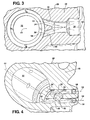
Figure 3 is a cross sectional view of a first embodiment of a gear housing of the power steering system. -
Figure 4 is a cross sectional view of a second embodiment of a gear housing of the power steering system. - Referring to the Figures, wherein like numerals indicate corresponding parts throughout the several views, a power steering system is shown at 20 in
Figure 2 . Thepower steering system 20 described herein is commonly referred to as a rack andpinion steering system 20. However, it should be appreciated that the subject invention may be incorporated into and used with other types ofpower steering systems 20. - Referring to
Figure 2 , thepower steering system 20 includes apump 22, asteering gear 24 and areservoir 26. Thereservoir 26 stores a supply of a power steering fluid. Thepump 22 is in fluid communication with thereservoir 26 and in fluid communication with thesteering gear 24. Thesteering gear 24 is in fluid communication with thereservoir 26. The fluid circulates from thepump 22, through thesteering gear 24, and back to thereservoir 26. Thepump 22 pressurizes the power steering fluid and circulates the power steering fluid through thepower steering system 20, i.e., from thereservoir 26 to thesteering gear 24, and from thesteering gear 24 back to thereservoir 26. - The
steering gear 24 includes agear housing 28. Thegear housing 28 defines apressure port 30, a valve bore 32, a plurality oforifices passageways pressure port 30 is in fluid communication with thepump 22. Thepressure port 30 receives the pressurize fluid from thepump 22. Afirst fluid line 42 connects thepump 22 with thegear housing 28 of thesteering gear 24, and is attached to thesteering gear 24 at thepressure port 30. Asecond fluid line 43 connects thegear housing 28 with thereservoir 26. - The
valve bore 32 extends along abore axis 44. Asteering valve 46 is disposed within thevalve bore 32. Thesteering valve 46 directs the power steering fluid to one of a first chamber and a second chamber of a power piston disposed within or adjacent to thegear housing 28 to assist in moving the rack as is known in the art. - The plurality of
orifices valve bore 32. The plurality ofpassageways orifices pressure port 30. Accordingly, the plurality oforifices pressure port 30. The plurality oforifices orifices bore axis 44 relative to all other of the plurality oforifices orifices steering valve 46 at high flows of the power steering fluid. The reduced vibration of thesteering valve 46 reduces or eliminates the undesirable "hissing" noise heard by the occupants of the vehicle. - It should be appreciated that the
gear housing 28 may define any number oforifices valve bore 32, and that the plurality oforifices bore axis 44. For example, the plurality oforifices orifices bore axis 44, i.e., spaced ninety degrees apart from each other. Alternatively, the plurality oforifices bore axis 44. - The
gear housing 28 may include avalve housing 48. Thevalve housing 48 may define thevalve bore 32, thepressure port 30, the plurality oforifices passageways valve housing 48 may be integrally formed with thegear housing 28. Alternatively, thevalve housing 48 may be a separate component rigidly connected to thegear housing 28. - As shown, the plurality of
passageways first passageway 38 and asecond passageway 40, and the plurality oforifices first orifice 34 and asecond orifice 36. Thefirst orifice 34 is in fluid communication with thefirst passageway 38, and thesecond orifice 36 is in fluid communication with thesecond passageway 40. - It should be appreciated that the
pressure port 30 is an opening that extends into thegear housing 28. Accordingly, thepressure port 30 extends along aport axis 50. It should be appreciated that theport axis 50 may be disposed in any desirable orientation to accommodate differing design and space restraints. It should be further appreciated that the orientation of theport axis 50 is not related to thebore axis 44. - Referring to
Figure 3 , a first embodiment of the gear housing is shown. The first embodiment of thegear housing 28 includes thepressure port 30, and thereby theport axis 50, extending into thegear housing 28 in a direction generally transverse to the valve bore 32. In the first embodiment of thegear housing 28, at least one of the plurality ofpassageways first passageway 38 and thesecond passageway 40, is co-planar with theport axis 50. As shown, both thefirst passageway 38 and thesecond passageway 40 are coplanar with theport axis 50. Thefirst passageway 38 extends along afirst axis 52, and thesecond passageway 40 extends along asecond axis 54. Thefirst axis 52 intersects thesecond axis 54. Accordingly, thefirst passageway 38 and thesecond passageway 40 are angled relative to each other, and form an acute angle therebetween. - It should be appreciated that the power steering fluid enters the
gear housing 28 through thepressure port 30, flows through thefirst passageway 38 and thesecond passageway 40 to thefirst orifice 34 and thesecond orifice 36 respectively, and into the valve bore 32. Once the power steering fluid enters the valve bore 32, the steeringvalve 46 directs the power steering fluid to one of the first chamber and the second chamber of the power piston as is well known. - In manufacture of the first embodiment of the
gear housing 28, thepressure port 30 is machined into thegear housing 28 first. After which, thefirst passageway 38 and thesecond passageway 40 are machined into thegear housing 28 via thepressure port 30, and into the valve bore 32. - Referring to
Figure 4 , a second embodiment of the gear housing is shown. The second embodiment of thegear housing 28 includes theport axis 50 being disposed in a generally parallel relationship relative to the valve bore 32. At least one of thefirst passageway 38 and thesecond passageway 40 are disposed along a plane intersecting theport axis 50. As shown, the plane is perpendicular to theport axis 50. However, it should be appreciated that the plane need only be substantially perpendicular to theport axis 50, i.e., the plane may be disposed at an approximate, but not quite, perpendicular angle relative to theport axis 50. - As shown in the second embodiment of the
gear housing 28, thefirst passageway 38 and thesecond passageway 40 are co-planar. Additionally, thefirst passageway 38 and thesecond passageway 40 are parallel. Afirst plug 56 and asecond plug 58 are disposed at a distal end of thefirst passageway 38 and thesecond passageway 40 respectively. - In manufacture, the
pressure port 30 is machined into thegear housing 28. After which, thefirst passageway 38 and thesecond passageway 40 are machined into thegear housing 28, and at least partially intersect thepressure port 30. Thefirst passageway 38 and thesecond passageway 40 are machined past thepressure port 30 and into the valve bore 32. Thefirst plug 56 and thesecond plug 58 seal thefirst passageway 38 and thesecond passageway 40 respectively, so that the power steering fluid does not leak from thegear housing 28. Accordingly, it should be appreciated that the power steering fluid flows into thepressure port 30, through thefirst passageway 38 and thesecond passageway 40 to and through thefirst orifice 34 and thesecond orifice 36 respectively. Thefirst plug 56 and thesecond plug 58 prevent the power steering fluid from flowing through thefirst passageway 38 and thesecond passageway 40 in a direction away from thefirst orifice 34 and thesecond orifice 36 respectively. - It should be appreciated that the
gear housing 28 may also define a plurality ofpressure ports 30, with one of the plurality ofpassageways pressure ports 30 with one of the plurality oforifices - The invention has been described in an illustrative manner, and it is to be understood that the terminology which has been used is intended to be in the nature of words of description rather than of limitation. As is now apparent to those skilled in the art, many modifications and variations of the present invention are possible in light of the above teachings. It is, therefore, to be understood that within the scope of the appended claims, wherein reference numerals are merely for convenience and are not to be in any way limiting, the invention may be practiced otherwise than as specifically described.
Claims (10)
- A power steering system (20) for a vehicle, said system (20) comprising:a reservoir (26) for storing a supply of a fluid;a pump (22) in fluid communication with said reservoir (26) for pressurizing and circulating the fluid;a gear housing (28) defining a pressure port (30) in fluid communication with said pump (22) for receiving the pressurized fluid from said pump (22);said gear housing (28) defining a valve bore (32) and a plurality of orifices (34, 36) in fluid communication with said valve bore (32) and said pressure port (30) for directing the fluid into said valve bore (32) at multiple locations about said valve bore (32).
- A system (20) as set forth in claim 1 wherein said valve bore (32) extends along a bore axis (44) and wherein each of said plurality of orifices (34, 36) is disposed angularly about said bore axis (44) relative to all other of said plurality of orifices (34, 36).
- A system (20) as set forth in any one of claims 1 and 2 further comprising a plurality of passageways (38, 40) interconnecting said plurality of orifices (34, 36) and said pressure port (30).
- A system (20) as set forth in claim 3 wherein said plurality of passageways (38, 40) includes a first passageway (38) and a second passageway (40) and said plurality of orifices (34, 36) includes a first orifice (34) in fluid communication with said first passageway (38) and a second orifice (36) in fluid communication with said second passageway (40).
- A system (20) as set forth in any one of claims 3 and 4 wherein said pressure port (30) extends along a port axis (50) and at least one of said plurality of passageways (38, 40) is co-planar with said port axis (50).
- A system (20) as set forth in claim 4 wherein said first passageway (38) extends along a first axis (52) and said second passageway (40) extends along a second axis (54) intersecting said first axis (52).
- A system (20) as set forth in claim 4 wherein said pressure port (30) extends along a port axis (50) and at least one of said first passageway (38) and said second passageway (40) is disposed along a plane intersecting said port axis (50).
- A system (20) as set forth in claim 7 wherein said plane is perpendicular to said port axis (50).
- A system (20) as set forth in any one of claims 7 and 8 wherein said first passageway (38) and said second passageway (40) are co-planar.
- A system (20) as set forth in any one of claims 7, 8 and 9 wherein said first passageway (38) and said second passageway (40) are parallel.
Applications Claiming Priority (2)
| Application Number | Priority Date | Filing Date | Title |
|---|---|---|---|
| US6820008P | 2008-03-04 | 2008-03-04 | |
| US12/371,707 US20090223581A1 (en) | 2008-03-04 | 2009-02-16 | Power steering gear housing with balanced flow pressure port |
Publications (2)
| Publication Number | Publication Date |
|---|---|
| EP2098436A1 true EP2098436A1 (en) | 2009-09-09 |
| EP2098436B1 EP2098436B1 (en) | 2011-08-03 |
Family
ID=40673699
Family Applications (1)
| Application Number | Title | Priority Date | Filing Date |
|---|---|---|---|
| EP20090154098 Expired - Fee Related EP2098436B1 (en) | 2008-03-04 | 2009-03-02 | Power steering gear housing with balanced flow pressure port |
Country Status (2)
| Country | Link |
|---|---|
| US (1) | US20090223581A1 (en) |
| EP (1) | EP2098436B1 (en) |
Citations (2)
| Publication number | Priority date | Publication date | Assignee | Title |
|---|---|---|---|---|
| US4258752A (en) * | 1978-09-30 | 1981-03-31 | Zahnradfabrik Friedrichshafen, Ag. | Control valve with two rotary valve elements supported in a housing and acted upon axially by pressure |
| US4651622A (en) | 1983-06-10 | 1987-03-24 | Mitsubishi Jidosha Kogyo Kabushiki Kaisha | Power steering system |
Family Cites Families (14)
| Publication number | Priority date | Publication date | Assignee | Title |
|---|---|---|---|---|
| GB1465445A (en) * | 1974-09-13 | 1977-02-23 | Ford Motor Co | Rack and pinion power steering gear |
| US4217812A (en) * | 1978-09-25 | 1980-08-19 | General Motors Corporation | Integral power steering gear with valve reaction device |
| US4232585A (en) * | 1978-10-16 | 1980-11-11 | General Motors Corporation | Power steering gear with flow check valve |
| GB2109756B (en) * | 1981-11-18 | 1985-02-06 | Cam Gears Ltd | Power assisted steering gear |
| US4828068A (en) * | 1984-02-02 | 1989-05-09 | General Motors Corporation | Hydraulically power assisted steering gear with pressure relief stop |
| DE3661183D1 (en) * | 1985-04-06 | 1988-12-22 | Zahnradfabrik Friedrichshafen Aktiengesellschaft | |
| US4673051A (en) * | 1986-03-10 | 1987-06-16 | General Motors Corporation | Power steering gear with two-way check valve |
| JP2525400B2 (en) * | 1987-03-26 | 1996-08-21 | 豊田工機株式会社 | Servo valve device for power steering device |
| US4809806A (en) * | 1988-05-06 | 1989-03-07 | General Motors Corporation | Steering gear with hybrid housing |
| JP2855446B2 (en) * | 1989-05-22 | 1999-02-10 | カヤバ工業株式会社 | Power steering device |
| US5249503A (en) * | 1990-01-05 | 1993-10-05 | William J. Weinstock | Variable ratio reaction valve |
| JPH0872733A (en) * | 1994-09-08 | 1996-03-19 | Kayaba Ind Co Ltd | Power steering device |
| JP3463495B2 (en) * | 1996-11-07 | 2003-11-05 | 豊田工機株式会社 | Power steering device |
| US6945352B2 (en) * | 2003-05-29 | 2005-09-20 | Techo Corporation | Force-based power steering system |
-
2009
- 2009-02-16 US US12/371,707 patent/US20090223581A1/en not_active Abandoned
- 2009-03-02 EP EP20090154098 patent/EP2098436B1/en not_active Expired - Fee Related
Patent Citations (2)
| Publication number | Priority date | Publication date | Assignee | Title |
|---|---|---|---|---|
| US4258752A (en) * | 1978-09-30 | 1981-03-31 | Zahnradfabrik Friedrichshafen, Ag. | Control valve with two rotary valve elements supported in a housing and acted upon axially by pressure |
| US4651622A (en) | 1983-06-10 | 1987-03-24 | Mitsubishi Jidosha Kogyo Kabushiki Kaisha | Power steering system |
Also Published As
| Publication number | Publication date |
|---|---|
| EP2098436B1 (en) | 2011-08-03 |
| US20090223581A1 (en) | 2009-09-10 |
Similar Documents
| Publication | Publication Date | Title |
|---|---|---|
| EP3199838B1 (en) | Fluid pump unit | |
| KR102110748B1 (en) | Hydraulic block for a hydraulic unit | |
| CN101769188B (en) | oil sump | |
| EP0207602A1 (en) | Fuel rail assembly | |
| US5975652A (en) | Electrohydraulic unit | |
| US6846050B2 (en) | Hydraulic unit for an anti-lock vehicle brake system | |
| US20040140009A1 (en) | Saddle tank fuel delivery system | |
| US6688707B1 (en) | Hydraulic aggregate | |
| US20030150603A1 (en) | Heat exchanger for a motor vehicle | |
| EP2016275B1 (en) | Fuel pump with inner channel priming | |
| US20100111718A1 (en) | Hydraulic System For A Transmission With Pump Inlet Diffuser | |
| KR20120046184A (en) | Pump housing of a motor vehicle hydraulic unit with at least one main cylinder connection opening | |
| KR100629659B1 (en) | Hydraulic appliance assembly | |
| US20230089947A1 (en) | Control device | |
| CN100377938C (en) | Nozzles and washing equipment for automotive glass washing equipment | |
| EP2098436B1 (en) | Power steering gear housing with balanced flow pressure port | |
| JP5028759B2 (en) | Fluid reservoir | |
| US7441843B2 (en) | Hydraulic unit | |
| US20200316621A1 (en) | Fuel distribution pipe | |
| WO2003058074A1 (en) | Unitary multi-flow connection | |
| US8740184B2 (en) | Magnet valve and driver assistance system | |
| CN104981604B (en) | Structural elements with high-pressure holes communicating with each other | |
| US6877961B2 (en) | Vane pump with a bypass valve and passage arrangement for equalizing excess fluid flow through dual suction passages | |
| US12480587B2 (en) | Hydraulic control unit valve porting, routing, checkball, and orifice integration with additive manufacturing | |
| WO2025011774A1 (en) | Pump housing |
Legal Events
| Date | Code | Title | Description |
|---|---|---|---|
| PUAI | Public reference made under article 153(3) epc to a published international application that has entered the european phase |
Free format text: ORIGINAL CODE: 0009012 |
|
| AK | Designated contracting states |
Kind code of ref document: A1 Designated state(s): AT BE BG CH CY CZ DE DK EE ES FI FR GB GR HR HU IE IS IT LI LT LU LV MC MK MT NL NO PL PT RO SE SI SK TR |
|
| AX | Request for extension of the european patent |
Extension state: AL BA RS |
|
| 17P | Request for examination filed |
Effective date: 20091202 |
|
| 17Q | First examination report despatched |
Effective date: 20100105 |
|
| AKX | Designation fees paid |
Designated state(s): DE FR GB |
|
| GRAP | Despatch of communication of intention to grant a patent |
Free format text: ORIGINAL CODE: EPIDOSNIGR1 |
|
| RAP1 | Party data changed (applicant data changed or rights of an application transferred) |
Owner name: GM GLOBAL TECHNOLOGY OPERATIONS, INC. |
|
| GRAS | Grant fee paid |
Free format text: ORIGINAL CODE: EPIDOSNIGR3 |
|
| GRAA | (expected) grant |
Free format text: ORIGINAL CODE: 0009210 |
|
| AK | Designated contracting states |
Kind code of ref document: B1 Designated state(s): DE FR GB |
|
| REG | Reference to a national code |
Ref country code: GB Ref legal event code: FG4D |
|
| REG | Reference to a national code |
Ref country code: DE Ref legal event code: R096 Ref document number: 602009001936 Country of ref document: DE Effective date: 20110929 |
|
| PGFP | Annual fee paid to national office [announced via postgrant information from national office to epo] |
Ref country code: FR Payment date: 20120406 Year of fee payment: 4 |
|
| PLBE | No opposition filed within time limit |
Free format text: ORIGINAL CODE: 0009261 |
|
| STAA | Information on the status of an ep patent application or granted ep patent |
Free format text: STATUS: NO OPPOSITION FILED WITHIN TIME LIMIT |
|
| 26N | No opposition filed |
Effective date: 20120504 |
|
| PGFP | Annual fee paid to national office [announced via postgrant information from national office to epo] |
Ref country code: DE Payment date: 20120328 Year of fee payment: 4 |
|
| REG | Reference to a national code |
Ref country code: DE Ref legal event code: R097 Ref document number: 602009001936 Country of ref document: DE Effective date: 20120504 |
|
| GBPC | Gb: european patent ceased through non-payment of renewal fee |
Effective date: 20130302 |
|
| REG | Reference to a national code |
Ref country code: FR Ref legal event code: ST Effective date: 20131129 |
|
| REG | Reference to a national code |
Ref country code: DE Ref legal event code: R119 Ref document number: 602009001936 Country of ref document: DE Effective date: 20131001 |
|
| PG25 | Lapsed in a contracting state [announced via postgrant information from national office to epo] |
Ref country code: DE Free format text: LAPSE BECAUSE OF NON-PAYMENT OF DUE FEES Effective date: 20131001 Ref country code: FR Free format text: LAPSE BECAUSE OF NON-PAYMENT OF DUE FEES Effective date: 20130402 Ref country code: GB Free format text: LAPSE BECAUSE OF NON-PAYMENT OF DUE FEES Effective date: 20130302 |