EP2098409A1 - Load carrier arrangement - Google Patents
Load carrier arrangement Download PDFInfo
- Publication number
- EP2098409A1 EP2098409A1 EP08102379A EP08102379A EP2098409A1 EP 2098409 A1 EP2098409 A1 EP 2098409A1 EP 08102379 A EP08102379 A EP 08102379A EP 08102379 A EP08102379 A EP 08102379A EP 2098409 A1 EP2098409 A1 EP 2098409A1
- Authority
- EP
- European Patent Office
- Prior art keywords
- load carrier
- slide
- roller mechanism
- load
- arrangement according
- Prior art date
- Legal status (The legal status is an assumption and is not a legal conclusion. Google has not performed a legal analysis and makes no representation as to the accuracy of the status listed.)
- Granted
Links
- 230000007246 mechanism Effects 0.000 claims abstract description 67
- 239000000969 carrier Substances 0.000 claims abstract description 17
- 239000002783 friction material Substances 0.000 claims description 2
- 229910000831 Steel Inorganic materials 0.000 description 3
- 239000010959 steel Substances 0.000 description 3
- 239000011248 coating agent Substances 0.000 description 2
- 238000000576 coating method Methods 0.000 description 2
- 239000004677 Nylon Substances 0.000 description 1
- 239000000956 alloy Substances 0.000 description 1
- 229910045601 alloy Inorganic materials 0.000 description 1
- 239000004411 aluminium Substances 0.000 description 1
- 229910052782 aluminium Inorganic materials 0.000 description 1
- XAGFODPZIPBFFR-UHFFFAOYSA-N aluminium Chemical compound [Al] XAGFODPZIPBFFR-UHFFFAOYSA-N 0.000 description 1
- 238000010276 construction Methods 0.000 description 1
- 230000005484 gravity Effects 0.000 description 1
- 239000000463 material Substances 0.000 description 1
- 229910052751 metal Inorganic materials 0.000 description 1
- 239000002184 metal Substances 0.000 description 1
- 150000002739 metals Chemical class 0.000 description 1
- 229920001778 nylon Polymers 0.000 description 1
- 239000004810 polytetrafluoroethylene Substances 0.000 description 1
- 229920001343 polytetrafluoroethylene Polymers 0.000 description 1
- 238000003466 welding Methods 0.000 description 1
Images


Classifications
-
- B—PERFORMING OPERATIONS; TRANSPORTING
- B60—VEHICLES IN GENERAL
- B60P—VEHICLES ADAPTED FOR LOAD TRANSPORTATION OR TO TRANSPORT, TO CARRY, OR TO COMPRISE SPECIAL LOADS OR OBJECTS
- B60P1/00—Vehicles predominantly for transporting loads and modified to facilitate loading, consolidating the load, or unloading
- B60P1/02—Vehicles predominantly for transporting loads and modified to facilitate loading, consolidating the load, or unloading with parallel up-and-down movement of load supporting or containing element
Definitions
- the present invention relates to a load carrier arrangement, and then particularly to a roller mechanism for raisable and lowerable load carriers in a loading compartment.
- Such arrangements are used primarily in the loading compartments of trucks, where the carriers support loads and can be raised and lowered to enable goods to be supported at several levels in the loading compartment.
- the load carrier according to the invention is especially arranged to be able to be handled by means of fork trucks or similar motor drive mechanical handling means.
- load carriers include at least one transverse load beam which carries at each end a slide or roller mechanism that co-acts with a corresponding vertical rail so as to enable the load carrier as a whole, to be moved up and down the vertical rail, with part of the slide mechanism or the rollers of the roller mechanism being movable within the vertical rail.
- Disposed at distances along the vertical carrier rail are preferably openings in which a locking pin projecting out from the slide or roller mechanism can engage and therewith lock the slide or roller mechanism and thereby the load carrier in a desired vertical position along the vertical carrier rail.
- the load carrier can comprise co-acting transverse load beams, or a floor mounted on the top of two co-acting load beams.
- a load carrier arrangement of the above type is previously known from, amongst others, the inventor's previous European patent applications EP-0 953 478 or EP-1 226 048 .
- a problem encountered with the above type of load carriers is that when the load carriers are raised or lowered, usually by the means of a fork truck, the force applied on the load carrier is not equally balanced. Due to the substantial transverse length of the load carrier, usually about 2.5 m, there is a risk that one end of the load carrier is moved faster that the other, resulting in a skewing of the load carrier and consequently also of the slide or roller mechanisms connected to the ends of the load carrier. Thereby the possibility to move the slide or roller mechanisms upwards or downwards in the vertical rails can be affected so far that the slide or roller mechanisms get jammed in the vertical rails, thereby preventing further movement of the load carrier.
- the articulated connection is preferably made so that the slide or roller mechanism can be pivoted in relation to the load carrier, as well as being somewhat displaceable in the transverse direction of the loading compartment in relation to the load carrier, i.e. in the longitudinal direction of a load beam.
- Fig. 1 shows a perspective view of a preferred embodiment of the roller mechanism
- Fig. 2 shows a side view of the roller mechanism shown in Fig. 1
- Fig. 3 shows a schematic front view of a load carrier with the preferred embodiment of roller mechanisms mounted at each end of the load carrier, not in scale
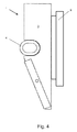
- Fig. 4 shows a view similar to that of Fig. 2 but showing a slide mechanism instead of a roller mechanism.
- Fig. 1 a preferred embodiment of a roller mechanism 1 as being a part of a load carrier arrangement according to the invention.
- the roller mechanism 1 comprises a main body 2, mainly made up of a piece of sheet steel bent to a U-profile.
- a recess is formed, into which a tube 4 is inserted, connecting the two opposing legs 3.
- the tube 4 is also of steel, and can be connected and secured in the recesses in the side walls 3 by means of welding.
- the roller mechanism 1 is connected to both ends of a load carrier 5, see Fig. 3 .
- the load carrier 5 and the roller mechanisms 1 are connected by means of a bolt and nut arrangement 6, of which the bolt passes through the tube 4 in the roller mechanism 1.
- the nut in the bolt and nut arrangement 6 is preferably a locking nut, so that connection between roller mechanism 1 and load carrier 5 can be secured without the necessity of tightening the parts immovably to each other.
- the load carrier 5 can quite simply be provided with a transverse hole through the carrier to let the bolt of the bolt and nut arrangement 6 pass there through.
- the roller mechanism 1 on its main body wall 7, connecting the two side walls 3, is provided with a number of guide wheels 8, arranged in a vertical row.
- the roller mechanism 1 is guided upwards and downwards along a guide rail (not shown) in the side walls of the loading compartment.
- the guide wheels 8 are located within the guide rail, with the shafts of the guide wheels extending through a vertical slot or opening in the guide rail, and consequently with the main body 2 of the roller mechanism located outside the guide rail.
- Each roller mechanism 1 should have at least two guide wheels 8 to obtaining a proper guiding in the guide rail, and as shown in the preferred embodiment in the drawings the preferred number of guide wheels 8 is three.
- the tube 4 inserted into the side walls 3 of the roller mechanism, and through which the connecting bolt of the bolt and nut arrangement 6 extends, is flattened so that it has an oval form and is longer in the direction crosswise to the longitudinal direction of the roller mechanism 1.
- the tube 4 has this oval form, it is possible for the bolt to move a short distance in the crosswise direction of the roller mechanism, and thereby it is possible for the roller mechanism to move to and from the end of the load carrier to which it is connected, and in this way adapt any distance variations depending to any skewing of the load carrier, or due to that the guide rails at the opposing sides of load carrier or loading compartment are not exactly parallel.
- the internal height of the oval tube essentially corresponds to the diameter of the bolt used, so that there is no substantial play in the vertical direction.
- the location of the tube 4, and of the bolt and nut arrangement 6, in the roller mechanism 1 is preferably above both the geometrical centre and the centre of gravity of the roller mechanism 1. By this location of the tube and bolt and nut arrangement the risk for jamming in the guide rail is reduced.
- the location of the tube 4 and bolt and nut arrangement 6 in horizontal direction rather close to the guide wheels 8 is advantageous as it creates only a very small lever for any forces applied from the load carried by the load carrier.
- the load carrier can as stated earlier comprise co-acting transverse load beams or a floor mounted on top of two coating load beams. In such cases it is the simplest to connect the roller mechanism 1 to the ends of the load beams. However, the load carrier may also be mad as a self-containing floor structure, and in such cases it would be necessary to have some form of connection points on the floor structure, for the connection to the roller mechanisms.
- oval tube 4 is inserted into the side walls 3 of the roller mechanism, for connection by means of the bolt and nut arrangement 6 to the load carrier. It is though also possible to have the oval tube inserted or connected to the load carrier 5, for connection to a roller mechanism thus pivotally connected to the load carrier by means of a bolt and nut arrangement passing through holes in the side walls 3 of the roller mechanism 1 as well as through the oval tube. However, such a solution would probably require additional strength measures for the roller mechanism.
- the mechanism can be a slide mechanism of essentially the same construction apart from the guide wheels that are replaced by a sliding part 9, such as a slide shoe, protruding into a longitudinal slot of a co-acting vertical rail, that can guide the mechanism along the vertical rail.
- a sliding part 9 such as a slide shoe
- Such a slide mechanism would have its sliding part 9, protruding into the vertical rail, being made of a low friction material, such as e.g. nylon or PTFE.
- roller mechanism in other materials such as aluminium or other metals or alloys.
- the load carrier arrangement according to the present application can favourably be combined with the load carrier arrangements defined in the inventor's previous European patent applications defined above.
- the load carrier arrangement according to the invention can consequently be constructed so that it can be completely raised to the top of the vertical rails and easily locked there so that it would be possible to drive with load carrying fork trucks under such raised load carriers, when loading or unloading the loading compartment.
Landscapes
- Engineering & Computer Science (AREA)
- Transportation (AREA)
- Mechanical Engineering (AREA)
- Handcart (AREA)
- Liquid Developers In Electrophotography (AREA)
- Led Device Packages (AREA)
- Fats And Perfumes (AREA)
- Forklifts And Lifting Vehicles (AREA)
Abstract
Description
- The present invention relates to a load carrier arrangement, and then particularly to a roller mechanism for raisable and lowerable load carriers in a loading compartment. Such arrangements are used primarily in the loading compartments of trucks, where the carriers support loads and can be raised and lowered to enable goods to be supported at several levels in the loading compartment. The load carrier according to the invention is especially arranged to be able to be handled by means of fork trucks or similar motor drive mechanical handling means.
- It is known to include in such arrangements vertical rails at both longitudinal edges of the loading compartment to enable the load carriers to be raised and lowered, said rails being disposed in pairs with each rail centrally opposite the other. These load carriers include at least one transverse load beam which carries at each end a slide or roller mechanism that co-acts with a corresponding vertical rail so as to enable the load carrier as a whole, to be moved up and down the vertical rail, with part of the slide mechanism or the rollers of the roller mechanism being movable within the vertical rail. Disposed at distances along the vertical carrier rail are preferably openings in which a locking pin projecting out from the slide or roller mechanism can engage and therewith lock the slide or roller mechanism and thereby the load carrier in a desired vertical position along the vertical carrier rail. The load carrier can comprise co-acting transverse load beams, or a floor mounted on the top of two co-acting load beams.
- A load carrier arrangement of the above type is previously known from, amongst others, the inventor's previous European patent applications
EP-0 953 478 orEP-1 226 048 . - A problem encountered with the above type of load carriers is that when the load carriers are raised or lowered, usually by the means of a fork truck, the force applied on the load carrier is not equally balanced. Due to the substantial transverse length of the load carrier, usually about 2.5 m, there is a risk that one end of the load carrier is moved faster that the other, resulting in a skewing of the load carrier and consequently also of the slide or roller mechanisms connected to the ends of the load carrier. Thereby the possibility to move the slide or roller mechanisms upwards or downwards in the vertical rails can be affected so far that the slide or roller mechanisms get jammed in the vertical rails, thereby preventing further movement of the load carrier.
- It is therefore an object of the present invention to provide a novel load carrier arrangement by means of which the above problem with the jamming of the slide or roller mechanism can be avoided.
- This object of the invention is obtained by means of a load carrier arrangement of the above type, wherein according to the invention the slide or roller mechanism is connected to the load carrier by means of an articulated connection.
- The articulated connection is preferably made so that the slide or roller mechanism can be pivoted in relation to the load carrier, as well as being somewhat displaceable in the transverse direction of the loading compartment in relation to the load carrier, i.e. in the longitudinal direction of a load beam.
- The invention will now be described in more detail with reference to the enclosed drawings showing a preferred but not limiting embodiment of a roller mechanism for the load carrier according to the invention. In the drawings
Fig. 1 shows a perspective view of a preferred embodiment of the roller mechanism,Fig. 2 shows a side view of the roller mechanism shown inFig. 1 ,Fig. 3 shows a schematic front view of a load carrier with the preferred embodiment of roller mechanisms mounted at each end of the load carrier, not in scale, andFig. 4 shows a view similar to that ofFig. 2 but showing a slide mechanism instead of a roller mechanism. - In
Fig. 1 is shown a preferred embodiment of aroller mechanism 1 as being a part of a load carrier arrangement according to the invention. Theroller mechanism 1 comprises amain body 2, mainly made up of a piece of sheet steel bent to a U-profile. In the edges of theside walls 3, or opposing legs, of the U-profiled roller mechanism body 2 a recess is formed, into which atube 4 is inserted, connecting the twoopposing legs 3. Thetube 4 is also of steel, and can be connected and secured in the recesses in theside walls 3 by means of welding. - The
roller mechanism 1 is connected to both ends of aload carrier 5, seeFig. 3 . According to the preferred embodiment of theroller mechanism 1 shown inFig. 1 theload carrier 5 and theroller mechanisms 1 are connected by means of a bolt andnut arrangement 6, of which the bolt passes through thetube 4 in theroller mechanism 1. The nut in the bolt andnut arrangement 6 is preferably a locking nut, so that connection betweenroller mechanism 1 andload carrier 5 can be secured without the necessity of tightening the parts immovably to each other. Theload carrier 5 can quite simply be provided with a transverse hole through the carrier to let the bolt of the bolt andnut arrangement 6 pass there through. - As shown in the drawings the
roller mechanism 1 on itsmain body wall 7, connecting the twoside walls 3, is provided with a number ofguide wheels 8, arranged in a vertical row. By means of theseguide wheels 8 theroller mechanism 1 is guided upwards and downwards along a guide rail (not shown) in the side walls of the loading compartment. Theguide wheels 8 are located within the guide rail, with the shafts of the guide wheels extending through a vertical slot or opening in the guide rail, and consequently with themain body 2 of the roller mechanism located outside the guide rail. Eachroller mechanism 1 should have at least twoguide wheels 8 to obtaining a proper guiding in the guide rail, and as shown in the preferred embodiment in the drawings the preferred number ofguide wheels 8 is three. - As shown in
Figs. 1 and2 thetube 4 inserted into theside walls 3 of the roller mechanism, and through which the connecting bolt of the bolt andnut arrangement 6 extends, is flattened so that it has an oval form and is longer in the direction crosswise to the longitudinal direction of theroller mechanism 1. As thetube 4 has this oval form, it is possible for the bolt to move a short distance in the crosswise direction of the roller mechanism, and thereby it is possible for the roller mechanism to move to and from the end of the load carrier to which it is connected, and in this way adapt any distance variations depending to any skewing of the load carrier, or due to that the guide rails at the opposing sides of load carrier or loading compartment are not exactly parallel. The internal height of the oval tube essentially corresponds to the diameter of the bolt used, so that there is no substantial play in the vertical direction. - The location of the
tube 4, and of the bolt andnut arrangement 6, in theroller mechanism 1 is preferably above both the geometrical centre and the centre of gravity of theroller mechanism 1. By this location of the tube and bolt and nut arrangement the risk for jamming in the guide rail is reduced. The location of thetube 4 and bolt andnut arrangement 6 in horizontal direction rather close to theguide wheels 8 is advantageous as it creates only a very small lever for any forces applied from the load carried by the load carrier. - The load carrier can as stated earlier comprise co-acting transverse load beams or a floor mounted on top of two coating load beams. In such cases it is the simplest to connect the
roller mechanism 1 to the ends of the load beams. However, the load carrier may also be mad as a self-containing floor structure, and in such cases it would be necessary to have some form of connection points on the floor structure, for the connection to the roller mechanisms. - It has also here above been described that the
oval tube 4 is inserted into theside walls 3 of the roller mechanism, for connection by means of the bolt andnut arrangement 6 to the load carrier. It is though also possible to have the oval tube inserted or connected to theload carrier 5, for connection to a roller mechanism thus pivotally connected to the load carrier by means of a bolt and nut arrangement passing through holes in theside walls 3 of theroller mechanism 1 as well as through the oval tube. However, such a solution would probably require additional strength measures for the roller mechanism. - Instead of a
roller mechanism 1, havingguide wheels 8 running in a co-acting vertical rail, the mechanism can be a slide mechanism of essentially the same construction apart from the guide wheels that are replaced by asliding part 9, such as a slide shoe, protruding into a longitudinal slot of a co-acting vertical rail, that can guide the mechanism along the vertical rail. Such a slide mechanism would have its slidingpart 9, protruding into the vertical rail, being made of a low friction material, such as e.g. nylon or PTFE. - Even if the preferred embodiment has been described in relation to the coating
oval tube 4 and the bolt andnut arrangement 6, it is also possible to arrange the articulated connection between the load carrier and the roller mechanism in other ways, allowing the roller mechanism to both pivot in relation to the load carrier and to be somewhat displaceable in the transverse direction of the loading compartment. - In the description the preferred embodiment has been described as being made of steel, but it is also possible to make the roller mechanism in other materials such as aluminium or other metals or alloys.
- The load carrier arrangement according to the present application can favourably be combined with the load carrier arrangements defined in the inventor's previous European patent applications defined above.
- The load carrier arrangement according to the invention can consequently be constructed so that it can be completely raised to the top of the vertical rails and easily locked there so that it would be possible to drive with load carrying fork trucks under such raised load carriers, when loading or unloading the loading compartment.
Claims (9)
- A load carrier arrangement for raisable and lowerable load carriers in a loading compartment of trucks, where the carriers support loads and can be raised and lowered to enable goods to be supported at several levels in the loading compartment, wherein the load carriers are connected to slide or roller mechanisms (1) at the transverse ends of the load carriers (5) and the slide or roller mechanisms co-acting with vertical rails located at both longitudinal sides of the loading compartment so that the load carriers (5) can be raised and lowered to be located at several levels in the loading compartment, characterised in that the slide or roller mechanism (1) is connected to the load carrier (5) by means of an articulated connection (4, 6).
- A load carrier arrangement according to claim 1, characterised in that slide or roller mechanism (1) is pivotable in relation to the load carrier (5).
- A load carrier arrangement according to claim 1 or 2, characterised in that the slide or roller mechanism (1) is displaceable in the transverse direction of the loading compartment in relation to the load carrier (5).
- A load carrier arrangement according to any one of the preceding claims, characterised in that the articulated connection is formed by a tube (4) inserted into the slide or roller mechanism or into the load carrier, and a bolt and nut arrangement (6) having a bolt passing through both the slide or roller mechanism (1) and the load carrier (5) and through the tube (4).
- A load carrier arrangement according to claim 4, characterised in that the tube (4) has an oval form so that it is longer in a direction crosswise to a longitudinal direction of the slide or roller mechanism (1).
- A load carrier arrangement according to claim 4 or 5, characterised in that the tube (4) is inserted and welded to two opposing side walls (3) of the slide or roller mechanism (1).
- A load carrier arrangement according to any one of the preceding claims, characterised in that the slide or roller mechanism (1) is a roller mechanism and is provided with at least two guide wheels (8) arranged in a vertical row.
- A load carrier arrangement according to claim 7, characterised in that the roller mechanism (1) is provided with three guide wheels (8) arranged in a vertical row.
- A load carrier arrangement according to any one of claims 1-6, characterised in that the slide or roller mechanism is a slide mechanism (1), comprising a slide part (9) of a low friction material, the slide part (9) protruding into a longitudinal slot of a co-acting vertical rail.
Priority Applications (4)
| Application Number | Priority Date | Filing Date | Title |
|---|---|---|---|
| AT08102379T ATE534549T1 (en) | 2008-03-07 | 2008-03-07 | LOAD CARRIER ARRANGEMENT |
| EP08102379A EP2098409B1 (en) | 2008-03-07 | 2008-03-07 | Load carrier arrangement |
| DK08102379.8T DK2098409T3 (en) | 2008-03-07 | 2008-03-07 | Load carrier arrangement |
| PCT/EP2009/052664 WO2009109656A1 (en) | 2008-03-07 | 2009-03-06 | Load carrier arrangement |
Applications Claiming Priority (1)
| Application Number | Priority Date | Filing Date | Title |
|---|---|---|---|
| EP08102379A EP2098409B1 (en) | 2008-03-07 | 2008-03-07 | Load carrier arrangement |
Publications (2)
| Publication Number | Publication Date |
|---|---|
| EP2098409A1 true EP2098409A1 (en) | 2009-09-09 |
| EP2098409B1 EP2098409B1 (en) | 2011-11-23 |
Family
ID=39580286
Family Applications (1)
| Application Number | Title | Priority Date | Filing Date |
|---|---|---|---|
| EP08102379A Not-in-force EP2098409B1 (en) | 2008-03-07 | 2008-03-07 | Load carrier arrangement |
Country Status (4)
| Country | Link |
|---|---|
| EP (1) | EP2098409B1 (en) |
| AT (1) | ATE534549T1 (en) |
| DK (1) | DK2098409T3 (en) |
| WO (1) | WO2009109656A1 (en) |
Citations (6)
| Publication number | Priority date | Publication date | Assignee | Title |
|---|---|---|---|---|
| GB1218054A (en) * | 1967-10-25 | 1971-01-06 | Spector Ind Inc | Improvements in and relating to freight vehicles |
| US5269576A (en) * | 1992-03-24 | 1993-12-14 | Krebs Alex R | Adjustable length hallway/doorway bridge carpet stretcher anchor and method of use |
| EP0953478A2 (en) | 1998-04-15 | 1999-11-03 | Sandströms Transportprodukter AB | An arrangement for facilitating the transportation of goods in a truck-carried container |
| WO2001032466A1 (en) * | 1999-11-01 | 2001-05-10 | Sandströms Transportprodukter Ab | Arrangement at a load carrier |
| GB2395694A (en) * | 2002-11-30 | 2004-06-02 | Don Bur Service Ltd | Trailer/container having pivotal side pillars |
| DE202007006677U1 (en) * | 2007-05-07 | 2007-09-27 | Fehring, Horst-Jürgen | Fuse for a lifting chain |
-
2008
- 2008-03-07 EP EP08102379A patent/EP2098409B1/en not_active Not-in-force
- 2008-03-07 AT AT08102379T patent/ATE534549T1/en active
- 2008-03-07 DK DK08102379.8T patent/DK2098409T3/en active
-
2009
- 2009-03-06 WO PCT/EP2009/052664 patent/WO2009109656A1/en not_active Ceased
Patent Citations (7)
| Publication number | Priority date | Publication date | Assignee | Title |
|---|---|---|---|---|
| GB1218054A (en) * | 1967-10-25 | 1971-01-06 | Spector Ind Inc | Improvements in and relating to freight vehicles |
| US5269576A (en) * | 1992-03-24 | 1993-12-14 | Krebs Alex R | Adjustable length hallway/doorway bridge carpet stretcher anchor and method of use |
| EP0953478A2 (en) | 1998-04-15 | 1999-11-03 | Sandströms Transportprodukter AB | An arrangement for facilitating the transportation of goods in a truck-carried container |
| WO2001032466A1 (en) * | 1999-11-01 | 2001-05-10 | Sandströms Transportprodukter Ab | Arrangement at a load carrier |
| EP1226048A1 (en) | 1999-11-01 | 2002-07-31 | Sandströms Transportprodukter AB | Arrangement at a load carrier |
| GB2395694A (en) * | 2002-11-30 | 2004-06-02 | Don Bur Service Ltd | Trailer/container having pivotal side pillars |
| DE202007006677U1 (en) * | 2007-05-07 | 2007-09-27 | Fehring, Horst-Jürgen | Fuse for a lifting chain |
Also Published As
| Publication number | Publication date |
|---|---|
| EP2098409B1 (en) | 2011-11-23 |
| ATE534549T1 (en) | 2011-12-15 |
| WO2009109656A1 (en) | 2009-09-11 |
| DK2098409T3 (en) | 2012-02-27 |
Similar Documents
| Publication | Publication Date | Title |
|---|---|---|
| RU2676908C2 (en) | Trailer-train trailer having carrying frame for transport-material cart | |
| US20070144991A1 (en) | Telescopic load-carrying device and method for the operation thereof | |
| JP5144317B2 (en) | loader | |
| US5573360A (en) | Pallet latching mechanism | |
| CN102887317B (en) | Shifting apparatus and method for shifting | |
| CA2967012C (en) | Lifting device for palletized goods | |
| US7195105B2 (en) | Lift truck | |
| EP2098409B1 (en) | Load carrier arrangement | |
| CN105307970B (en) | For the hoisting frame of vehicle | |
| US3213967A (en) | Lift truck | |
| US4392554A (en) | Lift mast assembly | |
| EP1795436B1 (en) | Gooseneck semi-trailer | |
| JP4538819B2 (en) | Friction drive transfer device | |
| US20180155170A1 (en) | High-lift industrial truck | |
| JP5110884B2 (en) | Manual travel lifter | |
| US6491484B2 (en) | Multipurpose freight vehicle | |
| US4522297A (en) | Transporter for heavy loads | |
| JP2000135946A (en) | Cargo trolley | |
| EP1897749B1 (en) | Load handling trolley | |
| US7214024B2 (en) | Push back pallet storage system | |
| JP2014148310A (en) | Rack for cargo | |
| JP4919930B2 (en) | Vehicle with sloping platform | |
| GB2345048A (en) | Lift truck | |
| JP4832231B2 (en) | Extendable container chassis | |
| FI85570B (en) | TAKET I EN JAERNVAEGSVAGN. |
Legal Events
| Date | Code | Title | Description |
|---|---|---|---|
| PUAI | Public reference made under article 153(3) epc to a published international application that has entered the european phase |
Free format text: ORIGINAL CODE: 0009012 |
|
| AK | Designated contracting states |
Kind code of ref document: A1 Designated state(s): AT BE BG CH CY CZ DE DK EE ES FI FR GB GR HR HU IE IS IT LI LT LU LV MC MT NL NO PL PT RO SE SI SK TR |
|
| AX | Request for extension of the european patent |
Extension state: AL BA MK RS |
|
| 17P | Request for examination filed |
Effective date: 20100301 |
|
| 17Q | First examination report despatched |
Effective date: 20100331 |
|
| AKX | Designation fees paid |
Designated state(s): AT BE BG CH CY CZ DE DK EE ES FI FR GB GR HR HU IE IS IT LI LT LU LV MC MT NL NO PL PT RO SE SI SK TR |
|
| GRAP | Despatch of communication of intention to grant a patent |
Free format text: ORIGINAL CODE: EPIDOSNIGR1 |
|
| GRAS | Grant fee paid |
Free format text: ORIGINAL CODE: EPIDOSNIGR3 |
|
| GRAA | (expected) grant |
Free format text: ORIGINAL CODE: 0009210 |
|
| AK | Designated contracting states |
Kind code of ref document: B1 Designated state(s): AT BE BG CH CY CZ DE DK EE ES FI FR GB GR HR HU IE IS IT LI LT LU LV MC MT NL NO PL PT RO SE SI SK TR |
|
| RAP1 | Party data changed (applicant data changed or rights of an application transferred) |
Owner name: JDS SANDSTROEMS PATENT AB |
|
| REG | Reference to a national code |
Ref country code: GB Ref legal event code: FG4D |
|
| REG | Reference to a national code |
Ref country code: CH Ref legal event code: EP |
|
| REG | Reference to a national code |
Ref country code: IE Ref legal event code: FG4D |
|
| REG | Reference to a national code |
Ref country code: DE Ref legal event code: R096 Ref document number: 602008011510 Country of ref document: DE Effective date: 20120119 |
|
| REG | Reference to a national code |
Ref country code: DK Ref legal event code: T3 |
|
| REG | Reference to a national code |
Ref country code: SE Ref legal event code: TRGR |
|
| REG | Reference to a national code |
Ref country code: NL Ref legal event code: T3 |
|
| LTIE | Lt: invalidation of european patent or patent extension |
Effective date: 20111123 |
|
| PG25 | Lapsed in a contracting state [announced via postgrant information from national office to epo] |
Ref country code: LT Free format text: LAPSE BECAUSE OF FAILURE TO SUBMIT A TRANSLATION OF THE DESCRIPTION OR TO PAY THE FEE WITHIN THE PRESCRIBED TIME-LIMIT Effective date: 20111123 Ref country code: NO Free format text: LAPSE BECAUSE OF FAILURE TO SUBMIT A TRANSLATION OF THE DESCRIPTION OR TO PAY THE FEE WITHIN THE PRESCRIBED TIME-LIMIT Effective date: 20120223 Ref country code: IS Free format text: LAPSE BECAUSE OF FAILURE TO SUBMIT A TRANSLATION OF THE DESCRIPTION OR TO PAY THE FEE WITHIN THE PRESCRIBED TIME-LIMIT Effective date: 20120323 |
|
| PG25 | Lapsed in a contracting state [announced via postgrant information from national office to epo] |
Ref country code: LV Free format text: LAPSE BECAUSE OF FAILURE TO SUBMIT A TRANSLATION OF THE DESCRIPTION OR TO PAY THE FEE WITHIN THE PRESCRIBED TIME-LIMIT Effective date: 20111123 Ref country code: PT Free format text: LAPSE BECAUSE OF FAILURE TO SUBMIT A TRANSLATION OF THE DESCRIPTION OR TO PAY THE FEE WITHIN THE PRESCRIBED TIME-LIMIT Effective date: 20120323 Ref country code: HR Free format text: LAPSE BECAUSE OF FAILURE TO SUBMIT A TRANSLATION OF THE DESCRIPTION OR TO PAY THE FEE WITHIN THE PRESCRIBED TIME-LIMIT Effective date: 20111123 Ref country code: BE Free format text: LAPSE BECAUSE OF FAILURE TO SUBMIT A TRANSLATION OF THE DESCRIPTION OR TO PAY THE FEE WITHIN THE PRESCRIBED TIME-LIMIT Effective date: 20111123 Ref country code: SI Free format text: LAPSE BECAUSE OF FAILURE TO SUBMIT A TRANSLATION OF THE DESCRIPTION OR TO PAY THE FEE WITHIN THE PRESCRIBED TIME-LIMIT Effective date: 20111123 Ref country code: GR Free format text: LAPSE BECAUSE OF FAILURE TO SUBMIT A TRANSLATION OF THE DESCRIPTION OR TO PAY THE FEE WITHIN THE PRESCRIBED TIME-LIMIT Effective date: 20120224 |
|
| PG25 | Lapsed in a contracting state [announced via postgrant information from national office to epo] |
Ref country code: CY Free format text: LAPSE BECAUSE OF FAILURE TO SUBMIT A TRANSLATION OF THE DESCRIPTION OR TO PAY THE FEE WITHIN THE PRESCRIBED TIME-LIMIT Effective date: 20111123 |
|
| PG25 | Lapsed in a contracting state [announced via postgrant information from national office to epo] |
Ref country code: CZ Free format text: LAPSE BECAUSE OF FAILURE TO SUBMIT A TRANSLATION OF THE DESCRIPTION OR TO PAY THE FEE WITHIN THE PRESCRIBED TIME-LIMIT Effective date: 20111123 Ref country code: SK Free format text: LAPSE BECAUSE OF FAILURE TO SUBMIT A TRANSLATION OF THE DESCRIPTION OR TO PAY THE FEE WITHIN THE PRESCRIBED TIME-LIMIT Effective date: 20111123 Ref country code: BG Free format text: LAPSE BECAUSE OF FAILURE TO SUBMIT A TRANSLATION OF THE DESCRIPTION OR TO PAY THE FEE WITHIN THE PRESCRIBED TIME-LIMIT Effective date: 20120223 Ref country code: EE Free format text: LAPSE BECAUSE OF FAILURE TO SUBMIT A TRANSLATION OF THE DESCRIPTION OR TO PAY THE FEE WITHIN THE PRESCRIBED TIME-LIMIT Effective date: 20111123 |
|
| PG25 | Lapsed in a contracting state [announced via postgrant information from national office to epo] |
Ref country code: IT Free format text: LAPSE BECAUSE OF FAILURE TO SUBMIT A TRANSLATION OF THE DESCRIPTION OR TO PAY THE FEE WITHIN THE PRESCRIBED TIME-LIMIT Effective date: 20111123 Ref country code: PL Free format text: LAPSE BECAUSE OF FAILURE TO SUBMIT A TRANSLATION OF THE DESCRIPTION OR TO PAY THE FEE WITHIN THE PRESCRIBED TIME-LIMIT Effective date: 20111123 Ref country code: RO Free format text: LAPSE BECAUSE OF FAILURE TO SUBMIT A TRANSLATION OF THE DESCRIPTION OR TO PAY THE FEE WITHIN THE PRESCRIBED TIME-LIMIT Effective date: 20111123 |
|
| REG | Reference to a national code |
Ref country code: AT Ref legal event code: MK05 Ref document number: 534549 Country of ref document: AT Kind code of ref document: T Effective date: 20111123 |
|
| PLBE | No opposition filed within time limit |
Free format text: ORIGINAL CODE: 0009261 |
|
| STAA | Information on the status of an ep patent application or granted ep patent |
Free format text: STATUS: NO OPPOSITION FILED WITHIN TIME LIMIT |
|
| 26N | No opposition filed |
Effective date: 20120824 |
|
| PG25 | Lapsed in a contracting state [announced via postgrant information from national office to epo] |
Ref country code: MC Free format text: LAPSE BECAUSE OF NON-PAYMENT OF DUE FEES Effective date: 20120331 |
|
| REG | Reference to a national code |
Ref country code: CH Ref legal event code: PL |
|
| REG | Reference to a national code |
Ref country code: DE Ref legal event code: R097 Ref document number: 602008011510 Country of ref document: DE Effective date: 20120824 |
|
| PG25 | Lapsed in a contracting state [announced via postgrant information from national office to epo] |
Ref country code: CH Free format text: LAPSE BECAUSE OF NON-PAYMENT OF DUE FEES Effective date: 20120331 Ref country code: AT Free format text: LAPSE BECAUSE OF FAILURE TO SUBMIT A TRANSLATION OF THE DESCRIPTION OR TO PAY THE FEE WITHIN THE PRESCRIBED TIME-LIMIT Effective date: 20111123 Ref country code: LI Free format text: LAPSE BECAUSE OF NON-PAYMENT OF DUE FEES Effective date: 20120331 |
|
| PG25 | Lapsed in a contracting state [announced via postgrant information from national office to epo] |
Ref country code: ES Free format text: LAPSE BECAUSE OF FAILURE TO SUBMIT A TRANSLATION OF THE DESCRIPTION OR TO PAY THE FEE WITHIN THE PRESCRIBED TIME-LIMIT Effective date: 20120305 |
|
| PGFP | Annual fee paid to national office [announced via postgrant information from national office to epo] |
Ref country code: GB Payment date: 20130325 Year of fee payment: 6 Ref country code: IE Payment date: 20130314 Year of fee payment: 6 Ref country code: DE Payment date: 20130322 Year of fee payment: 6 |
|
| PG25 | Lapsed in a contracting state [announced via postgrant information from national office to epo] |
Ref country code: MT Free format text: LAPSE BECAUSE OF FAILURE TO SUBMIT A TRANSLATION OF THE DESCRIPTION OR TO PAY THE FEE WITHIN THE PRESCRIBED TIME-LIMIT Effective date: 20111123 |
|
| PGFP | Annual fee paid to national office [announced via postgrant information from national office to epo] |
Ref country code: FR Payment date: 20130425 Year of fee payment: 6 Ref country code: NL Payment date: 20130318 Year of fee payment: 6 |
|
| PG25 | Lapsed in a contracting state [announced via postgrant information from national office to epo] |
Ref country code: TR Free format text: LAPSE BECAUSE OF FAILURE TO SUBMIT A TRANSLATION OF THE DESCRIPTION OR TO PAY THE FEE WITHIN THE PRESCRIBED TIME-LIMIT Effective date: 20111123 |
|
| PG25 | Lapsed in a contracting state [announced via postgrant information from national office to epo] |
Ref country code: LU Free format text: LAPSE BECAUSE OF NON-PAYMENT OF DUE FEES Effective date: 20120307 |
|
| PG25 | Lapsed in a contracting state [announced via postgrant information from national office to epo] |
Ref country code: HU Free format text: LAPSE BECAUSE OF FAILURE TO SUBMIT A TRANSLATION OF THE DESCRIPTION OR TO PAY THE FEE WITHIN THE PRESCRIBED TIME-LIMIT Effective date: 20080307 |
|
| REG | Reference to a national code |
Ref country code: DE Ref legal event code: R119 Ref document number: 602008011510 Country of ref document: DE |
|
| REG | Reference to a national code |
Ref country code: NL Ref legal event code: V1 Effective date: 20141001 |
|
| GBPC | Gb: european patent ceased through non-payment of renewal fee |
Effective date: 20140307 |
|
| REG | Reference to a national code |
Ref country code: FR Ref legal event code: ST Effective date: 20141128 |
|
| REG | Reference to a national code |
Ref country code: IE Ref legal event code: MM4A |
|
| REG | Reference to a national code |
Ref country code: DE Ref legal event code: R119 Ref document number: 602008011510 Country of ref document: DE Effective date: 20141001 |
|
| PG25 | Lapsed in a contracting state [announced via postgrant information from national office to epo] |
Ref country code: DE Free format text: LAPSE BECAUSE OF NON-PAYMENT OF DUE FEES Effective date: 20141001 Ref country code: FR Free format text: LAPSE BECAUSE OF NON-PAYMENT OF DUE FEES Effective date: 20140331 Ref country code: IE Free format text: LAPSE BECAUSE OF NON-PAYMENT OF DUE FEES Effective date: 20140307 Ref country code: GB Free format text: LAPSE BECAUSE OF NON-PAYMENT OF DUE FEES Effective date: 20140307 |
|
| PG25 | Lapsed in a contracting state [announced via postgrant information from national office to epo] |
Ref country code: NL Free format text: LAPSE BECAUSE OF NON-PAYMENT OF DUE FEES Effective date: 20141001 |
|
| PGFP | Annual fee paid to national office [announced via postgrant information from national office to epo] |
Ref country code: DK Payment date: 20150324 Year of fee payment: 8 |
|
| REG | Reference to a national code |
Ref country code: DK Ref legal event code: EBP Effective date: 20160331 |
|
| PG25 | Lapsed in a contracting state [announced via postgrant information from national office to epo] |
Ref country code: DK Free format text: LAPSE BECAUSE OF NON-PAYMENT OF DUE FEES Effective date: 20160331 |
|
| PGFP | Annual fee paid to national office [announced via postgrant information from national office to epo] |
Ref country code: FI Payment date: 20180625 Year of fee payment: 11 |
|
| PG25 | Lapsed in a contracting state [announced via postgrant information from national office to epo] |
Ref country code: FI Free format text: LAPSE BECAUSE OF NON-PAYMENT OF DUE FEES Effective date: 20190307 |
|
| PGFP | Annual fee paid to national office [announced via postgrant information from national office to epo] |
Ref country code: SE Payment date: 20210316 Year of fee payment: 14 |
|
| PG25 | Lapsed in a contracting state [announced via postgrant information from national office to epo] |
Ref country code: SE Free format text: LAPSE BECAUSE OF NON-PAYMENT OF DUE FEES Effective date: 20220308 |