EP2098313A1 - A heat exchanger manifold and method of forming a heat exchanger manifold - Google Patents
A heat exchanger manifold and method of forming a heat exchanger manifold Download PDFInfo
- Publication number
- EP2098313A1 EP2098313A1 EP08152405A EP08152405A EP2098313A1 EP 2098313 A1 EP2098313 A1 EP 2098313A1 EP 08152405 A EP08152405 A EP 08152405A EP 08152405 A EP08152405 A EP 08152405A EP 2098313 A1 EP2098313 A1 EP 2098313A1
- Authority
- EP
- European Patent Office
- Prior art keywords
- heat exchanger
- walls
- series
- protrusions
- tube insertion
- Prior art date
- Legal status (The legal status is an assumption and is not a legal conclusion. Google has not performed a legal analysis and makes no representation as to the accuracy of the status listed.)
- Withdrawn
Links
- 238000000034 method Methods 0.000 title claims abstract description 14
- 238000003780 insertion Methods 0.000 claims abstract description 35
- 230000037431 insertion Effects 0.000 claims abstract description 35
- 239000000463 material Substances 0.000 claims abstract description 25
- 238000000638 solvent extraction Methods 0.000 claims abstract description 11
- 238000005192 partition Methods 0.000 claims description 25
- 239000012530 fluid Substances 0.000 claims description 19
- 238000005219 brazing Methods 0.000 claims description 8
- 238000005728 strengthening Methods 0.000 description 3
- 238000013459 approach Methods 0.000 description 2
- 238000004891 communication Methods 0.000 description 2
- 229910000838 Al alloy Inorganic materials 0.000 description 1
- 238000005452 bending Methods 0.000 description 1
- 230000003750 conditioning effect Effects 0.000 description 1
- 238000005520 cutting process Methods 0.000 description 1
- 238000009826 distribution Methods 0.000 description 1
- 230000009977 dual effect Effects 0.000 description 1
- 238000001125 extrusion Methods 0.000 description 1
- 238000010438 heat treatment Methods 0.000 description 1
- 238000007373 indentation Methods 0.000 description 1
- 238000012986 modification Methods 0.000 description 1
- 230000004048 modification Effects 0.000 description 1
- 238000009423 ventilation Methods 0.000 description 1
Images



Classifications
-
- F—MECHANICAL ENGINEERING; LIGHTING; HEATING; WEAPONS; BLASTING
- F28—HEAT EXCHANGE IN GENERAL
- F28F—DETAILS OF HEAT-EXCHANGE AND HEAT-TRANSFER APPARATUS, OF GENERAL APPLICATION
- F28F9/00—Casings; Header boxes; Auxiliary supports for elements; Auxiliary members within casings
- F28F9/02—Header boxes; End plates
- F28F9/0202—Header boxes having their inner space divided by partitions
- F28F9/0204—Header boxes having their inner space divided by partitions for elongated header box, e.g. with transversal and longitudinal partitions
- F28F9/0214—Header boxes having their inner space divided by partitions for elongated header box, e.g. with transversal and longitudinal partitions having only longitudinal partitions
-
- B—PERFORMING OPERATIONS; TRANSPORTING
- B21—MECHANICAL METAL-WORKING WITHOUT ESSENTIALLY REMOVING MATERIAL; PUNCHING METAL
- B21D—WORKING OR PROCESSING OF SHEET METAL OR METAL TUBES, RODS OR PROFILES WITHOUT ESSENTIALLY REMOVING MATERIAL; PUNCHING METAL
- B21D53/00—Making other particular articles
- B21D53/02—Making other particular articles heat exchangers or parts thereof, e.g. radiators, condensers fins, headers
-
- F—MECHANICAL ENGINEERING; LIGHTING; HEATING; WEAPONS; BLASTING
- F28—HEAT EXCHANGE IN GENERAL
- F28D—HEAT-EXCHANGE APPARATUS, NOT PROVIDED FOR IN ANOTHER SUBCLASS, IN WHICH THE HEAT-EXCHANGE MEDIA DO NOT COME INTO DIRECT CONTACT
- F28D1/00—Heat-exchange apparatus having stationary conduit assemblies for one heat-exchange medium only, the media being in contact with different sides of the conduit wall, in which the other heat-exchange medium is a large body of fluid, e.g. domestic or motor car radiators
- F28D1/02—Heat-exchange apparatus having stationary conduit assemblies for one heat-exchange medium only, the media being in contact with different sides of the conduit wall, in which the other heat-exchange medium is a large body of fluid, e.g. domestic or motor car radiators with heat-exchange conduits immersed in the body of fluid
- F28D1/04—Heat-exchange apparatus having stationary conduit assemblies for one heat-exchange medium only, the media being in contact with different sides of the conduit wall, in which the other heat-exchange medium is a large body of fluid, e.g. domestic or motor car radiators with heat-exchange conduits immersed in the body of fluid with tubular conduits
- F28D1/053—Heat-exchange apparatus having stationary conduit assemblies for one heat-exchange medium only, the media being in contact with different sides of the conduit wall, in which the other heat-exchange medium is a large body of fluid, e.g. domestic or motor car radiators with heat-exchange conduits immersed in the body of fluid with tubular conduits the conduits being straight
- F28D1/0535—Heat-exchange apparatus having stationary conduit assemblies for one heat-exchange medium only, the media being in contact with different sides of the conduit wall, in which the other heat-exchange medium is a large body of fluid, e.g. domestic or motor car radiators with heat-exchange conduits immersed in the body of fluid with tubular conduits the conduits being straight the conduits having a non-circular cross-section
- F28D1/05366—Assemblies of conduits connected to common headers, e.g. core type radiators
- F28D1/05391—Assemblies of conduits connected to common headers, e.g. core type radiators with multiple rows of conduits or with multi-channel conduits combined with a particular flow pattern, e.g. multi-row multi-stage radiators
-
- F—MECHANICAL ENGINEERING; LIGHTING; HEATING; WEAPONS; BLASTING
- F28—HEAT EXCHANGE IN GENERAL
- F28F—DETAILS OF HEAT-EXCHANGE AND HEAT-TRANSFER APPARATUS, OF GENERAL APPLICATION
- F28F2225/00—Reinforcing means
- F28F2225/08—Reinforcing means for header boxes
Definitions
- the invention relates to a method of forming a heat exchanger manifold, particularly, but not exclusively, a method of extruding features on a sheet of base material and folding the sheet of base material into a manifold for a Heating Ventilation and Conditioning (HVAC) system.
- HVAC Heating Ventilation and Conditioning
- heat exchanger manifolds prefferably have two longitudinal chambers; an inlet chamber for the flow of fluid into the manifold and an outlet chamber for the flow of fluid out of the manifold.
- a method of forming a heat exchanger manifold from a sheet of base material comprising:
- thermoelectric manifold formed from a sheet of base material, the heat exchanger manifold comprising:
- the heat exchanger manifold in its initial unfolded configuration, comprises a sheet of base material 12 that is easily manipulated into the finished article and is suitably strong to withstand the environments it will be subjected to in use.
- a suitable material is a sheet of aluminium alloy.
- the sheet 12 is divided into first and second partition wall portions 14, first and second upper manifold wall portions 16, first and second side wall portions 18 and central portion 20. Division of the sheet may be assisted by the provision of discontinuities, such as score lines, formed in the surface of the sheet 12.
- Opposed edges 22 have a series of short protrusions 24 and elongated protrusions 26 formed thereon.
- the protrusions 24 and 26 combine to form ridged edges 22.
- First and second partition wall portions 14 are each provided with fluid flow tube apertures 28 stamped therethrough.
- Side wall portion 18 is also provided with a corresponding fluid flow tube aperture 30 as well as tube aperture 32.
- Strengthening ribs 34 are provided in the remaining space between the apertures 30 and 32 on side wall portion 18 and along the entire length of the opposing side wall portion 18.
- the apertures 28 and 32 are formed to allow a fluid flow tube F to be inserted therein as described in more detail subsequently.
- Central portion 20 of the sheet 12 is formed with a series of tube insertion slots 36.
- the tube insertion slots have a pair of opposed ledges 38 which protrude from the base sheet 12 to form the slot 36 therebetween, in which heat exchanger tubes T may be received.
- the opposed ledges 38 also define locating channels 40 ( Fig. 1 B) on the base sheet material 12 between the ledges.
- the series of tube insertion slots 36 do not span across the entire width of the central portion 20; to the contrary, side lips 42 are provided along either edge of the central portion 20 between either edge of the slots 36 and the adjacent side wall portions 18.
- a longitudinal locating groove 21 is also provided along central portion 20.
- the longitudinal locating groove 21 has regularly spaced mounting holes 44 which are of a shape and size which corresponds with the combined shape and size of the regularly spaced elongated protrusions 26 of the ridged edges 22.
- strengthening ridges 34 and the locating groove 21 all of the above features are formed by stamping through the sheet of base material 12 with a stamping tool. Furthermore, certain features may also be formed by an extrusion process; for example, the apertures 28 and 32 may have extruded collars 28C, 32C to facilitate a fluid tight connection with the fluid flow tubes F.
- the strengthening ridges 34 and locating groove 21 are formed by partially extruding portions of the base sheet in order to form indentations in the material wall without cutting there through.
- the partition wall portions 14, upper manifold wall portions 16 and the side wall portions 18 are sequentially folded toward the central portion 20 in order to form the manifold 10 shown in Figs. 2 - 8 (this folding sequence is best described subsequently in relation to a second embodiment of the invention, although substantially the same sequence applies to this first embodiment).
- the interior of the manifold 10 is divided by the partition walls 14W into a first longitudinal chamber 46 and a second longitudinal chamber 48 (one being for fluid flow into the manifold and the other being fro fluid flow out of the manifold).
- aperture 30 in side wall 18W and the pair of apertures 28 in the partition walls 14W align with one another to provide a passage through which a fluid flow tube F may pass through chamber 46 and directly into chamber 48.
- the elongated protrusions 26 of each ridged edge 22 pass into the mounting holes 44.
- the elongated protrusions 26 may also be provided with an angled point in order to facilitate insertion into the mounting holes 44.
- the series of short protrusions 24 sit snugly in the groove 21 within the series of channels 40 and allow brazing along all sides thereof.
- the side lips 42 along the edge of the slots 36 allow the side walls 18 to be bent up from the plane of the base sheet 12 until they are very close to the tubes T. Indeed, the tubes T may be brazed directly to the side walls 18W to improve the overall structural rigidity of the manifold.
- the separating web along the seam 50 of the tube T can be brazed to the edges of the partition walls 14W to provide a structural bond as well as a fluid tight seal therebetween.
- FIG. 9A to 9E A second embodiment of the invention is shown in Figs. 9A to 9E .
- the second embodiment of the invention is substantially similar to the first and has substantially the same advantages, with the exception of the apertures 128 which are, in this second embodiment, oval shaped and provided on the upper manifold wall 116W rather than through the side manifold walls 118W.
- first and second partition wall portions 114 are folded toward the central portion 120 at approximately 90 degrees from the plane of the sheet of material to form partition walls 114W.
- first and second upper manifold wall portions 116 are folded toward the central portion 120 at approximately 90 degrees from the plane of the sheet of material to form first and second upper manifold walls 116W and hence the partially closed box depicted in Fig. 9C .
- a third folding step the first and second side wall portions 118, along with the previously folded partition walls 114W and previously folded first and second upper manifold walls 116W, are folded toward the central portion 120 as depicted in Fig. 9D .
- the short protrusions 124 are meshed into the groove 121 in the channels 140 between the opposed ledges 136.
- the elongated protrusions 126 of each opposed ridged edge 22 are jointly inserted into the mounting holes 44 to secure the manifold 10 in its final closed configuration depicted by Fig. 9E .
- the manifolds of the present invention provide first and second inlet / outlet chambers which have a series of single heat exchanger tube insertion slots for both chambers and which provide optimum brazing properties.
- the invention also improves the heat distribution, reduce the part count and complexity of the manifold over previous arrangements and minimises the likelihood of fluid leaks.
Landscapes
- Engineering & Computer Science (AREA)
- Mechanical Engineering (AREA)
- Physics & Mathematics (AREA)
- Thermal Sciences (AREA)
- General Engineering & Computer Science (AREA)
- Heat-Exchange Devices With Radiators And Conduit Assemblies (AREA)
Abstract
Description
- The invention relates to a method of forming a heat exchanger manifold, particularly, but not exclusively, a method of extruding features on a sheet of base material and folding the sheet of base material into a manifold for a Heating Ventilation and Conditioning (HVAC) system.
- It is desirable for heat exchanger manifolds to have two longitudinal chambers; an inlet chamber for the flow of fluid into the manifold and an outlet chamber for the flow of fluid out of the manifold.
- It is know to form such dual chamber manifolds by a bending a single sheet of material as described in United States Patent Publication No.
2004/0182558 for example; however, it can be difficult to reliably braze heat exchanger tubes to the resulting geometrical arrangement of such manifolds. - According to the present invention, there is provided a method of forming a heat exchanger manifold from a sheet of base material, the method comprising:
- providing the sheet of base material with first and second partitioning wall portions, first and second upper wall portions, first and second side wall portions and a central portion;
- forming a longitudinal locating groove in the central portion of the base material;
- forming a series of tube insertion slots across the longitudinal locating groove of the central portion, each tube insertion slot having extruded walls which create locating channels between corresponding walls of adjacent tube insertion slots;
- forming a series of protrusions along opposed edges of the first and second partitioning wall portions to form ridged edges thereon, the series of protrusions being positioned along the ridged edges to correspond with portions of the longitudinal locating groove and series of channels of the central portion;
- folding the ridged edges of the first and second partitioning wall portions toward the central portion in order to form first and second partition walls;
- folding the first and second upper wall portions, and first and second partition walls toward the central portion to form first and second upper walls;
- folding the first and second side wall portions, the first and second upper walls, and the first and second partition walls toward the central portion to form first and second side walls;
- folding the first and second side walls, first and second upper walls, and first and second partition walls towards the central portion;
- locating the protrusions of the ridged edges in the longitudinal locating groove of the channels between the series of tube insertion slots; and
- brazing the protrusions of the ridged edges to the walls of the channels in the longitudinal groove.
- According to the present invention there is also provided a heat exchanger manifold formed from a sheet of base material, the heat exchanger manifold comprising:
- folded first and second partition walls;
- folded first and second upper walls;
- folded first and second side walls;
- a central base portion having a longitudinal locating groove;
- a series of tube insertion slots across the longitudinal locating groove the central base portion, each tube insertion slot having extruded walls which create locating channels between corresponding walls of adjacent tube insertion slots;
- a series of protrusions along opposed edges of the first and second partitioning wall portions which form ridged edges thereon, the series of protrusions being positioned along the ridged edges to correspond with portions of the longitudinal locating groove and series of channels of the central base portion;
- Further features and advantages of the invention will become apparent from the attached claims as well as the following description and drawings.
- Embodiments of the present invention will now be described, by way of example only, with reference to the accompanying drawings, in which:
-
Fig. 1A is a plan view of the heat exchanger manifold of the present invention, in a first embodiment, prior to being folded in accordance with the method of the present invention; -
Fig. 1B is a cross sectional view of a portion of the heat exchanger viewed in the direction indicated A-A inFig. 1A , showing the raised heat exchanger tube insertion slot profile; -
Fig. 1C is a more detailed view of the manifold central portion shown inFig. 1A ; -
Fig. 1D is a more detailed view of a mounting hole portion indicated as B inFig. 1C ; -
Fig. 2A is a cross-sectional view of the heat exchanger manifold ofFig. 1A from above after is has been folded into its final configuration; -
Fig. 2B is a partial cross sectional view showing a longitudinal groove in the base of the folded manifold; -
Fig. 2C is a side view of the folded manifold ofFig. 2A ; -
Fig. 2D is a further view of the bottom of the folded manifold; -
Fig. 2E is a view of the opposite side of the manifold toFig. 2C , showing fluid flow tube apertures provided therethrough; -
Fig. 2F is a bottom view of the manifold ofFig. 2A ; -
Fig. 2G is a cross sectional view of a portion of the heat exchanger viewed in the direction indicated B-B inFig. 2C ; -
Fig. 3 is a perspective view of the open end of the first embodiment of the manifold, where heat exchanger tubes are inserted into tube insertion slots of the manifold; -
Fig. 4 is a schematic cross section of the manifold ofFig. 3 ; -
Fig. 5 is a perspective underside view of the external surface of the manifold; -
Fig. 6 is a further perspective view of an open end of the manifold where heat exchanger tubes are inserted into the tube insertion slots of the manifold; -
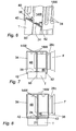
Fig. 7 is a cross sectional view of the manifold, where a fluid flow connection tube is inserted through the outer and inner walls of the manifold; and -
Fig. 8 is a further cross sectional view of the arrangement inFig. 8 taken further along the longitudinal axis of the manifold. -
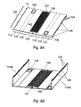
Fig. 9A is a perspective view of a second embodiment of the manifold, in its initial unfolded configuration. ; -
Fig. 9B shows the manifold ofFig. 3A after a first folding step; -
Fig. 9C shows the manifold after a second folding step; -
Fig. 9D shows the manifold after a third folding step; and -
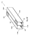
Fig. 9E shows the manifold in its final folded configuration after a fourth folding step. - With particular reference to
Fig. 1A , in its initial unfolded configuration, the heat exchanger manifold comprises a sheet ofbase material 12 that is easily manipulated into the finished article and is suitably strong to withstand the environments it will be subjected to in use. An example of a suitable material is a sheet of aluminium alloy. - The
sheet 12 is divided into first and secondpartition wall portions 14, first and second uppermanifold wall portions 16, first and secondside wall portions 18 andcentral portion 20. Division of the sheet may be assisted by the provision of discontinuities, such as score lines, formed in the surface of thesheet 12. -
Opposed edges 22 have a series ofshort protrusions 24 and elongatedprotrusions 26 formed thereon. Theprotrusions - First and second
partition wall portions 14 are each provided with fluidflow tube apertures 28 stamped therethrough.Side wall portion 18 is also provided with a corresponding fluidflow tube aperture 30 as well astube aperture 32. Strengthening ribs 34 (seeFig 2E ) are provided in the remaining space between theapertures side wall portion 18 and along the entire length of the opposingside wall portion 18. Theapertures -
Central portion 20 of thesheet 12 is formed with a series oftube insertion slots 36. As seen inFigs. 3 to 8 , the tube insertion slots have a pair ofopposed ledges 38 which protrude from thebase sheet 12 to form theslot 36 therebetween, in which heat exchanger tubes T may be received. As well as defining theslot 36, theopposed ledges 38 also define locating channels 40 (Fig. 1 B) on thebase sheet material 12 between the ledges. As seen inFig. 6, 7 and 8 , in this first embodiment, the series oftube insertion slots 36 do not span across the entire width of thecentral portion 20; to the contrary,side lips 42 are provided along either edge of thecentral portion 20 between either edge of theslots 36 and the adjacentside wall portions 18. Alongitudinal locating groove 21 is also provided alongcentral portion 20. - With reference to
Fig. 1D , thelongitudinal locating groove 21 has regularly spaced mountingholes 44 which are of a shape and size which corresponds with the combined shape and size of the regularly spacedelongated protrusions 26 of the ridged edges 22. - With the exception of strengthening
ridges 34 and the locatinggroove 21, all of the above features are formed by stamping through the sheet ofbase material 12 with a stamping tool. Furthermore, certain features may also be formed by an extrusion process; for example, theapertures The strengthening ridges 34 and locatinggroove 21 are formed by partially extruding portions of the base sheet in order to form indentations in the material wall without cutting there through. - Once the features previously described have been stamped on the base sheet of
material 12, thepartition wall portions 14, uppermanifold wall portions 16 and theside wall portions 18 are sequentially folded toward thecentral portion 20 in order to form the manifold 10 shown inFigs. 2 - 8 (this folding sequence is best described subsequently in relation to a second embodiment of the invention, although substantially the same sequence applies to this first embodiment). - It can be seen from the previous description and the drawings that the interior of the manifold 10 is divided by the
partition walls 14W into a firstlongitudinal chamber 46 and a second longitudinal chamber 48 (one being for fluid flow into the manifold and the other being fro fluid flow out of the manifold). In the foldedmanifold 10,aperture 30 inside wall 18W and the pair ofapertures 28 in thepartition walls 14W align with one another to provide a passage through which a fluid flow tube F may pass throughchamber 46 and directly intochamber 48. - When folding the walls of the
sheet 12 together, as thepartition walls 14W approach their final position their faces begin to abut against one another and the series ofshort protrusions 24 rest within the locatinggroove 21 of the corresponding series ofchannels 40 between theopposed ledges 38. Furthermore, theelongated protrusions 26 of eachridged edge 22 pass into the mounting holes 44. In this regard, as seen inFig. 4 , theelongated protrusions 26 may also be provided with an angled point in order to facilitate insertion into the mounting holes 44. - In this folded configuration, the web of the
partition walls 14W between theshort protrusions 24 abut against the thin edge of eachledge 38 and the outer edge of eachprotrusion 24 abuts against the trough of the inner walls of the locatingchannels 40 andgroove 21. When the manifold 10 is to be incorporated into a heat exchanger, heat exchanger tubes T are inserted into each of theslots 36 until their respective ends abut against the lower edge of thepartition walls 14W spanning thetube insertion slots 36. Each heat exchanger tube T has its own partition web along its internal bore (evidenced by seam 50) such that the portion of tube T on one side ofseam 50 is in isolated fluid communication withchamber 48 and the portion on the other side ofseam 50 is in isolated fluid communication withchamber 46. - The previously described arrangement has a geometry which provides superior brazing properties as follows:
- The upper and
lower ledges 38 of theslots 36 provide a flat surface which can be brazed to the outer wall of each tube T. When brazing it is desirable to, at least partially, cover theseam 50 of tubes T. Since tubes T are typically inserted into the manifold either way around (i.e. with the seam on one side or the other), there could otherwise be a risk that this requirement is not fulfilled; however, the presence of the upper and lower ledge ensures this. - The series of
short protrusions 24 sit snugly in thegroove 21 within the series ofchannels 40 and allow brazing along all sides thereof. - The
side lips 42 along the edge of theslots 36 allow theside walls 18 to be bent up from the plane of thebase sheet 12 until they are very close to the tubes T. Indeed, the tubes T may be brazed directly to theside walls 18W to improve the overall structural rigidity of the manifold. - The separating web along the
seam 50 of the tube T can be brazed to the edges of thepartition walls 14W to provide a structural bond as well as a fluid tight seal therebetween. - A second embodiment of the invention is shown in
Figs. 9A to 9E . The second embodiment of the invention is substantially similar to the first and has substantially the same advantages, with the exception of theapertures 128 which are, in this second embodiment, oval shaped and provided on theupper manifold wall 116W rather than through the sidemanifold walls 118W. - The sequence of folding the sheet of base material 112 to form the
manifold 110 of the second embodiment will now be described, although it will be appreciated that this sequence is equally applicable to the manifold of the first embodiment. - Starting from the planar sheet of base material 112 having the stamped features provided thereon, in a first folding step, the first and second
partition wall portions 114 are folded toward thecentral portion 120 at approximately 90 degrees from the plane of the sheet of material to formpartition walls 114W. - In a second folding step, the first and second upper
manifold wall portions 116, along with the previously foldedpartition walls 114W, are folded toward thecentral portion 120 at approximately 90 degrees from the plane of the sheet of material to form first and secondupper manifold walls 116W and hence the partially closed box depicted inFig. 9C . - In a third folding step, the first and second
side wall portions 118, along with the previously foldedpartition walls 114W and previously folded first and secondupper manifold walls 116W, are folded toward thecentral portion 120 as depicted inFig. 9D . In this third and final folding step, as the ridged edges 22 of thepartition walls 114W approach thecentral portion 120, theshort protrusions 124 are meshed into thegroove 121 in thechannels 140 between theopposed ledges 136. At the same time, theelongated protrusions 126 of each opposed ridgededge 22 are jointly inserted into the mountingholes 44 to secure the manifold 10 in its final closed configuration depicted byFig. 9E . - In use, the manifolds of the present invention provide first and second inlet / outlet chambers which have a series of single heat exchanger tube insertion slots for both chambers and which provide optimum brazing properties. The invention also improves the heat distribution, reduce the part count and complexity of the manifold over previous arrangements and minimises the likelihood of fluid leaks.
- Modifications and improvement may be made to the foregoing, without departing from the scope of the invention.
Claims (11)
- A method of forming a heat exchanger manifold from a sheet of base material, the method comprising:providing the sheet of base material (12; 112) with first and second partitioning wall portions (14; 114), first and second upper wall portions (16; 116), first and second side wall portions (18; 118) and a central portion (20; 120);forming a longitudinal locating groove (21; 121) in the central portion (20; 120) of the base material (12; 112);forming a series of tube insertion slots (36; 136) across the longitudinal locating groove of the base material (12; 112), each tube insertion slot having extruded walls (38; 138) which create locating channels (40; 140) between corresponding walls (38; 138) of adjacent tube insertion slots (36; 136);forming a series of protrusions (24; 124) along opposed edges of the first and second partitioning wall portions (14; 114) to form ridged edges (22; 122) thereon, the series of protrusions (24; 124) being positioned along the ridged edges (22; 122) to correspond with portions of the longitudinal locating groove (21; 121) and series of channels (40; 140) of the central portion (20; 120);folding the ridged edges (22; 122) of the first and second partitioning wall portions (14; 114) toward the central portion (20; 120) in order to form first and second partition walls (14W; 114W);folding the first and second upper wall portions (16; 116), and first and second partition walls (14W; 114W) toward the central portion (20; 120) to form first and second upper walls (16W; 116W);folding the first and second side wall portions (18;118), the first and second upper walls (16W; 116W), and the first and second partition walls (14W; 114W) toward the central portion (20; 120) to form first and second side walls (18W; 118W);folding the first and second side walls (18W; 118W), first and second upper walls (16W; 116W), and first and second partition walls (14W; 114W) towards the central portion (20; 120);locating the protrusions (24; 124) of the ridged edges (22; 122) in the longitudinal locating groove (21; 121) of the channels (40; 140) between the series of tube insertion slots (36; 136); andbrazing the protrusions (24; 124) of the ridged edges (22; 122) to the walls of the channels (40; 140) in the longitudinal groove (21; 121).
- A method of forming a heat exchanger manifold according to claim 1, further comprising providing each tube insertion slot (36; 136) with a pair of opposed extruded walls (38; 138).
- A method of forming a heat exchanger manifold according to claim 2, further comprising:inserting a series of heat exchanger tubes (T), into the tube insertion slots (36; 136), the heat exchanger tubes (T) having a web member which divides their internal bore into a first and second fluid flow chamber;brazing the web member to edges of the partitioning walls (14W; 114W) between the protrusions (24; 124); andbrazing opposite external faces of the heat exchanger tubes (T) to the pair of opposed extruded walls (38; 138).
- A method of forming a heat exchanger manifold according to any preceding claim, further comprising:forming a series of elongated protrusions (26; 126) along the ridged edges (22; 122);forming a series of mounting holes (44; 144) in the longitudinal groove (21; 121), andlocating the elongated protrusions (26; 126) of each ridged edge (22; 122) in the mounting holes (44; 144).
- A heat exchanger manifold formed from a sheet of base material, the heat exchanger manifold comprising:folded first and second partition walls (14W; 114W);folded first and second upper walls (16W; 116W);folded first and second side walls (18W; 118W);a central base portion (20; 120) having a longitudinal locating groove (21; 121);a series of tube insertion slots (36; 136) in the central base portion (20; 120), each tube insertion slot having extruded walls (38; 138) which create locating channels (40; 140) between corresponding walls (38; 138) of adjacent tube insertion slots (36; 136);a series of protrusions (24; 124) along opposed edges of the first and second partitioning wall portions (14; 114) which form ridged edges (22; 122) thereon, the series of protrusions (24; 124) being positioned along the ridged edges (22; 122) to correspond with portions of the longitudinal locating groove (21; 121) and series of channels (40; 140) of the central base portion (20; 120);wherein the protrusions (24; 124) of the ridged edges (22; 122) are located in the groove (21; 121) of the channels (40; 140) between the series of tube insertion slots (36; 136) and are brazed thereto.
- A heat exchanger manifold according to claim 5, wherein each tube insertion slot (36; 136) comprises a pair of opposed extruded walls (38; 138).
- A heat exchanger manifold according to claim 6, wherein a series of heat exchanger tubes (T) are located in the tube insertion slots (36; 136), the heat exchanger tubes (T) having a web member which divides their internal bore into a first and second fluid flow chamber; and wherein the web member is brazed to edges of the partitioning walls (14W; 114W) between the protrusions (24; 124) and opposite external faces of the heat exchanger tubes (T) are brazed to the pair of opposed extruded walls (38; 138).
- A heat exchanger manifold according to any of claims 5 to 7, further comprising a series of elongated protrusions (26; 126) along the ridged edges (22; 122) the series of elongated protrusion being located within a series of corresponding mounting holes (44; 144) in the longitudinal groove (21; 121).
- A heat exchanger manifold according to claims 5 to 8, wherein the series of tube insertion slots (36; 136) only span across a portion of the central base portion (20; 120) width thereby providing side lips (42; 142) along opposite longitudinal edges of the central portion (20; 120).
- A heat exchanger manifold according to either of claims 8 or 9,
wherein the elongated protrusions (26; 126) comprise angled ends in order to facilitate insertion into the mounting holes 44. - A heat exchanger manifold according to claims 5 to 10, wherein the walls (14W; 18W; 116W) of the heat exchanger are provided with fluid flow apertures (28; 128, 30, 32) formed therethrough.
Priority Applications (1)
| Application Number | Priority Date | Filing Date | Title |
|---|---|---|---|
| EP08152405A EP2098313A1 (en) | 2008-03-06 | 2008-03-06 | A heat exchanger manifold and method of forming a heat exchanger manifold |
Applications Claiming Priority (1)
| Application Number | Priority Date | Filing Date | Title |
|---|---|---|---|
| EP08152405A EP2098313A1 (en) | 2008-03-06 | 2008-03-06 | A heat exchanger manifold and method of forming a heat exchanger manifold |
Publications (1)
| Publication Number | Publication Date |
|---|---|
| EP2098313A1 true EP2098313A1 (en) | 2009-09-09 |
Family
ID=39673383
Family Applications (1)
| Application Number | Title | Priority Date | Filing Date |
|---|---|---|---|
| EP08152405A Withdrawn EP2098313A1 (en) | 2008-03-06 | 2008-03-06 | A heat exchanger manifold and method of forming a heat exchanger manifold |
Country Status (1)
| Country | Link |
|---|---|
| EP (1) | EP2098313A1 (en) |
Citations (5)
| Publication number | Priority date | Publication date | Assignee | Title |
|---|---|---|---|---|
| EP1191298A2 (en) * | 2000-09-20 | 2002-03-27 | Visteon Global Technologies, Inc. | Heat exchanger construction |
| WO2002079708A2 (en) * | 2001-03-29 | 2002-10-10 | Showa Denko K.K. | Header for use in heat exchangers, heat exchanger and method for manufacturing the same |
| WO2004005827A1 (en) | 2002-07-05 | 2004-01-15 | Behr Gmbh & Co. Kg | Heat exchanger in particular an evaporator for a vehicle air-conditioning unit |
| EP1526351A2 (en) * | 2003-10-24 | 2005-04-27 | Behr GmbH & Co. KG | Process for manufacturing a heat exchanger, and heat exchanger manufactured according to such a process |
| US20060283583A1 (en) * | 2005-06-17 | 2006-12-21 | Newfield Technology Corporation | Stamped manifold for a heat exchanger and method for making same |
-
2008
- 2008-03-06 EP EP08152405A patent/EP2098313A1/en not_active Withdrawn
Patent Citations (6)
| Publication number | Priority date | Publication date | Assignee | Title |
|---|---|---|---|---|
| EP1191298A2 (en) * | 2000-09-20 | 2002-03-27 | Visteon Global Technologies, Inc. | Heat exchanger construction |
| WO2002079708A2 (en) * | 2001-03-29 | 2002-10-10 | Showa Denko K.K. | Header for use in heat exchangers, heat exchanger and method for manufacturing the same |
| US20040182558A1 (en) | 2001-03-29 | 2004-09-23 | Futoshi Watanabe | Header for use in heat exchanger, heat exchanger and method for manufacturing the same |
| WO2004005827A1 (en) | 2002-07-05 | 2004-01-15 | Behr Gmbh & Co. Kg | Heat exchanger in particular an evaporator for a vehicle air-conditioning unit |
| EP1526351A2 (en) * | 2003-10-24 | 2005-04-27 | Behr GmbH & Co. KG | Process for manufacturing a heat exchanger, and heat exchanger manufactured according to such a process |
| US20060283583A1 (en) * | 2005-06-17 | 2006-12-21 | Newfield Technology Corporation | Stamped manifold for a heat exchanger and method for making same |
Similar Documents
| Publication | Publication Date | Title |
|---|---|---|
| US7740058B2 (en) | Plate heat exchanger | |
| EP2810010B1 (en) | Multiple tube bank heat exchanger assembly and fabrication method | |
| EP0532794B1 (en) | Manifold and heat exchanger assembly | |
| US4778004A (en) | Heat exchanger assembly with integral fin unit | |
| US7578340B2 (en) | Heat exchanger | |
| EP1181494B1 (en) | Clip on manifold heat exchanger | |
| EP2884209B1 (en) | Bent heat exchanger and method for bending the heat exchanger | |
| US5904206A (en) | Heat exchanger flow tube with improved header to tube end stress resistance | |
| US20060201663A1 (en) | Heat exchanger and flat tubes | |
| EP1884734A1 (en) | Heat exchanger assembly with partitioned manifolds | |
| US5209292A (en) | Condenser header and tank assembly with interference fit baffle | |
| US20030196785A1 (en) | Heat exchanger | |
| US9901966B2 (en) | Method for fabricating flattened tube finned heat exchanger | |
| EP2977706A1 (en) | Manifold and heat exchanger having same | |
| EP3971508B1 (en) | Heat exchanger | |
| EP0625687A2 (en) | Heat exchanger and manifold therefor, and method of assembly thereof | |
| KR20100023757A (en) | Manifold with multiple passages and cross-counterflow heat exchanger incorporating the same | |
| JPH0894285A (en) | Heat exchanger | |
| US6332495B1 (en) | Clip on manifold heat exchanger | |
| US20100108303A1 (en) | Heat exchanger construction | |
| JP2008224057A (en) | Heat exchanger, header tank of heat exchanger, and its manufacturing method | |
| CA2508684C (en) | Stacking-type, multi-flow, heat exchangers and methods for manufacturing such heat exchangers | |
| JP2004537028A (en) | High pressure manifold | |
| US4881311A (en) | Heat exchanger assembly with integral fin unit | |
| GB2371505A (en) | Heat exchanger construction |
Legal Events
| Date | Code | Title | Description |
|---|---|---|---|
| PUAI | Public reference made under article 153(3) epc to a published international application that has entered the european phase |
Free format text: ORIGINAL CODE: 0009012 |
|
| AK | Designated contracting states |
Kind code of ref document: A1 Designated state(s): AT BE BG CH CY CZ DE DK EE ES FI FR GB GR HR HU IE IS IT LI LT LU LV MC MT NL NO PL PT RO SE SI SK TR |
|
| AX | Request for extension of the european patent |
Extension state: AL BA MK RS |
|
| 17P | Request for examination filed |
Effective date: 20100309 |
|
| 17Q | First examination report despatched |
Effective date: 20100401 |
|
| AKX | Designation fees paid |
Designated state(s): AT BE BG CH CY CZ DE DK EE ES FI FR GB GR HR HU IE IS IT LI LT LU LV MC MT NL NO PL PT RO SE SI SK TR |
|
| RAP1 | Party data changed (applicant data changed or rights of an application transferred) |
Owner name: MAHLE INTERNATIONAL GMBH |
|
| STAA | Information on the status of an ep patent application or granted ep patent |
Free format text: STATUS: THE APPLICATION IS DEEMED TO BE WITHDRAWN |
|
| 18D | Application deemed to be withdrawn |
Effective date: 20180915 |