EP2098279A1 - Exhaust gas purification device for internal combustion engine - Google Patents
Exhaust gas purification device for internal combustion engine Download PDFInfo
- Publication number
- EP2098279A1 EP2098279A1 EP08020452A EP08020452A EP2098279A1 EP 2098279 A1 EP2098279 A1 EP 2098279A1 EP 08020452 A EP08020452 A EP 08020452A EP 08020452 A EP08020452 A EP 08020452A EP 2098279 A1 EP2098279 A1 EP 2098279A1
- Authority
- EP
- European Patent Office
- Prior art keywords
- oxygen
- storage material
- ion conductive
- conductive material
- exhaust gas
- Prior art date
- Legal status (The legal status is an assumption and is not a legal conclusion. Google has not performed a legal analysis and makes no representation as to the accuracy of the status listed.)
- Ceased
Links
Images



Classifications
-
- B—PERFORMING OPERATIONS; TRANSPORTING
- B01—PHYSICAL OR CHEMICAL PROCESSES OR APPARATUS IN GENERAL
- B01D—SEPARATION
- B01D53/00—Separation of gases or vapours; Recovering vapours of volatile solvents from gases; Chemical or biological purification of waste gases, e.g. engine exhaust gases, smoke, fumes, flue gases, aerosols
- B01D53/34—Chemical or biological purification of waste gases
- B01D53/92—Chemical or biological purification of waste gases of engine exhaust gases
- B01D53/94—Chemical or biological purification of waste gases of engine exhaust gases by catalytic processes
- B01D53/944—Simultaneously removing carbon monoxide, hydrocarbons or carbon making use of oxidation catalysts
-
- F—MECHANICAL ENGINEERING; LIGHTING; HEATING; WEAPONS; BLASTING
- F01—MACHINES OR ENGINES IN GENERAL; ENGINE PLANTS IN GENERAL; STEAM ENGINES
- F01N—GAS-FLOW SILENCERS OR EXHAUST APPARATUS FOR MACHINES OR ENGINES IN GENERAL; GAS-FLOW SILENCERS OR EXHAUST APPARATUS FOR INTERNAL-COMBUSTION ENGINES
- F01N3/00—Exhaust or silencing apparatus having means for purifying, rendering innocuous, or otherwise treating exhaust
- F01N3/02—Exhaust or silencing apparatus having means for purifying, rendering innocuous, or otherwise treating exhaust for cooling, or for removing solid constituents of, exhaust
-
- B—PERFORMING OPERATIONS; TRANSPORTING
- B01—PHYSICAL OR CHEMICAL PROCESSES OR APPARATUS IN GENERAL
- B01D—SEPARATION
- B01D53/00—Separation of gases or vapours; Recovering vapours of volatile solvents from gases; Chemical or biological purification of waste gases, e.g. engine exhaust gases, smoke, fumes, flue gases, aerosols
- B01D53/34—Chemical or biological purification of waste gases
- B01D53/92—Chemical or biological purification of waste gases of engine exhaust gases
- B01D53/94—Chemical or biological purification of waste gases of engine exhaust gases by catalytic processes
-
- B—PERFORMING OPERATIONS; TRANSPORTING
- B01—PHYSICAL OR CHEMICAL PROCESSES OR APPARATUS IN GENERAL
- B01J—CHEMICAL OR PHYSICAL PROCESSES, e.g. CATALYSIS OR COLLOID CHEMISTRY; THEIR RELEVANT APPARATUS
- B01J37/00—Processes, in general, for preparing catalysts; Processes, in general, for activation of catalysts
- B01J37/02—Impregnation, coating or precipitation
- B01J37/024—Multiple impregnation or coating
- B01J37/0244—Coatings comprising several layers
-
- F—MECHANICAL ENGINEERING; LIGHTING; HEATING; WEAPONS; BLASTING
- F01—MACHINES OR ENGINES IN GENERAL; ENGINE PLANTS IN GENERAL; STEAM ENGINES
- F01N—GAS-FLOW SILENCERS OR EXHAUST APPARATUS FOR MACHINES OR ENGINES IN GENERAL; GAS-FLOW SILENCERS OR EXHAUST APPARATUS FOR INTERNAL-COMBUSTION ENGINES
- F01N3/00—Exhaust or silencing apparatus having means for purifying, rendering innocuous, or otherwise treating exhaust
- F01N3/08—Exhaust or silencing apparatus having means for purifying, rendering innocuous, or otherwise treating exhaust for rendering innocuous
- F01N3/10—Exhaust or silencing apparatus having means for purifying, rendering innocuous, or otherwise treating exhaust for rendering innocuous by thermal or catalytic conversion of noxious components of exhaust
- F01N3/18—Exhaust or silencing apparatus having means for purifying, rendering innocuous, or otherwise treating exhaust for rendering innocuous by thermal or catalytic conversion of noxious components of exhaust characterised by methods of operation; Control
- F01N3/20—Exhaust or silencing apparatus having means for purifying, rendering innocuous, or otherwise treating exhaust for rendering innocuous by thermal or catalytic conversion of noxious components of exhaust characterised by methods of operation; Control specially adapted for catalytic conversion
-
- B—PERFORMING OPERATIONS; TRANSPORTING
- B01—PHYSICAL OR CHEMICAL PROCESSES OR APPARATUS IN GENERAL
- B01D—SEPARATION
- B01D2255/00—Catalysts
- B01D2255/20—Metals or compounds thereof
- B01D2255/206—Rare earth metals
-
- B—PERFORMING OPERATIONS; TRANSPORTING
- B01—PHYSICAL OR CHEMICAL PROCESSES OR APPARATUS IN GENERAL
- B01D—SEPARATION
- B01D2255/00—Catalysts
- B01D2255/20—Metals or compounds thereof
- B01D2255/207—Transition metals
- B01D2255/20715—Zirconium
-
- B—PERFORMING OPERATIONS; TRANSPORTING
- B01—PHYSICAL OR CHEMICAL PROCESSES OR APPARATUS IN GENERAL
- B01D—SEPARATION
- B01D2255/00—Catalysts
- B01D2255/40—Mixed oxides
- B01D2255/402—Perovskites
-
- B—PERFORMING OPERATIONS; TRANSPORTING
- B01—PHYSICAL OR CHEMICAL PROCESSES OR APPARATUS IN GENERAL
- B01D—SEPARATION
- B01D2255/00—Catalysts
- B01D2255/90—Physical characteristics of catalysts
- B01D2255/902—Multilayered catalyst
- B01D2255/9022—Two layers
-
- B—PERFORMING OPERATIONS; TRANSPORTING
- B01—PHYSICAL OR CHEMICAL PROCESSES OR APPARATUS IN GENERAL
- B01D—SEPARATION
- B01D2255/00—Catalysts
- B01D2255/90—Physical characteristics of catalysts
- B01D2255/908—O2-storage component incorporated in the catalyst
-
- B—PERFORMING OPERATIONS; TRANSPORTING
- B01—PHYSICAL OR CHEMICAL PROCESSES OR APPARATUS IN GENERAL
- B01D—SEPARATION
- B01D2255/00—Catalysts
- B01D2255/90—Physical characteristics of catalysts
- B01D2255/92—Dimensions
- B01D2255/9202—Linear dimensions
-
- B—PERFORMING OPERATIONS; TRANSPORTING
- B01—PHYSICAL OR CHEMICAL PROCESSES OR APPARATUS IN GENERAL
- B01D—SEPARATION
- B01D2257/00—Components to be removed
- B01D2257/70—Organic compounds not provided for in groups B01D2257/00 - B01D2257/602
- B01D2257/702—Hydrocarbons
-
- B—PERFORMING OPERATIONS; TRANSPORTING
- B01—PHYSICAL OR CHEMICAL PROCESSES OR APPARATUS IN GENERAL
- B01D—SEPARATION
- B01D2258/00—Sources of waste gases
- B01D2258/01—Engine exhaust gases
- B01D2258/012—Diesel engines and lean burn gasoline engines
-
- B—PERFORMING OPERATIONS; TRANSPORTING
- B01—PHYSICAL OR CHEMICAL PROCESSES OR APPARATUS IN GENERAL
- B01J—CHEMICAL OR PHYSICAL PROCESSES, e.g. CATALYSIS OR COLLOID CHEMISTRY; THEIR RELEVANT APPARATUS
- B01J23/00—Catalysts comprising metals or metal oxides or hydroxides, not provided for in group B01J21/00
- B01J23/002—Mixed oxides other than spinels, e.g. perovskite
-
- B—PERFORMING OPERATIONS; TRANSPORTING
- B01—PHYSICAL OR CHEMICAL PROCESSES OR APPARATUS IN GENERAL
- B01J—CHEMICAL OR PHYSICAL PROCESSES, e.g. CATALYSIS OR COLLOID CHEMISTRY; THEIR RELEVANT APPARATUS
- B01J23/00—Catalysts comprising metals or metal oxides or hydroxides, not provided for in group B01J21/00
- B01J23/10—Catalysts comprising metals or metal oxides or hydroxides, not provided for in group B01J21/00 of rare earths
-
- Y—GENERAL TAGGING OF NEW TECHNOLOGICAL DEVELOPMENTS; GENERAL TAGGING OF CROSS-SECTIONAL TECHNOLOGIES SPANNING OVER SEVERAL SECTIONS OF THE IPC; TECHNICAL SUBJECTS COVERED BY FORMER USPC CROSS-REFERENCE ART COLLECTIONS [XRACs] AND DIGESTS
- Y02—TECHNOLOGIES OR APPLICATIONS FOR MITIGATION OR ADAPTATION AGAINST CLIMATE CHANGE
- Y02A—TECHNOLOGIES FOR ADAPTATION TO CLIMATE CHANGE
- Y02A50/00—TECHNOLOGIES FOR ADAPTATION TO CLIMATE CHANGE in human health protection, e.g. against extreme weather
- Y02A50/20—Air quality improvement or preservation, e.g. vehicle emission control or emission reduction by using catalytic converters
Definitions
- the present invention relates to an exhaust gas purification device for an internal combustion engine. Specifically, it relates to art for trapping and removing PM (particulate matter) contained in exhaust gas of a diesel engine.
- DPF diesel particulate filter
- a trapping function decreases and also pressure loss increases. Consequently, a catalyst to promote the oxidation action of PM is supported on DPF and PM is oxidized (burned) and discharge in the form of carbon dioxide to remove PM, thereby DPF being regenerated.
- platinum has been widely adopted. Also, in order to achieve a stable oxidation reaction, it is common to add an oxygen storage material such as ceria or zirconia to the catalyst.
- the oxygen ion conductive material as above is poor in oxidation performance as compared with platinum and particularly at a high temperature region, there is a risk that carbon monoxide may be generated as a result of insufficient oxidation of PM.
- an exhaust gas purification device for an internal combustion engine provided in an exhaust passage of the internal combustion engine, comprising:
- the oxygen ion conductive material may have a film form covering a periphery of the oxygen storage material.
- a crack reaching the oxygen storage material in the oxygen ion conductive material may be formed on the oxygen ion conductive material.
- An outer diameter of the oxygen storage material may be 5 ⁇ m or less, and a thickness or an outer diameter of the oxygen ion conductive material may be 30% or less of the outer diameter of the oxygen storage material.
- a volume of the oxygen ion conductive material may be 3 times or less a volume of the oxygen storage material.
- the oxygen ion conductive material may be a perovskite type oxide.
- the emission amount of CO is remarkably low as compared with the cases of the first Comparative Example and the second Comparative Example and is almost zero, so that it is found that PM is completely burned. Moreover, the emission amount of CO + CO 2 is not decreased contrarily to the case of the related-art example (first Comparative Example) where the oxygen ion conductive material 6 is particulate and thus it is found that oxidation performance is sufficiently secured.
- the present embodiment has such a constitution that the oxygen ion conductive material 6 covers a periphery of the oxygen storage material 5, the volume of the oxidation catalyst 4 can be reduced as compared with the related-art example (first Comparative Example) where the oxygen ion conductive material 6 is particulate. Accordingly, pressure loss in DPF 3 can be reduced.
- an oxygen storage material 5 having a low heat resistance can be adopted when it is covered with an oxygen ion conductive material 6 having a high heat resistance, material costs can be reduced.
- the exhaust gas can directly come into contact with the oxygen storage material 5 in the present embodiment, the supply of oxygen from the exhaust gas to the oxygen storage material 5 becomes more efficient, so that oxidation ability in the oxidation catalyst 20 can be improved.
- the organic complex method is related art for forming a coating film from an aqueous solution containing a low-molecular-weight metal complex and an alkylamine. Specifically, an aqueous metal chloride solution is mixed with ethylenediamine tetraacetic acid, tributylamine, and an aqueous hydrogen peroxide solution to form a tributylammonium salt of a metal complex. Then, ethanol is added thereto and mixed to form an organic complex solution and the solution is subjected to flow coating and baked to form a thin film of a metal oxide.
- an oxidation catalyst wherein a thin-film oxygen ion conductive material covers a periphery of the oxygen storage material.
- the above second embodiment can be easily realized.
- the oxygen ion conductive material 6 homogeneously covers a periphery of the oxygen storage material 5 and a part of the oxygen storage material 5 may be exposed. By such a constitution, the supply of oxygen from the exhaust gas to the oxygen storage material 5 can be efficiently achieved as in the case of the above oxidation catalyst 20.
- the catalyst may be formed so that particulate oxygen ion conductive material 6 is supported around the oxygen storage material 5.
- the oxygen ion conductive material 6 is formed so as to be in surface contact with the oxygen storage material 5, the supply of oxygen between the oxygen storage material 5 and the oxygen ion conductive material 6 can be efficiently achieved.
- the oxygen ion conductive material 6 is not limited to the above perovskite type oxide.
- a substance which actively perform oxygen ion delivery such as a perovskite type oxide (laGaO 3 ) or an irregular pyrochlore oxide (Ln 2 Zn 2 O 7 ) can be adopted in the invention.
- particulate matter containing carbon as a main component trapped on a support is oxidized with oxygen supplied from an oxygen ion conductive material, discharged as carbon dioxide, and thus removed from the support. Since oxygen is supplied from an oxygen storage material to the oxygen ion conductive material, oxygen insufficiency in the oxygen ion conductive material is solved and continuous oxidative removal of the particulate matter becomes possible. Particularly, in the present application, since the oxygen ion conductive material is supported around the oxygen storage material in surface contact therewith, large contact area between the oxygen storage material and the oxygen ion conductive material is secured and oxygen is efficiently supplied from the oxygen storage material to the oxygen ion conductive material.
- the oxygen ion conductive material is formed in a film form that covers a periphery of the oxygen storage material, larger contact area between the oxygen storage material and the oxygen ion conductive material is secured and oxygen is more efficiently supplied from the oxygen storage material to the oxygen ion conductive material.
- exhaust gas can come into direct contact with the oxygen storage material by passing through cracks which reach the oxygen storage material, oxygen in the exhaust gas is efficiently supplied to the oxygen storage material. Therefore, even when oxygen is supplied from the oxygen storage material to the particulate matter through the oxygen ion conductive material, oxygen insufficiency can be suppressed.
- an oxidation catalyst which enables efficient supply of oxygen from the oxygen storage material to the oxygen ion conductive material.
- the oxygen storage material is an oxygen storage material having a geometric particulate shape, there can be realized an oxidation catalyst which enables efficient supply of oxygen from the oxygen storage material to the oxygen ion conductive material.
- a volume ratio of the oxygen storage material to the oxygen ion conductive material becomes suitable and there can be realized an oxidation catalyst which enables efficient supply of oxygen to the oxygen ion conductive material.
- the oxygen ion conductive material is a perovskite type oxide, there can be realized an exhaust gas purification device wherein costs are suppressed without using an expensive material such as platinum.
Landscapes
- Chemical & Material Sciences (AREA)
- Engineering & Computer Science (AREA)
- Chemical Kinetics & Catalysis (AREA)
- Combustion & Propulsion (AREA)
- Health & Medical Sciences (AREA)
- Oil, Petroleum & Natural Gas (AREA)
- Environmental & Geological Engineering (AREA)
- Analytical Chemistry (AREA)
- General Chemical & Material Sciences (AREA)
- Biomedical Technology (AREA)
- Organic Chemistry (AREA)
- General Engineering & Computer Science (AREA)
- Mechanical Engineering (AREA)
- Materials Engineering (AREA)
- Toxicology (AREA)
- Catalysts (AREA)
- Exhaust Gas Treatment By Means Of Catalyst (AREA)
- Exhaust Gas After Treatment (AREA)
- Processes For Solid Components From Exhaust (AREA)
- Filtering Materials (AREA)
Abstract
Description
- The present invention relates to an exhaust gas purification device for an internal combustion engine. Specifically, it relates to art for trapping and removing PM (particulate matter) contained in exhaust gas of a diesel engine.
- In a diesel engine, in order to trap and remove PM containing carbon as a main component contained in exhaust gas, DPF (diesel particulate filter) has been widely used as an exhaust gas purification device. Tn such DPF, when PM deposits, a trapping function decreases and also pressure loss increases. Consequently, a catalyst to promote the oxidation action of PM is supported on DPF and PM is oxidized (burned) and discharge in the form of carbon dioxide to remove PM, thereby DPF being regenerated. As the catalyst for use in PDF, platinum has been widely adopted. Also, in order to achieve a stable oxidation reaction, it is common to add an oxygen storage material such as ceria or zirconia to the catalyst.
- However, recently, since the price of platinum rises steeply, a material that may be substituted for platinum has been investigated as one countermeasure. For example, an oxygen ion conductive material such as a perovskite type oxide has been proposed (refer to
JP-A-2007-224747 - However, the oxygen ion conductive material as above is poor in oxidation performance as compared with platinum and particularly at a high temperature region, there is a risk that carbon monoxide may be generated as a result of insufficient oxidation of PM.
- It is therefore an object of the invention to provide an exhaust gas purification device for an internal combustion engine that uses an oxygen ion conductive material as a catalyst material and traps particulate matter in exhaust gas, in which a sufficient oxidation performance is obtained and discharge of carbon monoxide is suppressed.
- In order to achieve the object, according to the invention, there is provided an exhaust gas purification device for an internal combustion engine, provided in an exhaust passage of the internal combustion engine, comprising:
- a filter-shape carrier adapted to trap particulate matter in exhaust gas; and
- an oxidation catalyst supported on the filter-shape carrier and comprising:
- a particulate oxygen storage material; and
- an oxygen ion conductive material supported around the oxygen storage material in surface contact therewith.
- The oxygen ion conductive material may have a film form covering a periphery of the oxygen storage material.
- A crack reaching the oxygen storage material in the oxygen ion conductive material may be formed on the oxygen ion conductive material.
- An outer diameter of the oxygen storage material may be 5 µm or less, and a thickness or an outer diameter of the oxygen ion conductive material may be 30% or less of the outer diameter of the oxygen storage material.
- An outer diameter of the oxygen storage material may be a value represented by the following calculation expression:

- A volume of the oxygen ion conductive material may be 3 times or less a volume of the oxygen storage material.
- The oxygen ion conductive material may be a perovskite type oxide.
-
-
FIG. 1 is a schematic block diagram of an exhaust system of an engine to which an exhaust gas purification device of the invention is applied. -
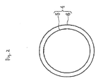
FIG. 2 is a schematic diagram showing the constitution of an oxidation catalyst according to the first embodiment of the invention. -
FIG. 3 is an enlarged view of a surface layer part of the oxidation catalyst. -
FIG. 4 is a graph showing combustion properties of PM in DPF. -
FIG. 5 is a schematic diagram showing the constitution of an oxidation catalyst of related art. -
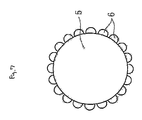
FIG. 6 is a schematic diagram showing the constitution of an oxidation catalyst according to the second embodiment of the invention. -
FIG. 7 is a schematic diagram showing the constitution of an oxidation catalyst according to the other embodiment of the invention. - The following will describe an embodiment of the invention based on drawings.
-
FIG. 1 is a schematic block diagram of an exhaust system of an engine (internal combustion engine) to which an exhaust gas purification device of the invention is applied.
Theengine 1 is a diesel engine andDPF 3 is fixed along anexhaust tube 2 of the engine.DPF 3 is, for example, formed with closing the upstream side and the downstream side of the passage of ahoneycomb carrier 3a alternatively with aplug 3b and has a function of trapping PM in exhaust gas. Thecarrier 3a has a porous structure formed of cordierite or the like and an oxidation catalyst is supported on the wall surface thereof to form an oxidation catalyst layer. -
FIG. 2 is a schematic diagram showing the constitution of anoxidation catalyst 4 according to the first embodiment of the invention. Theoxidation catalyst 4 supported on thecarrier 3a comprises anoxygen storage material 5 and an oxygen ionconductive material 6. Theoxygen storage material 5 has a function of occluding and discharging oxygen and, for example, a ceria compound such as CeO2, Ce-Zr-Bi, or Ce-Pr is used. The oxygen ionconductive material 6 is a substance having oxygen and capable of easy delivery from and to an adjacent substance and, for example, a perovskite type composite oxide containing an alkaline earth metal, such as LaSrMnO3, LaSrFeO3, LaBaFeO3, or LaBaMnO3 is used.
In the first embodiment of the invention, as shown inFIG. 2 , theoxidation catalyst 4 is formed so that the oxygen ionconductive material 6 covers a periphery of the particulateoxygen storage material 5 in a thin film form. It is preferred to adjust the diameter of theoxygen storage material 5 to about 5 µm, preferably about 1 to 2 µm and the thickness of the oxygen ionconductive material 6 to about 1% of the diameter of theoxygen storage material 5.
Moreover, in the case where the particle shape of the oxygen storage material is not spherical, it is suitable to use a value represented by an expression: volume ÷ particlesurface area x 6, as the outer diameter of the particle. As the volume, a true density determined by pycnometetry (gas phase substitution method) is used and, as the surface area, a specific surface area by the use of a BET method may be used. -
FIG. 3 is an enlarged view of a surface layer part of theoxidation catalyst 4.
InDPF 3 having theoxidation catalyst 4 of the above constitution, as shown inFIG. 3 , oxygen in the exhaust gas is occluded in theoxygen storage material 5 through the oxygen ionconductive material 6. On the other hand, PM 7 containing carbon as a main component attached to the surface of the oxygen ionconductive material 6 is oxidized with oxygen supplied from the oxygen ionconductive material 6. Therefore, PM 7 deposited onDPF 3 is discharged in the form of carbon dioxide and removed fromDPF 3. Moreover, oxygen in the oxygen ionconductive material 6 is consumed through the supply of oxygen from the oxygen ionconductive material 6 to PM but oxygen is supplied to the oxygen ionconductive material 6 from theoxygen storage material 5, so that oxygen deficiency is avoided and continuous oxidation becomes possible.
Since the present embodiment has a constitution that the oxygen ionconductive material 6 covers a periphery of theoxygen storage material 5, the contact area between theoxygen storage material 5 and the oxygen ionconductive material 6 is sufficiently secured and oxygen is efficiently supplied from theoxygen storage material 5 to the oxygen ionconductive material 6. Therefore, it is possible to prevent the incomplete oxidation of PM and to suppress the discharge of CO with sufficiently securing the oxidation function. -
FIG. 4 is a graph showing combustion properties of PM (carbon) inDPF 3. Specifically, it shows total discharged amounts of CO and CO2 according to catalyst temperature and discharged amounts of CO (component ratio in exhaust gas).
In the present graph, in addition to the above first embodiment, two kinds of combustion properties in DPF using related art are also shown as Comparative Examples.FIG. 5 is a schematic diagram showing a constitution of theoxidation catalyst 10 of related art that is first Comparative Example. As shown inFIG. 5 , in theoxidation catalyst 10 of the related art, not only theoxygen storage material 5 but also oxygen ionconductive material 6 have a particulate shape and theoxygen storage material 5 is in contact with the oxygen ionconductive material 6 but the contact area thereof is remarkably small as compared with the case of theoxidation catalyst 4 of the present embodiment. Therefore, it is difficult for theoxidation catalyst 10 to achieve efficient supply of oxygen between theoxygen storage material 5 and the oxygen ionconductive material 6. Second Comparative Example is the case where only the oxygen ionconductive material 6 is used as an oxidation catalyst. - As shown in
FIG. 4 , inDPF 3 of the present embodiment, even in a high temperature region, the emission amount of CO is remarkably low as compared with the cases of the first Comparative Example and the second Comparative Example and is almost zero, so that it is found that PM is completely burned. Moreover, the emission amount of CO + CO2 is not decreased contrarily to the case of the related-art example (first Comparative Example) where the oxygen ionconductive material 6 is particulate and thus it is found that oxidation performance is sufficiently secured.
Furthermore, since the present embodiment has such a constitution that the oxygen ionconductive material 6 covers a periphery of theoxygen storage material 5, the volume of theoxidation catalyst 4 can be reduced as compared with the related-art example (first Comparative Example) where the oxygen ionconductive material 6 is particulate. Accordingly, pressure loss inDPF 3 can be reduced. - Furthermore, in the present embodiment, since an
oxygen storage material 5 having a low heat resistance can be adopted when it is covered with an oxygen ionconductive material 6 having a high heat resistance, material costs can be reduced. -
FIG. 6 is a schematic diagram showing the constitution of theoxidation catalyst 20 according to the second embodiment of the invention.
In theoxidation catalyst 20 according to the second embodiment of the invention, cracks 21 are additionally formed at several portions on the oxygen ionconductive material 6 of theoxidation catalyst 4 of the first embodiment of the invention. The deepest parts of thecracks 21 reach theoxygen storage material 5. - By thus forming the cracks, since the exhaust gas can directly come into contact with the
oxygen storage material 5 in the present embodiment, the supply of oxygen from the exhaust gas to theoxygen storage material 5 becomes more efficient, so that oxidation ability in theoxidation catalyst 20 can be improved. - The following will describe a method of forming the
above oxidation catalysts - For forming the catalysts so that the oxygen ion
conductive material 6 covers a periphery of theoxygen storage material 5 as described in the above embodiments, it is possible to utilize an organic complex method. - The organic complex method is related art for forming a coating film from an aqueous solution containing a low-molecular-weight metal complex and an alkylamine. Specifically, an aqueous metal chloride solution is mixed with ethylenediamine tetraacetic acid, tributylamine, and an aqueous hydrogen peroxide solution to form a tributylammonium salt of a metal complex. Then, ethanol is added thereto and mixed to form an organic complex solution and the solution is subjected to flow coating and baked to form a thin film of a metal oxide. Thus, by utilizing the organic complex method, there can be easily produced an oxidation catalyst wherein a thin-film oxygen ion conductive material covers a periphery of the oxygen storage material.
- Moreover, when an organic substance such as polyethylene glycol is mixed with the complex solution, the organic substance burns at the baking and cracks can be formed in the oxygen ion conductive material. Thereby, the above second embodiment can be easily realized.
In this connection, it is not necessary that the oxygen ionconductive material 6 homogeneously covers a periphery of theoxygen storage material 5 and a part of theoxygen storage material 5 may be exposed. By such a constitution, the supply of oxygen from the exhaust gas to theoxygen storage material 5 can be efficiently achieved as in the case of theabove oxidation catalyst 20. - Furthermore, as shown in
FIG. 7 , the catalyst may be formed so that particulate oxygen ionconductive material 6 is supported around theoxygen storage material 5. In this case, when the oxygen ionconductive material 6 is formed so as to be in surface contact with theoxygen storage material 5, the supply of oxygen between theoxygen storage material 5 and the oxygen ionconductive material 6 can be efficiently achieved.
The oxygen ionconductive material 6 is not limited to the above perovskite type oxide. For example, a substance which actively perform oxygen ion delivery, such as a perovskite type oxide (laGaO3) or an irregular pyrochlore oxide (Ln2Zn2O7) can be adopted in the invention. - According to an aspect of the invention, particulate matter containing carbon as a main component trapped on a support is oxidized with oxygen supplied from an oxygen ion conductive material, discharged as carbon dioxide, and thus removed from the support. Since oxygen is supplied from an oxygen storage material to the oxygen ion conductive material, oxygen insufficiency in the oxygen ion conductive material is solved and continuous oxidative removal of the particulate matter becomes possible. Particularly, in the present application, since the oxygen ion conductive material is supported around the oxygen storage material in surface contact therewith, large contact area between the oxygen storage material and the oxygen ion conductive material is secured and oxygen is efficiently supplied from the oxygen storage material to the oxygen ion conductive material. Therefore, it becomes possible to achieve efficient oxidation of the particulate matter attached to the oxygen ion conductive material and hence incomplete oxidation of the particulate matter can be prevented even in a high-temperature region to suppress the discharge of carbon monoxide with sufficient removal of the particulate matter.
- According to an aspect of the invention, since the oxygen ion conductive material is formed in a film form that covers a periphery of the oxygen storage material, larger contact area between the oxygen storage material and the oxygen ion conductive material is secured and oxygen is more efficiently supplied from the oxygen storage material to the oxygen ion conductive material.
- According to an aspect of the invention, since exhaust gas can come into direct contact with the oxygen storage material by passing through cracks which reach the oxygen storage material, oxygen in the exhaust gas is efficiently supplied to the oxygen storage material. Therefore, even when oxygen is supplied from the oxygen storage material to the particulate matter through the oxygen ion conductive material, oxygen insufficiency can be suppressed.
- According to an aspect of the invention, there can be realized an oxidation catalyst which enables efficient supply of oxygen from the oxygen storage material to the oxygen ion conductive material.
According to an aspect of the invention, even when the oxygen storage material is an oxygen storage material having a geometric particulate shape, there can be realized an oxidation catalyst which enables efficient supply of oxygen from the oxygen storage material to the oxygen ion conductive material. - According to an aspect of the invention, a volume ratio of the oxygen storage material to the oxygen ion conductive material becomes suitable and there can be realized an oxidation catalyst which enables efficient supply of oxygen to the oxygen ion conductive material.
According to an aspect of the invention, since the oxygen ion conductive material is a perovskite type oxide, there can be realized an exhaust gas purification device wherein costs are suppressed without using an expensive material such as platinum.
Claims (7)
- An exhaust gas purification device for an internal combustion engine, provided in an exhaust passage of the internal combustion engine, comprising:a filter-shape carrier adapted to trap particulate matter in exhaust gas; andan oxidation catalyst supported on the filter-shape carrier and comprising:a particulate oxygen storage material; andan oxygen ion conductive material supported around the oxygen storage material in surface contact therewith.
- The exhaust gas purification device according to claim 1, wherein the oxygen ion conductive material has a film form covering a periphery of the oxygen storage material.
- The exhaust gas purification device according to claim 1 or 2, wherein a crack reaching the oxygen storage material in the oxygen ion conductive material is formed on the oxygen ion conductive material.
- The exhaust gas purification device according to claim 1, 2, or 3, wherein
an outer diameter of the oxygen storage material is 5 µm or less, and
a thickness or an outer diameter of the oxygen ion conductive material is 30% or less of the outer diameter of the oxygen storage material. - The exhaust gas purification device according to any one of the preceding claims, wherein
an outer diameter of the oxygen storage material is a value represented by the following calculation expression:
Outer Diameter of Oxygen Storage Material = Particle Volume V (cm3/g) ÷ Particle Surface Area S (cm2/g) x 6 - The exhaust gas purification device according to any one of the preceding claims, wherein a volume of the oxygen ion conductive material is 3 times or less a volume of the oxygen storage material.
- The exhaust gas purification device according to any one of the preceding claims, wherein the oxygen conductive material is a perovskite type oxide.
Applications Claiming Priority (1)
| Application Number | Priority Date | Filing Date | Title |
|---|---|---|---|
| JP2008038722A JP4784775B2 (en) | 2008-02-20 | 2008-02-20 | Exhaust gas purification device for internal combustion engine |
Publications (1)
| Publication Number | Publication Date |
|---|---|
| EP2098279A1 true EP2098279A1 (en) | 2009-09-09 |
Family
ID=40474861
Family Applications (1)
| Application Number | Title | Priority Date | Filing Date |
|---|---|---|---|
| EP08020452A Ceased EP2098279A1 (en) | 2008-02-20 | 2008-11-25 | Exhaust gas purification device for internal combustion engine |
Country Status (5)
| Country | Link |
|---|---|
| US (1) | US8137635B2 (en) |
| EP (1) | EP2098279A1 (en) |
| JP (1) | JP4784775B2 (en) |
| KR (1) | KR101086595B1 (en) |
| CN (1) | CN101514650B (en) |
Cited By (1)
| Publication number | Priority date | Publication date | Assignee | Title |
|---|---|---|---|---|
| KR101086595B1 (en) | 2008-02-20 | 2011-11-23 | 미쯔비시 지도샤 고교 가부시끼가이샤 | Exhaust gas purification device of internal combustion engine |
Families Citing this family (4)
| Publication number | Priority date | Publication date | Assignee | Title |
|---|---|---|---|---|
| JP5938819B2 (en) * | 2011-10-06 | 2016-06-22 | ジョンソン、マッセイ、パブリック、リミテッド、カンパニーJohnson Matthey Public Limited Company | Oxidation catalyst for exhaust gas treatment |
| US9666792B2 (en) * | 2015-08-12 | 2017-05-30 | Qualcomm Incorporated | Shadow-effect compensated fabrication of magnetic tunnel junction (MTJ) elements |
| US10900398B2 (en) * | 2018-05-15 | 2021-01-26 | Christopher Dean | Muffler filter |
| JP7857155B2 (en) * | 2022-05-11 | 2026-05-12 | 株式会社Subaru | Exhaust purifier |
Citations (7)
| Publication number | Priority date | Publication date | Assignee | Title |
|---|---|---|---|---|
| US20050255993A1 (en) * | 2002-07-09 | 2005-11-17 | Hiroshisa Tanaka | Method for producing catalyst for clarifying exhaust gas |
| WO2006021338A1 (en) * | 2004-08-21 | 2006-03-02 | Umicore Ag & Co. Kg | Method for coating a wall-flow filter with a coating composition |
| WO2006021337A1 (en) * | 2004-08-21 | 2006-03-02 | Umicore Ag & Co. Kg | Catalytically coated particle filter and method for producing the same and its use |
| WO2007058867A1 (en) * | 2005-11-10 | 2007-05-24 | Basf Catalysts Llc | Diesel particulate filters having ultra-thin catalyzed oxidation coatings |
| WO2007072690A1 (en) * | 2005-12-22 | 2007-06-28 | Cataler Corporation | Catalyst for exhaust gas clean-up |
| JP2007224747A (en) | 2006-02-21 | 2007-09-06 | Mitsubishi Motors Corp | Diesel engine exhaust gas purification filter and exhaust gas purification device |
| WO2007143837A1 (en) * | 2006-06-12 | 2007-12-21 | Nanox Inc. | Process for optimizing the catalytic activity of a perovskite-based catalyst |
Family Cites Families (11)
| Publication number | Priority date | Publication date | Assignee | Title |
|---|---|---|---|---|
| JPH04104838A (en) * | 1990-08-23 | 1992-04-07 | Matsushita Electric Ind Co Ltd | Waste gas purifying catalytic body |
| US6878354B1 (en) * | 1999-09-03 | 2005-04-12 | Mitsubishi Denki Kabushiki Kaisha | Catalyst and process for exhaust purification |
| CN1226090C (en) * | 2002-10-08 | 2005-11-09 | 康振川 | Composite rare earth hyperoxide with oxygen storage capacity and preparation and use thereof |
| JP3903925B2 (en) | 2003-02-13 | 2007-04-11 | 日産自動車株式会社 | Fuel property estimation device for internal combustion engine |
| WO2006080187A1 (en) * | 2005-01-31 | 2006-08-03 | Isuzu Motors Limited | Method of raising temperature of exhaust-gas purifier and exhaust-gas purification system |
| JP4618046B2 (en) * | 2005-08-23 | 2011-01-26 | マツダ株式会社 | Diesel particulate filter |
| JP2007209913A (en) * | 2006-02-10 | 2007-08-23 | Mazda Motor Corp | Catalyst material, production method thereof, and diesel particulate filter |
| FR2899493B1 (en) * | 2006-04-10 | 2008-05-23 | Saint Gobain Ct Recherches | PURIFICATION STRUCTURE INCORPORATING AN ELECTROCHEMICAL CATALYSIS SYSTEM |
| JP4849956B2 (en) | 2006-05-22 | 2012-01-11 | 株式会社東海 | Igniter |
| JP2009131774A (en) * | 2007-11-30 | 2009-06-18 | Nissan Motor Co Ltd | PM oxidation catalyst and exhaust gas purification catalyst using the same |
| JP4784775B2 (en) | 2008-02-20 | 2011-10-05 | 三菱自動車工業株式会社 | Exhaust gas purification device for internal combustion engine |
-
2008
- 2008-02-20 JP JP2008038722A patent/JP4784775B2/en not_active Expired - Fee Related
- 2008-11-24 CN CN2008101794046A patent/CN101514650B/en not_active Expired - Fee Related
- 2008-11-25 EP EP08020452A patent/EP2098279A1/en not_active Ceased
- 2008-11-25 US US12/323,173 patent/US8137635B2/en not_active Expired - Fee Related
- 2008-12-24 KR KR1020080133332A patent/KR101086595B1/en not_active Expired - Fee Related
Patent Citations (8)
| Publication number | Priority date | Publication date | Assignee | Title |
|---|---|---|---|---|
| US20050255993A1 (en) * | 2002-07-09 | 2005-11-17 | Hiroshisa Tanaka | Method for producing catalyst for clarifying exhaust gas |
| WO2006021338A1 (en) * | 2004-08-21 | 2006-03-02 | Umicore Ag & Co. Kg | Method for coating a wall-flow filter with a coating composition |
| WO2006021337A1 (en) * | 2004-08-21 | 2006-03-02 | Umicore Ag & Co. Kg | Catalytically coated particle filter and method for producing the same and its use |
| WO2007058867A1 (en) * | 2005-11-10 | 2007-05-24 | Basf Catalysts Llc | Diesel particulate filters having ultra-thin catalyzed oxidation coatings |
| WO2007072690A1 (en) * | 2005-12-22 | 2007-06-28 | Cataler Corporation | Catalyst for exhaust gas clean-up |
| EP1964607A1 (en) * | 2005-12-22 | 2008-09-03 | Cataler Corporation | Catalyst for exhaust gas clean-up |
| JP2007224747A (en) | 2006-02-21 | 2007-09-06 | Mitsubishi Motors Corp | Diesel engine exhaust gas purification filter and exhaust gas purification device |
| WO2007143837A1 (en) * | 2006-06-12 | 2007-12-21 | Nanox Inc. | Process for optimizing the catalytic activity of a perovskite-based catalyst |
Non-Patent Citations (2)
| Title |
|---|
| DATABASE WPI Week 200762, Derwent World Patents Index; AN 2007-663413, XP002522369 * |
| NEEFT ET AL: "Catalysts for the oxidation of soot from diesel exhaust gases II. Contact between soot and catalyst under practical conditions", APPLIED CATALYSIS B: ENVIRONMENTAL, ELSEVIER, vol. 12, no. 1, 16 May 1997 (1997-05-16), pages 21 - 31, XP022228181, ISSN: 0926-3373 * |
Cited By (1)
| Publication number | Priority date | Publication date | Assignee | Title |
|---|---|---|---|---|
| KR101086595B1 (en) | 2008-02-20 | 2011-11-23 | 미쯔비시 지도샤 고교 가부시끼가이샤 | Exhaust gas purification device of internal combustion engine |
Also Published As
| Publication number | Publication date |
|---|---|
| JP2009195797A (en) | 2009-09-03 |
| KR101086595B1 (en) | 2011-11-23 |
| CN101514650A (en) | 2009-08-26 |
| US20090208383A1 (en) | 2009-08-20 |
| JP4784775B2 (en) | 2011-10-05 |
| CN101514650B (en) | 2011-11-09 |
| US8137635B2 (en) | 2012-03-20 |
| KR20090090262A (en) | 2009-08-25 |
Similar Documents
| Publication | Publication Date | Title |
|---|---|---|
| US8257659B2 (en) | Prevention of face-plugging on aftertreatment devices in exhaust | |
| EP1837076B1 (en) | Diesel particulate filter catalyst with low no2 emissions | |
| US7797931B2 (en) | Catalyst composition for diesel particulate filter | |
| EP2363206B1 (en) | Particulate substance removing material, particulate substance removing filter catalyst using particulate substance removing material, and method for regenerating particulate substance removing filter catalyst | |
| EP3434356A1 (en) | Exhaust gas purification device | |
| EP3205388A1 (en) | Exhaust gas purification device | |
| EP2119491B1 (en) | Device for purification of exhaust gas | |
| JP5959147B2 (en) | Method for purifying exhaust gas of an internal combustion engine | |
| US9764287B2 (en) | Binary catalyst based selective catalytic reduction filter | |
| US20110271658A1 (en) | Nitrogen oxide storage catalytic converter for use in a motor vehicle in a close-coupled position | |
| JP4807129B2 (en) | Diesel particulate filter | |
| US8137635B2 (en) | Exhaust gas purification device for internal combustion engine | |
| CN101578432B (en) | Exhaust gas purifying apparatus for internal combustion engine | |
| EP3925681A1 (en) | Particulate filter | |
| CN114981000B (en) | Exhaust gas purification system | |
| US20050056977A1 (en) | Apparatus for removing carbon particles from an exhaust gas stream of internal combustion engines | |
| JP2011069326A (en) | Exhaust gas filter and exhaust gas treatment system using the same | |
| WO2021166699A1 (en) | Exhaust gas purification catalyst device | |
| JP2015047518A (en) | Particulate filter with catalyst and production method thereof | |
| JP5834924B2 (en) | Particulate filter with catalyst | |
| WO2020071389A1 (en) | Exhaust gas purification device | |
| EP4349483A1 (en) | Exhaust gas purification catalyst | |
| JP2020056382A (en) | Exhaust gas purification device | |
| JP7313314B2 (en) | Gas sensor element and gas sensor | |
| EP2941549B1 (en) | System for the post-treatment of exhaust gases |
Legal Events
| Date | Code | Title | Description |
|---|---|---|---|
| PUAI | Public reference made under article 153(3) epc to a published international application that has entered the european phase |
Free format text: ORIGINAL CODE: 0009012 |
|
| 17P | Request for examination filed |
Effective date: 20081223 |
|
| AK | Designated contracting states |
Kind code of ref document: A1 Designated state(s): AT BE BG CH CY CZ DE DK EE ES FI FR GB GR HR HU IE IS IT LI LT LU LV MC MT NL NO PL PT RO SE SI SK TR |
|
| AX | Request for extension of the european patent |
Extension state: AL BA MK RS |
|
| 17Q | First examination report despatched |
Effective date: 20100406 |
|
| AKX | Designation fees paid |
Designated state(s): DE FR |
|
| STAA | Information on the status of an ep patent application or granted ep patent |
Free format text: STATUS: THE APPLICATION HAS BEEN REFUSED |
|
| 18R | Application refused |
Effective date: 20121122 |