EP2098272A1 - Arrangement for splicing flat screen panels together for forming a cylindrical screen therewith - Google Patents
Arrangement for splicing flat screen panels together for forming a cylindrical screen therewith Download PDFInfo
- Publication number
- EP2098272A1 EP2098272A1 EP09250240A EP09250240A EP2098272A1 EP 2098272 A1 EP2098272 A1 EP 2098272A1 EP 09250240 A EP09250240 A EP 09250240A EP 09250240 A EP09250240 A EP 09250240A EP 2098272 A1 EP2098272 A1 EP 2098272A1
- Authority
- EP
- European Patent Office
- Prior art keywords
- rods
- panels
- screen
- joints
- bars
- Prior art date
- Legal status (The legal status is an assumption and is not a legal conclusion. Google has not performed a legal analysis and makes no representation as to the accuracy of the status listed.)
- Granted
Links
- 238000000034 method Methods 0.000 claims abstract description 21
- 238000003466 welding Methods 0.000 claims abstract description 9
- 238000005096 rolling process Methods 0.000 claims description 6
- 239000000463 material Substances 0.000 description 3
- QGZKDVFQNNGYKY-UHFFFAOYSA-N Ammonia Chemical compound N QGZKDVFQNNGYKY-UHFFFAOYSA-N 0.000 description 2
- PPBRXRYQALVLMV-UHFFFAOYSA-N Styrene Chemical compound C=CC1=CC=CC=C1 PPBRXRYQALVLMV-UHFFFAOYSA-N 0.000 description 2
- 238000001311 chemical methods and process Methods 0.000 description 2
- 239000002184 metal Substances 0.000 description 2
- 229910052751 metal Inorganic materials 0.000 description 2
- 150000002739 metals Chemical class 0.000 description 2
- 229910001220 stainless steel Inorganic materials 0.000 description 2
- 239000010935 stainless steel Substances 0.000 description 2
- 239000000126 substance Substances 0.000 description 2
- 230000004075 alteration Effects 0.000 description 1
- 229910021529 ammonia Inorganic materials 0.000 description 1
- 238000000429 assembly Methods 0.000 description 1
- 230000000712 assembly Effects 0.000 description 1
- 238000001833 catalytic reforming Methods 0.000 description 1
- 238000012993 chemical processing Methods 0.000 description 1
- 238000006243 chemical reaction Methods 0.000 description 1
- 238000006356 dehydrogenation reaction Methods 0.000 description 1
- 239000006185 dispersion Substances 0.000 description 1
- 238000001914 filtration Methods 0.000 description 1
- 239000007769 metal material Substances 0.000 description 1
- 238000012986 modification Methods 0.000 description 1
- 230000004048 modification Effects 0.000 description 1
- 230000035515 penetration Effects 0.000 description 1
- 238000012545 processing Methods 0.000 description 1
- 230000003014 reinforcing effect Effects 0.000 description 1
Images


Classifications
-
- B—PERFORMING OPERATIONS; TRANSPORTING
- B01—PHYSICAL OR CHEMICAL PROCESSES OR APPARATUS IN GENERAL
- B01D—SEPARATION
- B01D29/00—Filters with filtering elements stationary during filtration, e.g. pressure or suction filters, not covered by groups B01D24/00 - B01D27/00; Filtering elements therefor
- B01D29/44—Edge filtering elements, i.e. using contiguous impervious surfaces
- B01D29/445—Bar screens
-
- B—PERFORMING OPERATIONS; TRANSPORTING
- B01—PHYSICAL OR CHEMICAL PROCESSES OR APPARATUS IN GENERAL
- B01J—CHEMICAL OR PHYSICAL PROCESSES, e.g. CATALYSIS OR COLLOID CHEMISTRY; THEIR RELEVANT APPARATUS
- B01J8/00—Chemical or physical processes in general, conducted in the presence of fluids and solid particles; Apparatus for such processes
- B01J8/008—Details of the reactor or of the particulate material; Processes to increase or to retard the rate of reaction
- B01J8/0085—Details of the reactor or of the particulate material; Processes to increase or to retard the rate of reaction promoting uninterrupted fluid flow, e.g. by filtering out particles in front of the catalyst layer
-
- B—PERFORMING OPERATIONS; TRANSPORTING
- B01—PHYSICAL OR CHEMICAL PROCESSES OR APPARATUS IN GENERAL
- B01J—CHEMICAL OR PHYSICAL PROCESSES, e.g. CATALYSIS OR COLLOID CHEMISTRY; THEIR RELEVANT APPARATUS
- B01J8/00—Chemical or physical processes in general, conducted in the presence of fluids and solid particles; Apparatus for such processes
- B01J8/02—Chemical or physical processes in general, conducted in the presence of fluids and solid particles; Apparatus for such processes with stationary particles, e.g. in fixed beds
- B01J8/0207—Chemical or physical processes in general, conducted in the presence of fluids and solid particles; Apparatus for such processes with stationary particles, e.g. in fixed beds the fluid flow within the bed being predominantly horizontal
- B01J8/0214—Chemical or physical processes in general, conducted in the presence of fluids and solid particles; Apparatus for such processes with stationary particles, e.g. in fixed beds the fluid flow within the bed being predominantly horizontal in a cylindrical annular shaped bed
-
- B—PERFORMING OPERATIONS; TRANSPORTING
- B01—PHYSICAL OR CHEMICAL PROCESSES OR APPARATUS IN GENERAL
- B01J—CHEMICAL OR PHYSICAL PROCESSES, e.g. CATALYSIS OR COLLOID CHEMISTRY; THEIR RELEVANT APPARATUS
- B01J8/00—Chemical or physical processes in general, conducted in the presence of fluids and solid particles; Apparatus for such processes
- B01J8/02—Chemical or physical processes in general, conducted in the presence of fluids and solid particles; Apparatus for such processes with stationary particles, e.g. in fixed beds
- B01J8/0278—Feeding reactive fluids
-
- B—PERFORMING OPERATIONS; TRANSPORTING
- B07—SEPARATING SOLIDS FROM SOLIDS; SORTING
- B07B—SEPARATING SOLIDS FROM SOLIDS BY SIEVING, SCREENING, SIFTING OR BY USING GAS CURRENTS; SEPARATING BY OTHER DRY METHODS APPLICABLE TO BULK MATERIAL, e.g. LOOSE ARTICLES FIT TO BE HANDLED LIKE BULK MATERIAL
- B07B1/00—Sieving, screening, sifting, or sorting solid materials using networks, gratings, grids, or the like
- B07B1/18—Drum screens
-
- B—PERFORMING OPERATIONS; TRANSPORTING
- B07—SEPARATING SOLIDS FROM SOLIDS; SORTING
- B07B—SEPARATING SOLIDS FROM SOLIDS BY SIEVING, SCREENING, SIFTING OR BY USING GAS CURRENTS; SEPARATING BY OTHER DRY METHODS APPLICABLE TO BULK MATERIAL, e.g. LOOSE ARTICLES FIT TO BE HANDLED LIKE BULK MATERIAL
- B07B1/00—Sieving, screening, sifting, or sorting solid materials using networks, gratings, grids, or the like
- B07B1/46—Constructional details of screens in general; Cleaning or heating of screens
- B07B1/4609—Constructional details of screens in general; Cleaning or heating of screens constructional details of screening surfaces or meshes
- B07B1/4618—Manufacturing of screening surfaces
-
- B—PERFORMING OPERATIONS; TRANSPORTING
- B07—SEPARATING SOLIDS FROM SOLIDS; SORTING
- B07B—SEPARATING SOLIDS FROM SOLIDS BY SIEVING, SCREENING, SIFTING OR BY USING GAS CURRENTS; SEPARATING BY OTHER DRY METHODS APPLICABLE TO BULK MATERIAL, e.g. LOOSE ARTICLES FIT TO BE HANDLED LIKE BULK MATERIAL
- B07B1/00—Sieving, screening, sifting, or sorting solid materials using networks, gratings, grids, or the like
- B07B1/46—Constructional details of screens in general; Cleaning or heating of screens
- B07B1/4609—Constructional details of screens in general; Cleaning or heating of screens constructional details of screening surfaces or meshes
- B07B1/4681—Meshes of intersecting, non-woven, elements
-
- D—TEXTILES; PAPER
- D21—PAPER-MAKING; PRODUCTION OF CELLULOSE
- D21D—TREATMENT OF THE MATERIALS BEFORE PASSING TO THE PAPER-MAKING MACHINE
- D21D5/00—Purification of the pulp suspension by mechanical means; Apparatus therefor
- D21D5/02—Straining or screening the pulp
- D21D5/16—Cylinders and plates for screens
-
- B—PERFORMING OPERATIONS; TRANSPORTING
- B01—PHYSICAL OR CHEMICAL PROCESSES OR APPARATUS IN GENERAL
- B01J—CHEMICAL OR PHYSICAL PROCESSES, e.g. CATALYSIS OR COLLOID CHEMISTRY; THEIR RELEVANT APPARATUS
- B01J2208/00—Processes carried out in the presence of solid particles; Reactors therefor
- B01J2208/00796—Details of the reactor or of the particulate material
- B01J2208/00884—Means for supporting the bed of particles, e.g. grids, bars, perforated plates
Definitions
- FIG. 1 shows an example of a typical radial flow reactor vessel 10 for a chemical processing system.
- the vessel 10 includes a chamber 12 having an outer basket 20 and a centerpipe 30, although a variety of other configurations are known and used.
- Both the basket 20 and centerpipe 30 are composed of wires welded to rods to form a number of slot opening for filtering the radial process flow.
- the slot openings on both the centerpipe 30 and outer basket 20 can be oriented vertically to allow media to slide up and down during processing without becoming abraded by edges of the openings.
- the basket 20 and centerpipe 30 may be any height and diameter depending on the implementation, and the slot openings between the wires can be as small as 0.010 in. (0.25 mm) and can be increased by to 0.0004 in. (0.01 mm) increments to a desired width.
- FIGS. 2A-2B illustrate one arrangement 50 for splicing screen panels 40A-B together according to the prior art.
- each panel 40A-B has a number of wires 60 (also known as "V-wires") welded to a support rod 70A-B.
- assemblers weld a splice plate 80 composed of a comparable metal material at the joints between adjoining rods 70A-B to connect the panels 40A-B together.
- splicing panels 40A-B can be time consuming.
- the arrangement 50 of splice plates 80 has been found to hinder the assemblers ability to roll the spliced panels 40A-B to form a basket or centerpipe while readily maintaining the required cylindrical shape within acceptable tolerances.
- This resistance of the prior art spliced panels to roll into an ideal cylindrical shape is referred to as "peaking.” If the spliced screen panels 40A-B experience too much of this peaking during rolling, then the resulting cylindrical shape will likely be out of acceptable tolerances. Because baskets and centerpipes may be nested within one another, maintaining the cylindrical shape for the screen within acceptable tolerances can be important.
- Panels of a filter screen have a plurality of rods and a plurality of wires.
- the rods are arranged parallel to one another in a first direction.
- the wires are arranged parallel to one another and are attached in a perpendicular direction to the rods.
- the rods have jointed ends with a tab and a bevel along one edge of the panels and have flush ends along an opposite edge of the panels.
- the panels are connected together edge to edge in an elongated sheet by adjoining the jointed and the flush ends of the rods and then welding a plurality of splice bars alternatingly between adjacent ones of the rods at the joints.
- the elongated sheet is then rolled into a cylindrical tier that can be used as a portion of a basket, centerpipe or other cylindrical screen for a radial flow process or the like.
- FIG. 1 illustrates a radial flow reactor vessel as background of the present disclosure.
- FIG. 2A is a top view of a prior art arrangement for splicing screen panels together.
- FIG. 2B is a back view of the arrangement in FIG. 2A .
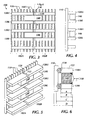
- FIG. 3 is an elevational view of an arrangement for splicing screen panels together according to the present disclosure.
- FIG. 4 is an end view of the arrangement in FIG. 3 .
- FIG. 5 is a perspective view of the arrangement in FIG. 3 .
- FIG. 6 is a cross-sectional view of the arrangement in FIG. 3 .
- FIG. 7 shows a plurality of screen panels and splice bars for assembly.
- FIG. 8 shows a detail of two adjoining screen panels spliced together by splice bars according to the present disclosure.
- FIG. 9 shows the screen panels joined as an elongated sheet.
- FIG. 10 shows the screen panels rolled into a cylindrically shaped tier.
- FIG. 11 shows several cylindrically shaped teirs connected together to form a cylindrical screen.
- FIGS. 3-6 illustrate an arrangement 100 according to the present disclosure for splicing screen panels 102A-B together to form a basket, centerpipe, or other screen for a chemical treatment process.
- portion of a first screen panel 102A is shown spliced together with portion of another screen panel 102B.
- Each of this panels 102A-B is first constructed as a planar screen having parallel wires 110 (e.g., "V-wires”) attached at their intersections to support rods 120 oriented in a perpendicular direction. Attachment of the wires 110 to the rods 120 can be performed by electric resistance welding, binding, or other technique. Once constructed, the panels 102A-B are adjoined one end to the other and spliced together.
- each splice bar 140 has a joint 130 above it formed by two adjoining upper support rods 120U on the adjacent panels 102A-B and has a joint 130 below it formed by two adjoining lower support rods 120L on the adjacent panels 102A-B.
- These joints 130 are created by a partial bevel 122 and a tab 124 formed on the ends of rods 120 along one of the panel's edges (e.g., panel 102B), as best shown in FIGS. 5 and 6 .
- each bar 140 is positioned so that its back edge is approximately flush with the back edge of the support rods 120U-L as shown in FIG. 6 .
- the square cross-section of the bar 140 with sides of depth A of about 0.63-inches fits in between the upper and lower bars 120U-L with only a small gap of about 0.03-inches between the bar 140 and rods 120U-L.
- the bar 140 fits over the space of the partial bevel 122 that has a depth B of about 0.75-inches, which is greater than the bar's depth A. In this way, the bar 140 is positioned a distance from the wires 110 by a space that is at least greater than the depth of the rods' tabs 124.
- each rod 120 is about 5/16-inches.
- the overall depth C of the rods 120 is about 1.00-inches, and the overall depth D of the assembly of rods 120 and wires 110 is about 1.17-inches.
- the length of the tab 124 i . e ., the width of each joint as viewed from the front as in FIG. 3 ) is about 0.19-inches.
- assemblers make square butt welds between the bars 140 and support rods 120U-L at locations 150 ( See FIGS. 3 and 6 ) to attach the splice bars 140 to the rods 120.
- Each of the butt welds at locations 150 runs the length of the back edge of the bars 140.
- These butt welds between bars 140 and rods 120 can be made using electric resistance welding or other technique.
- the assemblers make slot welds at locations 160 ( See FIGS. 3 and 6 ) between the tabs 124 and the flush ends of the support rods 120 at the joints 130. These slot welds at locations 160 are about 0.31-inches in width at the joints 130.
- These slot welds can use electric resistance welding or other technique and can use the splice bar 140 as backing for full penetration of the weld.
- assemblers can then form the panels into portion of a basket, centerpipe, or other screen for a chemical process. For example, stages of assembling a cylindrical screen portion are schematically shown in FIGS. 7 through 11 .
- assemblers create the plurality of planar screen panels 102A-D having the wires 110 and rods 120 discussed previously.
- Each of these screen panels 102A-D can be about 70-inches vertically ( i . e ., height of wires 110) and 100-inches horizontally ( i . e ., length of rods 120), although other dimensions can be used depending on the implementation.
- FIG. 8 shows a left screen panel 102A having an edge on which each of the support rods 120 has a flush end spliced to a right screen panel 102B having an edge on which each of the support rods 120 has a jointed end with the bevels 122 and tabs 124 discussed previously.
- Assemblers adjoin these edges together so that the ends of the rods 120 abut one another and weld the splice bars 140 alternatingly between adjacent ones of the rods 120 at the joints 130 using the techniques discussed previously.
- the splicing of adjoining ends of the screen panels 102A-D is repeated for several such panels 102 until assemblers make an elongated sheet 200 as shown in FIG. 9 .
- the elongated sheet 200 has an overall length of the desired circumference of the cylindrical screen to be formed.
- fives such screen panels 102A-E may be spliced together in this manner to make an elongated sheet 200 with a length of about 500-inches ( i . e ., about 41 2/3-ft.).
- the connected panels 102A-D are then rolled using rolling procedures known in the art.
- Use of the splice bars 140 and their connection to upper and lower support rods 120 at the splice joints 130 makes rolling the assembly of spliced panels 102 easier for assemblers to perform accurately.
- the arrangement 100 disclosed herein reduces the amount of "peaking" that occurs at the splice joints when assemblers roll the joined panels 102A-E into the cylindrical shape for the basket or centerpipe. "Peaking” refers to a tendency of the joined panels to resist forming an ideal cylindrical shape when being rolled. If the rolled screen panels 102A-E experience too much peaking, then the chance that the resulting cylindrical shape will be out of acceptable tolerance increases.
- Issues associated with peaking may be reduced with the present arrangement 100 for a number of reasons. For example, it is believed that the increased amount of material provided by the splice bars 140 helps disperse heat applied at the joints 130 when the bars 140 are welded to the support rods 120. The increased dispersion of heat may decrease the chances that the material properties of the bars 140 and rods 120 are altered or hardened during the welding process. Such hardening would result in greater resistance at the splice joints 130 to bend during the rolling process if it were not alleviate by the present arrangement 100.
- the elongated sheet 200 has been rolled into a cylindrical tier 210 as shown in FIG. 10 , and the two free ends of the rolled sheet 210 are spliced together using the splice bars 140 and techniques discussed previously.
- the sheet 210 may be rolled with the wider ends of the wires 110 positioned on the inner or outer diameter of the resulting cylindrical tier 210.
- Additional cylindrical tiers 210A-C can then be created in the same manner and stacked together using techniques known in the art to form a cylindrical screen 220 such as shown in FIG. 11 .
- This cylindrical screen 220 can then be used as part of a basket, centerpipe, or the like in a chemical treatment process.
- the cylindrical screen 220 can include top plates, reinforcing rods, and other structures known and used in the art for constructing a basket, centerpipe, or the like.
- an exemplary screen 220 can have 40 screen panels 102 with an overall height of about 46-ft.
- Such a screen 220 would have eight tiers 210 with each tier 210 made up of about five panels 102 spliced together.
- the wires 110 and rods 120 of the screen panels can be composed of 304, 316, or 321 stainless steel, although other metals may be used.
- a suitable wire includes the 130 size wire available from Johnson Screens
- a suitable rod includes the TE.313X1.00 rod available from Johnson Screens.
- the splice bars 140 can be composed of a comparable material, such as 304(h) stainless steel, although other metals may be used.
- the wires 110 can attach to the rods 120 and the panels can be rolled into a cylindrical shape using techniques such as disclosed in U.S. Pat. Nos. 2,046,458 ; 4,096,911 ; 4,276,265 ; 5,015,383 ; 5,118,419 ; and 6,785,964 , which are incorporated herein by reference in their entirety.
Landscapes
- Chemical & Material Sciences (AREA)
- Chemical Kinetics & Catalysis (AREA)
- Organic Chemistry (AREA)
- Engineering & Computer Science (AREA)
- Physics & Mathematics (AREA)
- Fluid Mechanics (AREA)
- Mechanical Engineering (AREA)
- Manufacturing & Machinery (AREA)
- Wire Processing (AREA)
- Filtration Of Liquid (AREA)
- Paper (AREA)
Abstract
Description
- Radial flow assemblies are used in chemical processes such as catalytic reforming, styrene dehydrogenation, ammonia conversion, and the like. In its simplest form, a radial flow assembly has two concentric screens with the annulus filled with treatment media. For example,
FIG. 1 shows an example of a typical radialflow reactor vessel 10 for a chemical processing system. Thevessel 10 includes achamber 12 having anouter basket 20 and acenterpipe 30, although a variety of other configurations are known and used. Both thebasket 20 andcenterpipe 30 are composed of wires welded to rods to form a number of slot opening for filtering the radial process flow. The slot openings on both thecenterpipe 30 andouter basket 20 can be oriented vertically to allow media to slide up and down during processing without becoming abraded by edges of the openings. Thebasket 20 andcenterpipe 30 may be any height and diameter depending on the implementation, and the slot openings between the wires can be as small as 0.010 in. (0.25 mm) and can be increased by to 0.0004 in. (0.01 mm) increments to a desired width. - To form the
basket 20 andcenterpipe 30, assemblers splice a number of screen panels together and roll the spliced screen panels to form the desired diameter of the resulting basket, centerpipe, or the like.FIGS. 2A-2B illustrate onearrangement 50 for splicing screen panels 40A-B together according to the prior art. As shown, each panel 40A-B has a number of wires 60 (also known as "V-wires") welded to asupport rod 70A-B. To splice the panels 40A-B together, assemblers weld asplice plate 80 composed of a comparable metal material at the joints between adjoiningrods 70A-B to connect the panels 40A-B together. - Because these
splice plates 80 must be welded at the numerous joints betweensupport rods 70A-V, splicing panels 40A-B can be time consuming. In addition, thearrangement 50 ofsplice plates 80 has been found to hinder the assemblers ability to roll the spliced panels 40A-B to form a basket or centerpipe while readily maintaining the required cylindrical shape within acceptable tolerances. This resistance of the prior art spliced panels to roll into an ideal cylindrical shape is referred to as "peaking." If the spliced screen panels 40A-B experience too much of this peaking during rolling, then the resulting cylindrical shape will likely be out of acceptable tolerances. Because baskets and centerpipes may be nested within one another, maintaining the cylindrical shape for the screen within acceptable tolerances can be important. - Panels of a filter screen have a plurality of rods and a plurality of wires. The rods are arranged parallel to one another in a first direction. The wires are arranged parallel to one another and are attached in a perpendicular direction to the rods. The rods have jointed ends with a tab and a bevel along one edge of the panels and have flush ends along an opposite edge of the panels. The panels are connected together edge to edge in an elongated sheet by adjoining the jointed and the flush ends of the rods and then welding a plurality of splice bars alternatingly between adjacent ones of the rods at the joints. The elongated sheet is then rolled into a cylindrical tier that can be used as a portion of a basket, centerpipe or other cylindrical screen for a radial flow process or the like.
- Additional details and information regarding the disclosed subject matter can be found in the following description and drawings.
-
FIG. 1 illustrates a radial flow reactor vessel as background of the present disclosure. -
FIG. 2A is a top view of a prior art arrangement for splicing screen panels together. -
FIG. 2B is a back view of the arrangement inFIG. 2A . -
FIG. 3 is an elevational view of an arrangement for splicing screen panels together according to the present disclosure. -
FIG. 4 is an end view of the arrangement inFIG. 3 . -
FIG. 5 is a perspective view of the arrangement inFIG. 3 . -
FIG. 6 is a cross-sectional view of the arrangement inFIG. 3 . -
FIG. 7 shows a plurality of screen panels and splice bars for assembly. -
FIG. 8 shows a detail of two adjoining screen panels spliced together by splice bars according to the present disclosure. -
FIG. 9 shows the screen panels joined as an elongated sheet. -
FIG. 10 shows the screen panels rolled into a cylindrically shaped tier. -
FIG. 11 shows several cylindrically shaped teirs connected together to form a cylindrical screen. -
FIGS. 3-6 illustrate anarrangement 100 according to the present disclosure for splicingscreen panels 102A-B together to form a basket, centerpipe, or other screen for a chemical treatment process. InFIG. 3 , for example, portion of afirst screen panel 102A is shown spliced together with portion ofanother screen panel 102B. Each of thispanels 102A-B is first constructed as a planar screen having parallel wires 110 (e.g., "V-wires") attached at their intersections to supportrods 120 oriented in a perpendicular direction. Attachment of thewires 110 to therods 120 can be performed by electric resistance welding, binding, or other technique. Once constructed, thepanels 102A-B are adjoined one end to the other and spliced together. - To splice the
panels 102A-B together,splice bars 140 are intermittently positioned atjoints 130 betweenadjacent support rods 120. Accordingly, eachsplice bar 140 has ajoint 130 above it formed by two adjoiningupper support rods 120U on theadjacent panels 102A-B and has ajoint 130 below it formed by two adjoininglower support rods 120L on theadjacent panels 102A-B. Thesejoints 130 are created by apartial bevel 122 and atab 124 formed on the ends ofrods 120 along one of the panel's edges (e.g.,panel 102B), as best shown inFIGS. 5 and 6 . - At these
joints 130, eachbar 140 is positioned so that its back edge is approximately flush with the back edge of thesupport rods 120U-L as shown inFIG. 6 . In one implementation, the square cross-section of thebar 140 with sides of depth A of about 0.63-inches fits in between the upper andlower bars 120U-L with only a small gap of about 0.03-inches between thebar 140 androds 120U-L. In addition, thebar 140 fits over the space of thepartial bevel 122 that has a depth B of about 0.75-inches, which is greater than the bar's depth A. In this way, thebar 140 is positioned a distance from thewires 110 by a space that is at least greater than the depth of the rods'tabs 124. The thickness of eachrod 120 is about 5/16-inches. The overall depth C of therods 120 is about 1.00-inches, and the overall depth D of the assembly ofrods 120 andwires 110 is about 1.17-inches. The length of the tab 124 (i.e., the width of each joint as viewed from the front as inFIG. 3 ) is about 0.19-inches. - At the
joints 130, assemblers make square butt welds between thebars 140 and supportrods 120U-L at locations 150 (SeeFIGS. 3 and 6 ) to attach thesplice bars 140 to therods 120. Each of the butt welds atlocations 150 runs the length of the back edge of thebars 140. These butt welds betweenbars 140 androds 120 can be made using electric resistance welding or other technique. In addition to the butt welds, the assemblers make slot welds at locations 160 (SeeFIGS. 3 and 6 ) between thetabs 124 and the flush ends of thesupport rods 120 at thejoints 130. These slot welds atlocations 160 are about 0.31-inches in width at thejoints 130. These slot welds can use electric resistance welding or other technique and can use thesplice bar 140 as backing for full penetration of the weld. - Once the
panels 102A-B have been spliced together with thesplice bars 140 according to the above techniques, assemblers can then form the panels into portion of a basket, centerpipe, or other screen for a chemical process. For example, stages of assembling a cylindrical screen portion are schematically shown inFIGS. 7 through 11 . Starting inFIG. 7 , assemblers create the plurality ofplanar screen panels 102A-D having thewires 110 androds 120 discussed previously. Each of thesescreen panels 102A-D can be about 70-inches vertically (i.e., height of wires 110) and 100-inches horizontally (i.e., length of rods 120), although other dimensions can be used depending on the implementation. - Assemblers then splice together adjoining ends of
adjacent screen panels 102A-D using the splice bars 104 according to the techniques discussed previously. For example,FIG. 8 shows aleft screen panel 102A having an edge on which each of thesupport rods 120 has a flush end spliced to aright screen panel 102B having an edge on which each of thesupport rods 120 has a jointed end with thebevels 122 andtabs 124 discussed previously. Assemblers adjoin these edges together so that the ends of therods 120 abut one another and weld the splice bars 140 alternatingly between adjacent ones of therods 120 at thejoints 130 using the techniques discussed previously. - The splicing of adjoining ends of the
screen panels 102A-D is repeated for several such panels 102 until assemblers make an elongated sheet 200 as shown inFIG. 9 . The elongated sheet 200 has an overall length of the desired circumference of the cylindrical screen to be formed. In one example, fivessuch screen panels 102A-E may be spliced together in this manner to make an elongated sheet 200 with a length of about 500-inches (i.e., about 41 2/3-ft.). - When
enough panels 102A-E are connected together to make up the desired circumference of a basket, a centerpipe, or the like, theconnected panels 102A-D are then rolled using rolling procedures known in the art. Use of the splice bars 140 and their connection to upper andlower support rods 120 at the splice joints 130 makes rolling the assembly of spliced panels 102 easier for assemblers to perform accurately. In particular, thearrangement 100 disclosed herein reduces the amount of "peaking" that occurs at the splice joints when assemblers roll the joinedpanels 102A-E into the cylindrical shape for the basket or centerpipe. "Peaking" refers to a tendency of the joined panels to resist forming an ideal cylindrical shape when being rolled. If the rolledscreen panels 102A-E experience too much peaking, then the chance that the resulting cylindrical shape will be out of acceptable tolerance increases. - Issues associated with peaking may be reduced with the
present arrangement 100 for a number of reasons. For example, it is believed that the increased amount of material provided by the splice bars 140 helps disperse heat applied at thejoints 130 when thebars 140 are welded to thesupport rods 120. The increased dispersion of heat may decrease the chances that the material properties of thebars 140 androds 120 are altered or hardened during the welding process. Such hardening would result in greater resistance at the splice joints 130 to bend during the rolling process if it were not alleviate by thepresent arrangement 100. - After performing the rolling process, the elongated sheet 200 has been rolled into a
cylindrical tier 210 as shown inFIG. 10 , and the two free ends of the rolledsheet 210 are spliced together using the splice bars 140 and techniques discussed previously. Depending on the desired arrangement and radial flow, thesheet 210 may be rolled with the wider ends of thewires 110 positioned on the inner or outer diameter of the resultingcylindrical tier 210. Additionalcylindrical tiers 210A-C can then be created in the same manner and stacked together using techniques known in the art to form acylindrical screen 220 such as shown inFIG. 11 . Thiscylindrical screen 220 can then be used as part of a basket, centerpipe, or the like in a chemical treatment process. Although only schematically shown inFIG. 11 , it will be appreciated that thecylindrical screen 220 can include top plates, reinforcing rods, and other structures known and used in the art for constructing a basket, centerpipe, or the like. In one example, anexemplary screen 220 can have 40 screen panels 102 with an overall height of about 46-ft. Such ascreen 220 would have eighttiers 210 with eachtier 210 made up of about five panels 102 spliced together. - In the present disclosure, the
wires 110 androds 120 of the screen panels can be composed of 304, 316, or 321 stainless steel, although other metals may be used. For example, a suitable wire includes the 130 size wire available from Johnson Screens, and a suitable rod includes the TE.313X1.00 rod available from Johnson Screens. The splice bars 140 can be composed of a comparable material, such as 304(h) stainless steel, although other metals may be used. In addition, thewires 110 can attach to therods 120 and the panels can be rolled into a cylindrical shape using techniques such as disclosed inU.S. Pat. Nos. 2,046,458 ;4,096,911 ;4,276,265 ;5,015,383 ;5,118,419 ; and6,785,964 , which are incorporated herein by reference in their entirety. - The foregoing description of preferred and other embodiments is not intended to limit or restrict the scope or applicability of the inventive concepts conceived of by the Applicants. In exchange for disclosing the inventive concepts contained herein, the Applicants desire all patent rights afforded by the appended claims. Therefore, it is intended that the appended claims include all modifications and alterations to the full extent that they come within the scope of the following claims or the equivalents thereof.
Claims (15)
- A filter screen, comprising:a plurality of rods arranged parallel to one another in a first direction, the rods having first and second ends and first and second edges, the first ends of at least some of the rods adjoining the second ends of at least some of the rods to form joints;a plurality of wires arranged parallel to one another in a second direction perpendicular to the first direction and attached to the first edges of the rods; anda plurality of bars alternatingly welded between adjacent ones of the rods at the joints.
- A filter screen assembly, comprising:a plurality of panels, each of the panels having -a plurality of rods arranged parallel to one another in a first direction, the rods having first and second ends and first and second edges;a plurality of wires arranged parallel to one another in a second direction perpendicular to the first direction and attached to the first edges of the rods,wherein a first of the panels has the first ends of its rods adjoining the second ends of the rods of a second of the panels at a plurality of joints; anda plurality of bars alternatingly positioned between adjacent ones of the rods at the joints, each of the bars welded to the adjacent rods.
- A screen, comprising:a plurality of cylindrical tiers stacked together, each of the tiers having a plurality of panels, each of the panels having -a plurality of rods arranged parallel to one another in a first direction, the rods having first and second ends and first and second edges;a plurality of wires arranged parallel to one another in a second direction perpendicular to the first direction and attached to the first edges of the rods,wherein the panels for each of the tiers have the first ends of the rods adjoining the second ends of the rods at a plurality of joints and a plurality of bars alternatingly positioned between adjacent ones of the rods at the joints, each of the bars welded to the adjacent rods.
- The screen of claim 1, 2, or 3, wherein the first ends of the rods each comprise a tab extending from the first end along the first edge such that the first end at the second edge defines a bevel.
- The screen of claim 4, wherein the second ends of the rods each define a flush surface.
- The screen of claim 4, wherein the tabs have slot welds with the second ends of the rod at the joints.
- The screen of claim 4, wherein each of the bars has a cross-section with a side dimension that is less than a depth of the bevel from the second edge of the rod.
- The screen of claim 1, 2, or 3, wherein each of the bars has a cross-section with a side dimension substantially equal to a distance separating the adjacent ones of the rods.
- The screen of claim 1, 2, or 3, wherein each of the bars has a square weld between the bar and the second edges of each of the adjacent ones of rods at the joints.
- The screen of claim 3, wherein the cylindrical screen comprises at least a portion of a basket or a centerpipe of a radial flow assembly.
- A filter screen assembly method, comprising:arranging parallel rods in a first direction,attaching parallel wires to the parallel rods in a second direction perpendicular to the first direction; andforming joints by adjoining jointed ends of at least some of the rods to flush ends of at least some of the rods; andwelding a plurality of bars alternatingly between adjacent ones of the rods at the joints.
- The method of claim 11, wherein arranging the parallel rods and attaching the parallel wires comprise forming a plurality of separate panels having a plurality of the parallel rods, each of the panels having the jointed ends of the rods along a first edge of the panel and the flush end of the rods along an opposite second edge of the panel.
- The method of claim 12, further comprising:adjoining the first and second edges of the separate panels together; andwelding the bars at the joints formed between the adjoining edges.
- The method of claim 12, further comprising forming a cylindrical tier by:forming an elongated sheet with the separate panels;rolling the elongated sheet into a cylindrical shape; andconnecting free ends of the rolled sheet by welding the bars alternatingly on the joints at the free ends.
- The method of claim 14, further comprising forming a cylindrical screen by stacking a plurality of the cylindrical tiers together.
Applications Claiming Priority (1)
| Application Number | Priority Date | Filing Date | Title |
|---|---|---|---|
| US12/035,273 US20090211965A1 (en) | 2008-02-21 | 2008-02-21 | Arrangement for splicing panels together to form a cylindrical screen |
Publications (2)
| Publication Number | Publication Date |
|---|---|
| EP2098272A1 true EP2098272A1 (en) | 2009-09-09 |
| EP2098272B1 EP2098272B1 (en) | 2011-04-13 |
Family
ID=40750941
Family Applications (1)
| Application Number | Title | Priority Date | Filing Date |
|---|---|---|---|
| EP09250240A Not-in-force EP2098272B1 (en) | 2008-02-21 | 2009-01-29 | Arrangement for splicing flat screen panels together for forming a cylindrical screen therewith |
Country Status (5)
| Country | Link |
|---|---|
| US (1) | US20090211965A1 (en) |
| EP (1) | EP2098272B1 (en) |
| JP (1) | JP4905732B2 (en) |
| AU (1) | AU2009200229B2 (en) |
| DE (1) | DE602009001022D1 (en) |
Cited By (3)
| Publication number | Priority date | Publication date | Assignee | Title |
|---|---|---|---|---|
| FR2966751A1 (en) * | 2010-10-28 | 2012-05-04 | IFP Energies Nouvelles | Radial bed reactor for regenerative reforming of species, skeletal isomerization, metathesis and oligocracking, comprises external cylindrical grid and coaxial internal cylindrical grid defining annular space containing catalyst bed |
| WO2016142035A1 (en) * | 2015-03-06 | 2016-09-15 | Andritz Fiedler Gmbh | Bar-type screen cage |
| US9924727B2 (en) | 2014-10-09 | 2018-03-27 | Safe Foods Corporation | Closed loop recycling system and dip tank for antimicrobial compounds |
Families Citing this family (10)
| Publication number | Priority date | Publication date | Assignee | Title |
|---|---|---|---|---|
| FR2937257A1 (en) * | 2008-10-21 | 2010-04-23 | Air Liquide | CONSTRUCTION METHOD APPLICABLE TO LARGE SIZE RADIAL ADSORBERS |
| US8439071B2 (en) * | 2011-05-27 | 2013-05-14 | Johnson Screens, Inc. | Screen basket vortex breaker for vessel |
| US9604164B2 (en) * | 2013-07-15 | 2017-03-28 | Aqseptence Group, Inc. | Fluid intake screen |
| KR101651756B1 (en) * | 2014-12-22 | 2016-08-29 | 주식회사 효성 | Catalyst screen with reinforced wires |
| KR101652597B1 (en) * | 2014-12-22 | 2016-08-31 | 주식회사 효성 | Catalyst screen with reinforced plates |
| FR3036977B1 (en) * | 2015-06-04 | 2021-01-29 | Hmds Process | RETAINING DEVICE FOR A CATALYST BED IN A CATALYTIC REACTOR |
| FR3056120B1 (en) * | 2016-09-20 | 2018-10-05 | Total Raffinage Chimie | CYLINDRICAL WALL FOR FILTERING SOLID PARTICLES IN A FLUID. |
| FR3056119B1 (en) * | 2016-09-20 | 2018-10-05 | Total Raffinage Chimie | CYLINDRICAL WALL FOR FILTERING SOLID PARTICLES IN A FLUID |
| GB201710924D0 (en) * | 2017-07-07 | 2017-08-23 | Johnson Matthey Davy Technologies Ltd | Radial-Flow Reactor Apparatus |
| CN110665806A (en) * | 2019-11-07 | 2020-01-10 | 刘西 | Polyurethane sieve plate structure |
Citations (14)
| Publication number | Priority date | Publication date | Assignee | Title |
|---|---|---|---|---|
| US2046458A (en) | 1934-11-10 | 1936-07-07 | Edward E Johnson Inc | Screen |
| US4096911A (en) | 1977-07-05 | 1978-06-27 | Uop Inc. | Channel base well screen |
| US4276265A (en) | 1979-12-26 | 1981-06-30 | Uop Inc. | Screen for collection and distribution of process streams |
| US4374729A (en) * | 1980-01-24 | 1983-02-22 | Ab Celleco | Strainer drum for pulp and the like |
| US4406326A (en) * | 1981-12-17 | 1983-09-27 | Uop Inc. | Plastic well screen and method of forming same |
| US5015383A (en) | 1989-06-15 | 1991-05-14 | Johnson Filtration Systems Inc. | Slotted screen scallops for high loading pressures and method of making same |
| US5069279A (en) * | 1990-07-05 | 1991-12-03 | Nagaoka Kanaami Kabushiki Kaisha | Well structure having a screen element with wire supporting rods |
| US5118419A (en) | 1989-06-15 | 1992-06-02 | Johnson Filtration Systems Inc. | Slotted scallop-shaped underdrain screened lateral elements |
| WO1995016819A1 (en) * | 1993-12-13 | 1995-06-22 | Cae Screenplates Inc. | Method of manufacturing a screen cylinder and a screen cylinder produced by the method |
| US5622625A (en) * | 1995-04-21 | 1997-04-22 | Nagaoka International Corp. | Method of manufacturing a drum |
| CA2178683A1 (en) * | 1995-10-25 | 1997-04-26 | Rejean Bouchard | A cylindric screen basket and a method of making same |
| EP0893536A2 (en) * | 1997-07-22 | 1999-01-27 | J&L Fiber Services, Inc. | Modular screen cylinder and a method for its manufacture |
| WO2001051168A1 (en) * | 2000-01-07 | 2001-07-19 | Kadant Black Clawson, Inc. | Wedge wire screen cylinder and method of manufacturing the same |
| US20030115754A1 (en) * | 2000-05-16 | 2003-06-26 | Reig Raphael | Method for making a mechanical screen cylinder |
Family Cites Families (33)
| Publication number | Priority date | Publication date | Assignee | Title |
|---|---|---|---|---|
| GB1472547A (en) * | 1973-12-11 | 1977-05-04 | Bekaert Sa Nv | Wire screens |
| FI57986C (en) * | 1979-02-28 | 1980-11-10 | Ahlstroem Oy | SILTRUMMA OCH SAETT ATT TILLVERKA DENNA |
| FR2572950B1 (en) * | 1984-11-12 | 1987-01-23 | Lamort E & M | IMPROVEMENTS ON SCREENS FOR CLEANERS AND THEIR MANUFACTURE |
| FR2612081B1 (en) * | 1987-03-13 | 1991-02-08 | Lamort E & M | IMPROVEMENT IN SCREENS FOR PURIFIER AND THEIR MANUFACTURE |
| US4819722A (en) * | 1988-01-19 | 1989-04-11 | Johnson Filtration Systems, Inc. | Metal well screen assembly with plastic end fitting and method of attaching same |
| DE3927748C2 (en) * | 1989-08-23 | 1994-03-10 | Voith Gmbh J M | Process for producing a screen basket and screen basket produced according to this method |
| CA2023408C (en) * | 1989-08-25 | 2001-03-13 | Terry Askew | Particle screening system |
| EP0432448B1 (en) * | 1989-12-09 | 1994-01-05 | Sulzer-Escher Wyss Gmbh | Process for making a wedge wire |
| US5047148A (en) * | 1990-04-24 | 1991-09-10 | Koichi Arai | Retained wire filter element |
| US5156738A (en) * | 1991-06-21 | 1992-10-20 | Johnson Filtration Systems Inc. | Apparatus for uniformly distributing gas and/or liquid in an underdrain lateral system |
| DE4121897A1 (en) * | 1991-07-02 | 1993-01-07 | Fiedler Heinrich Gmbh | SCREEN ELEMENT |
| US5387340A (en) * | 1993-07-15 | 1995-02-07 | Ackerman; Carl D. | Wire filter element and method of manufacture |
| US5611925A (en) * | 1994-03-23 | 1997-03-18 | Filtration Systems, Inc. | Hub ring and supporting plate for a filter and methods for manufacturing these members |
| DE4435538C2 (en) * | 1994-10-05 | 1996-10-02 | Voith Gmbh J M | Process for the production of a flat screen |
| US5718826A (en) * | 1995-05-26 | 1998-02-17 | Cae Screen Plates, Inc. | Screen and method of manufacture |
| FI100344B (en) * | 1995-11-28 | 1997-11-14 | Ahlstrom Machinery Oy | Process for making a sieve product and sieve product |
| US5791495A (en) * | 1996-03-11 | 1998-08-11 | Beloit Technologies, Inc. | Paper pulp screen cylinder |
| ATE210756T1 (en) * | 1996-05-24 | 2001-12-15 | Voith Sulzer Stoffaufbereitung | METHOD FOR PRODUCING A SCREENING DEVICE WITH GAP-SHAPED OPENINGS AND SCREENING DEVICE PRODUCED THEREFROM |
| JP3190254B2 (en) * | 1996-06-20 | 2001-07-23 | 相川鉄工株式会社 | Screen for papermaking |
| DE19635189C2 (en) * | 1996-08-30 | 1999-01-28 | Voith Sulzer Stoffaufbereitung | Process for the production of sieves |
| CN1080350C (en) * | 1996-10-03 | 2002-03-06 | Cae筛板公司 | Screening device, such as screen cylinder, and method of manufacture of screen device |
| DE19651643A1 (en) * | 1996-12-12 | 1998-06-18 | Voith Sulzer Stoffaufbereitung | Sieve for sorting out suspended fibres |
| US6089316A (en) * | 1997-08-01 | 2000-07-18 | Spray; Jeffery A. | Wire-wrapped well screen |
| JPH11156114A (en) * | 1997-11-26 | 1999-06-15 | Nippon Millipore Kk | Parallel flow cartridge filter |
| JP3286592B2 (en) * | 1997-12-25 | 2002-05-27 | 相川鉄工株式会社 | Screening equipment for papermaking |
| SE515006C2 (en) * | 1998-01-29 | 2001-05-28 | Gl & V Celleco Ab | Cylindrical screen and method of producing a cylindrical screen with formed projections |
| US6491168B1 (en) * | 2000-04-23 | 2002-12-10 | J + L Fiber Services, Inc. | Pulp screen basket |
| JP2001347108A (en) * | 2000-06-06 | 2001-12-18 | Aikawa Iron Works Co Ltd | Method of forming cylindrical screen and ring piece |
| FR2815073B1 (en) * | 2000-10-09 | 2002-12-06 | Johnson Filtration Systems | DRAIN ELEMENTS HAVING A CONSITIOUS STRAINER OF HOLLOW STEMS FOR COLLECTING, IN PARTICULAR, HYDROCARBONS |
| US6460757B1 (en) * | 2000-11-14 | 2002-10-08 | Newscreen As | Apparatus and method for forming slotted wire screens |
| JP2003010608A (en) * | 2001-07-05 | 2003-01-14 | Aikawa Iron Works Co Ltd | Cylindrical screen |
| GB0120862D0 (en) * | 2001-08-29 | 2001-10-17 | United Wire Ltd | Method and device for joining screens |
| US6761821B2 (en) * | 2002-09-23 | 2004-07-13 | Weatherford/Lamb, Inc. | Clamping-hook ring |
-
2008
- 2008-02-21 US US12/035,273 patent/US20090211965A1/en not_active Abandoned
-
2009
- 2009-01-22 AU AU2009200229A patent/AU2009200229B2/en not_active Ceased
- 2009-01-29 DE DE602009001022T patent/DE602009001022D1/en active Active
- 2009-01-29 EP EP09250240A patent/EP2098272B1/en not_active Not-in-force
- 2009-02-20 JP JP2009037707A patent/JP4905732B2/en not_active Expired - Fee Related
Patent Citations (15)
| Publication number | Priority date | Publication date | Assignee | Title |
|---|---|---|---|---|
| US2046458A (en) | 1934-11-10 | 1936-07-07 | Edward E Johnson Inc | Screen |
| US4096911A (en) | 1977-07-05 | 1978-06-27 | Uop Inc. | Channel base well screen |
| US4276265A (en) | 1979-12-26 | 1981-06-30 | Uop Inc. | Screen for collection and distribution of process streams |
| US4374729A (en) * | 1980-01-24 | 1983-02-22 | Ab Celleco | Strainer drum for pulp and the like |
| US4406326A (en) * | 1981-12-17 | 1983-09-27 | Uop Inc. | Plastic well screen and method of forming same |
| US5118419A (en) | 1989-06-15 | 1992-06-02 | Johnson Filtration Systems Inc. | Slotted scallop-shaped underdrain screened lateral elements |
| US5015383A (en) | 1989-06-15 | 1991-05-14 | Johnson Filtration Systems Inc. | Slotted screen scallops for high loading pressures and method of making same |
| US5069279A (en) * | 1990-07-05 | 1991-12-03 | Nagaoka Kanaami Kabushiki Kaisha | Well structure having a screen element with wire supporting rods |
| WO1995016819A1 (en) * | 1993-12-13 | 1995-06-22 | Cae Screenplates Inc. | Method of manufacturing a screen cylinder and a screen cylinder produced by the method |
| US5622625A (en) * | 1995-04-21 | 1997-04-22 | Nagaoka International Corp. | Method of manufacturing a drum |
| CA2178683A1 (en) * | 1995-10-25 | 1997-04-26 | Rejean Bouchard | A cylindric screen basket and a method of making same |
| EP0893536A2 (en) * | 1997-07-22 | 1999-01-27 | J&L Fiber Services, Inc. | Modular screen cylinder and a method for its manufacture |
| WO2001051168A1 (en) * | 2000-01-07 | 2001-07-19 | Kadant Black Clawson, Inc. | Wedge wire screen cylinder and method of manufacturing the same |
| US20030115754A1 (en) * | 2000-05-16 | 2003-06-26 | Reig Raphael | Method for making a mechanical screen cylinder |
| US6785964B2 (en) | 2000-05-16 | 2004-09-07 | Johnson Filtration Systems | Method for making a mechanical screen cylinder |
Cited By (4)
| Publication number | Priority date | Publication date | Assignee | Title |
|---|---|---|---|---|
| FR2966751A1 (en) * | 2010-10-28 | 2012-05-04 | IFP Energies Nouvelles | Radial bed reactor for regenerative reforming of species, skeletal isomerization, metathesis and oligocracking, comprises external cylindrical grid and coaxial internal cylindrical grid defining annular space containing catalyst bed |
| US9924727B2 (en) | 2014-10-09 | 2018-03-27 | Safe Foods Corporation | Closed loop recycling system and dip tank for antimicrobial compounds |
| WO2016142035A1 (en) * | 2015-03-06 | 2016-09-15 | Andritz Fiedler Gmbh | Bar-type screen cage |
| US10589196B2 (en) | 2015-03-06 | 2020-03-17 | Andritz Fiedler Gmbh | Bar-type screen cage |
Also Published As
| Publication number | Publication date |
|---|---|
| JP2009195902A (en) | 2009-09-03 |
| US20090211965A1 (en) | 2009-08-27 |
| EP2098272B1 (en) | 2011-04-13 |
| JP4905732B2 (en) | 2012-03-28 |
| AU2009200229B2 (en) | 2010-04-15 |
| AU2009200229A1 (en) | 2009-09-10 |
| DE602009001022D1 (en) | 2011-05-26 |
Similar Documents
| Publication | Publication Date | Title |
|---|---|---|
| AU2009200229B2 (en) | Arrangement for splicing panels together to form a cylindrical screen | |
| DE60317544T2 (en) | ARRANGEMENT OF CROSS-LINKED ELEMENTS AND METHOD FOR THE PRODUCTION THEREOF | |
| US10991472B2 (en) | Single-plate neutron absorbing apparatus and method of manufacturing the same | |
| DE2727032A1 (en) | HOLDING DEVICE FOR A LAYER OF PIPES INSIDE A CONTAINER | |
| DE19800943A1 (en) | Heating pipe for heat exchanger | |
| DE10393668T5 (en) | composite beam | |
| DE2818886B1 (en) | Core enclosure and process for their manufacture | |
| JPS61155992A (en) | Grating structure for fuel-rod integral canister | |
| JP3884133B2 (en) | Laminated metal filter | |
| AU2022269625B2 (en) | Centrifugal screen filter and related method of assembly | |
| JPS61155996A (en) | Nuclear fuel-rod transmission canister | |
| DE1559490B1 (en) | Reinforcement element for beams and supports made of reinforced concrete | |
| CN200992776Y (en) | Continuous stirrup | |
| JP3802039B2 (en) | Reinforcing bar connection structure and method for manufacturing reinforcing bar unit | |
| US9389027B2 (en) | Plate-type heat exchanger reactor and method for producing the same | |
| DE8027036U1 (en) | POLE DISCHARGE ELECTRODE | |
| DE102009003813A1 (en) | Reinforcing element, apparatus and method for producing a reinforcing element | |
| CN201003240Y (en) | Inverted T-shaped beam spiral hoop structure | |
| CN214461810U (en) | Wall body steel reinforcement cage | |
| EP0052164B1 (en) | Grid for placing elastic tubes or hoses | |
| DE102024003167B3 (en) | Battery module | |
| DE3044330A1 (en) | Underfloor heater element supporting mat - has adjacent chips for elements joined by straight lengths of bar | |
| CN210117987U (en) | Net device | |
| JP4693106B2 (en) | Formwork frame for rebar with positioning function | |
| JPH09915A (en) | Material and / or packing for heat exchange tower |
Legal Events
| Date | Code | Title | Description |
|---|---|---|---|
| PUAI | Public reference made under article 153(3) epc to a published international application that has entered the european phase |
Free format text: ORIGINAL CODE: 0009012 |
|
| 17P | Request for examination filed |
Effective date: 20090205 |
|
| AK | Designated contracting states |
Kind code of ref document: A1 Designated state(s): AT BE BG CH CY CZ DE DK EE ES FI FR GB GR HR HU IE IS IT LI LT LU LV MC MK MT NL NO PL PT RO SE SI SK TR |
|
| AX | Request for extension of the european patent |
Extension state: AL BA RS |
|
| 17Q | First examination report despatched |
Effective date: 20100406 |
|
| AKX | Designation fees paid |
Designated state(s): BE DE FR GB |
|
| GRAP | Despatch of communication of intention to grant a patent |
Free format text: ORIGINAL CODE: EPIDOSNIGR1 |
|
| GRAS | Grant fee paid |
Free format text: ORIGINAL CODE: EPIDOSNIGR3 |
|
| GRAA | (expected) grant |
Free format text: ORIGINAL CODE: 0009210 |
|
| AK | Designated contracting states |
Kind code of ref document: B1 Designated state(s): BE DE FR GB |
|
| REG | Reference to a national code |
Ref country code: GB Ref legal event code: FG4D |
|
| REF | Corresponds to: |
Ref document number: 602009001022 Country of ref document: DE Date of ref document: 20110526 Kind code of ref document: P |
|
| REG | Reference to a national code |
Ref country code: DE Ref legal event code: R096 Ref document number: 602009001022 Country of ref document: DE Effective date: 20110526 |
|
| PLBE | No opposition filed within time limit |
Free format text: ORIGINAL CODE: 0009261 |
|
| STAA | Information on the status of an ep patent application or granted ep patent |
Free format text: STATUS: NO OPPOSITION FILED WITHIN TIME LIMIT |
|
| 26N | No opposition filed |
Effective date: 20120116 |
|
| REG | Reference to a national code |
Ref country code: DE Ref legal event code: R097 Ref document number: 602009001022 Country of ref document: DE Effective date: 20120116 |
|
| PGFP | Annual fee paid to national office [announced via postgrant information from national office to epo] |
Ref country code: DE Payment date: 20140122 Year of fee payment: 6 Ref country code: BE Payment date: 20140123 Year of fee payment: 6 |
|
| PGFP | Annual fee paid to national office [announced via postgrant information from national office to epo] |
Ref country code: FR Payment date: 20140124 Year of fee payment: 6 |
|
| PGFP | Annual fee paid to national office [announced via postgrant information from national office to epo] |
Ref country code: GB Payment date: 20140129 Year of fee payment: 6 |
|
| PG25 | Lapsed in a contracting state [announced via postgrant information from national office to epo] |
Ref country code: BE Free format text: LAPSE BECAUSE OF NON-PAYMENT OF DUE FEES Effective date: 20150131 |
|
| REG | Reference to a national code |
Ref country code: DE Ref legal event code: R119 Ref document number: 602009001022 Country of ref document: DE |
|
| GBPC | Gb: european patent ceased through non-payment of renewal fee |
Effective date: 20150129 |
|
| PG25 | Lapsed in a contracting state [announced via postgrant information from national office to epo] |
Ref country code: DE Free format text: LAPSE BECAUSE OF NON-PAYMENT OF DUE FEES Effective date: 20150801 Ref country code: GB Free format text: LAPSE BECAUSE OF NON-PAYMENT OF DUE FEES Effective date: 20150129 |
|
| REG | Reference to a national code |
Ref country code: FR Ref legal event code: ST Effective date: 20150930 |
|
| PG25 | Lapsed in a contracting state [announced via postgrant information from national office to epo] |
Ref country code: FR Free format text: LAPSE BECAUSE OF NON-PAYMENT OF DUE FEES Effective date: 20150202 |