EP2098112A1 - Assembly for and method of grazing - Google Patents
Assembly for and method of grazing Download PDFInfo
- Publication number
- EP2098112A1 EP2098112A1 EP09075086A EP09075086A EP2098112A1 EP 2098112 A1 EP2098112 A1 EP 2098112A1 EP 09075086 A EP09075086 A EP 09075086A EP 09075086 A EP09075086 A EP 09075086A EP 2098112 A1 EP2098112 A1 EP 2098112A1
- Authority
- EP
- European Patent Office
- Prior art keywords
- holders
- grazing
- area
- delimiting
- cattle
- Prior art date
- Legal status (The legal status is an assumption and is not a legal conclusion. Google has not performed a legal analysis and makes no representation as to the accuracy of the status listed.)
- Granted
Links
- 238000009304 pastoral farming Methods 0.000 title claims abstract description 64
- 238000000034 method Methods 0.000 title claims description 19
- 241000283690 Bos taurus Species 0.000 claims abstract description 58
- 235000013365 dairy product Nutrition 0.000 claims abstract description 19
- 241001465754 Metazoa Species 0.000 claims description 17
- 230000004913 activation Effects 0.000 claims description 9
- 238000006073 displacement reaction Methods 0.000 claims description 8
- 238000005259 measurement Methods 0.000 claims description 4
- 238000010276 construction Methods 0.000 description 8
- 239000008267 milk Substances 0.000 description 8
- 235000013336 milk Nutrition 0.000 description 8
- 210000004080 milk Anatomy 0.000 description 8
- 244000025254 Cannabis sativa Species 0.000 description 4
- 239000012141 concentrate Substances 0.000 description 4
- 125000006850 spacer group Chemical group 0.000 description 4
- 230000003213 activating effect Effects 0.000 description 2
- 239000004020 conductor Substances 0.000 description 2
- XLYOFNOQVPJJNP-UHFFFAOYSA-N water Substances O XLYOFNOQVPJJNP-UHFFFAOYSA-N 0.000 description 2
- 230000009471 action Effects 0.000 description 1
- 230000006978 adaptation Effects 0.000 description 1
- 230000005540 biological transmission Effects 0.000 description 1
- 230000008859 change Effects 0.000 description 1
- 239000003651 drinking water Substances 0.000 description 1
- 235000020188 drinking water Nutrition 0.000 description 1
- 230000000694 effects Effects 0.000 description 1
- 239000000446 fuel Substances 0.000 description 1
- 244000144980 herd Species 0.000 description 1
- 230000002452 interceptive effect Effects 0.000 description 1
- 230000008569 process Effects 0.000 description 1
- 239000008237 rinsing water Substances 0.000 description 1
- 238000000926 separation method Methods 0.000 description 1
- 238000005406 washing Methods 0.000 description 1
Images


Classifications
-
- A—HUMAN NECESSITIES
- A01—AGRICULTURE; FORESTRY; ANIMAL HUSBANDRY; HUNTING; TRAPPING; FISHING
- A01K—ANIMAL HUSBANDRY; AVICULTURE; APICULTURE; PISCICULTURE; FISHING; REARING OR BREEDING ANIMALS, NOT OTHERWISE PROVIDED FOR; NEW BREEDS OF ANIMALS
- A01K3/00—Pasturing equipment, e.g. tethering devices; Grids for preventing cattle from straying; Electrified wire fencing
-
- A—HUMAN NECESSITIES
- A01—AGRICULTURE; FORESTRY; ANIMAL HUSBANDRY; HUNTING; TRAPPING; FISHING
- A01K—ANIMAL HUSBANDRY; AVICULTURE; APICULTURE; PISCICULTURE; FISHING; REARING OR BREEDING ANIMALS, NOT OTHERWISE PROVIDED FOR; NEW BREEDS OF ANIMALS
- A01K1/00—Housing animals; Equipment therefor
- A01K1/12—Milking stations
- A01K1/123—Mobile milking parlours
Definitions
- the invention relates to an assembly for grazing and a method of grazing, in particular for dairy cattle.
- An object of the invention is to provide an assembly for and/or a method of grazing by means of which the milking process can smoothly follow the grazing.
- An object of the invention is to provide an assembly for and/or a method of grazing which are/is multifunctional in use.
- An object of the invention is to provide an assembly for and/or a method of grazing by means of which the movements of the cattle can be managed to a great extent.
- An object of the invention is to provide an assembly for and/or a method of grazing which can be autonomous to a great extent and/or which can be performed autonomously to a great extent.
- An object of the invention is to provide an assembly for and/or a method of grazing which enable to graze throughout the year.
- An object of the invention is to provide an assembly for and/or a method of grazing which require a limited human intervention.
- An object of the invention is to provide an extremely dynamic method of grazing.
- the invention provides, from one aspect, an assembly for delimiting a grazing area for cattle, in particular dairy cattle, comprising at least three holders which are spaced apart and which are directly or indirectly interconnected by one or more delimiting elements, such as wires, which are displaceable by the holders, wherein at least two of the holders are self-propelled and at least one of the holders is implemented as a milking station.
- the milking station thus constitutes part of a dynamic delimitation, whose location and shape can be changed.
- directly connected holders the situation is meant in which two holders are interconnected by a delimiting element without intervention of another holder.
- indirectly connected holders there may be situated between two holders a third holder which is directly connected to said two holders.
- the delimiting element may be flexible in a manner known per se and at least one of the holders may be provided with means for hauling in/letting out a length of delimiting element and/or for tensioning the delimiting element.
- the milking station is directly connected, by means of a delimiting element, to at least two of the other holders.
- the milking station can be situated somewhat centrally in the assembly.
- the milking station is connected directly or indirectly, by means of delimiting elements, to at least three of the other holders, in which case the possibilities of guiding the cattle are increased.
- the first vehicles and the milking station with the delimiting elements extending therebetween define at least one entirely separated grazing area, in particular a polygon.
- holders with the delimiting elements extending therebetween define at least two separate sub-grazing-areas.
- the one sub-grazing-area may, for example, be in use and the other one may, for example, not be in use, in order to allow the crop to grow or to segregate a part of the cattle from the other.
- the holders with the delimiting elements extending therebetween also define a sub-area which is separated from the rest of the grazing area, said separated sub-area may be remote from the cattle entrance of the milking station, in order to segregate a part of the cattle that is no dairy cattle.
- the holder which is implemented as a milking station is directly connected, by delimiting elements, to at least three of the other holders.
- the milking station may in this case form a passage for the dairy cattle between both sub-grazing-areas. If the assembly is in this case provided with means for establishing a selected one-way route for the dairy cattle through the passage, the movements of the cattle can be guided additionally. It is, for example, possible to prevent passage from the one sub-grazing-area to the other if the latter area offers insufficient crop or if that area is intended to be used for another purpose, for example for another herd.
- a milking device in the passage, so that during passing from the one sub-grazing-area to the other, a milking can take place.
- the aforementioned one-way means prevent in this case the milked animal from making a return movement.
- the assembly may be provided with means for closing the entrance to the milking station from one selected sub-grazing-area and with means for selectively operating the closing means.
- the invention provides, from another aspect, an assembly for delimiting a grazing area for dairy cattle, comprising a delimitation which extends around the grazing area and which is formed by a number of delimiting elements, which are successive in the direction of delimitation, and by a number of holders, which are spaced apart in the direction of delimitation, for the successive delimiting elements, wherein the holders comprise a number of self-propelled first vehicles and a milking station.
- the assembly may further be provided with one or more delimiting elements which extend between non-successive holders.
- the milking station may constitute part of a self-propelled second vehicle, wherein the milking station is preferably disposed on a frame which is provided with appropriate driving means.
- the milking station itself is in this case self-propelled and may be actively involved in the manipulation of the grazing area, in location, shape, magnitude and/or lay-out, and in the control of the cattle.
- the milking station may be arranged for one or more central care functions.
- the milking station may, for example, be provided with a power supply for the self-propelled holders.
- the milking station may also be provided with a drinking water supply, a storage tank and rinsing water for washing the milk lines and the milk storage.
- the milking station may further be provided with a storage and a means for offering concentrate.
- At least one of the holders is provided with a programmable control unit for mutually attuned activation and, preferably, also control of the self-propelled holders.
- the assembly is provided with means for determining the number of animals of the dairy cattle in a grazing area defined by the holders, wherein the control unit is arranged to activate and control the self-propelled holders in dependence on the determined number.
- the assembly may also be provided with means for determining the surface area of the grazing area defined by the holders, which means are operatively connected to the control unit.
- the means for determining the surface area of the grazing area defined by the holders may comprise means, provided on one or more of the holders, for measuring the angle between delimiting elements emanating from the respective holder.
- the means for determining the surface area of the grazing area defined by the holders may comprise means, provided on one or more of the holders, for measuring the distance between one or more pairs of holders.
- the means for determining the surface area of the grazing area defined by the holders may comprise means, provided on one or more of the holders, for determining the position of the holder in the horizontal plane, such as a GPS system.
- the assembly is provided with means for determining a condition of the grazing land in a grazing area defined by the holders, wherein the control unit is arranged to activate and control the self-propelled holders in dependence on the determined condition.
- Said condition may, for example, be determined by locally measuring a value which is indicative of the amount of vegetation.
- said condition may be the local height of the terrain.
- said condition may be the moisture content of the air or the ground.
- the invention provides, from another aspect, an assembly for delimiting a grazing area for cattle, comprising a delimitation which extends around the area and which is formed by a number of delimiting elements, which are successive in the direction of delimitation, and by a number of holders, which are spaced apart in the direction of delimitation, for the successive delimiting elements, wherein all the holders are self-propelled.
- a delimitation which extends around the area and which is formed by a number of delimiting elements, which are successive in the direction of delimitation, and by a number of holders, which are spaced apart in the direction of delimitation, for the successive delimiting elements, wherein all the holders are self-propelled.
- the holders may comprise a number of self-propelled first vehicles and a self-propelled second vehicle with milking station.
- the assembly may comprise at least three first vehicles, wherein the second self-propelled vehicle with milking station is connected to both adjacent first vehicles as well as to another one of the first vehicles.
- the invention provides, from another aspect, a method of pasturing grazing land with dairy cattle, wherein a grazing area is enclosed by means of an assembly according to the invention, and the position of one or more of the holders is adapted by activation of said holders
- the activation may, for example, take place in dependence on a count of the number of animals of the cattle and/or in dependence on a condition measurement of the vegetation in the grazing area, such as the amount of vegetation or the moisture content of the air or the ground.
- the mutual position of the holders can be monitored and the activation of the holders can take place at least on the basis of these data.
- all the holders are self-propelled, they can all be activated for displacement together with the cattle which is enclosed by the assembly, as indicated above at intervals or on a continuous basis.
- Figure 1 shows a pasture or a wide grazing land, such as a prairie 100, with a fixed reference point 102.
- An assembly 1 according to the invention encloses a grazing area 101 for cattle V.
- the assembly 1 comprises a holder which is implemented as a self-propelled milking station 2 and, in this example three, self-propelled holders 3a,3b,3c, wires 4a,4b,4c,4d being tensioned between the holders 2 and 3a,3b,3c.
- the holders 2, 3a,3b,3c and the wires 4a,4b,4c,4d form a quadrangle.
- the milking station 2 in Figures 2A-C comprises a frame 5 with a set of caterpillar tracks 7 which run around wheels 6 and which are drivable in, for example, directions A by means of a motor (not further shown) which is supported on the frame.
- the frame 5 may be disposed on one or more rotatable wheel sets with driven wheels, or the like, for an optimum manoeuvrability.
- the frame 5 comprises a construction 20 on which are disposed an energy supply 9, such as an accumulator or a generator, a concentrate storage container 10, a water storage container 11 and a fuel storage container 12. PV panels (not shown) may also be disposed on the construction 20, for energy supply.
- a passage 8 for cattle with entrance areas 8a,8b which are accessible via openings 9a,9b which can be closed by means of sliding doors 27a,27b which are slidable in directions E.
- the openings 9a,9b are accessible for cattle from outside via entrance slopes 28a,28b, directions I.
- swing gates 40a,40b which are provided with a counter and which, if desired, can also be brought into an open position or into a one-way swing position.
- control unit 13 provided with (not shown) programming and data input means and a transmitter/receiver 35.
- the functions in the assembly 1 are controlled by means of the control unit 13.
- the arm 16 is movable in the directions C, between a storage position and a use position.
- the robot is centrally positioned, so that it can be used when an animal is standing in the milk stand 8c or in the milk stand 8d.
- the construction 20 is further provided with (concentrate) feed troughs 22a,22b which are supported on arms 21a,21b which are able to be moved by robots 20a,20b in directions D between a use position and a storage position (indicated by dashed lines).
- the troughs are filled with concentrate via stand duct 18 coming (direction F) from the storage container 10, and metering channel 19 which is rotatable (directions H) between two filling positions.
- Feed metering, movement of the metering channel and the feed troughs are controlled by the control unit 13.
- presence detectors which detect an animal and its position in the areas 8a, 8b, 8c and/or 8d and which are operatively connected to the control unit 13.
- the construction 20 is provided on three sides with boxes 26a,26b,26c for wire reels 23a,23b,23c on which delimitation wires (electrified wire) 4a,4d,4e can be wound and unwound, driven by motors (not shown) which are controlled by the control unit.
- delimitation wires electronic wire
- wire reel 23a or 23b instead of both 23a and 23b.
- spacer arms 24a,24b,24c are, in the region of 25a,25b,25c, attached to the construction 20 so as to be pivotable (directions B and P) about horizontal and vertical axes.
- Pivots 41a,41b,41c having a horizontal pivot axis are provided, too, in the arms 24a,24b,24c.
- the spacer arms 24a,24b,24c guide, at their outer ends, the wires 4a,4d,4e and provide locally, if required, additional space at the construction 20.
- the arms 24a,24b,24c may be driven for rotation by motors (not shown) which are controlled by the control unit.
- the reels 23a,23b,23c are provided with gauges (not shown) by means of which the length of wire let out or hauled in can be determined and be transmitted to the control unit 13.
- the self-propelled wire holder 3a (substantially equal to wire holders 3b and 3c) comprises a frame 30 with separately drivable wheels 31a,31b and a drive motor 32 for driving them.
- the motor 32 may be fed from the milking station 2 by implementing one or more of the wires 4a, etcetera as a double conductor, as described in the above-mentioned document NL 1013349 . If the wires 4a,4b,4c,4d have ends, they may be connected with one end, in the case of the aforementioned reel, if desired via a revolving contact, to a contact point in the respective wire holder, for the feeding of that wire holder. The beginning of the wire which runs to the next wire holder is electrically connected to that contact point for feeding the next wire holder(s), etcetera.
- the self-propelled wire holders 3a, etcetera may also be provided with PV panels for self-feeding, and/or chargeable accumulators.
- the wire 4a, etcetera may also be provided with an appropriate conductor, or a transmitter/receiver 33 may be provided for receiving control signals from the control unit 13 for controlling the motor 32 and the drives of the wheels 31a,31 b.
- the frame 30 carries, in this example, a wire angle gauge 34a,34b by means of which, as indicated in Figure 3A , the angle between wire section 4a and wire section 4b can be determined, as described in the aforementioned document NL 1013349 .
- the transmitter/receiver 33 is used for the transmission of measured values to the control unit 13 .
- the frame 30 may additionally - or alternatively - be provided with a plate (not further shown) which can be lowered in a sliding manner along a rod which is placed with its lower end against the ground (and which can be put into and out of operation from the frame 30) so as to be supported on the crop, whereafter the position of the plate along the rod is a measure for the height or the condition of the grass (degree to which it is treaded by cattle).
- the measured values can be transmitted to the control unit 13 via the transmitter 33.
- the frame 30 may additionally - or alternatively - be provided with hygrometers (not further shown) which determine the moisture content of the ground or the crop, the measured values being transmitted to the control unit 13 via the transmitter 33 and the receiver 35.
- hygrometers not further shown
- the wires 4a,4b,4c,4d may be formed as one continuous wire which can be lengthened or shortened by operating the reels 23a,23b.
- one or more self-propelled wire holders 3a,3b,3c may be provided with a reel for the wire 4a, etcetera, and with a fixed fastening for the end of the wire in the next side of the quadrangle.
- a wire holder 3 may be provided with two or more reels, one for each wire. For each reel there will be provided a drive on the wire holder, and, if desired, gauges for the length of wire hauled in or let out. The data thereof can be transmitted to the control unit 13 via the transmitter 33 and the receiver 35. In these cases an (almost) entirely circumferential wire is not involved.
- Figure 4A shows an assembly which corresponds to a great extent to the arrangement of Figure 1 .
- the wire 4e is used, which directly connects the milking station 2 to the wire holder 3b.
- the grazing area 101 is divided into two sub-grazing-areas 101a,101b.
- the cattle V can move via the milking station, passage 8, from the one sub-grazing-area to the other sub-grazing-area, see arrows X1 and X2.
- control unit may activate the self-propelled holders, including the milking station, and control them (arrows K, L, M, N) in order to move the entire assembly to a remote area, see for example Figure 4B , which has another position relative to reference point 102.
- the control unit may activate the self-propelled holders, including the milking station, and control them to move the assembly to a dryer, for example higher situated area 103 ( Figure 4B ).
- the hygrometers detect the arrival at the drier area.
- the control unit 13 may be programmed beforehand in such a manner that the self-propelled holder (here 3c), which is the first to detect a sufficiently dry terrain, will continue to drive over a certain distance.
- the control unit 13 may be programmed in such a manner that the displacement is only completely stopped if all the hygrometers (on all the holders) measure a sufficiently low moisture content.
- control unit can follow the exact relative and absolute positions of the holders and determine therefrom the shape, size and position of the assembly and of the grazing area which is enclosed thereby.
- control unit may also be set by default to displace the grazing area, together with cattle present therein, gradually, continuously or stepwise, at least one or more of the wires 4a-d, in order regularly to make fresh grass land available.
- the speed of adaptation may be attuned to the number of animals of the cattle (and the grazing behaviour) in the grazing area or the relevant sub-grazing-area. By regular displacement treading of the terrain is prevented.
- the control unit may be programmed to activate the wire holder 3a and to control same (arrow K, Figure 4C ) to reduce the sub-grazing-area 101a after it has been detected that the sub-grazing-area 101a has been consumed.
- the cattle can go, via passage 8, arrow X3, to the sub-grazing-area 101b which, if desired, can be increased by activation and control of wire holder 3c (arrow M).
- Swing gate 40a can in this case be in the opened position, while swing gate 40b only allows passage to outside via opening 9b.
- the count data are supplied to the control unit which, on the basis thereof, is able to determine the desired size of the sub-grazing-area 101 b.
- the feed trough 22b is retracted for a while in order to free the passage 8 for that animal.
- the assembly 1 may also be set to have the cattle undergo a milking without moving them to the other sub-grazing-area.
- Figure 4D shows that the cattle in sub-grazing-area 101 b, via an open swing gate 40b, goes to the passage 8 (arrow X4), in order to be milked there in milk stand 8d, in which case feed trough 22a is used.
- the feed trough 22a is not retracted after the animal has been milked, so that the animal can leave the milking station only through the opening 9b, to go to the sub-grazing-area 101 b.
- Figure 4D also indicates that the other sub-area, here 101 c, can be used for segregating cattle.
- the other sub-area here 101 c
- sliding door 27a has been shifted in front of opening 9a.
- the cattle cannot perceive the presence of the passage 8.
- the control unit may activate the wire holder 3a and control same to reduce the sub-area 101 c while pushing the cattle in the direction of spacer arm 24a.
- the spacer arm 24a In order to let the cattle go outside, it is possible to pivot the spacer arm 24a at the inner end about pivot 25a (direction P) while pivoting the portion of the arm 24a that is situated outside pivot 41 a downwards about pivot 41 a, so that the end of the arm, and thereby the place where wire 4a is kept, is kept vertically in place and the bent arm 24a forms a passage for cattle in the direction X5.
- the arms 24b and 24c may be controlled in the same manner, by the control unit or, possible, by manual operation.
- An area which is separated from access to the milking station 2 may also be achieved by interconnecting the wire holders 3a and 3c of the arrangement of Figure 1 by means of a wire (not shown) corresponding to wires 4a-d.
Landscapes
- Life Sciences & Earth Sciences (AREA)
- Environmental Sciences (AREA)
- Animal Husbandry (AREA)
- Biodiversity & Conservation Biology (AREA)
- Zoology (AREA)
- Housing For Livestock And Birds (AREA)
- Farming Of Fish And Shellfish (AREA)
- Feeding And Watering For Cattle Raising And Animal Husbandry (AREA)
Abstract
Description
- The invention relates to an assembly for grazing and a method of grazing, in particular for dairy cattle.
- It is known to have dairy cattle stay for a long time in one and the same grazing area (set stocking). It is also known to change the grazing area for dairy cattle. According to one known method, this takes place by paddock grazing, in which case the dairy cattle is regularly moved to another, remote, grazing area, in particular a pasture. According to another known method, this is done by strip grazing, in which case fresh grass land is screened from the animals by a displaceable delimitation (demarcation), in particular an electric fence. In Dutch patent
1013349 it is proposed to displace the delimitation wire by means of two self-propelled wire holders which, on the one hand, tension the delimitation wire between them and, on the other hand, are able to haul in a delimitation wire which extends in the direction of displacement, in order to be displaced thereby. Alternatively, the self-propelled holders are able to follow a fixed delimitation wire, by means of wire followers which are provided on said holders. The animals follow the displacement because, by means of the displacement of the delimitation wire, fresh grass is regularly made available. The self-propelled holders may, in the case of such strip grazing, subsequently be used for driving the animals back in order to guide them to the pasture exit or to a milking station situated there. - In Dutch patent
1013349 there is also shown a grazing method in which four self-propelled wire holders and one stationary wire holder define a pentagonal grazing area, whose shape and location relative to the stationary wire holder may be adapted by activating the self-propelled wire holders. For complete paddock grazing the stationary wire holder should be displaced. - An object of the invention is to provide an assembly for and/or a method of grazing by means of which the milking process can smoothly follow the grazing.
- An object of the invention is to provide an assembly for and/or a method of grazing which are/is multifunctional in use.
- An object of the invention is to provide an assembly for and/or a method of grazing by means of which the movements of the cattle can be managed to a great extent.
- An object of the invention is to provide an assembly for and/or a method of grazing which can be autonomous to a great extent and/or which can be performed autonomously to a great extent.
- An object of the invention is to provide an assembly for and/or a method of grazing which enable to graze throughout the year.
- An object of the invention is to provide an assembly for and/or a method of grazing which require a limited human intervention.
- An object of the invention is to provide an extremely dynamic method of grazing.
- In order to achieve at least one of these objects, the invention provides, from one aspect, an assembly for delimiting a grazing area for cattle, in particular dairy cattle, comprising at least three holders which are spaced apart and which are directly or indirectly interconnected by one or more delimiting elements, such as wires, which are displaceable by the holders, wherein at least two of the holders are self-propelled and at least one of the holders is implemented as a milking station. The milking station thus constitutes part of a dynamic delimitation, whose location and shape can be changed. By activating the self-propelled holders, in particular wire holders, it is possible to guide the dairy cattle in a simple and reliable manner to desired grazing spots and/or to the milking station.
- It should be noted that by "directly connected holders" the situation is meant in which two holders are interconnected by a delimiting element without intervention of another holder. In the case of "indirectly connected holders", there may be situated between two holders a third holder which is directly connected to said two holders.
- The delimiting element may be flexible in a manner known per se and at least one of the holders may be provided with means for hauling in/letting out a length of delimiting element and/or for tensioning the delimiting element.
- In an embodiment, the milking station is directly connected, by means of a delimiting element, to at least two of the other holders. In that case, the milking station can be situated somewhat centrally in the assembly.
- In an embodiment, the milking station is connected directly or indirectly, by means of delimiting elements, to at least three of the other holders, in which case the possibilities of guiding the cattle are increased.
- In the case that all the holders that are remote from the milking station are self-propelled first vehicles, guiding the cattle to the milking station is facilitated.
- In an embodiment, the first vehicles and the milking station with the delimiting elements extending therebetween define at least one entirely separated grazing area, in particular a polygon.
- In an embodiment, holders with the delimiting elements extending therebetween define at least two separate sub-grazing-areas. The one sub-grazing-area may, for example, be in use and the other one may, for example, not be in use, in order to allow the crop to grow or to segregate a part of the cattle from the other.
- If the holders with the delimiting elements extending therebetween also define a sub-area which is separated from the rest of the grazing area, said separated sub-area may be remote from the cattle entrance of the milking station, in order to segregate a part of the cattle that is no dairy cattle.
- In a further development thereof, the holder which is implemented as a milking station is directly connected, by delimiting elements, to at least three of the other holders. The milking station may in this case form a passage for the dairy cattle between both sub-grazing-areas. If the assembly is in this case provided with means for establishing a selected one-way route for the dairy cattle through the passage, the movements of the cattle can be guided additionally. It is, for example, possible to prevent passage from the one sub-grazing-area to the other if the latter area offers insufficient crop or if that area is intended to be used for another purpose, for example for another herd.
- There may be disposed a milking device in the passage, so that during passing from the one sub-grazing-area to the other, a milking can take place. The aforementioned one-way means prevent in this case the milked animal from making a return movement.
- The assembly may be provided with means for closing the entrance to the milking station from one selected sub-grazing-area and with means for selectively operating the closing means.
- In order to achieve at least one of the aforementioned objects, the invention provides, from another aspect, an assembly for delimiting a grazing area for dairy cattle, comprising a delimitation which extends around the grazing area and which is formed by a number of delimiting elements, which are successive in the direction of delimitation, and by a number of holders, which are spaced apart in the direction of delimitation, for the successive delimiting elements, wherein the holders comprise a number of self-propelled first vehicles and a milking station. The assembly may further be provided with one or more delimiting elements which extend between non-successive holders.
- In an assembly according to the invention, the milking station may constitute part of a self-propelled second vehicle, wherein the milking station is preferably disposed on a frame which is provided with appropriate driving means. The milking station itself is in this case self-propelled and may be actively involved in the manipulation of the grazing area, in location, shape, magnitude and/or lay-out, and in the control of the cattle.
- The milking station may be arranged for one or more central care functions. The milking station may, for example, be provided with a power supply for the self-propelled holders. The milking station may also be provided with a drinking water supply, a storage tank and rinsing water for washing the milk lines and the milk storage. The milking station may further be provided with a storage and a means for offering concentrate.
- At least one of the holders, in particular, is provided with a programmable control unit for mutually attuned activation and, preferably, also control of the self-propelled holders.
- In an embodiment thereof, the assembly is provided with means for determining the number of animals of the dairy cattle in a grazing area defined by the holders, wherein the control unit is arranged to activate and control the self-propelled holders in dependence on the determined number.
- The assembly may also be provided with means for determining the surface area of the grazing area defined by the holders, which means are operatively connected to the control unit. The means for determining the surface area of the grazing area defined by the holders may comprise means, provided on one or more of the holders, for measuring the angle between delimiting elements emanating from the respective holder. Alternatively, the means for determining the surface area of the grazing area defined by the holders may comprise means, provided on one or more of the holders, for measuring the distance between one or more pairs of holders. Alternatively, the means for determining the surface area of the grazing area defined by the holders may comprise means, provided on one or more of the holders, for determining the position of the holder in the horizontal plane, such as a GPS system.
- In an embodiment with the control unit, the assembly is provided with means for determining a condition of the grazing land in a grazing area defined by the holders, wherein the control unit is arranged to activate and control the self-propelled holders in dependence on the determined condition. Said condition may, for example, be determined by locally measuring a value which is indicative of the amount of vegetation. Alternatively, said condition may be the local height of the terrain. Alternatively, said condition may be the moisture content of the air or the ground.
- In order to achieve at least one of the aforementioned objects, the invention provides, from another aspect, an assembly for delimiting a grazing area for cattle, comprising a delimitation which extends around the area and which is formed by a number of delimiting elements, which are successive in the direction of delimitation, and by a number of holders, which are spaced apart in the direction of delimitation, for the successive delimiting elements, wherein all the holders are self-propelled. Owing to this, it is possible to displace the area as a whole, gradually, slowly, attuned to crop consumption, or at larger intervals to a remote location, for example when a grazing area has been completely consumed. The holders may comprise a number of self-propelled first vehicles and a self-propelled second vehicle with milking station. The assembly may comprise at least three first vehicles, wherein the second self-propelled vehicle with milking station is connected to both adjacent first vehicles as well as to another one of the first vehicles.
- In order to achieve at least one of the aforementioned objects, the invention provides, from another aspect, a method of pasturing grazing land with dairy cattle, wherein a grazing area is enclosed by means of an assembly according to the invention, and the position of one or more of the holders is adapted by activation of said holders The activation may, for example, take place in dependence on a count of the number of animals of the cattle and/or in dependence on a condition measurement of the vegetation in the grazing area, such as the amount of vegetation or the moisture content of the air or the ground.
- In an embodiment of the method according to the invention, the mutual position of the holders can be monitored and the activation of the holders can take place at least on the basis of these data.
- If all the holders are self-propelled, they can all be activated for displacement together with the cattle which is enclosed by the assembly, as indicated above at intervals or on a continuous basis.
- The aspects and measures described in this description and the claims of the application and/or illustrated in the figures of this application can, where possible, also be applied separately. These separate aspect may be the subject of divisional patent applications to this effect. This applies in particular to the measures and aspects which have been described as such in the subclaims.
- The invention will be explained with reference to a number of exemplary embodiments illustrated in the attached figures; in which:
-
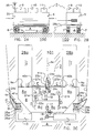
Figure 1 shows a diagrammatic top view of an example of an assembly according to the invention; -
Figures 2A-C show a milking station for an embodiment of an assembly according to the invention, in side view, in end view and in cut-away top view, respectively. -
Figures 3 and 3A show a front view of a self-propelled wire holder for an embodiment of an assembly according to the invention and a detail thereof, respectively, and -
Figures 4A-D show diagrammatic top views of a few possible embodiments of an assembly according to the invention and the use thereof. -
Figure 1 shows a pasture or a wide grazing land, such as aprairie 100, with a fixedreference point 102. Anassembly 1 according to the invention encloses agrazing area 101 for cattle V. For this purpose, theassembly 1 comprises a holder which is implemented as a self-propelledmilking station 2 and, in this example three, self-propelledholders wires holders holders wires - The milking
station 2 inFigures 2A-C comprises a frame 5 with a set ofcaterpillar tracks 7 which run aroundwheels 6 and which are drivable in, for example, directions A by means of a motor (not further shown) which is supported on the frame. Alternatively, the frame 5 may be disposed on one or more rotatable wheel sets with driven wheels, or the like, for an optimum manoeuvrability. The frame 5 comprises aconstruction 20 on which are disposed anenergy supply 9, such as an accumulator or a generator, aconcentrate storage container 10, a water storage container 11 and afuel storage container 12. PV panels (not shown) may also be disposed on theconstruction 20, for energy supply. - Inside the
construction 20 there is provided apassage 8 for cattle, withentrance areas openings doors openings entrance slopes openings swing gates - Inside the
construction 20 there is further provided a control unit 13 provided with (not shown) programming and data input means and a transmitter/receiver 35. The functions in theassembly 1 are controlled by means of the control unit 13. - An
arm 16 of a milkingrobot 15 to be controlled by the control unit 13, which arm is provided with aholder 17 with teat cups, may extend into thepassage 8. Thearm 16 is movable in the directions C, between a storage position and a use position. The robot is centrally positioned, so that it can be used when an animal is standing in the milk stand 8c or in the milk stand 8d. - In order to determine the position for the milk stands 8c,8d, the
construction 20 is further provided with (concentrate) feedtroughs 22a,22b which are supported onarms robots stand duct 18 coming (direction F) from thestorage container 10, andmetering channel 19 which is rotatable (directions H) between two filling positions. Feed metering, movement of the metering channel and the feed troughs are controlled by the control unit 13. For milking and offering feed there may be used presence detectors which detect an animal and its position in theareas - At its outer side the
construction 20 is provided on three sides withboxes wire reels wires 4a-d form one continuous wire, it will suffice to usewire reel 23a or 23b instead of both 23a and 23b. In this example, in addition,spacer arms construction 20 so as to be pivotable (directions B and P) about horizontal and vertical axes.Pivots arms spacer arms wires construction 20. Thearms reels - The self-propelled
wire holder 3a (substantially equal towire holders frame 30 with separatelydrivable wheels 31a,31b and adrive motor 32 for driving them. Themotor 32 may be fed from the milkingstation 2 by implementing one or more of thewires 4a, etcetera as a double conductor, as described in the above-mentioned documentNL 1013349 wires - The self-propelled
wire holders 3a, etcetera may also be provided with PV panels for self-feeding, and/or chargeable accumulators. For remote control from the control unit 13 thewire 4a, etcetera may also be provided with an appropriate conductor, or a transmitter/receiver 33 may be provided for receiving control signals from the control unit 13 for controlling themotor 32 and the drives of thewheels 31a,31 b. - The
frame 30 carries, in this example, awire angle gauge Figure 3A , the angle betweenwire section 4a andwire section 4b can be determined, as described in the aforementioned documentNL 1013349 - The
frame 30 may additionally - or alternatively - be provided with a plate (not further shown) which can be lowered in a sliding manner along a rod which is placed with its lower end against the ground (and which can be put into and out of operation from the frame 30) so as to be supported on the crop, whereafter the position of the plate along the rod is a measure for the height or the condition of the grass (degree to which it is treaded by cattle). The measured values can be transmitted to the control unit 13 via the transmitter 33. - The
frame 30 may additionally - or alternatively - be provided with hygrometers (not further shown) which determine the moisture content of the ground or the crop, the measured values being transmitted to the control unit 13 via the transmitter 33 and thereceiver 35. - The
wires reels 23a,23b. However, one or more self-propelledwire holders wire 4a, etcetera, and with a fixed fastening for the end of the wire in the next side of the quadrangle. Alternatively, a wire holder 3 may be provided with two or more reels, one for each wire. For each reel there will be provided a drive on the wire holder, and, if desired, gauges for the length of wire hauled in or let out. The data thereof can be transmitted to the control unit 13 via the transmitter 33 and thereceiver 35. In these cases an (almost) entirely circumferential wire is not involved. -
Figure 4A shows an assembly which corresponds to a great extent to the arrangement ofFigure 1 . However, in this case thewire 4e is used, which directly connects the milkingstation 2 to thewire holder 3b. As a result, thegrazing area 101 is divided into two sub-grazing-areas passage 8, from the one sub-grazing-area to the other sub-grazing-area, see arrows X1 and X2. - When, for example, it is detected through the aforementioned measurements that the vegetation in the sub-grazing-
areas Figure 4B , which has another position relative toreference point 102. - The same action may be taken if it results from the aforementioned measurements that the moisture content of the vegetation and/or the ground is so high that there is a swampy condition. In order to prevent damage of the grazing area and/or problems for the cattle, the control unit may activate the self-propelled holders, including the milking station, and control them to move the assembly to a dryer, for example higher situated area 103 (
Figure 4B ). The hygrometers detect the arrival at the drier area. The control unit 13 may be programmed beforehand in such a manner that the self-propelled holder (here 3c), which is the first to detect a sufficiently dry terrain, will continue to drive over a certain distance. Alternatively, the control unit 13 may be programmed in such a manner that the displacement is only completely stopped if all the hygrometers (on all the holders) measure a sufficiently low moisture content. - On the basis of the measured data from the wire angle gauges, the wire length gauges and/or the position gauges, the control unit can follow the exact relative and absolute positions of the holders and determine therefrom the shape, size and position of the assembly and of the grazing area which is enclosed thereby.
- This dynamic, interactive management may also take place by means of the arrangement of
Figure 1 . For the arrangements ofFigures 1 and4A , the control unit may also be set by default to displace the grazing area, together with cattle present therein, gradually, continuously or stepwise, at least one or more of thewires 4a-d, in order regularly to make fresh grass land available. The speed of adaptation may be attuned to the number of animals of the cattle (and the grazing behaviour) in the grazing area or the relevant sub-grazing-area. By regular displacement treading of the terrain is prevented. - If the choice is made to have the cattle stay first in the one sub-grazing-
area 101a and to admit them to the other sub-grazing-area 101b only after the former one has been consumed, the control unit may be programmed to activate thewire holder 3a and to control same (arrow K,Figure 4C ) to reduce the sub-grazing-area 101a after it has been detected that the sub-grazing-area 101a has been consumed. The cattle can go, viapassage 8, arrow X3, to the sub-grazing-area 101b which, if desired, can be increased by activation and control ofwire holder 3c (arrow M).Swing gate 40a can in this case be in the opened position, whileswing gate 40b only allows passage to outside viaopening 9b. The count data are supplied to the control unit which, on the basis thereof, is able to determine the desired size of the sub-grazing-area 101 b. - During the passage of the cattle through the
passage 8, it is possible to successively perform a milking on each of the animals while offering them the feed trough 22b and the use of the milking robot 15-17. The milk is stored in themilk storage 14. If desired, water can be supplied in a not shown manner to the animal from the storage container 11. After an animal has been milked, the feed trough is retracted for a while in order to free thepassage 8 for that animal. - It is also possible to let the sub-grazing-
areas Figure 4A ). Upon displacing (arrow X1) the cattle from sub-grazing-area 101 a to sub-grazing-area 101 b, theswing gate 40a will be open and theswing gate 40b will be operative. Upon displacing (arrow X1) the cattle from sub-grazing-area 101 b to sub-grazing-area 101 a, theswing gate 40b will be open and theswing gate 40a will be operative. Depending on the direction of displacement, either thefeed trough 22a or the feed trough 22b is used. - The
assembly 1 may also be set to have the cattle undergo a milking without moving them to the other sub-grazing-area.Figure 4D shows that the cattle in sub-grazing-area 101 b, via anopen swing gate 40b, goes to the passage 8 (arrow X4), in order to be milked there in milk stand 8d, in which case feedtrough 22a is used. Thefeed trough 22a is not retracted after the animal has been milked, so that the animal can leave the milking station only through theopening 9b, to go to the sub-grazing-area 101 b. -
Figure 4D also indicates that the other sub-area, here 101 c, can be used for segregating cattle. For this purpose, slidingdoor 27a has been shifted in front ofopening 9a. As a result, the cattle cannot perceive the presence of thepassage 8. When the cattle has to be moved from sub-area 101 c (which need not be intended as a grazing area, but for example substantially as a separation area) to another place, the control unit may activate thewire holder 3a and control same to reduce the sub-area 101 c while pushing the cattle in the direction ofspacer arm 24a. In order to let the cattle go outside, it is possible to pivot thespacer arm 24a at the inner end aboutpivot 25a (direction P) while pivoting the portion of thearm 24a that is situated outsidepivot 41 a downwards aboutpivot 41 a, so that the end of the arm, and thereby the place wherewire 4a is kept, is kept vertically in place and thebent arm 24a forms a passage for cattle in the direction X5. If desired, thearms - An area which is separated from access to the milking
station 2 may also be achieved by interconnecting thewire holders Figure 1 by means of a wire (not shown) corresponding towires 4a-d. - The above description is given to illustrate the operation of preferred embodiments of the invention and not in order to limit the scope of the invention. On the basis of the above explanation, many variations which fall within the spirit and scope of the present invention will be obvious to the person skilled in the art.
Claims (15)
- Assembly (1) for delimiting a grazing area (101) for cattle, in particular dairy cattle, comprising at least three holders (2,3a,3b,3c) which are spaced apart and which are directly or indirectly interconnected by one or more delimiting elements (4a,4b,4c,4d,4e), such as wires, which are displaceable by the holders, wherein at least two of the holders are self-propelled and at least one of the holders is implemented as a milking station (2).
- Assembly according to claim 1, wherein the milking station (2) is directly connected, by means of a delimiting element (4a,4d,4e), to at least two of the other holders, in particular to at least three of the other holders (3a,3b,3c).
- Assembly according to any one of the preceding claims, wherein the holders (2,3a,3b,3c) with the delimiting elements extending therebetween define at least one entirely separated grazing area, in particular a closed polygon.
- Assembly according to any one of the preceding claims, wherein the holders (2,3a,3b,3c) with the delimiting elements extending therebetween define at least two separated sub-grazing-areas (101a,101b), in particular wherein the milking station (2) forms a passage (8) for the dairy cattle between both sub-grazing-areas (101a,101b), in particular provided with means (40a,40b) for establishing a selected one-way route for the dairy cattle through the passage and/or provided with means (27a,27b; 40a,40b) for closing the entrance to the milking station from one selected sub-grazing-area and with means for selectively operating the closing means.
- Assembly (1) for delimiting a grazing area for dairy cattle, comprising a delimitation which extends around the grazing area and which is formed by a number of delimiting elements (4a,4b,4c,4d,4e), which are successive in the direction of delimitation, and by a number of holders (2,3a,3b,3c), which are spaced apart in the direction of delimitation, for the successive delimiting elements, wherein the holders comprise a number of self-propelled first vehicles (3a,3b,3c) and a milking station (2).
- Assembly according to any one of the preceding claims, wherein the delimiting element (4a,4b,4c,4d,4e) is flexible and at least one of the holders is provided with means for hauling in/letting out a length of delimiting element and/or for tensioning the delimiting element.
- Assembly according to any one of the preceding claims, wherein at least one of the holders is provided with a programmable control unit (13) for mutually attuned activation and, preferably, also control of the self-propelled holders.
- Assembly according to claim 7, provided with means for determining the number of animals of the dairy cattle in a grazing area defined by the holders, wherein the control unit (13) is arranged to activate and control the self-propelled holders in dependence on the determined number.
- Assembly according to claim 21 or 22, provided with means for determining the surface area of the grazing area defined by the holders, which means are operatively connected to the control unit (13), in particular wherein the means for determining the surface area of the grazing area defined by the holders comprise means, provided on one or more of the holders, for measuring the angle between delimiting elements emanating from the relevant holder and/or comprise means, provided on one or more of the holders, for measuring the distance between one or more pairs of holders, and/or comprise means, provided on one or more of the holders, for determining the position of the holder in the horizontal plane.
- Assembly according to claim 7, provided with means for determining a condition of the grazing land in a grazing area defined by the holders, wherein the control unit (13) is arranged to activate and control the self-propelled holders in dependence on the determined condition, wherein the means for determining a condition of the grazing land in a grazing area defined by the holders are in particular arranged to locally measure a value which is indicative of the amount of vegetation and/or to locally measure the height of the terrain and/or to measure the moisture content of the air or the ground.
- Assembly for delimiting a grazing area for cattle, comprising a delimitation which extends around the area and which is formed by a number of delimiting elements (4a,4b,4c,4d,4e), which are successive in the direction of delimitation, and by a number of holders (2,3a,3b,3c), which are spaced apart in the direction of delimitation, for the successive delimiting elements, wherein all the holders are self-propelled.
- Method of pasturing grazing land with dairy cattle, wherein a grazing area is enclosed by means of an assembly according to any one of the preceding claims, and the position of one or more of the self-propelled holders is adapted by activation of said holders.
- Method according to claim 12, wherein the activation of the relevant holders takes place in dependence on a count of the number of animals of the cattle and/or in dependence on a measurement of the condition of the vegetation in the grazing area, in particular wherein the measured condition is the amount of vegetation or the moisture content of the air or the ground.
- Method according to claim 12 or 13, wherein the mutual position of the holders is monitored and the activation of the holders takes place at least on the basis of these data.
- Method according to any one of claims 12-14, wherein all the holders are self-propelled and are all activated for displacement together with the cattle which is enclosed by the assembly.
Applications Claiming Priority (1)
| Application Number | Priority Date | Filing Date | Title |
|---|---|---|---|
| NL1035137A NL1035137C2 (en) | 2008-03-06 | 2008-03-06 | Composition and working method for grazing. |
Publications (2)
| Publication Number | Publication Date |
|---|---|
| EP2098112A1 true EP2098112A1 (en) | 2009-09-09 |
| EP2098112B1 EP2098112B1 (en) | 2011-08-31 |
Family
ID=39745189
Family Applications (1)
| Application Number | Title | Priority Date | Filing Date |
|---|---|---|---|
| EP09075086A Not-in-force EP2098112B1 (en) | 2008-03-06 | 2009-02-27 | Assembly for and method of grazing |
Country Status (7)
| Country | Link |
|---|---|
| US (2) | US20090223454A1 (en) |
| EP (1) | EP2098112B1 (en) |
| AT (1) | ATE522133T1 (en) |
| AU (1) | AU2009200892B2 (en) |
| CA (1) | CA2656865A1 (en) |
| NL (1) | NL1035137C2 (en) |
| NZ (1) | NZ575275A (en) |
Cited By (4)
| Publication number | Priority date | Publication date | Assignee | Title |
|---|---|---|---|---|
| WO2012004110A1 (en) * | 2010-07-08 | 2012-01-12 | Delaval Holding Ab | Method and arrangement for animal management |
| NL2011624C2 (en) * | 2013-10-16 | 2015-04-20 | Romariës Beheer B V | STABLE CLEANING DEVICE. |
| NL2014187A (en) * | 2015-01-26 | 2016-09-27 | Lely Patent Nv | Agricultural management system. |
| EP3647897A3 (en) * | 2018-10-31 | 2020-07-29 | Underground Agriculture Company, LLC | Robotic rotational grazing system |
Families Citing this family (9)
| Publication number | Priority date | Publication date | Assignee | Title |
|---|---|---|---|---|
| NL1032662C2 (en) * | 2006-10-11 | 2008-04-14 | Maasland Nv | System for delimiting an area. |
| NL1035289C2 (en) * | 2008-04-14 | 2009-10-15 | Lely Patent Nv | Provisions and method for separating and sorting livestock. |
| WO2017197494A1 (en) | 2016-04-21 | 2017-11-23 | Badiou Daniel | Mobile animal shelter device |
| CN109960272A (en) * | 2017-12-22 | 2019-07-02 | 翔升(上海)电子技术有限公司 | Grazing method and system based on unmanned plane |
| US11950572B2 (en) * | 2018-10-31 | 2024-04-09 | Dawn Equipment Company, Inc. | Movable electrified fence for rotational grazing |
| US11406082B2 (en) | 2019-08-02 | 2022-08-09 | Douglas Hiller Crain | Pasturing system |
| EP4208015A4 (en) * | 2020-09-04 | 2024-12-04 | Clipex IP Limited | Livestock management sysyem and method |
| RS20201177A1 (en) * | 2020-09-30 | 2022-03-31 | Coming Computer Eng Doo Beograd | Self-propelled system for herd keeping and grazing |
| AR120263A1 (en) * | 2020-10-21 | 2022-02-09 | Antonio Juan Rossi | MODULAR AUTONOMOUS MOBILE FENCE, DELIMITER OF GRAZING AREAS |
Citations (2)
| Publication number | Priority date | Publication date | Assignee | Title |
|---|---|---|---|---|
| US6062165A (en) * | 1996-10-19 | 2000-05-16 | Sieling; Nicolaas Laurisse | Apparatus for and method of farming |
| NL1013349C2 (en) | 1999-10-20 | 2001-04-23 | Lely Res Holding | Device for defining an area as well as a vehicle suitable for use in the device. |
Family Cites Families (7)
| Publication number | Priority date | Publication date | Assignee | Title |
|---|---|---|---|---|
| US4535723A (en) * | 1980-06-09 | 1985-08-20 | Gealy Elizabeth L | Animal handling and processing facility |
| SE513017C2 (en) * | 1998-09-03 | 2000-06-19 | Alfa Laval Agri Ab | A method and apparatus for milking loose dairy animals |
| US6487992B1 (en) * | 1999-11-22 | 2002-12-03 | Robert L. Hollis | Dog behavior monitoring and training apparatus |
| US20050145187A1 (en) * | 2003-12-29 | 2005-07-07 | Gray James D. | Asset management of livestock in an open range using satellite communications |
| NL1029600C2 (en) * | 2005-07-25 | 2007-01-26 | Lely Entpr Ag | Device for delimiting an area. |
| NZ600130A (en) * | 2006-09-05 | 2013-11-29 | Maasland Nv | A milking implement |
| NL1032663C2 (en) * | 2006-10-11 | 2008-04-14 | Maasland Nv | System for delimiting an area. |
-
2008
- 2008-03-06 NL NL1035137A patent/NL1035137C2/en not_active IP Right Cessation
-
2009
- 2009-02-27 EP EP09075086A patent/EP2098112B1/en not_active Not-in-force
- 2009-02-27 AT AT09075086T patent/ATE522133T1/en not_active IP Right Cessation
- 2009-03-03 CA CA002656865A patent/CA2656865A1/en not_active Abandoned
- 2009-03-03 NZ NZ575275A patent/NZ575275A/en not_active IP Right Cessation
- 2009-03-05 AU AU2009200892A patent/AU2009200892B2/en not_active Ceased
- 2009-03-06 US US12/399,040 patent/US20090223454A1/en not_active Abandoned
-
2013
- 2013-06-17 US US13/919,076 patent/US20130269625A1/en not_active Abandoned
Patent Citations (2)
| Publication number | Priority date | Publication date | Assignee | Title |
|---|---|---|---|---|
| US6062165A (en) * | 1996-10-19 | 2000-05-16 | Sieling; Nicolaas Laurisse | Apparatus for and method of farming |
| NL1013349C2 (en) | 1999-10-20 | 2001-04-23 | Lely Res Holding | Device for defining an area as well as a vehicle suitable for use in the device. |
Cited By (4)
| Publication number | Priority date | Publication date | Assignee | Title |
|---|---|---|---|---|
| WO2012004110A1 (en) * | 2010-07-08 | 2012-01-12 | Delaval Holding Ab | Method and arrangement for animal management |
| NL2011624C2 (en) * | 2013-10-16 | 2015-04-20 | Romariës Beheer B V | STABLE CLEANING DEVICE. |
| NL2014187A (en) * | 2015-01-26 | 2016-09-27 | Lely Patent Nv | Agricultural management system. |
| EP3647897A3 (en) * | 2018-10-31 | 2020-07-29 | Underground Agriculture Company, LLC | Robotic rotational grazing system |
Also Published As
| Publication number | Publication date |
|---|---|
| NZ575275A (en) | 2010-09-30 |
| US20090223454A1 (en) | 2009-09-10 |
| ATE522133T1 (en) | 2011-09-15 |
| EP2098112B1 (en) | 2011-08-31 |
| CA2656865A1 (en) | 2009-09-06 |
| NL1035137C2 (en) | 2009-09-08 |
| US20130269625A1 (en) | 2013-10-17 |
| AU2009200892A1 (en) | 2009-09-24 |
| AU2009200892B2 (en) | 2014-06-05 |
Similar Documents
| Publication | Publication Date | Title |
|---|---|---|
| EP2098112B1 (en) | Assembly for and method of grazing | |
| DE3752107T2 (en) | Portable space or container containing a device for automatic milking of animals | |
| US5596945A (en) | Construction for automatically milking animals | |
| DE3650399T3 (en) | Device for milking animals, e.g. Cows. | |
| EP0635203B1 (en) | A construction for automatically milking animals | |
| US10136615B2 (en) | Milking stall | |
| EP0582350B1 (en) | A construction for milking animals | |
| US4194467A (en) | Cow milking system | |
| US6062165A (en) | Apparatus for and method of farming | |
| US3019763A (en) | Mobile milking house and milk room | |
| EP0768027B1 (en) | A Construction for automatically milking animals | |
| EP1491090A2 (en) | An implement for demarcating an area, as well as a vehicle suitable for being used in said implement | |
| DE102004014520A1 (en) | Barn arrangement and stable facility for dairy cattle husbandry | |
| DE60220810T2 (en) | METHOD OF HANDLING ANIMALS AND MELKSTATION | |
| EP0619702B1 (en) | A construction for automatically milking animals | |
| US20210267161A1 (en) | A Pasture Demarcation System for Grazing Animals | |
| EP0622019A1 (en) | A construction for automatically milking animals | |
| DE102013219081B4 (en) | Hanging trolley for cattle shed | |
| JPH1189470A (en) | Feeding equipment | |
| SU1042704A1 (en) | Live stock barn | |
| WO2011034426A1 (en) | Livestock treatment carousel | |
| DE20220764U1 (en) | Mobile milking stall is mounted on wheels and has floor which can be raised and lowered, cows passing through it from entrance to exit and automatic system fitting cluster on teats |
Legal Events
| Date | Code | Title | Description |
|---|---|---|---|
| PUAI | Public reference made under article 153(3) epc to a published international application that has entered the european phase |
Free format text: ORIGINAL CODE: 0009012 |
|
| 17P | Request for examination filed |
Effective date: 20090330 |
|
| AK | Designated contracting states |
Kind code of ref document: A1 Designated state(s): AT BE BG CH CY CZ DE DK EE ES FI FR GB GR HR HU IE IS IT LI LT LU LV MC MK MT NL NO PL PT RO SE SI SK TR |
|
| AX | Request for extension of the european patent |
Extension state: AL BA RS |
|
| 17Q | First examination report despatched |
Effective date: 20091013 |
|
| AKX | Designation fees paid |
Designated state(s): AT BE BG CH CY CZ DE DK EE ES FI FR GB GR HR HU IE IS IT LI LT LU LV MC MK MT NL NO PL PT RO SE SI SK TR |
|
| GRAP | Despatch of communication of intention to grant a patent |
Free format text: ORIGINAL CODE: EPIDOSNIGR1 |
|
| GRAS | Grant fee paid |
Free format text: ORIGINAL CODE: EPIDOSNIGR3 |
|
| GRAA | (expected) grant |
Free format text: ORIGINAL CODE: 0009210 |
|
| AK | Designated contracting states |
Kind code of ref document: B1 Designated state(s): AT BE BG CH CY CZ DE DK EE ES FI FR GB GR HR HU IE IS IT LI LT LU LV MC MK MT NL NO PL PT RO SE SI SK TR |
|
| REG | Reference to a national code |
Ref country code: GB Ref legal event code: FG4D Ref country code: CH Ref legal event code: EP |
|
| REG | Reference to a national code |
Ref country code: NL Ref legal event code: T3 |
|
| REG | Reference to a national code |
Ref country code: IE Ref legal event code: FG4D |
|
| REG | Reference to a national code |
Ref country code: SE Ref legal event code: TRGR |
|
| REG | Reference to a national code |
Ref country code: DE Ref legal event code: R096 Ref document number: 602009002334 Country of ref document: DE Effective date: 20111027 |
|
| LTIE | Lt: invalidation of european patent or patent extension |
Effective date: 20110831 |
|
| PG25 | Lapsed in a contracting state [announced via postgrant information from national office to epo] |
Ref country code: NO Free format text: LAPSE BECAUSE OF FAILURE TO SUBMIT A TRANSLATION OF THE DESCRIPTION OR TO PAY THE FEE WITHIN THE PRESCRIBED TIME-LIMIT Effective date: 20111130 Ref country code: LT Free format text: LAPSE BECAUSE OF FAILURE TO SUBMIT A TRANSLATION OF THE DESCRIPTION OR TO PAY THE FEE WITHIN THE PRESCRIBED TIME-LIMIT Effective date: 20110831 Ref country code: IS Free format text: LAPSE BECAUSE OF FAILURE TO SUBMIT A TRANSLATION OF THE DESCRIPTION OR TO PAY THE FEE WITHIN THE PRESCRIBED TIME-LIMIT Effective date: 20111231 Ref country code: FI Free format text: LAPSE BECAUSE OF FAILURE TO SUBMIT A TRANSLATION OF THE DESCRIPTION OR TO PAY THE FEE WITHIN THE PRESCRIBED TIME-LIMIT Effective date: 20110831 Ref country code: HR Free format text: LAPSE BECAUSE OF FAILURE TO SUBMIT A TRANSLATION OF THE DESCRIPTION OR TO PAY THE FEE WITHIN THE PRESCRIBED TIME-LIMIT Effective date: 20110831 |
|
| REG | Reference to a national code |
Ref country code: AT Ref legal event code: MK05 Ref document number: 522133 Country of ref document: AT Kind code of ref document: T Effective date: 20110831 |
|
| PG25 | Lapsed in a contracting state [announced via postgrant information from national office to epo] |
Ref country code: AT Free format text: LAPSE BECAUSE OF FAILURE TO SUBMIT A TRANSLATION OF THE DESCRIPTION OR TO PAY THE FEE WITHIN THE PRESCRIBED TIME-LIMIT Effective date: 20110831 Ref country code: GR Free format text: LAPSE BECAUSE OF FAILURE TO SUBMIT A TRANSLATION OF THE DESCRIPTION OR TO PAY THE FEE WITHIN THE PRESCRIBED TIME-LIMIT Effective date: 20111201 Ref country code: CY Free format text: LAPSE BECAUSE OF FAILURE TO SUBMIT A TRANSLATION OF THE DESCRIPTION OR TO PAY THE FEE WITHIN THE PRESCRIBED TIME-LIMIT Effective date: 20110831 Ref country code: LV Free format text: LAPSE BECAUSE OF FAILURE TO SUBMIT A TRANSLATION OF THE DESCRIPTION OR TO PAY THE FEE WITHIN THE PRESCRIBED TIME-LIMIT Effective date: 20110831 Ref country code: SI Free format text: LAPSE BECAUSE OF FAILURE TO SUBMIT A TRANSLATION OF THE DESCRIPTION OR TO PAY THE FEE WITHIN THE PRESCRIBED TIME-LIMIT Effective date: 20110831 |
|
| PG25 | Lapsed in a contracting state [announced via postgrant information from national office to epo] |
Ref country code: BE Free format text: LAPSE BECAUSE OF FAILURE TO SUBMIT A TRANSLATION OF THE DESCRIPTION OR TO PAY THE FEE WITHIN THE PRESCRIBED TIME-LIMIT Effective date: 20110831 |
|
| PG25 | Lapsed in a contracting state [announced via postgrant information from national office to epo] |
Ref country code: CZ Free format text: LAPSE BECAUSE OF FAILURE TO SUBMIT A TRANSLATION OF THE DESCRIPTION OR TO PAY THE FEE WITHIN THE PRESCRIBED TIME-LIMIT Effective date: 20110831 Ref country code: SK Free format text: LAPSE BECAUSE OF FAILURE TO SUBMIT A TRANSLATION OF THE DESCRIPTION OR TO PAY THE FEE WITHIN THE PRESCRIBED TIME-LIMIT Effective date: 20110831 |
|
| PG25 | Lapsed in a contracting state [announced via postgrant information from national office to epo] |
Ref country code: PT Free format text: LAPSE BECAUSE OF FAILURE TO SUBMIT A TRANSLATION OF THE DESCRIPTION OR TO PAY THE FEE WITHIN THE PRESCRIBED TIME-LIMIT Effective date: 20120102 Ref country code: PL Free format text: LAPSE BECAUSE OF FAILURE TO SUBMIT A TRANSLATION OF THE DESCRIPTION OR TO PAY THE FEE WITHIN THE PRESCRIBED TIME-LIMIT Effective date: 20110831 Ref country code: IT Free format text: LAPSE BECAUSE OF FAILURE TO SUBMIT A TRANSLATION OF THE DESCRIPTION OR TO PAY THE FEE WITHIN THE PRESCRIBED TIME-LIMIT Effective date: 20110831 Ref country code: EE Free format text: LAPSE BECAUSE OF FAILURE TO SUBMIT A TRANSLATION OF THE DESCRIPTION OR TO PAY THE FEE WITHIN THE PRESCRIBED TIME-LIMIT Effective date: 20110831 Ref country code: RO Free format text: LAPSE BECAUSE OF FAILURE TO SUBMIT A TRANSLATION OF THE DESCRIPTION OR TO PAY THE FEE WITHIN THE PRESCRIBED TIME-LIMIT Effective date: 20110831 |
|
| PG25 | Lapsed in a contracting state [announced via postgrant information from national office to epo] |
Ref country code: DK Free format text: LAPSE BECAUSE OF FAILURE TO SUBMIT A TRANSLATION OF THE DESCRIPTION OR TO PAY THE FEE WITHIN THE PRESCRIBED TIME-LIMIT Effective date: 20110831 |
|
| PLBE | No opposition filed within time limit |
Free format text: ORIGINAL CODE: 0009261 |
|
| STAA | Information on the status of an ep patent application or granted ep patent |
Free format text: STATUS: NO OPPOSITION FILED WITHIN TIME LIMIT |
|
| 26N | No opposition filed |
Effective date: 20120601 |
|
| REG | Reference to a national code |
Ref country code: DE Ref legal event code: R097 Ref document number: 602009002334 Country of ref document: DE Effective date: 20120601 |
|
| PG25 | Lapsed in a contracting state [announced via postgrant information from national office to epo] |
Ref country code: MC Free format text: LAPSE BECAUSE OF NON-PAYMENT OF DUE FEES Effective date: 20120229 |
|
| REG | Reference to a national code |
Ref country code: IE Ref legal event code: MM4A |
|
| PG25 | Lapsed in a contracting state [announced via postgrant information from national office to epo] |
Ref country code: IE Free format text: LAPSE BECAUSE OF NON-PAYMENT OF DUE FEES Effective date: 20120227 |
|
| PG25 | Lapsed in a contracting state [announced via postgrant information from national office to epo] |
Ref country code: MK Free format text: LAPSE BECAUSE OF FAILURE TO SUBMIT A TRANSLATION OF THE DESCRIPTION OR TO PAY THE FEE WITHIN THE PRESCRIBED TIME-LIMIT Effective date: 20110831 |
|
| PG25 | Lapsed in a contracting state [announced via postgrant information from national office to epo] |
Ref country code: ES Free format text: LAPSE BECAUSE OF FAILURE TO SUBMIT A TRANSLATION OF THE DESCRIPTION OR TO PAY THE FEE WITHIN THE PRESCRIBED TIME-LIMIT Effective date: 20111211 |
|
| PG25 | Lapsed in a contracting state [announced via postgrant information from national office to epo] |
Ref country code: BG Free format text: LAPSE BECAUSE OF FAILURE TO SUBMIT A TRANSLATION OF THE DESCRIPTION OR TO PAY THE FEE WITHIN THE PRESCRIBED TIME-LIMIT Effective date: 20111130 |
|
| PG25 | Lapsed in a contracting state [announced via postgrant information from national office to epo] |
Ref country code: MT Free format text: LAPSE BECAUSE OF FAILURE TO SUBMIT A TRANSLATION OF THE DESCRIPTION OR TO PAY THE FEE WITHIN THE PRESCRIBED TIME-LIMIT Effective date: 20110831 |
|
| REG | Reference to a national code |
Ref country code: CH Ref legal event code: PL |
|
| GBPC | Gb: european patent ceased through non-payment of renewal fee |
Effective date: 20130227 |
|
| PG25 | Lapsed in a contracting state [announced via postgrant information from national office to epo] |
Ref country code: CH Free format text: LAPSE BECAUSE OF NON-PAYMENT OF DUE FEES Effective date: 20130228 Ref country code: LI Free format text: LAPSE BECAUSE OF NON-PAYMENT OF DUE FEES Effective date: 20130228 |
|
| PG25 | Lapsed in a contracting state [announced via postgrant information from national office to epo] |
Ref country code: GB Free format text: LAPSE BECAUSE OF NON-PAYMENT OF DUE FEES Effective date: 20130227 |
|
| PG25 | Lapsed in a contracting state [announced via postgrant information from national office to epo] |
Ref country code: TR Free format text: LAPSE BECAUSE OF FAILURE TO SUBMIT A TRANSLATION OF THE DESCRIPTION OR TO PAY THE FEE WITHIN THE PRESCRIBED TIME-LIMIT Effective date: 20110831 |
|
| PG25 | Lapsed in a contracting state [announced via postgrant information from national office to epo] |
Ref country code: LU Free format text: LAPSE BECAUSE OF NON-PAYMENT OF DUE FEES Effective date: 20120227 |
|
| PG25 | Lapsed in a contracting state [announced via postgrant information from national office to epo] |
Ref country code: HU Free format text: LAPSE BECAUSE OF FAILURE TO SUBMIT A TRANSLATION OF THE DESCRIPTION OR TO PAY THE FEE WITHIN THE PRESCRIBED TIME-LIMIT Effective date: 20090227 |
|
| REG | Reference to a national code |
Ref country code: FR Ref legal event code: PLFP Year of fee payment: 8 |
|
| REG | Reference to a national code |
Ref country code: FR Ref legal event code: PLFP Year of fee payment: 9 |
|
| REG | Reference to a national code |
Ref country code: FR Ref legal event code: PLFP Year of fee payment: 10 |
|
| PGFP | Annual fee paid to national office [announced via postgrant information from national office to epo] |
Ref country code: NL Payment date: 20190226 Year of fee payment: 11 |
|
| PGFP | Annual fee paid to national office [announced via postgrant information from national office to epo] |
Ref country code: DE Payment date: 20190227 Year of fee payment: 11 |
|
| PGFP | Annual fee paid to national office [announced via postgrant information from national office to epo] |
Ref country code: FR Payment date: 20190225 Year of fee payment: 11 Ref country code: SE Payment date: 20190227 Year of fee payment: 11 |
|
| REG | Reference to a national code |
Ref country code: DE Ref legal event code: R119 Ref document number: 602009002334 Country of ref document: DE |
|
| REG | Reference to a national code |
Ref country code: SE Ref legal event code: EUG |
|
| REG | Reference to a national code |
Ref country code: NL Ref legal event code: MM Effective date: 20200301 |
|
| PG25 | Lapsed in a contracting state [announced via postgrant information from national office to epo] |
Ref country code: SE Free format text: LAPSE BECAUSE OF NON-PAYMENT OF DUE FEES Effective date: 20200228 |
|
| PG25 | Lapsed in a contracting state [announced via postgrant information from national office to epo] |
Ref country code: NL Free format text: LAPSE BECAUSE OF NON-PAYMENT OF DUE FEES Effective date: 20200301 |
|
| PG25 | Lapsed in a contracting state [announced via postgrant information from national office to epo] |
Ref country code: FR Free format text: LAPSE BECAUSE OF NON-PAYMENT OF DUE FEES Effective date: 20200229 Ref country code: DE Free format text: LAPSE BECAUSE OF NON-PAYMENT OF DUE FEES Effective date: 20200901 |