EP2097819B1 - Demand-driven prioritized data structure - Google Patents
Demand-driven prioritized data structure Download PDFInfo
- Publication number
- EP2097819B1 EP2097819B1 EP07862232.1A EP07862232A EP2097819B1 EP 2097819 B1 EP2097819 B1 EP 2097819B1 EP 07862232 A EP07862232 A EP 07862232A EP 2097819 B1 EP2097819 B1 EP 2097819B1
- Authority
- EP
- European Patent Office
- Prior art keywords
- data
- node
- nodes
- radio
- data unit
- Prior art date
- Legal status (The legal status is an assumption and is not a legal conclusion. Google has not performed a legal analysis and makes no representation as to the accuracy of the status listed.)
- Active
Links
Images



Classifications
-
- H—ELECTRICITY
- H04—ELECTRIC COMMUNICATION TECHNIQUE
- H04W—WIRELESS COMMUNICATION NETWORKS
- H04W40/00—Communication routing or communication path finding
- H04W40/24—Connectivity information management, e.g. connectivity discovery or connectivity update
- H04W40/248—Connectivity information update
-
- H—ELECTRICITY
- H04—ELECTRIC COMMUNICATION TECHNIQUE
- H04L—TRANSMISSION OF DIGITAL INFORMATION, e.g. TELEGRAPHIC COMMUNICATION
- H04L47/00—Traffic control in data switching networks
- H04L47/10—Flow control; Congestion control
- H04L47/24—Traffic characterised by specific attributes, e.g. priority or QoS
- H04L47/2425—Traffic characterised by specific attributes, e.g. priority or QoS for supporting services specification, e.g. SLA
- H04L47/2433—Allocation of priorities to traffic types
-
- H—ELECTRICITY
- H04—ELECTRIC COMMUNICATION TECHNIQUE
- H04W—WIRELESS COMMUNICATION NETWORKS
- H04W28/00—Network traffic management; Network resource management
- H04W28/02—Traffic management, e.g. flow control or congestion control
- H04W28/021—Traffic management, e.g. flow control or congestion control in wireless networks with changing topologies, e.g. ad-hoc networks
-
- H—ELECTRICITY
- H04—ELECTRIC COMMUNICATION TECHNIQUE
- H04W—WIRELESS COMMUNICATION NETWORKS
- H04W28/00—Network traffic management; Network resource management
- H04W28/02—Traffic management, e.g. flow control or congestion control
- H04W28/0231—Traffic management, e.g. flow control or congestion control based on communication conditions
-
- H—ELECTRICITY
- H04—ELECTRIC COMMUNICATION TECHNIQUE
- H04W—WIRELESS COMMUNICATION NETWORKS
- H04W40/00—Communication routing or communication path finding
- H04W40/02—Communication route or path selection, e.g. power-based or shortest path routing
- H04W40/12—Communication route or path selection, e.g. power-based or shortest path routing based on transmission quality or channel quality
-
- H—ELECTRICITY
- H04—ELECTRIC COMMUNICATION TECHNIQUE
- H04W—WIRELESS COMMUNICATION NETWORKS
- H04W40/00—Communication routing or communication path finding
- H04W40/02—Communication route or path selection, e.g. power-based or shortest path routing
- H04W40/20—Communication route or path selection, e.g. power-based or shortest path routing based on geographic position or location
-
- H—ELECTRICITY
- H04—ELECTRIC COMMUNICATION TECHNIQUE
- H04W—WIRELESS COMMUNICATION NETWORKS
- H04W8/00—Network data management
- H04W8/02—Processing of mobility data, e.g. registration information at HLR [Home Location Register] or VLR [Visitor Location Register]; Transfer of mobility data, e.g. between HLR, VLR or external networks
- H04W8/04—Registration at HLR or HSS [Home Subscriber Server]
-
- H—ELECTRICITY
- H04—ELECTRIC COMMUNICATION TECHNIQUE
- H04W—WIRELESS COMMUNICATION NETWORKS
- H04W84/00—Network topologies
- H04W84/18—Self-organising networks, e.g. ad-hoc networks or sensor networks
-
- Y—GENERAL TAGGING OF NEW TECHNOLOGICAL DEVELOPMENTS; GENERAL TAGGING OF CROSS-SECTIONAL TECHNOLOGIES SPANNING OVER SEVERAL SECTIONS OF THE IPC; TECHNICAL SUBJECTS COVERED BY FORMER USPC CROSS-REFERENCE ART COLLECTIONS [XRACs] AND DIGESTS
- Y02—TECHNOLOGIES OR APPLICATIONS FOR MITIGATION OR ADAPTATION AGAINST CLIMATE CHANGE
- Y02D—CLIMATE CHANGE MITIGATION TECHNOLOGIES IN INFORMATION AND COMMUNICATION TECHNOLOGIES [ICT], I.E. INFORMATION AND COMMUNICATION TECHNOLOGIES AIMING AT THE REDUCTION OF THEIR OWN ENERGY USE
- Y02D30/00—Reducing energy consumption in communication networks
- Y02D30/70—Reducing energy consumption in communication networks in wireless communication networks
Definitions
- the present invention relates generally to ad-hoc networking, and more specifically to disseminating data among nodes in a radio environment.
- US 2006/227796 relates to a method and apparatus to facilitate real-time packed scheduling in a wireless communications system.
- the present invention advantageously provides an efficient data structure that allows optimization of the total amount of data received by the whole system.
- the current invention uses knowledge about the state of the nodes, the importance of data units to be disseminated, as well as the wireless environment information, to optimize how data should be prioritized and scheduled.
- the system and method comprises identifying a data unit, assigning a class to the data unit, generally based on who needs that data most, identifying a connectivity type which can describe the topology of the nodes and the transmission rate among the nodes, computing a significance factor based on the connectivity type and the class, mapping the significance factor to a priority factor, and scheduling output of the data unit based on the priority factor.
- the class is assigned based on which nodes possess copies of the data unit at a given time.
- computing a significance factor is done using an algorithm based on how many nodes will receive data, and the importance to a particular node to obtain the data.
- the present invention advantageously provides a system and method for optimizing the efficiency of data sharing among a set of radio nodes in a harsh radio environment.
- the solution enables the efficient dissemination of data that was not successfully received by all nodes during a first broadcast of the data.
- the system and method consider the dynamic situation including the data received status of each node and the connectivity of all the nodes, and assign priority to each data unit so that the overall performance is optimized.
- a harsh radio environment in which connectivity is intermittent such as the Adaptive Cognition Enhanced Radio Teams (ACERT) environment
- ACERT Adaptive Cognition Enhanced Radio Teams
- Four radio nodes moving around will try to send data to all the radio nodes or team members. The goal is for each node to send all the locally generated data to all the team members in the shortest time.
- Likely scenarios for the ACERT environment include those in which the amount of data awaiting to be disseminated and the amount of data that have been received can be significantly different for each node, depending on the connectivity of the nodes and the capacity of the channels. Optimization of data dissemination with respect to a broadcast (or multicast) environment is called “non-flat" broadcasting.
- the ACERT environment adds further complexity since the channel capacity is changing.
- the present invention illustrates how the data should be organized, prioritized, and propagated to better match the characteristics of the dynamic channel and the multicast application, optimizing data dissemination.
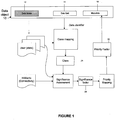
- Figure 1 shows a schematic diagram for the computing of priority information in an embodiment of the invention
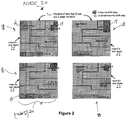
- Figure 2 is a snapshot of four application maps in a node.
- Each data object 10 has 3 parts: data state 12, data unit 14, and metadata 16.
- Data state 12 is the property of the data that indicates whether the data unit 14 exists in the node 20, shown in Figure 2 .
- a user digest 22, shown in Figure 2 and described in detail below, is created based on the data state 12.
- the data unit 14 carries the data type or content of the data such as the environment signal to noise ratio (SNR) measurement, radio link SNR, time, and location information, such as location determined via global positioning satellite (GPS), or other data.
- Metadata 16 is the priority data and may carry other information such as instructions for how the data object is handled.
- the ACERT application multicasts data of different data types. Different types of data may be placed in separate packets (packetized separately) or bundled together. These data packets are ACERT data units 14.
- the total data is known as the application data map or application map 18, shown in Figure 2 .
- a data unit 14 may represent any of the above data types. This is called an application data map 18 since when a piece of data unit 14 is generated, it is usually associated with a grid location, such as a SNR measurement, or a piece of time and position data.
- a data unit 14 does not need to be associated with a particular location. Instead, for example, a data unit 14 can be associated with time, or just associated with a sequence number.
- Figure 2 shows a snapshot of four application maps 18 in node D 20, in which the shaded cells or little squares represent data units 14 of either locally generated data or received data.
- This snapshot can be used to measure the benefit to the ACERT system with respect to broadcasting a piece of data unit 14.
- the application map 18 of each node 20 can be represented as a user-level digest, or user digest 22, that is, a table with entries of 0's and 1°s for a node 20.
- a 0 indicates the absence of a particular data unit 14 while a 1 indicates its presence.
- the user digest 22 is broadcast to all the other nodes 20 regularly, e.g. once every ten seconds.
- the optimum value of frequency of user digest broadcast is a systems parameter and will depend on the overall resource of the system.
- SWF Significance Weighting Factor
- DDPDS Demand-Driven Priority Data Structure
- class 0010 24 refers to the data that only node 3 20 possesses.
- node 3 20 broadcasts this data unit 14
- three other nodes 20 will receive, and benefit from, the data, thereby increasing the total benefit count of the ACERT system by three units of data.
- nodes 1, 3, and 4 all have the data unit 14. If node 3 20 broadcasts this data unit 14, if the broadcast is successful, only node 2 20 will benefit from it, raising the total benefit count by one unit.
- sending data from class 1011 24 is expected to provide less value from the perspective of ACERT's overall goal.
- ACERT nodes 20 connectivity among ACERT nodes 20 can be described by a matrix H, which is an n x n matrix where the i-jth element indicates the minimum number of radio hops between node i and node j .
- H connectivity among ACERT nodes 20
- the radio power of node i and j can reach each other, they are 1-hop connected.
- node 1 and 3 are 1-hop connected and node 3 and 2 are also 1-hop connected, but node 1 and 2 are not within each other's radio range, node 1 and 2 are 2-hop connected, with a corresponding entry of 2 in the H matrix (first row, second column).
- node x and node y are n -hop connected if the shortest path between them contains n radio links.
- G i is defined with respect to a broadcasting radio node 20.
- a group G i consists of the broadcasting node i and all the nodes that are 1-hop connected to i .
- the different types of neighboring groups with respect to different radio nodes 20 of Figure 3 are shown in Figure 4 .
- FIG 4 As illustrated in Figure 4 , for each group, there are eight types of connectivity in the four-node ACERT environment.
- the circled connectivity type 26 of each group corresponds to the radio hop topology of Figure 3 .
- the connectivity topology will impact the significance of the Delivery Data class 24 with respect to the overall ACERT goal, and will be described in more detail below.
- Table 2 The impact of connectivity on the benefit of broadcasting a particular class 24 of data is shown in Table 2, which has columns of the different group types, and rows of the classes 24, and can portray placing the classes 24 against the neighboring group types.
- Table 2 numerical values are placed in the relevant entries of the table, each value or entry is total number of data units 14 received in the ACERT system if the particular class 24 of data unit 14 is broadcasted. This entry can be considered as a first level priority assignment, where a bigger number suggests higher priority.
- a node ID e.g. - (B)
- node B the node inside the parenthesis
- the reason for another node sending the data is that when there is more than one node possessing the data, only one node should send the data, to avoid duplication. Therefore, an arbitration process can be executed among the nodes 20 so that only one node 20 sends the data unit 14. The arbitration process depends on the proximity and channel conditions among the peers, with details of the algorithm presented below.
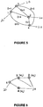
- a distance metric as shown in Figure 5 can provide the criteria for choosing a certain node in Table 2. In this embodiment, the shorter distance is selected.
- DDPDS Table 3 DDPDS Table (1-hop nodes) Class ABCD Node A's Neighborhood Group Types A-BCD A-BC A-BD A-CD A-B A-C A-D A- 0000 - - - - - - - - 0001 - - - - - - - - - 0010 - - - - - - - - - 0011 - - - - - - - - 0100 - - - - - - - 0101 - - - - - - - - 0110 - - - - - - - - - 0111 - - - - - - - - - 1000 w 2 +w 3 + w 4 w 2 +w 3 w 2 +w 4 w 3 +w 4 w 2 w 3 +w 4 w 2 w 3 w 4 - w
- the SF 28 can then be mapped into Priority classes either via pre-defined mapping, or ranked based mapping.
- the SF 28 is augmented to include assigning weights to second hop nodes. This is illustrated in Figure 6 .
- node 1 20 is directly connected to node 3 20 and node 4 20, and is 2-hop connected to node 2 20 via node 3 20.
- node 2 20 is data-hungry, that is, lacking much data, it can be worthwhile to send a data unit 14 to node 3 20 and request the data unit 14 be forwarded to node 2 20. This occurs when w 2 is large.
- node 1 20 needs to mark the data so that node 3 20 can immediately send the data unit 14 to node 2 20 with the highest priority.
- the new SF 28 for 2-hop networks is given by: ⁇ y ⁇ x 1 ⁇ ⁇ y w y p xy + ⁇ z ⁇ x z ⁇ y t 2 w z p yz
- t 2 is a coefficient assigned for 2-hop nodes and defined as ⁇ (1- ⁇ y ).
- the initial value of ⁇ can be assigned between 0.5-1. Details of ⁇ are not addressed herein.
- the priority computation operates as follows.
- a data unit 14 is created and assigned a unique identifier, such as a file name.
- User digest 22 is obtained periodically, which is used to assign class mapping to the data unit 14 according to Table 1.
- the H -matrix identifies the connectivity type 26, which corresponds to the column of Table 3, which is used to compute the SF 28 using Eq. 3.4.
- SF 28 is then mapped to a priority factor 30, e.g. 1 to q, according to some predefined mapping or a straight ranking arrangement.
- FIG. 7 is a flow chart of an embodiment of the invention in accordance with Figures 1 and 2 .
- a data unit 14 is created at a node 20 and assigned a unique identifier, such as a file name, in step S1.
- a class 24 is assigned to the data unit 14 in step 2, based on an application map 18.
- the connectivity type 26 is identified in accordance with an H -matrix, described above, which corresponds to the column of Table 3 or Table 4.
- the SF 28 is computed in step S4.
- SF 28 is then mapped to a priority factor 30 in step S5, according to some predefined mapping or a straight ranking arrangement.
- a scheduler (not shown) is used to schedule the output of the data unit in the FIFO buffer in step S6. Scheduler algorithms such as priority queuing, and/or weighted priority queue, may be used.
- arbitration process When more than one node 20 has the same class 24 of data, it is desirable to have an arbitration process so that only one node 20 sends the data or data unit 14.
- This section provides an algorithm that can be used for this arbitration. Note that the arbitration process is run independently on each node 20 based on the node's local view of network connectivity. The nodes share data about the communication environment continuously, but for arbitration, they do not have explicit communication; they just use the information that they have already collected.
- the arbitration algorithm is as follows.
- the ACERT environment can be defined within a grid of 100m by 100m, which is divided into 1m 2 "cells".
- four ACERT nodes will be moving in designated paths at a pace of ⁇ 1.4m/s for a thirty minute period called a run. During this period, each node will traverse about 25% of the grid, performing a number of measurements including locating itself, measuring an environmental SNR value called SNR map, and estimating the capability to communicate to all the other nodes of the team. All the measurement data need to be disseminated to all the other nodes of the team within the run. At the end of the run, the measured data will be evaluated on its integrity against some predefined metrics.
- communication radio link performance information can be kept, all other measurements including the SNR map, are to be discarded.
- a second run of another thirty minutes will be performed. The purpose of the second run is to test how well the cognitive algorithm performs. The same set of parameters will be measured in the second run, except that the metrics are more stringent.
- a fundamental characteristic of the ACERT application is that data need to be disseminated from each node to all the other nodes during the thirty minute run. Since the evaluation metric evaluates the amount of data disseminated to all the nodes during the run, there is no delay requirement on each message or packet during the communications among ACERT nodes. Each node will be generating new data as it traverses the grid.
- ACERT Cognitive Adaptive Radio Team
- CART Cognitive Adaptive Radio Team
- a demonstration of the quantitative advantage of using the DDPDS follows. This example focuses on the data storage and transmission at one of the ACERT nodes, that is, node A.
- the classes 1000, 1001,...1110, classes 8 to 14 of Table 1 above can be modeled as FIFO buffers.
- the FIFO buffers at each node are each expected to have data waiting to be sent out.
- the total units of benefit can be computed by counting the weighted sum of the number of zeros in the selected, shaded classes, the weight being the number of data units selected for that particular class, which comes out to be thirty units. This is over fifty percent better than Strategy I.
- each node is moving at a rate of about 1.4m/s.
- the 802.11 radio link used for phase 1 has a range of several tens of meters.
- the connectivity topology is expected to change in the order of seconds or tens of seconds. This is an important systems parameter, which is directly related to the systems requirement for the rate of priority update.
Landscapes
- Engineering & Computer Science (AREA)
- Computer Networks & Wireless Communication (AREA)
- Signal Processing (AREA)
- Databases & Information Systems (AREA)
- Mobile Radio Communication Systems (AREA)
- Data Exchanges In Wide-Area Networks (AREA)
Description
- The present invention relates generally to ad-hoc networking, and more specifically to disseminating data among nodes in a radio environment.
- In a harsh radio environment, where deep fading and noisy conditions are commonplace, the availability of a link between any two nodes is uncertain. One can expect that loss of connectivity may last for an extended period of time. Yet, a team of ad-hoc mobile nodes moving around the harsh environment need to send data to all the other radio nodes in the environment. Due to the uncertainty of the availability of links, a large percent of the sent data do not arrive at all the other nodes when first transmitted. Accordingly, these data must subsequently be sent again.
- Existing methods, such as epidemic algorithms and gossip algorithms, are traditionally used to retransmit data that had not initially been received at all of the nodes. In these approaches, each node randomly picks a neighbor, finds out what data is missing from that neighbor and transmits the missing data. However, retransmissions using these methods are inefficient because, among other things, redundant data is transmitted.
- In "Epidemic Algorithms for Replicated Database Management" in ACM Symposium on Principles of Distributed Computing, 1987, Demers et al. describe anti-entropy and rumor mongering as examples of epidemic processes. In anti-entropy, each site regularly chooses another site at random and exchanges information with it. This is a reliable technique for propagating data, but is quite cumbersome, because the exchanges can involve redundant or repetitious data transmission. In rumor mongering, a site receives an update, or "hot rumor" which it tries to share with other sites by asking one of those other sites whether it has the hot rumor. If the hot rumor is shared with one site, another site can be asked. Rumor mongering again can involve redundant transmission of data, and also is not as reliable as anti-entropy because there is a chance that an update will not reach all sites.
- R. Chandra, et al., in "Anonymous Gossip: Improving Multicast Reliability in Mobile Ad-Hoc Networks," International Conference on Distributed Computing Systems, 2001, describe implementing periodic anonymous gossip in the background to ensure that most of the reachable members of a network receive packets which have been multicast to the group. In a round of gossip, an originator node randomly selects another node in its group and sends the selected node information about the originator's messages. If the selected node does not already have the originator's messages, the two nodes can exchange messages. However, transmission of duplicate or redundant data can occur.
-
US 2006/227796 relates to a method and apparatus to facilitate real-time packed scheduling in a wireless communications system. - Among the problems of the aforementioned approaches is the use of a point-to-point or node-to-node solution as well as the lack of information regarding what the rest of the nodes are doing. As a result, these approaches are not optimized for the radio environment, which is inherently a broadcast medium, transmitting to multiple nodes simultaneously.
- "Evaluation of Packet Scheduling Algorithms in Mobile Ad-Hoc Networks", by Byung-Gon Chun et al., Mobile Computing and Communications Review, ACM, New York, NY, vol. 6, no. 3, 1 July 2002, pages 36-49, XP002472934, discloses queuing dynamics at nodes and evaluation of network performance in an ad-hoc mobile network.
- In a harsh wireless environment in which ad-hoc wireless nodes are configured in a mesh network, a common application is to have each node broadcast or multicast data to other nodes. Because wireless ad-hoc networks are inherently unreliable, transmitted data very often do not reach intended destination and therefore retransmission of this data, very often multiple retransmissions, is required. In the absence of careful scheduling and planning, this retransmission causes significant inefficiency, from the perspective of the entire network, due to redundancy and lack of knowledge of urgency of the data.
- In one aspect of the invention, there is provided a method according to
claim 1. In another aspect of the invention, there is provided a system according to claim 8. - The present invention advantageously provides an efficient data structure that allows optimization of the total amount of data received by the whole system. The current invention uses knowledge about the state of the nodes, the importance of data units to be disseminated, as well as the wireless environment information, to optimize how data should be prioritized and scheduled. Specifically, the system and method comprises identifying a data unit, assigning a class to the data unit, generally based on who needs that data most, identifying a connectivity type which can describe the topology of the nodes and the transmission rate among the nodes, computing a significance factor based on the connectivity type and the class, mapping the significance factor to a priority factor, and scheduling output of the data unit based on the priority factor. In one embodiment, the class is assigned based on which nodes possess copies of the data unit at a given time. In one embodiment, computing a significance factor is done using an algorithm based on how many nodes will receive data, and the importance to a particular node to obtain the data.
- The invention is further described in the detailed description that follows, by reference to the noted drawings by way of non-limiting illustrative embodiments of the invention, in which like reference numerals represent similar parts throughout the drawings. As should be understood, however, the invention is not limited to the precise arrangements and instrumentalities shown. In the drawings:
-
Figure 1 is a schematic diagram of the prioritizing portion of the invention; -
Figure 2 is a snapshot of four application maps in a node; -
Figure 3 illustrates a Connectivity Matrix and Radio Hops; -
Figure 4 illustrates Types of Neighborhood Groups; -
Figure 5 illustrates a Distance Metric for Arbitration; -
Figure 6 illustrates Assignment of Weights to 2-hop Nodes; -
Figure 7 is a flow chart of an embodiment of the invention; -
Figure 8 is a benefit count in strategy I; and -
Figure 9 is a benefit count in strategy II. - The present invention advantageously provides a system and method for optimizing the efficiency of data sharing among a set of radio nodes in a harsh radio environment. The solution enables the efficient dissemination of data that was not successfully received by all nodes during a first broadcast of the data. The system and method consider the dynamic situation including the data received status of each node and the connectivity of all the nodes, and assign priority to each data unit so that the overall performance is optimized.
- A harsh radio environment in which connectivity is intermittent, such as the Adaptive Cognition Enhanced Radio Teams (ACERT) environment, provides an example of the environment where the present invention can be applied. Four radio nodes moving around will try to send data to all the radio nodes or team members. The goal is for each node to send all the locally generated data to all the team members in the shortest time. Likely scenarios for the ACERT environment include those in which the amount of data awaiting to be disseminated and the amount of data that have been received can be significantly different for each node, depending on the connectivity of the nodes and the capacity of the channels. Optimization of data dissemination with respect to a broadcast (or multicast) environment is called "non-flat" broadcasting. The ACERT environment adds further complexity since the channel capacity is changing. This unevenness in data source, data sink, and channel capacity suggests that a prioritized data structure and mechanism can drastically improve overall performance. The present invention illustrates how the data should be organized, prioritized, and propagated to better match the characteristics of the dynamic channel and the multicast application, optimizing data dissemination.
-
Figure 1 shows a schematic diagram for the computing of priority information in an embodiment of the invention, andFigure 2 is a snapshot of four application maps in a node. Eachdata object 10 has 3 parts:data state 12,data unit 14, andmetadata 16.Data state 12 is the property of the data that indicates whether thedata unit 14 exists in thenode 20, shown inFigure 2 . A user digest 22, shown inFigure 2 and described in detail below, is created based on thedata state 12. Thedata unit 14 carries the data type or content of the data such as the environment signal to noise ratio (SNR) measurement, radio link SNR, time, and location information, such as location determined via global positioning satellite (GPS), or other data.Metadata 16 is the priority data and may carry other information such as instructions for how the data object is handled. - The ACERT application multicasts data of different data types. Different types of data may be placed in separate packets (packetized separately) or bundled together. These data packets are
ACERT data units 14. The total data is known as the application data map orapplication map 18, shown inFigure 2 . Adata unit 14 may represent any of the above data types. This is called anapplication data map 18 since when a piece ofdata unit 14 is generated, it is usually associated with a grid location, such as a SNR measurement, or a piece of time and position data. In general, adata unit 14 does not need to be associated with a particular location. Instead, for example, adata unit 14 can be associated with time, or just associated with a sequence number. - As discussed above,
Figure 2 shows a snapshot of fourapplication maps 18 innode D 20, in which the shaded cells or little squares representdata units 14 of either locally generated data or received data. This snapshot can be used to measure the benefit to the ACERT system with respect to broadcasting a piece ofdata unit 14. Theapplication map 18 of eachnode 20 can be represented as a user-level digest, or user digest 22, that is, a table with entries of 0's and 1°s for anode 20. A 0 indicates the absence of aparticular data unit 14 while a 1 indicates its presence. The user digest 22 is broadcast to all theother nodes 20 regularly, e.g. once every ten seconds. The optimum value of frequency of user digest broadcast is a systems parameter and will depend on the overall resource of the system. At eachnode 20, all of the user digests 22 from all of the nodes are compared to create an entity called Significance Weighting Factor (SWF), wy, defined as follows:
wy - A measure of the importance of a data unit that node y does not have, given by,
- where b is a fixed bias of 0.5.
- fy = fraction of y's received data divided by the total acquired data (excluding data generated by y). As an example, the fraction of received data by node C, fC is given by:

- As discussed above, a characteristic of the ACERT environment is that the demand or significance of a unit of data varies according to data types such as time, situation, radio conditions, and the aggregate status of all of the data delivery throughout the ACERT run. To best fit this demand structure, an inventive prioritized data structure called Demand-Driven Priority Data Structure (DDPDS) is provided. This structure is based on a classification of all the
data units 14 at an ACERT node according to which set of nodes of the ACERT team possess that unit of data during a certain time interval. The class is called Data Delivery Class, or simplyclass 24. The total number ofclasses 24 is given by the combination of all the set ofnodes 20 having that unit ofdata 14. Table 1 illustrates the basic structure of theclass 24 for the 4-node ACERT scenario. - Organizing the data in the
classes 24 of DDPDS explicitly differentiates the level of demand for eachdata unit 14. As an example, class 0010 24 refers to the data that onlynode 3 20 possesses. Whennode 3 20 broadcasts thisdata unit 14, if the broadcast is successful, threeother nodes 20 will receive, and benefit from, the data, thereby increasing the total benefit count of the ACERT system by three units of data. As a comparison, for class 1011 24,nodes data unit 14. Ifnode 3 20 broadcasts thisdata unit 14, if the broadcast is successful,only node 2 20 will benefit from it, raising the total benefit count by one unit. Compared to the class 0010 24, sending data from class 1011 24 is expected to provide less value from the perspective of ACERT's overall goal.Table 1 Data Delivery Class Class (δ1δ2δ3δ4) Data possessed by node 1Data possessed by node 2Data possessed by node 3Data possessed by node 40000 0 0 0 0 0001 0 0 0 1 0010 0 0 1 0 0011 0 0 1 1 0100 0 1 0 0 0101 0 1 0 1 0110 0 1 1 0 0111 0 1 1 1 1000 1 0 0 0 1001 1 0 0 1 1010 1 0 1 0 1011 1 0 1 1 1100 1 1 0 0 1101 1 1 0 1 1110 1 1 1 0 1111 1 1 1 1 - The benefit of broadcasting a
particular data unit 14 will also depend on the current communications channels among thenodes 20. In general, connectivity amongACERT nodes 20 can be described by a matrix H, which is an n x n matrix where the i-jth element indicates the minimum number of radio hops between node i and node j. As illustrated inFigure 3 , if the radio power of node i and j can reach each other, they are 1-hop connected. Ifnode node node node - To incorporate the connectivity type or
state 26 in the context of DDPDS, the concept of a neighborhood group, Gi is defined with respect to abroadcasting radio node 20. A group Gi consists of the broadcasting node i and all the nodes that are 1-hop connected to i. The different types of neighboring groups with respect todifferent radio nodes 20 ofFigure 3 are shown inFigure 4 . As illustrated inFigure 4 , for each group, there are eight types of connectivity in the four-node ACERT environment. The circledconnectivity type 26 of each group corresponds to the radio hop topology ofFigure 3 . - The connectivity topology will impact the significance of the
Delivery Data class 24 with respect to the overall ACERT goal, and will be described in more detail below. - The impact of connectivity on the benefit of broadcasting a
particular class 24 of data is shown in Table 2, which has columns of the different group types, and rows of theclasses 24, and can portray placing theclasses 24 against the neighboring group types. In Table 2, numerical values are placed in the relevant entries of the table, each value or entry is total number ofdata units 14 received in the ACERT system if theparticular class 24 ofdata unit 14 is broadcasted. This entry can be considered as a first level priority assignment, where a bigger number suggests higher priority. - In Table 2, there are certain entries where a node ID, e.g. - (B), is entered. This indicates that instead of node A sending the data, it is suggested that the node inside the parenthesis (node B) will send the data. The reason for another node sending the data is that when there is more than one node possessing the data, only one node should send the data, to avoid duplication. Therefore, an arbitration process can be executed among the
nodes 20 so that only onenode 20 sends thedata unit 14. The arbitration process depends on the proximity and channel conditions among the peers, with details of the algorithm presented below. In one embodiment, a distance metric as shown inFigure 5 can provide the criteria for choosing a certain node in Table 2. In this embodiment, the shorter distance is selected.Table 2 Priority Consideration Class ABCD Node A's Neighborhood Group Types A-BCD A-BC A-BD A-CD A-B A-C A-D A- 0000 - - - - - - - - 0001 - - - - - - - - 0010 - - - - - - - - 0011 - - - - - - - - 0100 - - - - - - - - 0101 - - - - - - - - 0110 - - - - - - - - 0111 - - - - - - - - 1000 3 2 2 2 1 1 1 - 1001 2 2 1 1 1 1 - - 1010 2 -(C) 2 -(C) 1 - 1 - 1011 -(D) -(C) 1 - 1 - - - 1100 -(B) 1 -(B) 2 - 1 1 - 1101 1 1 - 1 - 1 - - 1110 -(B) - -(B) 1 - - 1 - 1111 - - - - - - - - - The effect of connectivity and arbitration on assigning values for the
classes 24 of data in DDPDS has been explored. In addition, the effect of the SWF, that is, a measure of the significance of a piece of data with respect to two nodes, e.g. Eq. 3.1, can be included in DDPDS by replacing the entries of DDPDS Table 2 by a Significance Factor (SF) 28, according to the following formula:
-
Class 24 is denoted as binary (δ1 δ2 δ3 δ4), e.g. 0010 isclass 2. δy is 0 if node y does not have the data, and 1 if node y has the data. Thus, class 2 (0010) indicates thatnode 3 has the data whilenodes - wy is a measure of the importance of a
data unit 14, which node x has, but node y does not have (see Eq. 3.1 above); and - p xy is the probability of successful communications between node x and y.
- With this formula, and assuming p xy is 1, we obtain DDPDS Table 3.
Table 3 DDPDS Table (1-hop nodes) Class ABCD Node A's Neighborhood Group Types A-BCD A-BC A-BD A-CD A-B A-C A-D A- 0000 - - - - - - - - 0001 - - - - - - - - 0010 - - - - - - - - 0011 - - - - - - - - 0100 - - - - - - - - 0101 - - - - - - - - 0110 - - - - - - - - 0111 - - - - - - - - 1000 w2+w3+ w4 w2+w3 w2+w4 w3+w4 w2 w3 w4 - 1001 w2+w3 w2+w3 w2 w3 w2 w3 - - 1010 w2+w4 -(C) w2+w4 -(C) w2 - w4 - 1011 -(D) -(C) w2 - w2 - - - 1100 -(B) w3 -(B) w3+w4 - w3 w4 - 1101 w3 w3 - w3 w3 - - 1110 -(B) - -(B) w4 - - w4 - 1111 - - - - - - - - - The
SF 28 can then be mapped into Priority classes either via pre-defined mapping, or ranked based mapping. - Thus, how to assign significance to the
classes 24 taking into account the connectivity topology is described. Nodes that are more than 1-hop away have not been considered, or a weight of zero is assumed to be assigned to the nodes that are 2-hop or more away. This is because the initial focus is on the direct data transfer path, and does not consider indirect transfer such as A→B→C. However, in some very harsh radio environments, certain nodes may not be in each other's range for a long time period. In such situations, it is desirable to take advantage of the indirect path. - To enable the indirect path, the
SF 28 is augmented to include assigning weights to second hop nodes. This is illustrated inFigure 6 . In this scenario,node 1 20 is directly connected tonode 3 20 andnode 4 20, and is 2-hop connected tonode 2 20 vianode 3 20. Whennode 2 20 is data-hungry, that is, lacking much data, it can be worthwhile to send adata unit 14 tonode 3 20 and request thedata unit 14 be forwarded tonode 2 20. This occurs when w2 is large. To implement second hop nodes,node 1 20, for example, needs to mark the data so thatnode 3 20 can immediately send thedata unit 14 tonode 2 20 with the highest priority. Thenew SF 28 for 2-hop networks is given by:
- Where t2 is a coefficient assigned for 2-hop nodes and defined as α(1-δy). The initial value of α can be assigned between 0.5-1. Details of α are not addressed herein.
- An example of comparing 1-hop and 2-hop priority assignment for the topology of
Figure 6 is as follows (assume w2 = w3 > W4, α is 0.5 and w4 > 0.5 w2). In Table 4, mapping of theSF 28 intopriority factor 30 is based on a straight ranking arrangement to illustrate the impact of 2-hop connections.Table 4 Comparison of 1-hop and 2-hop priority assignment Class 1234 1-hop 1-34 2-hop 1-3...2 1-4 1-hop Priority 2-hop Priority 1000 w3+w4 w3+ 0.5w2+ w 41 1 1001 w3 w3+ 0.5 W 22 3 1010 -(C) -(C) - - 1011 - - - - 1100 w3+w4 w3+ w 41 2 1101 w3 w3 2 4 1110 w4 w4 3 5 1111 - - - - - The priority computation operates as follows. A
data unit 14 is created and assigned a unique identifier, such as a file name. User digest 22 is obtained periodically, which is used to assign class mapping to thedata unit 14 according to Table 1. The H-matrix identifies theconnectivity type 26, which corresponds to the column of Table 3, which is used to compute theSF 28 using Eq. 3.4.SF 28 is then mapped to apriority factor 30, e.g. 1 to q, according to some predefined mapping or a straight ranking arrangement. -
Figure 7 is a flow chart of an embodiment of the invention in accordance withFigures 1 and2 . Adata unit 14 is created at anode 20 and assigned a unique identifier, such as a file name, in step S1. Aclass 24 is assigned to thedata unit 14 instep 2, based on anapplication map 18. In step S3, theconnectivity type 26 is identified in accordance with an H-matrix, described above, which corresponds to the column of Table 3 or Table 4. Based on theconnectivity type 26 and theclass 24, theSF 28 is computed in step S4.SF 28 is then mapped to apriority factor 30 in step S5, according to some predefined mapping or a straight ranking arrangement. Once the priority mapping is created, a scheduler (not shown) is used to schedule the output of the data unit in the FIFO buffer in step S6. Scheduler algorithms such as priority queuing, and/or weighted priority queue, may be used. - When more than one
node 20 has thesame class 24 of data, it is desirable to have an arbitration process so that only onenode 20 sends the data ordata unit 14. This section provides an algorithm that can be used for this arbitration. Note that the arbitration process is run independently on eachnode 20 based on the node's local view of network connectivity. The nodes share data about the communication environment continuously, but for arbitration, they do not have explicit communication; they just use the information that they have already collected. The arbitration algorithm is as follows. - 1. If two or
more nodes 20 havedata unit 14, compare the number of nodes that are 1-hop connected from these nodes. The node with the larger number of 1-hop connected nodes wins. This rule can be extended to n hops. - 2. If
rule 1 does not resolve - that is the nodes have the same number of 1-hop connected nodes (or up to n-hop) - compute the total of the distance of all the 1-hop connected nodes; the one with shorter distance wins. - 3. If
rule 2 does not resolve, use the order of node ID so that the smallest or lowest ID wins. - It should be noted that these rules should resolve most of cases. However, in certain scenarios, the rule may become undetermined. The problem is that one node may decide one way, while the other may arrive at a different conclusion, potentially due to synchronization of data or error conditions. However, these cases are rare, and even if it happens, the performance penalty for a non-optimal decision is minor.
- The ACERT environment can be defined within a grid of 100m by 100m, which is divided into 1m2 "cells". In this ACERT example, four ACERT nodes will be moving in designated paths at a pace of ∼1.4m/s for a thirty minute period called a run. During this period, each node will traverse about 25% of the grid, performing a number of measurements including locating itself, measuring an environmental SNR value called SNR map, and estimating the capability to communicate to all the other nodes of the team. All the measurement data need to be disseminated to all the other nodes of the team within the run. At the end of the run, the measured data will be evaluated on its integrity against some predefined metrics. After the first run, communication radio link performance information can be kept, all other measurements including the SNR map, are to be discarded. A second run of another thirty minutes will be performed. The purpose of the second run is to test how well the cognitive algorithm performs. The same set of parameters will be measured in the second run, except that the metrics are more stringent.
- A fundamental characteristic of the ACERT application is that data need to be disseminated from each node to all the other nodes during the thirty minute run. Since the evaluation metric evaluates the amount of data disseminated to all the nodes during the run, there is no delay requirement on each message or packet during the communications among ACERT nodes. Each node will be generating new data as it traverses the grid.
- The implementation of ACERT is called Cognitive Adaptive Radio Team (CART). The CART physical environment is characterized by the following properties:
- An inherent wireless broadcast medium. Unicast and multicast are supported in the same shared medium. Initial implementation is based on 802.11b, therefore, unicast packets are acknowledged while broadcast packets are unacknowledged.
- Precise location of each node is acquired via GPS and an anchored node system. Location information is distributed among ACERT nodes.
- Each node is capable of learning about its surrounding radio environment via an application called Radio Environment Modeling Application or REMA, which provides the best estimate and a prediction of the communication capability among all the ACERT nodes. Each node is also capable of learning about its own trajectory and speed, as well as those of its peers. The information constitutes a knowledge base and is used to devise a cognitive plan recommending what data to send and how it should be sent.
- Routing is treated as inherent in the data dissemination mechanism in
phase 1, because of the special multicast application. Hence, an ad-hoc routing algorithm is not used. Future phases may incorporate ad-hoc routing when other applications, such as those with real-time requirements, are included. - A demonstration of the quantitative advantage of using the DDPDS follows. This example focuses on the data storage and transmission at one of the ACERT nodes, that is, node A. At node A, the
classes 1000, 1001,...1110, classes 8 to 14 of Table 1 above, can be modeled as FIFO buffers. In the ACERT environment, due to the uncertainty of the connectivity and the resulting channel rates, the FIFO buffers at each node are each expected to have data waiting to be sent out. - For our heuristic computation, assume that all the channel rates are four units per time interval. The following two strategies are compared:
- Strategy I: In this approach, which can be viewed as closely related to the epidemic algorithms and the related Gossip approach discussed above, each node randomly picks another node, for example, node A picks node C. Node A determines the part of its missing data that node C has, and initiates a session between node A and node C to acquire the missing pieces. Although in the Gossip approach the exchange of missing data is unicast between node A and node C, the model can be extended and can allow other nodes to eavesdrop on the data. For example, consider that node B gossips with node A via 802.11 broadcast. Since node B finds out the missing data that node A has, node B pulls the missing data from node A. The data that node A sends to node B can be considered as the data corresponding to
classes 1000, 1001, 1010, and 1011. Note that this approach does not explicitly employ classes, but they are used here for comparison with Strategy II below. The classes selected by node C and node D, when they simultaneously gossip with node B, are shown inFigure 8 .
Because each node (A, C, D) only worries about sending B's missing data, some of the broadcast data from these nodes overlap, as identified by the shaded circles inFigure 8 . Taking this redundancy into account, the total benefit count can be computed by counting the number of zeros in all the classes inFigure 8 , and subtracting the number of zeros inside the shaded circles, since they are redundant. The total benefit count is sixteen units. - Strategy II (DDPDS): In this approach, each node knows the user digest of all the other nodes and organizes the data according to the data delivery classes. For comparison, we also compute the benefit when each of the nodes A, C, and D sends four units of data out. The difference from Strategy I is that each node does not just send data to a particular node, and that the classes are selected to maximize the increase in overall benefit. The DDPDS will also use an arbitration mechanism to ensure data redundancy is minimized.
- Assuming that the classes are selected as shown in
Figure 9 , the total units of benefit can be computed by counting the weighted sum of the number of zeros in the selected, shaded classes, the weight being the number of data units selected for that particular class, which comes out to be thirty units. This is over fifty percent better than Strategy I. - As discussed above, in the
phase 1 ACERT environment, each node is moving at a rate of about 1.4m/s. The 802.11 radio link used forphase 1 has a range of several tens of meters. For the 100m x 100m grid, the connectivity topology is expected to change in the order of seconds or tens of seconds. This is an important systems parameter, which is directly related to the systems requirement for the rate of priority update. - While the present invention has been described in particular embodiments, it should be appreciated that the present invention should not be construed as limited by such embodiments, but rather construed according to the below claims.
Claims (14)
- A method for optimizing the efficiency of data sharing among a set of radio nodes (20) in a radio environment, comprising on each node (20) the steps of:identifying a data unit (14);assigning a class (24) to said data unit (14);identifying a connectivity type for the node (20);computing a significance factor (28) based on said connectivity type and said assigned class (24);mapping said significance factor (28) to a priority factor (30); andscheduling output of said data unit (14) based on the priority factor (30);characterised in that said step of assigning a class is based on which one or more nodes (20) of the set of radio nodes (20) possesses copies of the data unit (14) at a given time.
- The method according to claim 1, wherein said step of scheduling is performed using a scheduler algorithm.
- The method according to claim 1, said step of mapping further comprising a step of performing an arbitration process to determine said priority factor (30).
- The method according to claim 1, wherein said step of computing is performed using a significance factor weighting algorithm, said algorithm based on a number of nodes (20) receiving the data, and an importance to a node (20) to obtain the data.
- The method according to claim 1, wherein said data unit (14) comprises a locally measured value.
- The method according to claim 5, wherein said locally measured value comprises at least one of SNR from a specific radio source, radio link SNR between nodes (20), and GPS location at a given time.
- The method according to claim 1, wherein said connectivity type comprises a topology of the set of radio nodes (20) and a transmission rate among the set of radio nodes (20).
- A system for optimizing the efficiency of data sharing among a set of radio nodes (20) in a radio environment, each node configured to:identify a data unit (14);assign a class (24) to said data unit (14);identify a connectivity type for a radio node (20); andcompute a significance factor (28) based on said connectivity type and said assigned class (24),wherein the radio node (20) is configured to map said significance factor (28) to a priority factor (30) and to schedule said data unit (14) to be output based on the priority factor (30);
characterised in that the radio node (20) is configured to assign a class (24) to said data unit (14) based on the one or more nodes (20) of the set of radio nodes (20) that possess copies of the data unit. - The system according to claim 8, wherein the radio node (20) is configured to schedule said data unit (14) to be output using a scheduler algorithm.
- The system according to claim 8, wherein the radio node (20) further comprises an arbitration process configured to determine said priority factor (30).
- The system according to claim 8, wherein the radio node (20) is configured to perform the computation of said significance factor (28) using a significance factor weighting algorithm, said algorithm based on a number of nodes (20) receiving the data, and an importance to a node (20) to obtain the data.
- The system according to claim 8, wherein said data unit (14) further comprises a locally measured data type.
- The system according to claim 12, wherein said locally measured data type comprises at least one of SNR from a specific radio source, radio link SNR between nodes (20), and GPS location at a given time.
- The system according to claim 8, wherein said connectivity type comprises a topology of the set of radio nodes (20) and a transmission rate among the set of radio nodes (20).
Applications Claiming Priority (2)
| Application Number | Priority Date | Filing Date | Title |
|---|---|---|---|
| US86116106P | 2006-11-27 | 2006-11-27 | |
| PCT/US2007/024394 WO2008066788A2 (en) | 2006-11-27 | 2007-11-27 | Demand-driven prioritized data structure |
Publications (3)
| Publication Number | Publication Date |
|---|---|
| EP2097819A2 EP2097819A2 (en) | 2009-09-09 |
| EP2097819A4 EP2097819A4 (en) | 2013-07-24 |
| EP2097819B1 true EP2097819B1 (en) | 2018-07-18 |
Family
ID=39468486
Family Applications (1)
| Application Number | Title | Priority Date | Filing Date |
|---|---|---|---|
| EP07862232.1A Active EP2097819B1 (en) | 2006-11-27 | 2007-11-27 | Demand-driven prioritized data structure |
Country Status (7)
| Country | Link |
|---|---|
| US (2) | US7801073B2 (en) |
| EP (1) | EP2097819B1 (en) |
| JP (1) | JP5091247B2 (en) |
| KR (1) | KR101177732B1 (en) |
| CN (1) | CN101636719B (en) |
| MX (1) | MX2009005573A (en) |
| WO (1) | WO2008066788A2 (en) |
Families Citing this family (6)
| Publication number | Priority date | Publication date | Assignee | Title |
|---|---|---|---|---|
| WO2008066788A2 (en) * | 2006-11-27 | 2008-06-05 | Telcordia Technologies, Inc. | Demand-driven prioritized data structure |
| US8295859B1 (en) * | 2007-01-23 | 2012-10-23 | University Of South Florida | System and method of exploiting location awareness to improve wireless cognitive radio |
| CN102098733B (en) * | 2010-12-16 | 2013-06-12 | 上海电机学院 | Data transmission method and system based on wireless sensor network |
| CN102209029B (en) * | 2011-05-19 | 2013-08-28 | 北京工商大学 | Grouping strategy based opportunistic network routing algorithm |
| JP5834580B2 (en) * | 2011-07-22 | 2015-12-24 | 富士通株式会社 | Wireless communication system, slave station apparatus, and wireless communication system control method |
| US10298501B2 (en) | 2014-02-27 | 2019-05-21 | Trane International, Inc. | System, device, and method for communicating data over a mesh network |
Citations (1)
| Publication number | Priority date | Publication date | Assignee | Title |
|---|---|---|---|---|
| US20060227796A1 (en) * | 2005-04-11 | 2006-10-12 | Nokia Corporation | Method and apparatus to facilitate real-time packet scheduling in a wireless communications system |
Family Cites Families (16)
| Publication number | Priority date | Publication date | Assignee | Title |
|---|---|---|---|---|
| JP3254434B2 (en) | 1999-04-13 | 2002-02-04 | 三菱電機株式会社 | Data communication device |
| US6917985B2 (en) * | 2000-03-10 | 2005-07-12 | The Regents Of The University Of California | Core assisted mesh protocol for multicast routing in ad-hoc Networks |
| CN1128557C (en) * | 2000-06-19 | 2003-11-19 | 深圳市中兴通讯股份有限公司 | Method for sharing radio packet shannels by means of QoS parameters |
| US7027400B2 (en) * | 2001-06-26 | 2006-04-11 | Flarion Technologies, Inc. | Messages and control methods for controlling resource allocation and flow admission control in a mobile communications system |
| US6958986B2 (en) | 2002-01-10 | 2005-10-25 | Harris Corporation | Wireless communication system with enhanced time slot allocation and interference avoidance/mitigation features and related methods |
| JP4535661B2 (en) | 2002-03-18 | 2010-09-01 | 日本電気株式会社 | Transmission node, relay node and communication system in wireless multi-hop network |
| JP3783688B2 (en) * | 2003-02-19 | 2006-06-07 | 松下電器産業株式会社 | Network QoS control system |
| KR100584326B1 (en) | 2003-06-03 | 2006-05-26 | 삼성전자주식회사 | Short-range communication system and method in a wireless communication system |
| US7385999B1 (en) * | 2003-10-20 | 2008-06-10 | Rockwell Collins, Inc. | Heuristics for combining inter-channel and intra-channel communications in a wireless communications environment |
| JP4105073B2 (en) * | 2003-10-21 | 2008-06-18 | 株式会社エヌ・ティ・ティ・ドコモ | Packet transmission control apparatus and packet transmission control method |
| US7656899B2 (en) * | 2003-11-06 | 2010-02-02 | Interdigital Technology Corporation | Access points with selective communication rate and scheduling control and related methods for wireless local area networks (WLANs) |
| JP2005176046A (en) * | 2003-12-12 | 2005-06-30 | Nippon Telegr & Teleph Corp <Ntt> | Data sharing communication method |
| US20060013169A2 (en) * | 2004-02-09 | 2006-01-19 | Packethop, Inc. | Reliable message distribution in an ad hoc mesh network |
| JP2006174263A (en) * | 2004-12-17 | 2006-06-29 | Nippon Telegr & Teleph Corp <Ntt> | Multi-hop wireless network |
| US7835351B2 (en) * | 2006-07-03 | 2010-11-16 | Palo Alto Research Center Incorporated | Selection of information for transmission and storage in an ad-hoc network based upon local synopsis exchange |
| WO2008066788A2 (en) | 2006-11-27 | 2008-06-05 | Telcordia Technologies, Inc. | Demand-driven prioritized data structure |
-
2007
- 2007-11-27 WO PCT/US2007/024394 patent/WO2008066788A2/en not_active Ceased
- 2007-11-27 MX MX2009005573A patent/MX2009005573A/en active IP Right Grant
- 2007-11-27 EP EP07862232.1A patent/EP2097819B1/en active Active
- 2007-11-27 CN CN200780048809XA patent/CN101636719B/en active Active
- 2007-11-27 US US11/986,845 patent/US7801073B2/en active Active
- 2007-11-27 KR KR1020097013322A patent/KR101177732B1/en active Active
- 2007-11-27 JP JP2009538418A patent/JP5091247B2/en active Active
-
2010
- 2010-08-12 US US12/855,359 patent/US8908530B2/en active Active
Patent Citations (1)
| Publication number | Priority date | Publication date | Assignee | Title |
|---|---|---|---|---|
| US20060227796A1 (en) * | 2005-04-11 | 2006-10-12 | Nokia Corporation | Method and apparatus to facilitate real-time packet scheduling in a wireless communications system |
Also Published As
| Publication number | Publication date |
|---|---|
| US7801073B2 (en) | 2010-09-21 |
| US8908530B2 (en) | 2014-12-09 |
| MX2009005573A (en) | 2009-12-15 |
| WO2008066788A3 (en) | 2008-08-14 |
| EP2097819A4 (en) | 2013-07-24 |
| KR101177732B1 (en) | 2012-08-28 |
| US20100302970A1 (en) | 2010-12-02 |
| WO2008066788A2 (en) | 2008-06-05 |
| EP2097819A2 (en) | 2009-09-09 |
| JP2010511324A (en) | 2010-04-08 |
| CN101636719B (en) | 2012-12-12 |
| CN101636719A (en) | 2010-01-27 |
| US20080212545A1 (en) | 2008-09-04 |
| JP5091247B2 (en) | 2012-12-05 |
| KR20090110829A (en) | 2009-10-22 |
Similar Documents
| Publication | Publication Date | Title |
|---|---|---|
| So et al. | Load-balanced opportunistic routing for duty-cycled wireless sensor networks | |
| Kumar | New technological vistas for systems and control: The example of wireless networks | |
| Heo et al. | EARQ: Energy aware routing for real-time and reliable communication in wireless industrial sensor networks | |
| Lin et al. | QoS routing in ad hoc wireless networks | |
| EP1376939B1 (en) | Mobile ad-hoc network and methods for performing functions therein based upon weighted quality of service metrics | |
| US20060007863A1 (en) | Signal propagation delay routing | |
| US8908530B2 (en) | Demand-driven prioritized data structure | |
| MXPA03008242A (en) | EFFICIENT TRAJECTORY LEARNING IN A NETWORK. | |
| De et al. | Bounds on hop distance in greedy routing approach in wireless ad hoc networks | |
| Lou et al. | Boosting or hindering: AoI and throughput interrelation in routing-aware multi-hop wireless networks | |
| Zhao et al. | Accurate and generic sender selection for bulk data dissemination in low-power wireless networks | |
| Hu et al. | Bandwidth-satisfied multicast trees in MANETs | |
| Wang et al. | Robust routing and scheduling in wireless mesh networks under dynamic traffic conditions | |
| Ali Lodhi et al. | Enhanced adaptive data rate strategies for energy‐efficient Internet of Things communication in LoRaWAN | |
| Chuah et al. | Integrated buffer and route management in a DTN with message ferry | |
| Dzung et al. | To transmit now or not to transmit now | |
| Rossi et al. | Cost-and collision-minimizing forwarding schemes for wireless sensor networks: Design, analysis and experimental validation | |
| US20070053299A1 (en) | Wireless communication terminal and QoS information collection method | |
| Liang et al. | Packet prioritization in multihop latency aware scheduling for delay constrained communication | |
| Priya | An energy efficient link stability based routing scheme for wireless sensor networks | |
| Eshet et al. | Randomly ranked mini slots for fair and efficient medium access control in ad hoc networks | |
| Hester | A self-organizing wireless network protocol | |
| Lutz et al. | Topological persistence for medium access control | |
| Yuwei et al. | Acceleration of Sociality-Aware Message Routing in Opportunistic Networks | |
| KR101409253B1 (en) | Method for potential routing, method for potential scheduling and mesh node |
Legal Events
| Date | Code | Title | Description |
|---|---|---|---|
| PUAI | Public reference made under article 153(3) epc to a published international application that has entered the european phase |
Free format text: ORIGINAL CODE: 0009012 |
|
| 17P | Request for examination filed |
Effective date: 20090605 |
|
| AK | Designated contracting states |
Kind code of ref document: A2 Designated state(s): AT BE BG CH CY CZ DE DK EE ES FI FR GB GR HU IE IS IT LI LT LU LV MC MT NL PL PT RO SE SI SK TR |
|
| RAP1 | Party data changed (applicant data changed or rights of an application transferred) |
Owner name: TELCORDIA LICENSING COMPANY LLC |
|
| DAX | Request for extension of the european patent (deleted) | ||
| RAP1 | Party data changed (applicant data changed or rights of an application transferred) |
Owner name: TTI INVENTIONS C LLC |
|
| A4 | Supplementary search report drawn up and despatched |
Effective date: 20130624 |
|
| RIC1 | Information provided on ipc code assigned before grant |
Ipc: H04L 12/801 20130101ALI20130618BHEP Ipc: G06F 11/00 20060101AFI20130618BHEP Ipc: H04L 12/851 20130101ALI20130618BHEP |
|
| 17Q | First examination report despatched |
Effective date: 20170411 |
|
| RIC1 | Information provided on ipc code assigned before grant |
Ipc: H04L 12/801 20130101AFI20171102BHEP Ipc: H04L 12/851 20130101ALI20171102BHEP Ipc: H04W 40/20 20090101ALN20171102BHEP Ipc: H04W 84/18 20090101ALN20171102BHEP Ipc: H04W 40/24 20090101ALN20171102BHEP |
|
| GRAP | Despatch of communication of intention to grant a patent |
Free format text: ORIGINAL CODE: EPIDOSNIGR1 |
|
| RIC1 | Information provided on ipc code assigned before grant |
Ipc: H04W 84/18 20090101ALN20171109BHEP Ipc: H04L 12/851 20130101ALI20171109BHEP Ipc: H04L 12/801 20130101AFI20171109BHEP Ipc: H04W 40/24 20090101ALN20171109BHEP Ipc: H04W 40/20 20090101ALN20171109BHEP |
|
| INTG | Intention to grant announced |
Effective date: 20171212 |
|
| GRAJ | Information related to disapproval of communication of intention to grant by the applicant or resumption of examination proceedings by the epo deleted |
Free format text: ORIGINAL CODE: EPIDOSDIGR1 |
|
| RAP1 | Party data changed (applicant data changed or rights of an application transferred) |
Owner name: NYTELL SOFTWARE LLC |
|
| REG | Reference to a national code |
Ref country code: DE Ref legal event code: R079 Ref document number: 602007055453 Country of ref document: DE Free format text: PREVIOUS MAIN CLASS: G06F0011000000 Ipc: H04L0012801000 |
|
| INTC | Intention to grant announced (deleted) | ||
| RIC1 | Information provided on ipc code assigned before grant |
Ipc: H04W 40/20 20090101ALN20180503BHEP Ipc: H04W 40/24 20090101ALN20180503BHEP Ipc: H04L 12/801 20130101AFI20180503BHEP Ipc: H04L 12/851 20130101ALI20180503BHEP Ipc: H04W 84/18 20090101ALN20180503BHEP |
|
| GRAR | Information related to intention to grant a patent recorded |
Free format text: ORIGINAL CODE: EPIDOSNIGR71 |
|
| GRAS | Grant fee paid |
Free format text: ORIGINAL CODE: EPIDOSNIGR3 |
|
| GRAA | (expected) grant |
Free format text: ORIGINAL CODE: 0009210 |
|
| INTG | Intention to grant announced |
Effective date: 20180607 |
|
| AK | Designated contracting states |
Kind code of ref document: B1 Designated state(s): AT BE BG CH CY CZ DE DK EE ES FI FR GB GR HU IE IS IT LI LT LU LV MC MT NL PL PT RO SE SI SK TR |
|
| REG | Reference to a national code |
Ref country code: GB Ref legal event code: FG4D |
|
| REG | Reference to a national code |
Ref country code: CH Ref legal event code: EP |
|
| REG | Reference to a national code |
Ref country code: IE Ref legal event code: FG4D |
|
| REG | Reference to a national code |
Ref country code: AT Ref legal event code: REF Ref document number: 1020541 Country of ref document: AT Kind code of ref document: T Effective date: 20180815 |
|
| REG | Reference to a national code |
Ref country code: DE Ref legal event code: R096 Ref document number: 602007055453 Country of ref document: DE |
|
| REG | Reference to a national code |
Ref country code: FR Ref legal event code: PLFP Year of fee payment: 12 |
|
| REG | Reference to a national code |
Ref country code: NL Ref legal event code: MP Effective date: 20180718 |
|
| REG | Reference to a national code |
Ref country code: LT Ref legal event code: MG4D |
|
| REG | Reference to a national code |
Ref country code: AT Ref legal event code: MK05 Ref document number: 1020541 Country of ref document: AT Kind code of ref document: T Effective date: 20180718 |
|
| PG25 | Lapsed in a contracting state [announced via postgrant information from national office to epo] |
Ref country code: NL Free format text: LAPSE BECAUSE OF FAILURE TO SUBMIT A TRANSLATION OF THE DESCRIPTION OR TO PAY THE FEE WITHIN THE PRESCRIBED TIME-LIMIT Effective date: 20180718 |
|
| PG25 | Lapsed in a contracting state [announced via postgrant information from national office to epo] |
Ref country code: GR Free format text: LAPSE BECAUSE OF FAILURE TO SUBMIT A TRANSLATION OF THE DESCRIPTION OR TO PAY THE FEE WITHIN THE PRESCRIBED TIME-LIMIT Effective date: 20181019 Ref country code: SE Free format text: LAPSE BECAUSE OF FAILURE TO SUBMIT A TRANSLATION OF THE DESCRIPTION OR TO PAY THE FEE WITHIN THE PRESCRIBED TIME-LIMIT Effective date: 20180718 Ref country code: LT Free format text: LAPSE BECAUSE OF FAILURE TO SUBMIT A TRANSLATION OF THE DESCRIPTION OR TO PAY THE FEE WITHIN THE PRESCRIBED TIME-LIMIT Effective date: 20180718 Ref country code: IS Free format text: LAPSE BECAUSE OF FAILURE TO SUBMIT A TRANSLATION OF THE DESCRIPTION OR TO PAY THE FEE WITHIN THE PRESCRIBED TIME-LIMIT Effective date: 20181118 Ref country code: FI Free format text: LAPSE BECAUSE OF FAILURE TO SUBMIT A TRANSLATION OF THE DESCRIPTION OR TO PAY THE FEE WITHIN THE PRESCRIBED TIME-LIMIT Effective date: 20180718 Ref country code: PL Free format text: LAPSE BECAUSE OF FAILURE TO SUBMIT A TRANSLATION OF THE DESCRIPTION OR TO PAY THE FEE WITHIN THE PRESCRIBED TIME-LIMIT Effective date: 20180718 Ref country code: BG Free format text: LAPSE BECAUSE OF FAILURE TO SUBMIT A TRANSLATION OF THE DESCRIPTION OR TO PAY THE FEE WITHIN THE PRESCRIBED TIME-LIMIT Effective date: 20181018 Ref country code: AT Free format text: LAPSE BECAUSE OF FAILURE TO SUBMIT A TRANSLATION OF THE DESCRIPTION OR TO PAY THE FEE WITHIN THE PRESCRIBED TIME-LIMIT Effective date: 20180718 |
|
| REG | Reference to a national code |
Ref country code: CH Ref legal event code: PK Free format text: BERICHTIGUNGEN |
|
| RIC2 | Information provided on ipc code assigned after grant |
Ipc: H04W 84/18 20090101ALN20180503BHEP Ipc: H04L 12/801 20130101AFI20180503BHEP Ipc: H04L 12/851 20130101ALI20180503BHEP Ipc: H04W 40/20 20090101ALN20180503BHEP Ipc: H04W 40/24 20090101ALN20180503BHEP |
|
| PG25 | Lapsed in a contracting state [announced via postgrant information from national office to epo] |
Ref country code: LV Free format text: LAPSE BECAUSE OF FAILURE TO SUBMIT A TRANSLATION OF THE DESCRIPTION OR TO PAY THE FEE WITHIN THE PRESCRIBED TIME-LIMIT Effective date: 20180718 Ref country code: ES Free format text: LAPSE BECAUSE OF FAILURE TO SUBMIT A TRANSLATION OF THE DESCRIPTION OR TO PAY THE FEE WITHIN THE PRESCRIBED TIME-LIMIT Effective date: 20180718 |
|
| REG | Reference to a national code |
Ref country code: DE Ref legal event code: R097 Ref document number: 602007055453 Country of ref document: DE |
|
| PG25 | Lapsed in a contracting state [announced via postgrant information from national office to epo] |
Ref country code: EE Free format text: LAPSE BECAUSE OF FAILURE TO SUBMIT A TRANSLATION OF THE DESCRIPTION OR TO PAY THE FEE WITHIN THE PRESCRIBED TIME-LIMIT Effective date: 20180718 Ref country code: RO Free format text: LAPSE BECAUSE OF FAILURE TO SUBMIT A TRANSLATION OF THE DESCRIPTION OR TO PAY THE FEE WITHIN THE PRESCRIBED TIME-LIMIT Effective date: 20180718 Ref country code: CZ Free format text: LAPSE BECAUSE OF FAILURE TO SUBMIT A TRANSLATION OF THE DESCRIPTION OR TO PAY THE FEE WITHIN THE PRESCRIBED TIME-LIMIT Effective date: 20180718 Ref country code: IT Free format text: LAPSE BECAUSE OF FAILURE TO SUBMIT A TRANSLATION OF THE DESCRIPTION OR TO PAY THE FEE WITHIN THE PRESCRIBED TIME-LIMIT Effective date: 20180718 |
|
| PLBE | No opposition filed within time limit |
Free format text: ORIGINAL CODE: 0009261 |
|
| STAA | Information on the status of an ep patent application or granted ep patent |
Free format text: STATUS: NO OPPOSITION FILED WITHIN TIME LIMIT |
|
| PG25 | Lapsed in a contracting state [announced via postgrant information from national office to epo] |
Ref country code: DK Free format text: LAPSE BECAUSE OF FAILURE TO SUBMIT A TRANSLATION OF THE DESCRIPTION OR TO PAY THE FEE WITHIN THE PRESCRIBED TIME-LIMIT Effective date: 20180718 Ref country code: SK Free format text: LAPSE BECAUSE OF FAILURE TO SUBMIT A TRANSLATION OF THE DESCRIPTION OR TO PAY THE FEE WITHIN THE PRESCRIBED TIME-LIMIT Effective date: 20180718 |
|
| 26N | No opposition filed |
Effective date: 20190423 |
|
| REG | Reference to a national code |
Ref country code: CH Ref legal event code: PL |
|
| PG25 | Lapsed in a contracting state [announced via postgrant information from national office to epo] |
Ref country code: MC Free format text: LAPSE BECAUSE OF FAILURE TO SUBMIT A TRANSLATION OF THE DESCRIPTION OR TO PAY THE FEE WITHIN THE PRESCRIBED TIME-LIMIT Effective date: 20180718 Ref country code: LU Free format text: LAPSE BECAUSE OF NON-PAYMENT OF DUE FEES Effective date: 20181127 |
|
| REG | Reference to a national code |
Ref country code: BE Ref legal event code: MM Effective date: 20181130 |
|
| REG | Reference to a national code |
Ref country code: IE Ref legal event code: MM4A |
|
| PG25 | Lapsed in a contracting state [announced via postgrant information from national office to epo] |
Ref country code: SI Free format text: LAPSE BECAUSE OF FAILURE TO SUBMIT A TRANSLATION OF THE DESCRIPTION OR TO PAY THE FEE WITHIN THE PRESCRIBED TIME-LIMIT Effective date: 20180718 Ref country code: LI Free format text: LAPSE BECAUSE OF NON-PAYMENT OF DUE FEES Effective date: 20181130 Ref country code: CH Free format text: LAPSE BECAUSE OF NON-PAYMENT OF DUE FEES Effective date: 20181130 |
|
| PG25 | Lapsed in a contracting state [announced via postgrant information from national office to epo] |
Ref country code: IE Free format text: LAPSE BECAUSE OF NON-PAYMENT OF DUE FEES Effective date: 20181127 |
|
| PG25 | Lapsed in a contracting state [announced via postgrant information from national office to epo] |
Ref country code: BE Free format text: LAPSE BECAUSE OF NON-PAYMENT OF DUE FEES Effective date: 20181130 |
|
| PG25 | Lapsed in a contracting state [announced via postgrant information from national office to epo] |
Ref country code: MT Free format text: LAPSE BECAUSE OF NON-PAYMENT OF DUE FEES Effective date: 20181127 |
|
| PG25 | Lapsed in a contracting state [announced via postgrant information from national office to epo] |
Ref country code: TR Free format text: LAPSE BECAUSE OF FAILURE TO SUBMIT A TRANSLATION OF THE DESCRIPTION OR TO PAY THE FEE WITHIN THE PRESCRIBED TIME-LIMIT Effective date: 20180718 |
|
| PG25 | Lapsed in a contracting state [announced via postgrant information from national office to epo] |
Ref country code: PT Free format text: LAPSE BECAUSE OF FAILURE TO SUBMIT A TRANSLATION OF THE DESCRIPTION OR TO PAY THE FEE WITHIN THE PRESCRIBED TIME-LIMIT Effective date: 20180718 |
|
| PG25 | Lapsed in a contracting state [announced via postgrant information from national office to epo] |
Ref country code: CY Free format text: LAPSE BECAUSE OF FAILURE TO SUBMIT A TRANSLATION OF THE DESCRIPTION OR TO PAY THE FEE WITHIN THE PRESCRIBED TIME-LIMIT Effective date: 20180718 Ref country code: HU Free format text: LAPSE BECAUSE OF FAILURE TO SUBMIT A TRANSLATION OF THE DESCRIPTION OR TO PAY THE FEE WITHIN THE PRESCRIBED TIME-LIMIT; INVALID AB INITIO Effective date: 20071127 |
|
| REG | Reference to a national code |
Ref country code: DE Ref legal event code: R079 Ref document number: 602007055453 Country of ref document: DE Free format text: PREVIOUS MAIN CLASS: H04L0012801000 Ipc: H04L0047100000 |
|
| REG | Reference to a national code |
Ref country code: FR Ref legal event code: PLFP Year of fee payment: 16 |
|
| P01 | Opt-out of the competence of the unified patent court (upc) registered |
Effective date: 20230527 |
|
| PGFP | Annual fee paid to national office [announced via postgrant information from national office to epo] |
Ref country code: DE Payment date: 20251013 Year of fee payment: 19 |
|
| PGFP | Annual fee paid to national office [announced via postgrant information from national office to epo] |
Ref country code: GB Payment date: 20251009 Year of fee payment: 19 |
|
| PGFP | Annual fee paid to national office [announced via postgrant information from national office to epo] |
Ref country code: FR Payment date: 20251013 Year of fee payment: 19 |