EP2097734B1 - Portal - Google Patents
Portal Download PDFInfo
- Publication number
- EP2097734B1 EP2097734B1 EP07824559.4A EP07824559A EP2097734B1 EP 2097734 B1 EP2097734 B1 EP 2097734B1 EP 07824559 A EP07824559 A EP 07824559A EP 2097734 B1 EP2097734 B1 EP 2097734B1
- Authority
- EP
- European Patent Office
- Prior art keywords
- portal
- gateway
- cell
- laser
- open
- Prior art date
- Legal status (The legal status is an assumption and is not a legal conclusion. Google has not performed a legal analysis and makes no representation as to the accuracy of the status listed.)
- Active
Links
Images

Classifications
-
- G—PHYSICS
- G01—MEASURING; TESTING
- G01N—INVESTIGATING OR ANALYSING MATERIALS BY DETERMINING THEIR CHEMICAL OR PHYSICAL PROPERTIES
- G01N21/00—Investigating or analysing materials by the use of optical means, i.e. using sub-millimetre waves, infrared, visible or ultraviolet light
- G01N21/17—Systems in which incident light is modified in accordance with the properties of the material investigated
- G01N21/25—Colour; Spectral properties, i.e. comparison of effect of material on the light at two or more different wavelengths or wavelength bands
- G01N21/31—Investigating relative effect of material at wavelengths characteristic of specific elements or molecules, e.g. atomic absorption spectrometry
- G01N21/35—Investigating relative effect of material at wavelengths characteristic of specific elements or molecules, e.g. atomic absorption spectrometry using infrared light
- G01N21/3504—Investigating relative effect of material at wavelengths characteristic of specific elements or molecules, e.g. atomic absorption spectrometry using infrared light for analysing gases, e.g. multi-gas analysis
-
- G—PHYSICS
- G01—MEASURING; TESTING
- G01V—GEOPHYSICS; GRAVITATIONAL MEASUREMENTS; DETECTING MASSES OR OBJECTS; TAGS
- G01V8/00—Prospecting or detecting by optical means
- G01V8/10—Detecting, e.g. by using light barriers
-
- G—PHYSICS
- G01—MEASURING; TESTING
- G01N—INVESTIGATING OR ANALYSING MATERIALS BY DETERMINING THEIR CHEMICAL OR PHYSICAL PROPERTIES
- G01N21/00—Investigating or analysing materials by the use of optical means, i.e. using sub-millimetre waves, infrared, visible or ultraviolet light
- G01N21/17—Systems in which incident light is modified in accordance with the properties of the material investigated
- G01N21/25—Colour; Spectral properties, i.e. comparison of effect of material on the light at two or more different wavelengths or wavelength bands
- G01N21/31—Investigating relative effect of material at wavelengths characteristic of specific elements or molecules, e.g. atomic absorption spectrometry
- G01N21/39—Investigating relative effect of material at wavelengths characteristic of specific elements or molecules, e.g. atomic absorption spectrometry using tunable lasers
-
- G—PHYSICS
- G01—MEASURING; TESTING
- G01N—INVESTIGATING OR ANALYSING MATERIALS BY DETERMINING THEIR CHEMICAL OR PHYSICAL PROPERTIES
- G01N27/00—Investigating or analysing materials by the use of electric, electrochemical, or magnetic means
- G01N27/62—Investigating or analysing materials by the use of electric, electrochemical, or magnetic means by investigating the ionisation of gases, e.g. aerosols; by investigating electric discharges, e.g. emission of cathode
- G01N27/622—Ion mobility spectrometry
-
- G—PHYSICS
- G01—MEASURING; TESTING
- G01N—INVESTIGATING OR ANALYSING MATERIALS BY DETERMINING THEIR CHEMICAL OR PHYSICAL PROPERTIES
- G01N27/00—Investigating or analysing materials by the use of electric, electrochemical, or magnetic means
- G01N27/62—Investigating or analysing materials by the use of electric, electrochemical, or magnetic means by investigating the ionisation of gases, e.g. aerosols; by investigating electric discharges, e.g. emission of cathode
- G01N27/626—Investigating or analysing materials by the use of electric, electrochemical, or magnetic means by investigating the ionisation of gases, e.g. aerosols; by investigating electric discharges, e.g. emission of cathode using heat to ionise a gas
-
- G—PHYSICS
- G01—MEASURING; TESTING
- G01V—GEOPHYSICS; GRAVITATIONAL MEASUREMENTS; DETECTING MASSES OR OBJECTS; TAGS
- G01V5/00—Prospecting or detecting by the use of ionising radiation, e.g. of natural or induced radioactivity
-
- G—PHYSICS
- G01—MEASURING; TESTING
- G01N—INVESTIGATING OR ANALYSING MATERIALS BY DETERMINING THEIR CHEMICAL OR PHYSICAL PROPERTIES
- G01N21/00—Investigating or analysing materials by the use of optical means, i.e. using sub-millimetre waves, infrared, visible or ultraviolet light
- G01N21/17—Systems in which incident light is modified in accordance with the properties of the material investigated
- G01N21/25—Colour; Spectral properties, i.e. comparison of effect of material on the light at two or more different wavelengths or wavelength bands
- G01N21/31—Investigating relative effect of material at wavelengths characteristic of specific elements or molecules, e.g. atomic absorption spectrometry
- G01N2021/3129—Determining multicomponents by multiwavelength light
-
- G—PHYSICS
- G01—MEASURING; TESTING
- G01N—INVESTIGATING OR ANALYSING MATERIALS BY DETERMINING THEIR CHEMICAL OR PHYSICAL PROPERTIES
- G01N21/00—Investigating or analysing materials by the use of optical means, i.e. using sub-millimetre waves, infrared, visible or ultraviolet light
- G01N21/17—Systems in which incident light is modified in accordance with the properties of the material investigated
- G01N21/25—Colour; Spectral properties, i.e. comparison of effect of material on the light at two or more different wavelengths or wavelength bands
- G01N21/31—Investigating relative effect of material at wavelengths characteristic of specific elements or molecules, e.g. atomic absorption spectrometry
- G01N21/39—Investigating relative effect of material at wavelengths characteristic of specific elements or molecules, e.g. atomic absorption spectrometry using tunable lasers
- G01N2021/396—Type of laser source
- G01N2021/399—Diode laser
-
- G—PHYSICS
- G01—MEASURING; TESTING
- G01N—INVESTIGATING OR ANALYSING MATERIALS BY DETERMINING THEIR CHEMICAL OR PHYSICAL PROPERTIES
- G01N21/00—Investigating or analysing materials by the use of optical means, i.e. using sub-millimetre waves, infrared, visible or ultraviolet light
- G01N21/01—Arrangements or apparatus for facilitating the optical investigation
- G01N21/03—Cuvette constructions
- G01N21/031—Multipass arrangements
-
- G—PHYSICS
- G01—MEASURING; TESTING
- G01N—INVESTIGATING OR ANALYSING MATERIALS BY DETERMINING THEIR CHEMICAL OR PHYSICAL PROPERTIES
- G01N2201/00—Features of devices classified in G01N21/00
- G01N2201/06—Illumination; Optics
- G01N2201/069—Supply of sources
- G01N2201/0696—Pulsed
- G01N2201/0697—Pulsed lasers
Definitions
- the present invention relates to a portal or gateway that is adapted to detect materials, in particular hazardous or undesirable materials.
- IMS In Mobility Spectroscopy
- IMS infrared spectroscopy
- sample area over which the particles are collected is relatively limited, leaving the possibility of particles of interest not being captured.
- sample has to be pre-concentrated, heated and ionised which means that the measurement response time is typically of the order of tens of seconds. This is too slow for many security applications.
- US2004/0124376 describes a system for detecting explosive based on collecting and heating explosive particles.
- WO99/21148 describes a multidimensional portal combining a plurality of detectors.
- WO2006/090353 describes a system for detecting objects based on the measurement of a transient thermal response.
- "Explosive detection personnel portals" 28 September 2005, XP002467031 describes a portal using mass spectrometry and ion mobility spectrometry.
- US2005/0052948 describes an acoustic portal detection system.
- Quantum Cascade Laser Based Sensor for the detection of Explosive Compounds
- proceedings of SPIE, vol. 6402, 27 September 2006, XP55133875 describes Quantum Cascade Laser based sensors for detecting vapours of explosives.
- US 5,866,430 describes devices for detecting chemical or microbial analytes by bringing a gas or liquid medium to be analysed into contact with a bioconcentrator used to bind with or collect one or more analytes.
- a portal or gateway adapted to allow people or items to pass through, wherein the portal or gateway has a vertical support, a laser adapted to generate chirped light an open optical sample cell and a detector for detecting light from the laser that has passed through the open optical sample cell, wherein the open optical sample cell is defined by a mirror at each end, the mirror being included in the vertical support, so that the open optical sample cell extends along the vertical support.
- the light passes through the cell multiple times.
- the open optical sample cell is non-resonant.
- the open sample cell may extend along substantially the full length of the portal.
- the open sample cell may be longer than 1 metre, and ideally longer than 1.5 metres,
- the wavelength variation provided by the wavelength chirp itself is used to provide a wavelength scan.
- a slow DC current ramp superimposed on the pulse train This means that the sampling rate can be very high and a full spectral analysis can be done very quickly.
- fast chirps means that the effects of turbulence and vibration noise can be overcome. This Is a significant advantage.
- the laser may be a semiconductor laser, for example a semiconductor diode laser.
- the chirped light is generated by applying a one or a series of substantially step function electrical pulses to the semiconductor diode laser to cause the laser to output one or more pulses, each having a continuous wavelength chirp, for injecting into the optical cell.
- the laser may be a quantum cascade laser.
- Each applied pulse may have a duration that is greater than 150ns, in particular greater than 200ns.
- Each applied pulse may have a duration that Is in the range of 150 to 300ns, preferably 200 to 300ns. This can provide a tuning range of about 60GHz.
- the chirp rate may be selected so that there is a time delay between spots on the reflecting elements of the non-resonant cell sufficient to substantially prevent light interference from occurring, wherein the spots define locations at which the injected chirp is reflected from the cell walls.
- Each detected pulse may have a duration that is greater than 150ns, in particular greater than 200ns.
- each detected pulse has a duration that is in the range of 150 to 300ns, preferably 200 to 300ns.
- Figure 1 shows a portal or gateway 10 through which a person has to pass to enter a secure or controlled area in, for example, an airport.
- This has an open aluminium framework 12 with an upper horizontal lintel 14 and two opposing vertical supports 16 and 17.
- an open, non-resonant optical sample cell 18 Within one of the vertical supports 16 is an open, non-resonant optical sample cell 18, each end of which is defined by a mirror 20.
- open it is meant that there is no physical barrier between the optical cell 18 and the portal opening 22.
- the cell 18 extends along the entire vertical extent of the support 16.
- the open sample cell 18 is longer than 1 metre, and ideally longer than 1.5 metres.
- optical cell 18 is a key advantage when detecting low gas concentrations, for example parts per billion. Were gas pumped into a closed cell, molecules would stick to the cell walls, and may be detectable for a long period after the cell has been refreshed. This could create false positives and reduce response time. To avoid this problem, the entire cell could be heated. However, this is not necessary using the open framework of the present invention, as the long length and open configuration prevent sticking and provide very quick cell refresh rates and far faster measurement times.
- fans 24 On the support 17 opposite the sample cell 18 is provided a series of fans 24 arranged to blow air substantially horizontally towards the sample cell 18. This ensures that the general direction of airflow is into the sample cell 18.
- fans 26 may be provided on the sample cell support 16 to draw air towards it, thereby augmenting the pull on molecules into the cell 18. These fans 26 also help speed up the refresh rate of the cell.
- each applied pulse has a duration that is greater than 150ns, in particular greater than 200ns.
- each applied pulse has a duration that is in the range of 150 to 300ns, preferably 200 to 300ns. This can provide a tuning range of about 60GHz.
- the continuous wavelength chirp is injected into the optical cell 18 via the optical fibre coupling 30.
- the wavelength variation provided by this is used as an intra-pulse scan.
- the chirp rate is selected to substantially prevent light interference occurring in the optical cell.
- the chirp rate may be selected so that there is a time delay between spots on the mirrors of the non-resonant cell sufficient to substantially prevent light interference from occurring, wherein the spots define locations at which the injected chirp is reflected from the cell mirrors. This ensures that operation of the detector is fringe free. Techniques for doing this are described in WO03087787 .
- the cell 18 is arranged to provide 100 or more passes.
- Light emitted from the cell 18 is coupled to a detector 32 using a fibre optic cable 34.
- the wavelength variation of the applied chirped pulses is sufficient to allow the chemical fingerprint of curtain materials to be detected, for example peroxide and EGDN.
- the detected light can be used to unambiguously identify certain chemicals, in particular some hazardous or undesirable materials, by for example comparing the detected fingerprint with stored fingerprints for known materials. Whilst ideally a positive identification of a chemical is achieved, optionally, unexplained signals could be used to give low level alerts.
- Using a quantum cascade laser in this arrangement provides numerous advantages. Because of its very rapid response rate, the measurement time can be significantly reduced compared to other arrangements. Also, because the sample cell 18 is completely open, no losses are incurred through transport lines or other types of sample collection arrangement. In addition, the overall measurement is significantly more sensitive than other conventional measurements.
Landscapes
- Physics & Mathematics (AREA)
- Chemical & Material Sciences (AREA)
- Life Sciences & Earth Sciences (AREA)
- General Physics & Mathematics (AREA)
- Spectroscopy & Molecular Physics (AREA)
- Biochemistry (AREA)
- Health & Medical Sciences (AREA)
- Analytical Chemistry (AREA)
- General Health & Medical Sciences (AREA)
- Immunology (AREA)
- Pathology (AREA)
- Geophysics (AREA)
- Chemical Kinetics & Catalysis (AREA)
- Electrochemistry (AREA)
- General Life Sciences & Earth Sciences (AREA)
- High Energy & Nuclear Physics (AREA)
- Optics & Photonics (AREA)
- Investigating Or Analysing Materials By Optical Means (AREA)
- Optical Measuring Cells (AREA)
- Investigating, Analyzing Materials By Fluorescence Or Luminescence (AREA)
- Lasers (AREA)
- Spectrometry And Color Measurement (AREA)
Description
- The present invention relates to a portal or gateway that is adapted to detect materials, in particular hazardous or undesirable materials.
- Security is a growing problem in many environments, for example, airports. With the threat of terrorism on the rise, it is becoming increasingly important to be able to detect potentially hazardous materials, particularly those being carried through airport security gates. In practice, however, this is difficult because often only trace levels of the materials are present and many existing systems do not have the sensitivity to detect such low levels.
- One known system for detecting hazardous materials in an airport environment uses In Mobility Spectroscopy (IMS). Particles are collected from a sample region, typically a security gate and transported via air currents or a sample line to a sample collection chamber. This is done until a sample of a pre-determined concentration is collected. Once the pre-concentrated sample is collected, the particles are then heated until they reach the gas phase and are subsequently ionised so that their mass can be determined via a measure of the time of flight between two charged plates. The molecular mass provides an indication of the identity of particles collected.
- A problem with IMS is that many different molecules are found to have similar masses making this susceptible to both false positive and false negative identification. A further problem is that the sample area over which the particles are collected is relatively limited, leaving the possibility of particles of interest not being captured. In addition, the sample has to be pre-concentrated, heated and ionised which means that the measurement response time is typically of the order of tens of seconds. This is too slow for many security applications.
-
US2004/0124376 describes a system for detecting explosive based on collecting and heating explosive particles.WO99/21148 WO2006/090353 describes a system for detecting objects based on the measurement of a transient thermal response. "Explosive detection personnel portals", 28 September 2005, XP002467031 describes a portal using mass spectrometry and ion mobility spectrometry.US2005/0052948 describes an acoustic portal detection system. - "Quantum Cascade Laser Based Sensor for the detection of Explosive Compounds", proceedings of SPIE, vol. 6402, 27 September 2006, XP55133875, describes Quantum Cascade Laser based sensors for detecting vapours of explosives.
-
US 5,866,430 describes devices for detecting chemical or microbial analytes by bringing a gas or liquid medium to be analysed into contact with a bioconcentrator used to bind with or collect one or more analytes. - According to the present invention, there is provided a portal or gateway adapted to allow people or items to pass through, wherein the portal or gateway has a vertical support, a laser adapted to generate chirped light an open optical sample cell and a detector for detecting light from the laser that has passed through the open optical sample cell, wherein the open optical sample cell is defined by a mirror at each end, the mirror being included in the vertical support, so that the open optical sample cell extends along the vertical support.
- Preferably the light passes through the cell multiple times. Preferably, the open optical sample cell is non-resonant.
- The open sample cell may extend along substantially the full length of the portal. The open sample cell may be longer than 1 metre, and ideally longer than 1.5 metres,
- The wavelength variation provided by the wavelength chirp itself is used to provide a wavelength scan. Hence, there is no need to tune the effective emission linewidth across a spectral region using, for example, a slow DC current ramp superimposed on the pulse train. This means that the sampling rate can be very high and a full spectral analysis can be done very quickly. Using fast chirps means that the effects of turbulence and vibration noise can be overcome. This Is a significant advantage.
- The laser may be a semiconductor laser, for example a semiconductor diode laser. The chirped light is generated by applying a one or a series of substantially step function electrical pulses to the semiconductor diode laser to cause the laser to output one or more pulses, each having a continuous wavelength chirp, for injecting into the optical cell. The laser may be a quantum cascade laser.
- Each applied pulse may have a duration that is greater than 150ns, in particular greater than 200ns. Each applied pulse may have a duration that Is in the range of 150 to 300ns, preferably 200 to 300ns. This can provide a tuning range of about 60GHz.
- The chirp rate may be selected so that there is a time delay between spots on the reflecting elements of the non-resonant cell sufficient to substantially prevent light interference from occurring, wherein the spots define locations at which the injected chirp is reflected from the cell walls.
- Each detected pulse may have a duration that is greater than 150ns, in particular greater than 200ns. Preferably, each detected pulse has a duration that is in the range of 150 to 300ns, preferably 200 to 300ns.
- Various aspects of the invention will now be described by way of example only and with reference to the following drawings, of which:
-
Figure 1 is a schematic diagram of a single portal, and -
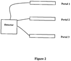
Figure 2 is a schematic diagram of a multiple portal arrangement. -
Figure 1 shows a portal orgateway 10 through which a person has to pass to enter a secure or controlled area in, for example, an airport. This has anopen aluminium framework 12 with an upperhorizontal lintel 14 and two opposingvertical supports vertical supports 16 is an open, non-resonantoptical sample cell 18, each end of which is defined by amirror 20. By open it is meant that there is no physical barrier between theoptical cell 18 and the portal opening 22. In order to ensure that as many molecules as possible enter thecell 18 without adsorption losses, thecell 18 extends along the entire vertical extent of thesupport 16. Hence, in practice, preferably theopen sample cell 18 is longer than 1 metre, and ideally longer than 1.5 metres. - The use of an entirely open and relatively long
optical cell 18 is a key advantage when detecting low gas concentrations, for example parts per billion. Were gas pumped into a closed cell, molecules would stick to the cell walls, and may be detectable for a long period after the cell has been refreshed. This could create false positives and reduce response time. To avoid this problem, the entire cell could be heated. However, this is not necessary using the open framework of the present invention, as the long length and open configuration prevent sticking and provide very quick cell refresh rates and far faster measurement times. - On the
support 17 opposite thesample cell 18 is provided a series offans 24 arranged to blow air substantially horizontally towards thesample cell 18. This ensures that the general direction of airflow is into thesample cell 18.Optionally fans 26 may be provided on thesample cell support 16 to draw air towards it, thereby augmenting the pull on molecules into thecell 18. Thesefans 26 also help speed up the refresh rate of the cell. - Light from a
quantum cascade laser 28 is coupled into the cell using afibre optic cable 30, A step function electrical pulse is applied to thequantum cascade laser 28 to cause it to output a continuous wavelength chirp. Preferably, each applied pulse has a duration that is greater than 150ns, in particular greater than 200ns. Preferably, each applied pulse has a duration that is in the range of 150 to 300ns, preferably 200 to 300ns. This can provide a tuning range of about 60GHz. - The continuous wavelength chirp is injected into the
optical cell 18 via theoptical fibre coupling 30. The wavelength variation provided by this is used as an intra-pulse scan. The chirp rate is selected to substantially prevent light interference occurring in the optical cell. In particular, the chirp rate may be selected so that there is a time delay between spots on the mirrors of the non-resonant cell sufficient to substantially prevent light interference from occurring, wherein the spots define locations at which the injected chirp is reflected from the cell mirrors. This ensures that operation of the detector is fringe free. Techniques for doing this are described inWO03087787 - Light injected into the
cell 18 undergoes multiple passes. In order to provide a high level of sensitivity, preferably thecell 18 is arranged to provide 100 or more passes. Light emitted from thecell 18 is coupled to adetector 32 using afibre optic cable 34. The wavelength variation of the applied chirped pulses is sufficient to allow the chemical fingerprint of curtain materials to be detected, for example peroxide and EGDN. In this way, the detected light can be used to unambiguously identify certain chemicals, in particular some hazardous or undesirable materials, by for example comparing the detected fingerprint with stored fingerprints for known materials. Whilst ideally a positive identification of a chemical is achieved, optionally, unexplained signals could be used to give low level alerts. - Using a quantum cascade laser in this arrangement provides numerous advantages. Because of its very rapid response rate, the measurement time can be significantly reduced compared to other arrangements. Also, because the
sample cell 18 is completely open, no losses are incurred through transport lines or other types of sample collection arrangement. In addition, the overall measurement is significantly more sensitive than other conventional measurements. - A skilled person will appreciate that variations of the enclosed arrangement are possible. For example, whilst the invention has been described in terms of a portal for a person to walk through, it could equally be a portal or opening or gateway through which goods have to pass before, for example, entering a secure or controlled area. Equably, although
Figure 1 shows a single portal, a plurality of these could be provided, with their outputs fed to a single detector unit, as shown inFigure 2 . Accordingly, the above description of the specific embodiment is made by way of example only and not for the purposes of limitations. It will be clear to the skilled person that minor modifications may be made.
Claims (14)
- A portal or gateway (10) adapted to allow people or items to pass through, wherein the portal or gateway (10) has a vertical support (16), a laser adapted to generate chirped light (28), an open optical sample cell (18) and a detector (32) for detecting light from the laser (28) that has passed through the open optical sample cell (18), wherein the open optical sample cell (18) is defined by a mirror (20) at each end, the mirrors (20) being included in the vertical support (16), so that the open optical sample cell (18) extends along the vertical support (16).
- A portal or gateway (10) as claimed in claim 1 wherein the sample cell (18) is arranged so that light makes multiple passes through it.
- A portal or gateway (10) as claimed in claim 2, wherein the cell (18) is arranged so that light makes one hundred or more passes through the cell (18).
- A portal or gateway (10) as claimed in any of the preceding claims wherein the open sample cell (18) extends along substantially the full length of the portal (10).
- A portal or gateway (10) as claimed in any of the preceding claims wherein the open sample cell (18) is longer than 1 metre.
- A portal or gateway (10) as claimed in claim 5 wherein the open sample cell (18) is longer than 1.5 metres.
- A portal or gateway (10) as claimed in any of the preceding claims comprising means for directing gas in the portal towards the open cell (18).
- A portal or gateway (10) as claimed in any of the preceding claims wherein the laser (28) is a semiconductor laser, for example a semiconductor diode laser, preferably a quantum cascade laser (28).
- A portal or gateway (10) as claimed in claim 8 wherein the chirped light is generated by applying a one or a series of substantially step function electrical pulses to the semiconductor diode laser (28) to cause the laser to output one or more pulses, each having a continuous wavelength chirp, for injecting into the optical cell (18).
- A portal or gateway (10) as claimed in claim 9 wherein each applied pulse has a duration that is in the range of 150 to 300ns.
- A portal or gateway (10) as claimed in claim 9 or claim 10, wherein the portal has means for selecting a chirp rate associated with the chirped light and wherein the chirp rate is selected so that there is a time delay between spots on the mirrors (20) of the cell (18) sufficient to substantially prevent light interference from occurring, wherein the spots define locations at which the injected chirp is reflected from the cell mirrors (20).
- A portal or gateway (10) as claimed in any of the preceding claims, wherein the cell (18) is non-resonant.
- A system comprising a plurality of portals or gateways (10) as defined in the preceding claims.
- A system as claimed in claim 13 wherein light from the plurality of portals or gateways (10) is passed to the single detector (32) using fibre optic cable.
Applications Claiming Priority (2)
| Application Number | Priority Date | Filing Date | Title |
|---|---|---|---|
| GBGB0623812.5A GB0623812D0 (en) | 2006-11-29 | 2006-11-29 | Portal |
| PCT/GB2007/004333 WO2008065338A1 (en) | 2006-11-29 | 2007-11-12 | Portal |
Publications (2)
| Publication Number | Publication Date |
|---|---|
| EP2097734A1 EP2097734A1 (en) | 2009-09-09 |
| EP2097734B1 true EP2097734B1 (en) | 2016-02-24 |
Family
ID=37671507
Family Applications (1)
| Application Number | Title | Priority Date | Filing Date |
|---|---|---|---|
| EP07824559.4A Active EP2097734B1 (en) | 2006-11-29 | 2007-11-12 | Portal |
Country Status (10)
| Country | Link |
|---|---|
| US (1) | US8339606B2 (en) |
| EP (1) | EP2097734B1 (en) |
| JP (1) | JP5347119B2 (en) |
| KR (1) | KR101544995B1 (en) |
| CN (1) | CN101600956B (en) |
| AU (1) | AU2007327386B2 (en) |
| CA (1) | CA2673816C (en) |
| GB (1) | GB0623812D0 (en) |
| RU (1) | RU2484449C2 (en) |
| WO (1) | WO2008065338A1 (en) |
Families Citing this family (9)
| Publication number | Priority date | Publication date | Assignee | Title |
|---|---|---|---|---|
| GB201004353D0 (en) * | 2010-03-16 | 2010-04-28 | Cascade Technologies Ltd | Multiple pathlength gas cell |
| CA2756199C (en) * | 2010-10-28 | 2016-11-29 | Teknoscan Systems Inc. | Transportable portal for detection of illicit substances |
| US20140078493A1 (en) * | 2012-09-19 | 2014-03-20 | Elwha Llc | System and method for removing surface particles from an object |
| US9134205B2 (en) | 2012-09-19 | 2015-09-15 | Elwha Llc | System and method for removing surface particles from an object |
| CN104375144A (en) * | 2013-08-15 | 2015-02-25 | 同方威视技术股份有限公司 | Millimeter wave three-dimensional holoscan imaging device and human or object checking method |
| CA160409S (en) * | 2014-07-18 | 2015-10-19 | Thales Comm & Security Sas | Automatic access gate |
| WO2017065815A1 (en) | 2015-10-17 | 2017-04-20 | General Electric Company | Gas detector and method of detection |
| US10054530B2 (en) * | 2016-08-16 | 2018-08-21 | General Electric Company | Particle detection systems |
| CN113256975B (en) * | 2021-05-12 | 2022-04-26 | 中国民航大学 | A method for determining the influence range of airport landside road traffic congestion based on cascading failure |
Citations (1)
| Publication number | Priority date | Publication date | Assignee | Title |
|---|---|---|---|---|
| US5866430A (en) * | 1996-06-13 | 1999-02-02 | Grow; Ann E. | Raman optrode processes and devices for detection of chemicals and microorganisms |
Family Cites Families (23)
| Publication number | Priority date | Publication date | Assignee | Title |
|---|---|---|---|---|
| JPS60140141A (en) * | 1983-12-27 | 1985-07-25 | Fujitsu Ltd | Optical gas sensor |
| JPS6234034A (en) * | 1985-08-07 | 1987-02-14 | Toshiba Corp | Optical fiber apparatus for illumination and its preparation |
| JPS63285446A (en) * | 1987-05-19 | 1988-11-22 | Toshiba Corp | Photometry of automatic chemical analyzer |
| JP2560362B2 (en) * | 1987-12-18 | 1996-12-04 | 富士通株式会社 | Multiple reflector |
| US4987767A (en) * | 1989-06-09 | 1991-01-29 | Research Corporation Technologies, Inc. | Exposive detection screening system |
| US6040191A (en) * | 1996-06-13 | 2000-03-21 | Grow; Ann E. | Raman spectroscopic method for determining the ligand binding capacity of biologicals |
| WO1999021148A1 (en) | 1997-10-22 | 1999-04-29 | Ids Intelligent Detection Systems, Inc. | An integrated walk-through personnel scanner system for security portals |
| RU2129289C1 (en) * | 1998-01-20 | 1999-04-20 | Научно-производственный центр "Аспект" | Gear detecting radioactive materials |
| US6708572B2 (en) * | 2000-12-22 | 2004-03-23 | General Electric Company | Portal trace detection systems for detection of imbedded particles |
| US7583710B2 (en) * | 2001-01-30 | 2009-09-01 | Board Of Trustees Operating Michigan State University | Laser and environmental monitoring system |
| US6610977B2 (en) * | 2001-10-01 | 2003-08-26 | Lockheed Martin Corporation | Security system for NBC-safe building |
| US20080053252A1 (en) * | 2001-12-20 | 2008-03-06 | Anthony Jenkins | Portal trace detection systems for detection of imbedded particles |
| GB0208100D0 (en) * | 2002-04-09 | 2002-05-22 | Univ Strathclyde | Semiconductor diode laser spectrometer arrangement |
| US6870791B1 (en) | 2002-12-26 | 2005-03-22 | David D. Caulfield | Acoustic portal detection system |
| US20040124376A1 (en) | 2002-12-27 | 2004-07-01 | Canberra Auila Inc. | Real time explosive detection system |
| US20050124869A1 (en) * | 2003-12-08 | 2005-06-09 | John Hefti | Non-invasive, in vivo substance measurement systems |
| US7180441B2 (en) * | 2004-04-14 | 2007-02-20 | Safeview, Inc. | Multi-sensor surveillance portal |
| PL1586514T3 (en) * | 2004-04-16 | 2009-03-31 | Lindal Ventil Gmbh | Atomiser for a container with a valve |
| JP2005140794A (en) * | 2005-01-13 | 2005-06-02 | E Graw An | Raman opto load process and device for detecting chemical substance and microorganism |
| EP1866614A4 (en) | 2005-02-23 | 2012-04-04 | Global Security Devices Ltd | System and method for detecting concealed objects |
| US7401498B2 (en) * | 2005-03-07 | 2008-07-22 | Syagen Technology | Multiple trace portal detection systems |
| US20100282960A1 (en) * | 2007-12-26 | 2010-11-11 | Clark Keith A | Combined imaging and trace-detection inspection system and method |
| US8149115B2 (en) * | 2009-03-26 | 2012-04-03 | Gianni Arcaini | Explosive detection portal |
-
2006
- 2006-11-29 GB GBGB0623812.5A patent/GB0623812D0/en not_active Ceased
-
2007
- 2007-11-12 RU RU2009124429/28A patent/RU2484449C2/en active
- 2007-11-12 AU AU2007327386A patent/AU2007327386B2/en not_active Ceased
- 2007-11-12 WO PCT/GB2007/004333 patent/WO2008065338A1/en not_active Ceased
- 2007-11-12 KR KR1020097013292A patent/KR101544995B1/en not_active Expired - Fee Related
- 2007-11-12 US US12/516,947 patent/US8339606B2/en active Active
- 2007-11-12 JP JP2009538764A patent/JP5347119B2/en not_active Expired - Fee Related
- 2007-11-12 CA CA2673816A patent/CA2673816C/en not_active Expired - Fee Related
- 2007-11-12 EP EP07824559.4A patent/EP2097734B1/en active Active
- 2007-11-12 CN CN200780050535.8A patent/CN101600956B/en active Active
Patent Citations (1)
| Publication number | Priority date | Publication date | Assignee | Title |
|---|---|---|---|---|
| US5866430A (en) * | 1996-06-13 | 1999-02-02 | Grow; Ann E. | Raman optrode processes and devices for detection of chemicals and microorganisms |
Non-Patent Citations (1)
| Title |
|---|
| ERWAN NORMAND ET AL: "QUANTUM CASCADE LASER (QCL) BASED SENSOR FOR THE DETECTION OF EXPLOSIVE COMPOUNDS", PROCEEDINGS OF SPIE, vol. 6402, 27 September 2006 (2006-09-27), pages 64020G - 64020G-12, XP055133875, ISSN: 0277-786X, DOI: 10.1117/12.695423 * |
Also Published As
| Publication number | Publication date |
|---|---|
| JP5347119B2 (en) | 2013-11-20 |
| JP2010511168A (en) | 2010-04-08 |
| CA2673816C (en) | 2016-07-26 |
| AU2007327386A1 (en) | 2008-06-05 |
| CN101600956B (en) | 2014-03-19 |
| KR20090112639A (en) | 2009-10-28 |
| US20100067014A1 (en) | 2010-03-18 |
| WO2008065338A1 (en) | 2008-06-05 |
| RU2009124429A (en) | 2011-01-10 |
| EP2097734A1 (en) | 2009-09-09 |
| KR101544995B1 (en) | 2015-08-17 |
| CA2673816A1 (en) | 2008-06-05 |
| RU2484449C2 (en) | 2013-06-10 |
| WO2008065338A8 (en) | 2009-07-23 |
| CN101600956A (en) | 2009-12-09 |
| AU2007327386B2 (en) | 2012-11-08 |
| GB0623812D0 (en) | 2007-01-10 |
| US8339606B2 (en) | 2012-12-25 |
Similar Documents
| Publication | Publication Date | Title |
|---|---|---|
| US8339606B2 (en) | Portal | |
| US4496839A (en) | System and method for remote detection and identification of chemical species by laser initiated nonresonant infrared spectroscopy | |
| Nambayah et al. | A quantitative assessment of chemical techniques for detecting traces of explosives at counter-terrorist portals | |
| US9546953B2 (en) | Method and apparatus for real-time analysis of chemical, biological and explosive substances in the air | |
| US8653462B2 (en) | Methods and systems for detecting terahertz radiation by radiation enhanced emission of fluorescence | |
| CA2673810A1 (en) | Multi mode fibre perturber | |
| EP2889608B1 (en) | Inspection methods and apparatuses for inspection of liquids | |
| CN101539017A (en) | Device and method for analyzing oil-water-gas by using terahertz radiation | |
| NL1041826B1 (en) | Frequency comb for downhole chemical sensing. | |
| US8218146B2 (en) | System and method for detecting a target substance | |
| US7796264B2 (en) | Method and system for enhanced remote detection of low concentration vapors | |
| Pal et al. | Differential absorption lidar CO 2 laser system for remote sensing of TATP related gases | |
| Normand et al. | Quantum cascade laser (QCL) based sensor for the detection of explosive compounds | |
| Kendziora et al. | Detection of trace explosives on relevant substrates using a mobile platform for photothermal infrared imaging spectroscopy (PT-IRIS) | |
| US20110095189A1 (en) | Tactical chemical biological threat detection | |
| Rayner et al. | Remote explosive and chemical agent detection using broadly tunable mid-infrared external cavity quantum cascade lasers | |
| Zhang et al. | Applications of terahertz spectroscopy | |
| CN107690576A (en) | Radioactive anomaly detector | |
| Deng et al. | Terahertz wave reference-free transmission spectroscopy of aminophenol | |
| Mędrzycki et al. | P10-Project of the Security Portals for Explosives Detection using CEAS Sensor | |
| Linker | Explosives Detection Personnel Portals | |
| US20110228270A1 (en) | Open-Path Near Real-Time Full Wall Emissions Monitoring Method | |
| Normand et al. | Advances in quantum cascade lasers for security and crime-fighting | |
| Stokes et al. | The fusion of MIR absorbance and NIR Raman spectroscopic techniques for identification of improvised explosive materials in multiple scenarios | |
| Murty et al. | Diurnal variation of boundary layer using different methods |
Legal Events
| Date | Code | Title | Description |
|---|---|---|---|
| PUAI | Public reference made under article 153(3) epc to a published international application that has entered the european phase |
Free format text: ORIGINAL CODE: 0009012 |
|
| 17P | Request for examination filed |
Effective date: 20090608 |
|
| AK | Designated contracting states |
Kind code of ref document: A1 Designated state(s): AT BE BG CH CY CZ DE DK EE ES FI FR GB GR HU IE IS IT LI LT LU LV MC MT NL PL PT RO SE SI SK TR |
|
| DAX | Request for extension of the european patent (deleted) | ||
| 17Q | First examination report despatched |
Effective date: 20111206 |
|
| RAP1 | Party data changed (applicant data changed or rights of an application transferred) |
Owner name: CASCADE TECHNOLOGIES HOLDINGS LIMITED |
|
| GRAP | Despatch of communication of intention to grant a patent |
Free format text: ORIGINAL CODE: EPIDOSNIGR1 |
|
| RIC1 | Information provided on ipc code assigned before grant |
Ipc: G01N 21/35 20140101AFI20150916BHEP Ipc: G01N 21/3504 20140101ALI20150916BHEP Ipc: G01N 21/03 20060101ALI20150916BHEP Ipc: G01N 21/31 20060101ALI20150916BHEP Ipc: G01N 21/39 20060101ALI20150916BHEP Ipc: G01V 5/00 20060101ALI20150916BHEP |
|
| INTG | Intention to grant announced |
Effective date: 20151021 |
|
| RIN1 | Information on inventor provided before grant (corrected) |
Inventor name: HOWIESON, IAIN |
|
| GRAS | Grant fee paid |
Free format text: ORIGINAL CODE: EPIDOSNIGR3 |
|
| GRAA | (expected) grant |
Free format text: ORIGINAL CODE: 0009210 |
|
| AK | Designated contracting states |
Kind code of ref document: B1 Designated state(s): AT BE BG CH CY CZ DE DK EE ES FI FR GB GR HU IE IS IT LI LT LU LV MC MT NL PL PT RO SE SI SK TR |
|
| REG | Reference to a national code |
Ref country code: GB Ref legal event code: FG4D |
|
| REG | Reference to a national code |
Ref country code: CH Ref legal event code: EP |
|
| REG | Reference to a national code |
Ref country code: AT Ref legal event code: REF Ref document number: 776978 Country of ref document: AT Kind code of ref document: T Effective date: 20160315 |
|
| REG | Reference to a national code |
Ref country code: IE Ref legal event code: FG4D |
|
| REG | Reference to a national code |
Ref country code: DE Ref legal event code: R096 Ref document number: 602007044984 Country of ref document: DE |
|
| REG | Reference to a national code |
Ref country code: LT Ref legal event code: MG4D |
|
| REG | Reference to a national code |
Ref country code: NL Ref legal event code: MP Effective date: 20160224 |
|
| REG | Reference to a national code |
Ref country code: AT Ref legal event code: MK05 Ref document number: 776978 Country of ref document: AT Kind code of ref document: T Effective date: 20160224 |
|
| PG25 | Lapsed in a contracting state [announced via postgrant information from national office to epo] |
Ref country code: GR Free format text: LAPSE BECAUSE OF FAILURE TO SUBMIT A TRANSLATION OF THE DESCRIPTION OR TO PAY THE FEE WITHIN THE PRESCRIBED TIME-LIMIT Effective date: 20160525 Ref country code: FI Free format text: LAPSE BECAUSE OF FAILURE TO SUBMIT A TRANSLATION OF THE DESCRIPTION OR TO PAY THE FEE WITHIN THE PRESCRIBED TIME-LIMIT Effective date: 20160224 Ref country code: IT Free format text: LAPSE BECAUSE OF FAILURE TO SUBMIT A TRANSLATION OF THE DESCRIPTION OR TO PAY THE FEE WITHIN THE PRESCRIBED TIME-LIMIT Effective date: 20160224 Ref country code: ES Free format text: LAPSE BECAUSE OF FAILURE TO SUBMIT A TRANSLATION OF THE DESCRIPTION OR TO PAY THE FEE WITHIN THE PRESCRIBED TIME-LIMIT Effective date: 20160224 |
|
| PG25 | Lapsed in a contracting state [announced via postgrant information from national office to epo] |
Ref country code: AT Free format text: LAPSE BECAUSE OF FAILURE TO SUBMIT A TRANSLATION OF THE DESCRIPTION OR TO PAY THE FEE WITHIN THE PRESCRIBED TIME-LIMIT Effective date: 20160224 Ref country code: NL Free format text: LAPSE BECAUSE OF FAILURE TO SUBMIT A TRANSLATION OF THE DESCRIPTION OR TO PAY THE FEE WITHIN THE PRESCRIBED TIME-LIMIT Effective date: 20160224 Ref country code: PL Free format text: LAPSE BECAUSE OF FAILURE TO SUBMIT A TRANSLATION OF THE DESCRIPTION OR TO PAY THE FEE WITHIN THE PRESCRIBED TIME-LIMIT Effective date: 20160224 Ref country code: PT Free format text: LAPSE BECAUSE OF FAILURE TO SUBMIT A TRANSLATION OF THE DESCRIPTION OR TO PAY THE FEE WITHIN THE PRESCRIBED TIME-LIMIT Effective date: 20160624 Ref country code: SE Free format text: LAPSE BECAUSE OF FAILURE TO SUBMIT A TRANSLATION OF THE DESCRIPTION OR TO PAY THE FEE WITHIN THE PRESCRIBED TIME-LIMIT Effective date: 20160224 Ref country code: LV Free format text: LAPSE BECAUSE OF FAILURE TO SUBMIT A TRANSLATION OF THE DESCRIPTION OR TO PAY THE FEE WITHIN THE PRESCRIBED TIME-LIMIT Effective date: 20160224 Ref country code: LT Free format text: LAPSE BECAUSE OF FAILURE TO SUBMIT A TRANSLATION OF THE DESCRIPTION OR TO PAY THE FEE WITHIN THE PRESCRIBED TIME-LIMIT Effective date: 20160224 |
|
| PG25 | Lapsed in a contracting state [announced via postgrant information from national office to epo] |
Ref country code: DK Free format text: LAPSE BECAUSE OF FAILURE TO SUBMIT A TRANSLATION OF THE DESCRIPTION OR TO PAY THE FEE WITHIN THE PRESCRIBED TIME-LIMIT Effective date: 20160224 Ref country code: EE Free format text: LAPSE BECAUSE OF FAILURE TO SUBMIT A TRANSLATION OF THE DESCRIPTION OR TO PAY THE FEE WITHIN THE PRESCRIBED TIME-LIMIT Effective date: 20160224 |
|
| REG | Reference to a national code |
Ref country code: FR Ref legal event code: PLFP Year of fee payment: 10 |
|
| REG | Reference to a national code |
Ref country code: DE Ref legal event code: R097 Ref document number: 602007044984 Country of ref document: DE |
|
| PG25 | Lapsed in a contracting state [announced via postgrant information from national office to epo] |
Ref country code: CZ Free format text: LAPSE BECAUSE OF FAILURE TO SUBMIT A TRANSLATION OF THE DESCRIPTION OR TO PAY THE FEE WITHIN THE PRESCRIBED TIME-LIMIT Effective date: 20160224 Ref country code: RO Free format text: LAPSE BECAUSE OF FAILURE TO SUBMIT A TRANSLATION OF THE DESCRIPTION OR TO PAY THE FEE WITHIN THE PRESCRIBED TIME-LIMIT Effective date: 20160224 Ref country code: SK Free format text: LAPSE BECAUSE OF FAILURE TO SUBMIT A TRANSLATION OF THE DESCRIPTION OR TO PAY THE FEE WITHIN THE PRESCRIBED TIME-LIMIT Effective date: 20160224 |
|
| PG25 | Lapsed in a contracting state [announced via postgrant information from national office to epo] |
Ref country code: BE Free format text: LAPSE BECAUSE OF FAILURE TO SUBMIT A TRANSLATION OF THE DESCRIPTION OR TO PAY THE FEE WITHIN THE PRESCRIBED TIME-LIMIT Effective date: 20160224 |
|
| PLBE | No opposition filed within time limit |
Free format text: ORIGINAL CODE: 0009261 |
|
| STAA | Information on the status of an ep patent application or granted ep patent |
Free format text: STATUS: NO OPPOSITION FILED WITHIN TIME LIMIT |
|
| 26N | No opposition filed |
Effective date: 20161125 |
|
| PG25 | Lapsed in a contracting state [announced via postgrant information from national office to epo] |
Ref country code: BG Free format text: LAPSE BECAUSE OF FAILURE TO SUBMIT A TRANSLATION OF THE DESCRIPTION OR TO PAY THE FEE WITHIN THE PRESCRIBED TIME-LIMIT Effective date: 20160524 Ref country code: SI Free format text: LAPSE BECAUSE OF FAILURE TO SUBMIT A TRANSLATION OF THE DESCRIPTION OR TO PAY THE FEE WITHIN THE PRESCRIBED TIME-LIMIT Effective date: 20160224 |
|
| REG | Reference to a national code |
Ref country code: CH Ref legal event code: PL |
|
| PG25 | Lapsed in a contracting state [announced via postgrant information from national office to epo] |
Ref country code: LI Free format text: LAPSE BECAUSE OF NON-PAYMENT OF DUE FEES Effective date: 20161130 Ref country code: CH Free format text: LAPSE BECAUSE OF NON-PAYMENT OF DUE FEES Effective date: 20161130 |
|
| REG | Reference to a national code |
Ref country code: IE Ref legal event code: MM4A |
|
| PG25 | Lapsed in a contracting state [announced via postgrant information from national office to epo] |
Ref country code: LU Free format text: LAPSE BECAUSE OF NON-PAYMENT OF DUE FEES Effective date: 20161130 |
|
| REG | Reference to a national code |
Ref country code: FR Ref legal event code: PLFP Year of fee payment: 11 |
|
| PG25 | Lapsed in a contracting state [announced via postgrant information from national office to epo] |
Ref country code: IE Free format text: LAPSE BECAUSE OF NON-PAYMENT OF DUE FEES Effective date: 20161112 |
|
| PG25 | Lapsed in a contracting state [announced via postgrant information from national office to epo] |
Ref country code: HU Free format text: LAPSE BECAUSE OF FAILURE TO SUBMIT A TRANSLATION OF THE DESCRIPTION OR TO PAY THE FEE WITHIN THE PRESCRIBED TIME-LIMIT; INVALID AB INITIO Effective date: 20071112 Ref country code: CY Free format text: LAPSE BECAUSE OF FAILURE TO SUBMIT A TRANSLATION OF THE DESCRIPTION OR TO PAY THE FEE WITHIN THE PRESCRIBED TIME-LIMIT Effective date: 20160224 |
|
| PG25 | Lapsed in a contracting state [announced via postgrant information from national office to epo] |
Ref country code: IS Free format text: LAPSE BECAUSE OF FAILURE TO SUBMIT A TRANSLATION OF THE DESCRIPTION OR TO PAY THE FEE WITHIN THE PRESCRIBED TIME-LIMIT Effective date: 20160224 Ref country code: TR Free format text: LAPSE BECAUSE OF FAILURE TO SUBMIT A TRANSLATION OF THE DESCRIPTION OR TO PAY THE FEE WITHIN THE PRESCRIBED TIME-LIMIT Effective date: 20160224 Ref country code: MC Free format text: LAPSE BECAUSE OF FAILURE TO SUBMIT A TRANSLATION OF THE DESCRIPTION OR TO PAY THE FEE WITHIN THE PRESCRIBED TIME-LIMIT Effective date: 20160224 |
|
| PG25 | Lapsed in a contracting state [announced via postgrant information from national office to epo] |
Ref country code: MT Free format text: LAPSE BECAUSE OF NON-PAYMENT OF DUE FEES Effective date: 20161112 |
|
| PGFP | Annual fee paid to national office [announced via postgrant information from national office to epo] |
Ref country code: DE Payment date: 20201020 Year of fee payment: 14 |
|
| REG | Reference to a national code |
Ref country code: GB Ref legal event code: 732E Free format text: REGISTERED BETWEEN 20220310 AND 20220316 |
|
| REG | Reference to a national code |
Ref country code: DE Ref legal event code: R119 Ref document number: 602007044984 Country of ref document: DE |
|
| PG25 | Lapsed in a contracting state [announced via postgrant information from national office to epo] |
Ref country code: DE Free format text: LAPSE BECAUSE OF NON-PAYMENT OF DUE FEES Effective date: 20220601 |
|
| P01 | Opt-out of the competence of the unified patent court (upc) registered |
Effective date: 20230529 |
|
| P02 | Opt-out of the competence of the unified patent court (upc) changed |
Effective date: 20230622 |
|
| PGFP | Annual fee paid to national office [announced via postgrant information from national office to epo] |
Ref country code: GB Payment date: 20251023 Year of fee payment: 19 |
|
| PGFP | Annual fee paid to national office [announced via postgrant information from national office to epo] |
Ref country code: FR Payment date: 20251023 Year of fee payment: 19 |