EP2097209B1 - Laser machining - Google Patents
Laser machining Download PDFInfo
- Publication number
- EP2097209B1 EP2097209B1 EP07846853.5A EP07846853A EP2097209B1 EP 2097209 B1 EP2097209 B1 EP 2097209B1 EP 07846853 A EP07846853 A EP 07846853A EP 2097209 B1 EP2097209 B1 EP 2097209B1
- Authority
- EP
- European Patent Office
- Prior art keywords
- laser
- machining
- pulses
- scan
- substrate
- Prior art date
- Legal status (The legal status is an assumption and is not a legal conclusion. Google has not performed a legal analysis and makes no representation as to the accuracy of the status listed.)
- Not-in-force
Links
Images
Classifications
-
- B—PERFORMING OPERATIONS; TRANSPORTING
- B23—MACHINE TOOLS; METAL-WORKING NOT OTHERWISE PROVIDED FOR
- B23K—SOLDERING OR UNSOLDERING; WELDING; CLADDING OR PLATING BY SOLDERING OR WELDING; CUTTING BY APPLYING HEAT LOCALLY, e.g. FLAME CUTTING; WORKING BY LASER BEAM
- B23K26/00—Working by laser beam, e.g. welding, cutting or boring
- B23K26/02—Positioning or observing the workpiece, e.g. with respect to the point of impact; Aligning, aiming or focusing the laser beam
- B23K26/06—Shaping the laser beam, e.g. by masks or multi-focusing
- B23K26/062—Shaping the laser beam, e.g. by masks or multi-focusing by direct control of the laser beam
- B23K26/0622—Shaping the laser beam, e.g. by masks or multi-focusing by direct control of the laser beam by shaping pulses
-
- B—PERFORMING OPERATIONS; TRANSPORTING
- B23—MACHINE TOOLS; METAL-WORKING NOT OTHERWISE PROVIDED FOR
- B23K—SOLDERING OR UNSOLDERING; WELDING; CLADDING OR PLATING BY SOLDERING OR WELDING; CUTTING BY APPLYING HEAT LOCALLY, e.g. FLAME CUTTING; WORKING BY LASER BEAM
- B23K26/00—Working by laser beam, e.g. welding, cutting or boring
- B23K26/08—Devices involving relative movement between laser beam and workpiece
-
- B—PERFORMING OPERATIONS; TRANSPORTING
- B23—MACHINE TOOLS; METAL-WORKING NOT OTHERWISE PROVIDED FOR
- B23K—SOLDERING OR UNSOLDERING; WELDING; CLADDING OR PLATING BY SOLDERING OR WELDING; CUTTING BY APPLYING HEAT LOCALLY, e.g. FLAME CUTTING; WORKING BY LASER BEAM
- B23K26/00—Working by laser beam, e.g. welding, cutting or boring
- B23K26/352—Working by laser beam, e.g. welding, cutting or boring for surface treatment
- B23K26/3568—Modifying rugosity
- B23K26/3576—Diminishing rugosity, e.g. grinding; Polishing; Smoothing
-
- B—PERFORMING OPERATIONS; TRANSPORTING
- B23—MACHINE TOOLS; METAL-WORKING NOT OTHERWISE PROVIDED FOR
- B23K—SOLDERING OR UNSOLDERING; WELDING; CLADDING OR PLATING BY SOLDERING OR WELDING; CUTTING BY APPLYING HEAT LOCALLY, e.g. FLAME CUTTING; WORKING BY LASER BEAM
- B23K2103/00—Materials to be soldered, welded or cut
- B23K2103/50—Inorganic material, e.g. metals, not provided for in B23K2103/02 – B23K2103/26
- B23K2103/56—Inorganic material, e.g. metals, not provided for in B23K2103/02 – B23K2103/26 semiconducting
Definitions
- This invention relates to a method of laser machining according to the preamble of claim 1. Such a method is discribed in WO 00/10037 A .
- Laser micro-machining with state of the art solid state lasers typically involves the use of lasers with galvanometer scanners to position a focussed laser beam on the surface of a wafer or substrate to be machined.
- these lasers operate at repetition rates of 30 to 200 kHz and scanning occurs at velocities such that individual focussed laser spots overlap to some extent to form a shallow trench or scribe line.
- multiple lines or passes 11 are used in this way to cut through or to dice, i.e. singulate, semiconductor devices 12. This process is described in, for example, EP 1328372 .
- laser dicing is accomplished by scanning a laser beam across a substrate.
- successive adjacent pulses 21 are placed to have a certain overlap by scanning the laser beam at a particular scan speed to give a substantial overlap between the pulses.
- the scan is repeated in a number of passes 11, until the substrate is fully diced through. As shown in Figure 3 , this results in dicing with a relatively smooth edge 31.
- Figures 4 and 5 if the overlap of pulses 41 is reduced the die can appear to have a 'scalloped' edge 51.
- WO 00/10037 A discloses scanning a pulsed laser beam for surface ablation, of, for example, a cornea. Consecutive pulses in each pass are well separated and uniformly disposed. Scanning is preferably in concentric rings with a scanning speed selected according to a perimeter of the ring. The repetition rate is in the range 0.2 kHz to 10 kHz. The disclosure teaches away from multiple scanning where pulses of a second scan partially overlap pulses of a first scan and teaches instead a ring perimeter filled uniformly and precisely by pulses in, for example, two successive scans in which pulses from a second scan alternate precisely with pulses of a first scan.
- US 6,023,040 discloses a method for laser assisted polishing of a material layer to a desired surface, the method comprising the steps of: (a) setting up a laser beam in an XYZ coordinate system to ablate spurious material from the material layer at the desired surface; and (b) scanning the laser beam across the material layer such that consecutive laser beam pulses irradiate at least partially non-overlapping portions of the material layer and laser beam pulses from different directions in the XYZ coordinate system successively irradiate a given area of the material layer.
- the method can be employed for planarization of semiconductor wafers.
- WO 99/34742 discloses a method of laser ablation of tissue such as a cornea using concentric scans. Alternatively linear or random scans may be made. A first scan is defined in an ablation zone on the tissue to be ablated. A plurality of laser beam ablation points along the first scan are defined, two or more passes along the scan are performed, and only non-adjacent laser beam ablation points along the first scan are ablated during each pass. The two or more passes along the one scan result in a single ablation of each laser beam ablation point.
- successive pulses are sufficiently separated on the substrate that a plume produced by a laser pulse does not substantially absorb energy from a succeeding pulse.
- the method comprises machining with a pulse repetition rate of 200 kHz to 300 kHz.
- the method comprises complete dicing or slot cutting through the substrate.
- the machining comprises a laser dicing process for semiconductor dicing.
- the machining comprises slot drilling.
- successive pulses 71, 74 are separated sufficiently such that there is substantially no interaction of a current pulse 74 with a plume 73 produced by a previous pulse 71. Since no energy of the pulse is absorbed in the plume of a previous pulse, the overall material removal rate from the substrate 72 is increased.
- each successive pass 82, 83, 84 of the laser beam is offset from a previous pass 81, 82, 83 respectively. In this manner, progressively straighter edges 92, 93, 94 of the scanned feature are produced with each pass.
- the invention provides a method for laser scribing, dicing or machining of semiconductor substrates with improved edge quality, throughput and debris control using multiple pass machining with non-overlapping spatial distribution of pulses in each individual pass, but with pulses in succeeding passes offset from pulses in previous passes.
- This laser machining with zero overlap substantially prevents pulse-plume interaction, and hence substantially eliminates any loss of energy of a succeeding pulse to a plume produced by a previous pulse.
- a pulsed laser is used to scan spatially in a direction to be machined. Multiple scans of the laser are used to form a scribe or through feature.
- the scanning velocity V g and repetition rate R of the pulses is such that pulses do not overlap.
- a repetition range of 200 kHz to 300 kHz has been found to be suitable.
- Individual scans of the laser are positioned spatially to overlap with preceding scans by synchronising and use of a time delay in pulse emission from the laser.
- the laser parameters used are described in Table 1 below.
- the laser ran at 170kHz, which gave a pulse energy at the wafer of ⁇ 60 ⁇ J.
- the scan speed was varied from 500mm/s to 3500mm/s to give overlaps in the range 80% to -50%.
- the overlap was determined from the ablated spot diameter ( ⁇ 14 ⁇ m) rather than the theoretical spot diameter ( ⁇ 8 ⁇ m).
Description
- This invention relates to a method of laser machining according to the preamble of claim 1. Such a method is discribed in
WO 00/10037 A - Laser micro-machining with state of the art solid state lasers typically involves the use of lasers with galvanometer scanners to position a focussed laser beam on the surface of a wafer or substrate to be machined. Typically, these lasers operate at repetition rates of 30 to 200 kHz and scanning occurs at velocities such that individual focussed laser spots overlap to some extent to form a shallow trench or scribe line. As shown in
Figure 1 , multiple lines orpasses 11 are used in this way to cut through or to dice, i.e. singulate,semiconductor devices 12. This process is described in, for example,EP 1328372 . - Thus laser dicing is accomplished by scanning a laser beam across a substrate. Typically, with laser dicing, as shown in
Figure 2 , successiveadjacent pulses 21 are placed to have a certain overlap by scanning the laser beam at a particular scan speed to give a substantial overlap between the pulses. The scan is repeated in a number ofpasses 11, until the substrate is fully diced through. As shown inFigure 3 , this results in dicing with a relativelysmooth edge 31. As shown inFigures 4 and 5 , if the overlap ofpulses 41 is reduced the die can appear to have a 'scalloped'edge 51. - Moreover, as shown in
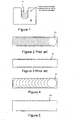
Figure 6 , when alaser pulse 61 ablates material 62 a plume ofdebris 63 is created. If thesubsequent pulse 64 interacts with thedebris plume 63, the succeedinglaser pulse 64 is partially attenuated because the debris plume partially absorbs the energy of the succeeding laser pulse. -
WO 00/10037 A -
US 6,023,040 discloses a method for laser assisted polishing of a material layer to a desired surface, the method comprising the steps of: (a) setting up a laser beam in an XYZ coordinate system to ablate spurious material from the material layer at the desired surface; and (b) scanning the laser beam across the material layer such that consecutive laser beam pulses irradiate at least partially non-overlapping portions of the material layer and laser beam pulses from different directions in the XYZ coordinate system successively irradiate a given area of the material layer. In semiconductor manufacturing technology, it is envisaged that the method can be employed for planarization of semiconductor wafers. -
WO 99/34742 - It is an object of the present invention at least to ameliorate the aforesaid disadvantages in the prior art.
- According to the invention there is provided a method of laser machining a feature, according to claim 1.
- Preferably, successive pulses are sufficiently separated on the substrate that a plume produced by a laser pulse does not substantially absorb energy from a succeeding pulse.
- Conveniently, the method comprises machining with a pulse repetition rate of 200 kHz to 300 kHz.
- Advantageously, the method comprises complete dicing or slot cutting through the substrate.
- Advantageously, the machining comprises a laser dicing process for semiconductor dicing.
- Alternatively, the machining comprises slot drilling.
- The invention will now be described, by way of example, with reference to the accompanying drawings in which:
-
Figure 1 is a schematic transverse cross-sectional view showing successive laser scans across a substrate to form a channel; -
Figure 2 is a schematic plan view of laser pulses on a substrate according to the prior art in which a succeeding laser pulse substantially overlaps a preceding pulse. -
Figure 3 is a schematic plan view of edges of a machined channel using the laser pulse pattern ofFigure 2 ; -
Figure 4 is a schematic plan view of pulses on a substrate in which a succeeding laser pulse overlaps a preceding pulse less than in the pulse pattern ofFigure 2 . -
Figure 5 is a schematic plan view of edges of a machined channel using the laser pulse pattern ofFigure 4 ; -
Figure 6 is a transverse cross-sectional view of laser machining of a substrate using substantially overlapping laser pulses as inFigures 2 and 3 ; -
Figure 7 is a transverse cross-sectional view of laser machining of a substrate according to the invention using substantially non-overlapping pulses; -
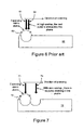
Figure 8 is a schematic plan view of successive offset scans of pulses on a substrate according to the invention using the substantially non-overlapping pulses ofFigure 7 ; -
Figure 9 is a schematic successive plan views of edges of a machined channel using the successive offset scans ofFigure 8 ; and -
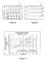
Figure 10 is a graph of theoretical machining speed versus pulse overlap with and without successive scans being offset as they are offset inFigure 8 . - In the Figures, like reference numbers denote like parts.
- The following definitions are used herein:
- Repetition rate, R: The number of pulses per second emitted from the laser.
- Scan Speed, Vg: The scanning velocity of the galvo.
- Linear Overlap, O: The extent of overlap in microns between centres of consecutive pulses at the substrate.
- Kerf diameter, K: Diameter of a specific trench or feature as formed by the laser pulses.
- Pulse spacing, S: The centre-to-centre distance between sequential pulses of a single scan at the substrate.
- Offset dither, D: The centre-to-centre distance between corresponding pulses formed by sequential scans in a multiple pass cutting process.
- Number of Scans, N: The number of consecutive scans required to dice through a substrate.
- Referring to
Figure 7 , in a method according to the invention,successive pulses current pulse 74 with aplume 73 produced by aprevious pulse 71. Since no energy of the pulse is absorbed in the plume of a previous pulse, the overall material removal rate from thesubstrate 72 is increased. - If pulses of successive scans along a same scan line are located in the same positions as the previous scan, a scalloped die edge is produced so a strategy has been developed in accordance with the invention to offset/dither the start position of each pass of the laser beam to smooth the die edge.
- Referring to
Figures 8 and 9 , to smooth thescalloped edge 91 that is created by a firstscan using pulses 81 with a zero overlap strategy, eachsuccessive pass previous pass straighter edges - Thus the invention provides a method for laser scribing, dicing or machining of semiconductor substrates with improved edge quality, throughput and debris control using multiple pass machining with non-overlapping spatial distribution of pulses in each individual pass, but with pulses in succeeding passes offset from pulses in previous passes. This laser machining with zero overlap substantially prevents pulse-plume interaction, and hence substantially eliminates any loss of energy of a succeeding pulse to a plume produced by a previous pulse.
- Thus in the laser machining process according to the invention a pulsed laser is used to scan spatially in a direction to be machined. Multiple scans of the laser are used to form a scribe or through feature. The scanning velocity Vg and repetition rate R of the pulses is such that pulses do not overlap. A repetition range of 200 kHz to 300 kHz has been found to be suitable. Individual scans of the laser are positioned spatially to overlap with preceding scans by synchronising and use of a time delay in pulse emission from the laser.
- This process results in the following advantages:
- Improved side wall quality
- Increased die strength
- Reduced bound debris
- Increased throughput
- The laser parameters used are described in Table 1 below. The laser ran at 170kHz, which gave a pulse energy at the wafer of ∼60µJ. The scan speed was varied from 500mm/s to 3500mm/s to give overlaps in the range 80% to -50%. The overlap was determined from the ablated spot diameter (∼14µm) rather than the theoretical spot diameter (∼8µm).
- A 75µm wafer was diced, and the number of passes to cut through at each overlap was determined, as shown in Table 2. In each case the machining speed was measured. The
graph 101 inFigure 10 shows that the machining speed increased nearly linearly with decreasing percentage overlap or increasing spacing of successive pulses. It is believed that this is mostly due to the reduction in pulse-plume interaction, as described above. It may also be because there is less material being removed overall as the overlap decreases and the edges become 'scalloped'. If the process is adjusted to offset successive passes to produce less scalloped edges, then the increase in machining speed is found to be slightly less pronounced, as shown byline 102 inFigure 10 .Table 1- Laser parameters Parameter Setting Current 92% ThermaTrack 1850 Rep rate 170kHz Front panel power 13.6W (@170kHz) Wafer level power 10.3W (@170kHz) Pulse energy 60µJ Pulse width 40ns Beam diameter 7mm Spot size (calculated) 8.4um Average power density 18 MW/cm2 Energy density 108 J/cm2 Peak power density 2.7 GW/cm2 Table 2 - Dicing experiment Rep Rate (kHz) Scan Speed Overlap % Passes to cut through 75µm wafer Machining speed* (mm/s) Ablated spot diameter (µm) 170 500 mm/s 78.99% 8 62.50 14 170 1000 mm/s 57.98% 12 83.33 14 170 1250 mm/s 47.48% 13 96.15 14 170 1500 mm/s 36.97% 15 100.00 14 170 1750 mm/s 26.47% 15 116.67 14 170 2000 mm/s 15.97% 13 153.85 14 170 2380 mm/s 0.00% 13 183.08 14 170 3000 mm/s -26.05% 13 230.77 14 170 3500 mm/s -47.06% 14 250.00 14 - It has therefore been demonstrated that dicing with zero overlap according to the invention results in more efficient material removal from the wafer. The depth per pulse increases with decreasing overlap as the attenuation of the pulses in the debris plume decreases. To ensure a smooth die edge, a strategy is employed whereby pulses in succeeding passes are offset from the previous pass.
- Although the invention has been described in terms of machining a channel in a substrate, particularly for the dicing of a semiconductor substrate, it will be understood that the invention has applicability in the laser machining of other features where overlapping pulses are presently used, such as, for example, in machining an ingot from a substrate.
Claims (6)
- A method of laser machining a feature with smoothed edges in a substrate (62) comprising:a. machining the substrate with a pulsed laser along a scan line with a first scan such that a centre to centre spatial distance at the substrate between successive pulses (81) in the laser pulse train is equal to at least a sum of radii of the successive pulses and the successive pulses at the substrate do not overlap but are either contiguous or spaced apart; andb. machining with succeeding scans of the laser along the same scan line which are offset along the scan line with respect to the starting point of a previous scan so that pulses of multiple successive laser scans overlap pulses of provide machining to a required depth while smoothing edges of the feature and preceding scans, characterized in that each successive scan (82, 83, 84) is offset from a previous scan (81,82,83) to smooth a scalloped edge produced in a preceding scan and to produce less scalloped edges.
- A method as claimed in claim 1, wherein successive pulses are sufficiently separated on the substrate that a plume (73) produced by a laser pulse (71) does not substantially absorb energy from a succeeding pulse (74).
- A method as claimed in claims 1 or 2 comprising machining with a pulse repetition rate of 200 kHz to 300 kHz.
- A method as claimed in any of the preceding claims, comprising complete dicing or slot cutting through the substrate (62).
- A method as claimed in any of the preceding claims, wherein the machining comprises a laser dicing process for semiconductor dicing.
- A method as claimed in any of claims 1 to 4, wherein the machining comprises slot drilling. from a previous scan (81, 82, 83)
Applications Claiming Priority (2)
| Application Number | Priority Date | Filing Date | Title |
|---|---|---|---|
| GB0623642A GB2444037A (en) | 2006-11-27 | 2006-11-27 | Laser Machining |
| PCT/EP2007/010291 WO2008064863A1 (en) | 2006-11-27 | 2007-11-27 | Laser machining |
Publications (2)
| Publication Number | Publication Date |
|---|---|
| EP2097209A1 EP2097209A1 (en) | 2009-09-09 |
| EP2097209B1 true EP2097209B1 (en) | 2014-04-09 |
Family
ID=37636595
Family Applications (1)
| Application Number | Title | Priority Date | Filing Date |
|---|---|---|---|
| EP07846853.5A Not-in-force EP2097209B1 (en) | 2006-11-27 | 2007-11-27 | Laser machining |
Country Status (8)
| Country | Link |
|---|---|
| US (1) | US7947575B2 (en) |
| EP (1) | EP2097209B1 (en) |
| JP (1) | JP2010510885A (en) |
| KR (1) | KR101260752B1 (en) |
| CN (1) | CN101657292B (en) |
| GB (1) | GB2444037A (en) |
| TW (1) | TWI448345B (en) |
| WO (1) | WO2008064863A1 (en) |
Cited By (1)
| Publication number | Priority date | Publication date | Assignee | Title |
|---|---|---|---|---|
| DE102018120763A1 (en) * | 2018-08-24 | 2020-02-27 | Jenoptik Automatisierungstechnik Gmbh | Method for producing at least one slot in a flat workpiece by means of a laser beam |
Families Citing this family (46)
| Publication number | Priority date | Publication date | Assignee | Title |
|---|---|---|---|---|
| GB2444037A (en) * | 2006-11-27 | 2008-05-28 | Xsil Technology Ltd | Laser Machining |
| US8586398B2 (en) * | 2008-01-18 | 2013-11-19 | Miasole | Sodium-incorporation in solar cell substrates and contacts |
| US8546172B2 (en) | 2008-01-18 | 2013-10-01 | Miasole | Laser polishing of a back contact of a solar cell |
| US8536054B2 (en) * | 2008-01-18 | 2013-09-17 | Miasole | Laser polishing of a solar cell substrate |
| US20100252959A1 (en) * | 2009-03-27 | 2010-10-07 | Electro Scientific Industries, Inc. | Method for improved brittle materials processing |
| US8319146B2 (en) * | 2009-05-05 | 2012-11-27 | General Electric Company | Method and apparatus for laser cutting a trench |
| TWI523720B (en) | 2009-05-28 | 2016-03-01 | 伊雷克托科學工業股份有限公司 | Acousto-optic deflector applications in laser processing of features in a workpiece, and related laser processing method |
| DE102009044316B4 (en) | 2009-10-22 | 2015-04-30 | Ewag Ag | Method for producing a surface and / or edge on a blank and laser processing device for carrying out the method |
| JP5620669B2 (en) * | 2009-10-26 | 2014-11-05 | 東芝機械株式会社 | Laser dicing method and laser dicing apparatus |
| JP4961468B2 (en) * | 2009-10-29 | 2012-06-27 | 三星ダイヤモンド工業株式会社 | Laser processing method, workpiece dividing method, and laser processing apparatus |
| EP2584065B1 (en) * | 2009-12-17 | 2014-04-16 | BYD Company Limited | Surface metallizing method, method for preparing plastic article and plastic article made therefrom |
| US9435035B2 (en) | 2010-01-15 | 2016-09-06 | Byd Company Limited | Metalized plastic articles and methods thereof |
| JP5452247B2 (en) * | 2010-01-21 | 2014-03-26 | 東芝機械株式会社 | Laser dicing equipment |
| CN102071424B (en) | 2010-02-26 | 2012-05-09 | 比亚迪股份有限公司 | Plastic product and preparation method thereof |
| US7977213B1 (en) * | 2010-03-31 | 2011-07-12 | Electro Scientific Industries, Inc. | Use of laser energy transparent stop layer to achieve minimal debris generation in laser scribing a multilayer patterned workpiece |
| US8383984B2 (en) | 2010-04-02 | 2013-02-26 | Electro Scientific Industries, Inc. | Method and apparatus for laser singulation of brittle materials |
| TW201134596A (en) * | 2010-04-15 | 2011-10-16 | Epileds Technologies Inc | Laser processing method |
| US8804102B2 (en) * | 2010-05-19 | 2014-08-12 | Materials Solutions | Laser scan speed calibration |
| JP2012000640A (en) * | 2010-06-17 | 2012-01-05 | Omron Corp | Laser processing device and laser processing method |
| JP5981094B2 (en) | 2010-06-24 | 2016-08-31 | 東芝機械株式会社 | Dicing method |
| CN102071411B (en) | 2010-08-19 | 2012-05-30 | 比亚迪股份有限公司 | Plastic product and preparation method thereof |
| KR102143502B1 (en) * | 2010-10-22 | 2020-08-13 | 일렉트로 싸이언티픽 인더스트리이즈 인코포레이티드 | Laser processing systems and methods for beam dithering and skiving |
| CN102637639A (en) * | 2011-02-12 | 2012-08-15 | 安徽三安光电有限公司 | Splitting method of semiconductor chip or package substrate thereof |
| JP5140198B1 (en) | 2011-07-27 | 2013-02-06 | 東芝機械株式会社 | Laser dicing method |
| CN102489884A (en) * | 2011-12-02 | 2012-06-13 | 深圳光韵达光电科技股份有限公司 | Method for cutting round hole or elliptical hole by utilizing laser |
| CN103212859A (en) * | 2012-01-19 | 2013-07-24 | 昆山思拓机器有限公司 | Method for cutting thick materials by laser |
| US9266192B2 (en) | 2012-05-29 | 2016-02-23 | Electro Scientific Industries, Inc. | Method and apparatus for processing workpieces |
| JP2014011358A (en) | 2012-06-29 | 2014-01-20 | Toshiba Mach Co Ltd | Laser dicing method |
| KR101213958B1 (en) * | 2012-10-12 | 2012-12-20 | 주식회사 엘티에스 | Method for manufacturing internal antenna using laser |
| US20140175067A1 (en) * | 2012-12-20 | 2014-06-26 | Electro Scientific Industries, Inc. | Methods of forming images by laser micromachining |
| KR20150096718A (en) | 2012-12-20 | 2015-08-25 | 쓰리엠 이노베이티브 프로퍼티즈 컴파니 | Method of differentiating microbial colonies in an image |
| US20140268134A1 (en) * | 2013-03-15 | 2014-09-18 | Electro Scientific Industries, Inc. | Laser sampling methods for reducing thermal effects |
| KR101999336B1 (en) * | 2013-04-09 | 2019-07-11 | 엘지디스플레이 주식회사 | Liquid crystal display, method of manufacturing the same |
| US11041558B2 (en) | 2014-03-14 | 2021-06-22 | ZPE Licensing Inc. | Super charger components |
| US10851884B2 (en) | 2014-03-14 | 2020-12-01 | ZPE Licensing Inc. | Super charger components |
| DE102014210611A1 (en) * | 2014-06-04 | 2015-12-17 | Trumpf Werkzeugmaschinen Gmbh + Co. Kg | Method for marking a DataMatrix code on a workpiece by means of a laser beam |
| JP6867372B2 (en) | 2015-08-26 | 2021-04-28 | エレクトロ サイエンティフィック インダストリーズ インコーポレーテッド | Laser scan sequence and direction with respect to gas flow |
| US10794663B2 (en) | 2017-05-11 | 2020-10-06 | ZPE Licensing Inc. | Laser induced friction surface on firearm |
| US10640837B2 (en) * | 2017-09-27 | 2020-05-05 | Faurecia Interior Systems, Inc. | Vehicle interior panel with laser-formed tear seam |
| CN109048047B (en) * | 2018-07-09 | 2020-09-25 | 江苏峰钛激光科技有限公司 | Laser marking method for hard and brittle material |
| CN109262147A (en) * | 2018-09-29 | 2019-01-25 | 北京工业大学 | A kind of Ceramic Reinforced MMCs pulse laser lithography method |
| CN109530928B (en) * | 2018-12-27 | 2021-03-05 | 北京中科镭特电子有限公司 | Method and device for processing chip by laser |
| CN109530929B (en) * | 2018-12-27 | 2021-03-19 | 北京中科镭特电子有限公司 | Method for processing chip by laser |
| CN110681988A (en) * | 2019-09-17 | 2020-01-14 | 北京兆维电子(集团)有限责任公司 | Laser processing method and system |
| CN111992545B (en) * | 2020-08-28 | 2023-09-08 | 格力电器(武汉)有限公司 | Cleaning device and cleaning method for lower circular seam oxide skin of water heater liner |
| KR102311246B1 (en) * | 2021-01-28 | 2021-10-14 | 이노덴 주식회사 | Movable type abutment for dental and implant having the same |
Family Cites Families (12)
| Publication number | Priority date | Publication date | Assignee | Title |
|---|---|---|---|---|
| JPS52111663A (en) * | 1976-03-16 | 1977-09-19 | Nippon Electric Co | Method of producing hybrid integrated circuit substrate |
| IL121890A (en) | 1997-10-06 | 2000-11-21 | Dov Zahavi | Laser assisted polishing |
| US6010497A (en) | 1998-01-07 | 2000-01-04 | Lasersight Technologies, Inc. | Method and apparatus for controlling scanning of an ablating laser beam |
| JP2002522191A (en) * | 1998-08-12 | 2002-07-23 | ライ、ミン | Method for scanning pulsed laser beam for surface ablation |
| US6231566B1 (en) | 1998-08-12 | 2001-05-15 | Katana Research, Inc. | Method for scanning a pulsed laser beam for surface ablation |
| WO2002034455A1 (en) * | 2000-10-26 | 2002-05-02 | Xsil Technology Limited | Control of laser machining |
| US7776720B2 (en) * | 2002-04-19 | 2010-08-17 | Electro Scientific Industries, Inc. | Program-controlled dicing of a substrate using a pulsed laser |
| US7804043B2 (en) * | 2004-06-15 | 2010-09-28 | Laserfacturing Inc. | Method and apparatus for dicing of thin and ultra thin semiconductor wafer using ultrafast pulse laser |
| US20060039419A1 (en) * | 2004-08-16 | 2006-02-23 | Tan Deshi | Method and apparatus for laser trimming of resistors using ultrafast laser pulse from ultrafast laser oscillator operating in picosecond and femtosecond pulse widths |
| US7528342B2 (en) * | 2005-02-03 | 2009-05-05 | Laserfacturing, Inc. | Method and apparatus for via drilling and selective material removal using an ultrafast pulse laser |
| GB2444037A (en) * | 2006-11-27 | 2008-05-28 | Xsil Technology Ltd | Laser Machining |
| EP2252426A4 (en) * | 2008-03-21 | 2014-08-06 | Imra America Inc | Laser-based material processing methods and systems |
-
2006
- 2006-11-27 GB GB0623642A patent/GB2444037A/en not_active Withdrawn
-
2007
- 2007-11-27 KR KR1020097012900A patent/KR101260752B1/en not_active IP Right Cessation
- 2007-11-27 EP EP07846853.5A patent/EP2097209B1/en not_active Not-in-force
- 2007-11-27 WO PCT/EP2007/010291 patent/WO2008064863A1/en active Application Filing
- 2007-11-27 JP JP2009537562A patent/JP2010510885A/en active Pending
- 2007-11-27 US US12/515,926 patent/US7947575B2/en not_active Expired - Fee Related
- 2007-11-27 CN CN200780049577.XA patent/CN101657292B/en not_active Expired - Fee Related
- 2007-11-28 TW TW096145175A patent/TWI448345B/en not_active IP Right Cessation
Cited By (1)
| Publication number | Priority date | Publication date | Assignee | Title |
|---|---|---|---|---|
| DE102018120763A1 (en) * | 2018-08-24 | 2020-02-27 | Jenoptik Automatisierungstechnik Gmbh | Method for producing at least one slot in a flat workpiece by means of a laser beam |
Also Published As
| Publication number | Publication date |
|---|---|
| TW200922727A (en) | 2009-06-01 |
| GB0623642D0 (en) | 2007-01-03 |
| KR101260752B1 (en) | 2013-05-06 |
| US20100099239A1 (en) | 2010-04-22 |
| TWI448345B (en) | 2014-08-11 |
| US7947575B2 (en) | 2011-05-24 |
| GB2444037A (en) | 2008-05-28 |
| EP2097209A1 (en) | 2009-09-09 |
| WO2008064863A1 (en) | 2008-06-05 |
| KR20090104003A (en) | 2009-10-05 |
| CN101657292A (en) | 2010-02-24 |
| CN101657292B (en) | 2016-03-16 |
| JP2010510885A (en) | 2010-04-08 |
Similar Documents
| Publication | Publication Date | Title |
|---|---|---|
| EP2097209B1 (en) | Laser machining | |
| TWI415180B (en) | Infrared laser wafer scribing using short pulses | |
| US9221124B2 (en) | Ultrashort laser pulse wafer scribing | |
| US10532431B2 (en) | Laser processing method | |
| CN1938837B (en) | Method of forming a scribe line on a ceramic substrate | |
| US10639741B2 (en) | Ablation cutting of a workpiece by a pulsed laser beam | |
| KR101754186B1 (en) | Improved method and apparatus for laser singulation of brittle materials | |
| US20100252959A1 (en) | Method for improved brittle materials processing | |
| JP4750427B2 (en) | Wafer laser processing method | |
| US20140231393A1 (en) | Program controlled dicing of a substrate using a pulsed laser beam | |
| WO2003002289A1 (en) | Multistep laser processing of wafers supporting surface device layers | |
| WO2012096094A1 (en) | Laser processing method | |
| US20120175652A1 (en) | Method and apparatus for improved singulation of light emitting devices | |
| WO2003004210B1 (en) | Method of ablating an opening in a hard, non-metallic substrate | |
| WO2012096093A1 (en) | Laser processing method |
Legal Events
| Date | Code | Title | Description |
|---|---|---|---|
| PUAI | Public reference made under article 153(3) epc to a published international application that has entered the european phase |
Free format text: ORIGINAL CODE: 0009012 |
|
| 17P | Request for examination filed |
Effective date: 20090529 |
|
| AK | Designated contracting states |
Kind code of ref document: A1 Designated state(s): AT BE BG CH CY CZ DE DK EE ES FI FR GB GR HU IE IS IT LI LT LU LV MC MT NL PL PT RO SE SI SK TR |
|
| 17Q | First examination report despatched |
Effective date: 20091013 |
|
| DAX | Request for extension of the european patent (deleted) | ||
| GRAP | Despatch of communication of intention to grant a patent |
Free format text: ORIGINAL CODE: EPIDOSNIGR1 |
|
| INTG | Intention to grant announced |
Effective date: 20131217 |
|
| GRAS | Grant fee paid |
Free format text: ORIGINAL CODE: EPIDOSNIGR3 |
|
| GRAA | (expected) grant |
Free format text: ORIGINAL CODE: 0009210 |
|
| AK | Designated contracting states |
Kind code of ref document: B1 Designated state(s): AT BE BG CH CY CZ DE DK EE ES FI FR GB GR HU IE IS IT LI LT LU LV MC MT NL PL PT RO SE SI SK TR |
|
| REG | Reference to a national code |
Ref country code: GB Ref legal event code: FG4D |
|
| REG | Reference to a national code |
Ref country code: CH Ref legal event code: EP Ref country code: AT Ref legal event code: REF Ref document number: 661067 Country of ref document: AT Kind code of ref document: T Effective date: 20140415 |
|
| REG | Reference to a national code |
Ref country code: NL Ref legal event code: T3 |
|
| REG | Reference to a national code |
Ref country code: IE Ref legal event code: FG4D |
|
| REG | Reference to a national code |
Ref country code: DE Ref legal event code: R096 Ref document number: 602007036060 Country of ref document: DE Effective date: 20140522 |
|
| REG | Reference to a national code |
Ref country code: CH Ref legal event code: NV Representative=s name: MEYER AND KOLLEGEN, CH |
|
| REG | Reference to a national code |
Ref country code: AT Ref legal event code: MK05 Ref document number: 661067 Country of ref document: AT Kind code of ref document: T Effective date: 20140409 |
|
| REG | Reference to a national code |
Ref country code: LT Ref legal event code: MG4D |
|
| PG25 | Lapsed in a contracting state [announced via postgrant information from national office to epo] |
Ref country code: GR Free format text: LAPSE BECAUSE OF FAILURE TO SUBMIT A TRANSLATION OF THE DESCRIPTION OR TO PAY THE FEE WITHIN THE PRESCRIBED TIME-LIMIT Effective date: 20140710 Ref country code: FI Free format text: LAPSE BECAUSE OF FAILURE TO SUBMIT A TRANSLATION OF THE DESCRIPTION OR TO PAY THE FEE WITHIN THE PRESCRIBED TIME-LIMIT Effective date: 20140409 Ref country code: LT Free format text: LAPSE BECAUSE OF FAILURE TO SUBMIT A TRANSLATION OF THE DESCRIPTION OR TO PAY THE FEE WITHIN THE PRESCRIBED TIME-LIMIT Effective date: 20140409 Ref country code: IS Free format text: LAPSE BECAUSE OF FAILURE TO SUBMIT A TRANSLATION OF THE DESCRIPTION OR TO PAY THE FEE WITHIN THE PRESCRIBED TIME-LIMIT Effective date: 20140809 Ref country code: BG Free format text: LAPSE BECAUSE OF FAILURE TO SUBMIT A TRANSLATION OF THE DESCRIPTION OR TO PAY THE FEE WITHIN THE PRESCRIBED TIME-LIMIT Effective date: 20140709 |
|
| PG25 | Lapsed in a contracting state [announced via postgrant information from national office to epo] |
Ref country code: AT Free format text: LAPSE BECAUSE OF FAILURE TO SUBMIT A TRANSLATION OF THE DESCRIPTION OR TO PAY THE FEE WITHIN THE PRESCRIBED TIME-LIMIT Effective date: 20140409 Ref country code: ES Free format text: LAPSE BECAUSE OF FAILURE TO SUBMIT A TRANSLATION OF THE DESCRIPTION OR TO PAY THE FEE WITHIN THE PRESCRIBED TIME-LIMIT Effective date: 20140409 Ref country code: SE Free format text: LAPSE BECAUSE OF FAILURE TO SUBMIT A TRANSLATION OF THE DESCRIPTION OR TO PAY THE FEE WITHIN THE PRESCRIBED TIME-LIMIT Effective date: 20140409 Ref country code: PL Free format text: LAPSE BECAUSE OF FAILURE TO SUBMIT A TRANSLATION OF THE DESCRIPTION OR TO PAY THE FEE WITHIN THE PRESCRIBED TIME-LIMIT Effective date: 20140409 Ref country code: LV Free format text: LAPSE BECAUSE OF FAILURE TO SUBMIT A TRANSLATION OF THE DESCRIPTION OR TO PAY THE FEE WITHIN THE PRESCRIBED TIME-LIMIT Effective date: 20140409 |
|
| PG25 | Lapsed in a contracting state [announced via postgrant information from national office to epo] |
Ref country code: PT Free format text: LAPSE BECAUSE OF FAILURE TO SUBMIT A TRANSLATION OF THE DESCRIPTION OR TO PAY THE FEE WITHIN THE PRESCRIBED TIME-LIMIT Effective date: 20140811 |
|
| REG | Reference to a national code |
Ref country code: DE Ref legal event code: R097 Ref document number: 602007036060 Country of ref document: DE |
|
| PG25 | Lapsed in a contracting state [announced via postgrant information from national office to epo] |
Ref country code: SK Free format text: LAPSE BECAUSE OF FAILURE TO SUBMIT A TRANSLATION OF THE DESCRIPTION OR TO PAY THE FEE WITHIN THE PRESCRIBED TIME-LIMIT Effective date: 20140409 Ref country code: CZ Free format text: LAPSE BECAUSE OF FAILURE TO SUBMIT A TRANSLATION OF THE DESCRIPTION OR TO PAY THE FEE WITHIN THE PRESCRIBED TIME-LIMIT Effective date: 20140409 Ref country code: EE Free format text: LAPSE BECAUSE OF FAILURE TO SUBMIT A TRANSLATION OF THE DESCRIPTION OR TO PAY THE FEE WITHIN THE PRESCRIBED TIME-LIMIT Effective date: 20140409 Ref country code: DK Free format text: LAPSE BECAUSE OF FAILURE TO SUBMIT A TRANSLATION OF THE DESCRIPTION OR TO PAY THE FEE WITHIN THE PRESCRIBED TIME-LIMIT Effective date: 20140409 Ref country code: RO Free format text: LAPSE BECAUSE OF FAILURE TO SUBMIT A TRANSLATION OF THE DESCRIPTION OR TO PAY THE FEE WITHIN THE PRESCRIBED TIME-LIMIT Effective date: 20140409 Ref country code: BE Free format text: LAPSE BECAUSE OF FAILURE TO SUBMIT A TRANSLATION OF THE DESCRIPTION OR TO PAY THE FEE WITHIN THE PRESCRIBED TIME-LIMIT Effective date: 20140409 |
|
| PLBE | No opposition filed within time limit |
Free format text: ORIGINAL CODE: 0009261 |
|
| STAA | Information on the status of an ep patent application or granted ep patent |
Free format text: STATUS: NO OPPOSITION FILED WITHIN TIME LIMIT |
|
| 26N | No opposition filed |
Effective date: 20150112 |
|
| PG25 | Lapsed in a contracting state [announced via postgrant information from national office to epo] |
Ref country code: IT Free format text: LAPSE BECAUSE OF FAILURE TO SUBMIT A TRANSLATION OF THE DESCRIPTION OR TO PAY THE FEE WITHIN THE PRESCRIBED TIME-LIMIT Effective date: 20140409 |
|
| REG | Reference to a national code |
Ref country code: DE Ref legal event code: R097 Ref document number: 602007036060 Country of ref document: DE Effective date: 20150112 |
|
| PG25 | Lapsed in a contracting state [announced via postgrant information from national office to epo] |
Ref country code: LU Free format text: LAPSE BECAUSE OF FAILURE TO SUBMIT A TRANSLATION OF THE DESCRIPTION OR TO PAY THE FEE WITHIN THE PRESCRIBED TIME-LIMIT Effective date: 20141127 Ref country code: MC Free format text: LAPSE BECAUSE OF FAILURE TO SUBMIT A TRANSLATION OF THE DESCRIPTION OR TO PAY THE FEE WITHIN THE PRESCRIBED TIME-LIMIT Effective date: 20140409 |
|
| GBPC | Gb: european patent ceased through non-payment of renewal fee |
Effective date: 20141127 |
|
| PG25 | Lapsed in a contracting state [announced via postgrant information from national office to epo] |
Ref country code: SI Free format text: LAPSE BECAUSE OF FAILURE TO SUBMIT A TRANSLATION OF THE DESCRIPTION OR TO PAY THE FEE WITHIN THE PRESCRIBED TIME-LIMIT Effective date: 20140409 |
|
| REG | Reference to a national code |
Ref country code: IE Ref legal event code: MM4A |
|
| REG | Reference to a national code |
Ref country code: FR Ref legal event code: ST Effective date: 20150731 |
|
| PG25 | Lapsed in a contracting state [announced via postgrant information from national office to epo] |
Ref country code: GB Free format text: LAPSE BECAUSE OF NON-PAYMENT OF DUE FEES Effective date: 20141127 Ref country code: IE Free format text: LAPSE BECAUSE OF NON-PAYMENT OF DUE FEES Effective date: 20141127 |
|
| PG25 | Lapsed in a contracting state [announced via postgrant information from national office to epo] |
Ref country code: FR Free format text: LAPSE BECAUSE OF NON-PAYMENT OF DUE FEES Effective date: 20141201 |
|
| PG25 | Lapsed in a contracting state [announced via postgrant information from national office to epo] |
Ref country code: CY Free format text: LAPSE BECAUSE OF FAILURE TO SUBMIT A TRANSLATION OF THE DESCRIPTION OR TO PAY THE FEE WITHIN THE PRESCRIBED TIME-LIMIT Effective date: 20140409 |
|
| PG25 | Lapsed in a contracting state [announced via postgrant information from national office to epo] |
Ref country code: TR Free format text: LAPSE BECAUSE OF FAILURE TO SUBMIT A TRANSLATION OF THE DESCRIPTION OR TO PAY THE FEE WITHIN THE PRESCRIBED TIME-LIMIT Effective date: 20140409 Ref country code: HU Free format text: LAPSE BECAUSE OF FAILURE TO SUBMIT A TRANSLATION OF THE DESCRIPTION OR TO PAY THE FEE WITHIN THE PRESCRIBED TIME-LIMIT; INVALID AB INITIO Effective date: 20071127 Ref country code: MT Free format text: LAPSE BECAUSE OF FAILURE TO SUBMIT A TRANSLATION OF THE DESCRIPTION OR TO PAY THE FEE WITHIN THE PRESCRIBED TIME-LIMIT Effective date: 20140409 |
|
| PGFP | Annual fee paid to national office [announced via postgrant information from national office to epo] |
Ref country code: CH Payment date: 20161128 Year of fee payment: 10 Ref country code: NL Payment date: 20161126 Year of fee payment: 10 Ref country code: DE Payment date: 20161123 Year of fee payment: 10 |
|
| REG | Reference to a national code |
Ref country code: DE Ref legal event code: R119 Ref document number: 602007036060 Country of ref document: DE |
|
| REG | Reference to a national code |
Ref country code: NL Ref legal event code: MM Effective date: 20171201 |
|
| PG25 | Lapsed in a contracting state [announced via postgrant information from national office to epo] |
Ref country code: LI Free format text: LAPSE BECAUSE OF NON-PAYMENT OF DUE FEES Effective date: 20171130 Ref country code: CH Free format text: LAPSE BECAUSE OF NON-PAYMENT OF DUE FEES Effective date: 20171130 |
|
| PG25 | Lapsed in a contracting state [announced via postgrant information from national office to epo] |
Ref country code: NL Free format text: LAPSE BECAUSE OF NON-PAYMENT OF DUE FEES Effective date: 20171201 Ref country code: DE Free format text: LAPSE BECAUSE OF NON-PAYMENT OF DUE FEES Effective date: 20180602 |