EP2096738A1 - Automated remote carriage for tightening generator wedges - Google Patents
Automated remote carriage for tightening generator wedges Download PDFInfo
- Publication number
- EP2096738A1 EP2096738A1 EP09150429A EP09150429A EP2096738A1 EP 2096738 A1 EP2096738 A1 EP 2096738A1 EP 09150429 A EP09150429 A EP 09150429A EP 09150429 A EP09150429 A EP 09150429A EP 2096738 A1 EP2096738 A1 EP 2096738A1
- Authority
- EP
- European Patent Office
- Prior art keywords
- wedge
- dynamoelectric machine
- remote
- maintenance vehicle
- insert
- Prior art date
- Legal status (The legal status is an assumption and is not a legal conclusion. Google has not performed a legal analysis and makes no representation as to the accuracy of the status listed.)
- Granted
Links
Images




Classifications
-
- H—ELECTRICITY
- H02—GENERATION; CONVERSION OR DISTRIBUTION OF ELECTRIC POWER
- H02K—DYNAMO-ELECTRIC MACHINES
- H02K15/00—Processes or apparatus specially adapted for manufacturing, assembling, maintaining or repairing of dynamo-electric machines
- H02K15/13—Applying slot closure means in the cores; Manufacture of slot closure means
-
- Y—GENERAL TAGGING OF NEW TECHNOLOGICAL DEVELOPMENTS; GENERAL TAGGING OF CROSS-SECTIONAL TECHNOLOGIES SPANNING OVER SEVERAL SECTIONS OF THE IPC; TECHNICAL SUBJECTS COVERED BY FORMER USPC CROSS-REFERENCE ART COLLECTIONS [XRACs] AND DIGESTS
- Y10—TECHNICAL SUBJECTS COVERED BY FORMER USPC
- Y10T—TECHNICAL SUBJECTS COVERED BY FORMER US CLASSIFICATION
- Y10T29/00—Metal working
- Y10T29/53—Means to assemble or disassemble
- Y10T29/5313—Means to assemble electrical device
- Y10T29/53143—Motor or generator
Definitions
- the present invention relates to remote-controlled unmanned robotic vehicles. More specifically, the present invention relates to remote-controlled vehicles capable of movement within the air gap between a rotor and stator of a dynamoelectric machine to tighten wedges in the machine's stator slots.
- the laminations In dynamoelectric machines and, particularly in the stators of large dynamoelectric machines, it is conventional to build up an annular magnetic mass by stacking thin laminations of magnetic material on key bars.
- the laminations conventionally include slot-shaped openings therein which are aligned in the stacking process with corresponding openings in all other laminations to form a set of parallel slots in the inner surface of the annular magnetic mass.
- One or more conductors are placed in each slot to receive the generated electricity if the dynamoelectric machine is a generator or, to receive the driving electric power if the dynamoelectric machine is a motor.
- the conductors in the slots of a large dynamoelectric machine carry large currents and are subjected to large magnetic fields. They therefore experience very high forces tending to displace them within the slots. If steps are not taken to prevent such an occurrence, the forces acting on the conductors are sufficient to displace them in the slots and to damage or destroy the stator.
- stator wedges are often used to assist in retaining the coils in the stator of a power generator or a motor.
- the wedges are positioned to overlie the coils.
- the stator wedges are positioned into wedge grooves or wedge slots formed in the peripheries of the core laminations within the coil slots.
- the laminations are conventionally formed of coated steel material.
- the stator wedges are conventionally formed of an epoxy-laminated glass material. Because the stator coil laminations are formed of a coated steel material, it is important that such wedges be formed of a non-conducting material so that a short is not created which can damage various portions of the generator.
- the large magnetic forces generated by the rotor of a large dynamoelectric machine are sufficient to distort the cross section of the stator from circular to slightly elliptical.
- the major axis of the elliptical distortion rotates with the magnetic pulse of the rotor at a speed of, for example, 3,600 rpm.
- the stator slots are thereby cyclically widened and narrowed a very small amount at a frequency of 120Hz as the maxima and minima of the elliptical distortion travels there past twice per revolution of the rotor.
- the stator wedges holding the stator coils can become loose.
- the typical assembly for a stator slot includes the stator coils, stator wedges, and wedge filler material. Normally, when wedges become loose, the generator rotor has to be removed, the loose wedges are removed and new wedges and filler material are installed. This is a time-consuming and expensive process.
- Stator wedges have been developed that can be tightened after they have been installed.
- This style wedge has a main body that is tapered on the underside to which a wedge insert (tapered to match the wedge) is slid beneath it.
- a wedge insert tapeered to match the wedge
- the wedge insert increases the thickness of the wedge assembly, thus compressing the slot contents and tightening the wedge in the wedge grooves or wedge slots referred to above, which are also referred to as the dovetail.
- the present invention is a remote-controlled maintenance vehicle for tightening wedges in a generator coil slot that can travel and is operable within the air gap of a generator between the rotor and stator.
- generator wedges may be tightened without removing the rotor. While this invention is described in an application to generators, it should be appreciated that it can be applied equally as well to large motors.
- the maintenance vehicle of the present invention includes a frame and at least one drive module attached to the frame and having a drive train that utilizes magnetic adhesion to traverse an interior ferromagnetic surface of the dynamoelectric machine.
- a motor is operatively connected to the drive module and responsive to a signal from a remote controller to provide a motive force to the drive train.
- An effectuator is attached to the frame and is operable upon command from the remote controller to engage a wedge on the dynamoelectric machine and remotely tighten the wedge in a coil slot on the dynamoelectric machine.
- the dynamoelectric machine maintenance vehicle is sized and configured to fit between the stator and the rotor of the dynamoelectric machine.
- the wedge comprises a main body and an insert configured so that movement of the insert relative to the main body in one direction increases the width of the wedge in the dynamoelectric machine slot and tightens the coil within the slot.
- the effectuator comprises a first and a second, spaced, telescoping member.
- the first telescoping member is operable, upon command, to extend from one side of the frame and engage the wedge insert.
- the second telescoping member is operable to extend from the one side of the frame and engage the main body of the wedge and at least one of the first and second telescoping members is operable to move in the one direction relative to the other of the first and second telescoping members and tighten the wedge in the slot.
- the telescoping members are pins that substantially fully retract within the frame when not fully extended.
- the pins are operated by miniature pneumatic pistons to retract and extend from the frame.
- the miniature pneumatic pistons are biased in the retracted position so that the first and second telescoping members are in a retracted position if pneumatic supply is disconnected from the pistons.
- a camera assembly is provided for remotely viewing the engagement of the first telescoping member and/or the second telescoping member with the main body of the wedge and/or the insert of the wedge.
- the first telescoping member engages a hole in the insert to the wedge
- the second telescoping member engages a first end of the main body of the wedge that is opposite to a second end of the main body of the wedge into which the insert enters.
- the wedge has an inclined, tapered surface where the insert contacts the main body of the wedge and desirably the main body of the wedge has a mating inclined, tapered surface where the insert contacts the main body of the wedge.
- a hydraulic or pneumatic cylinder and piston connected to either the first or second telescoping member moves either the first or second telescoping member in the one direction to increase the width of the wedge.
- the other of the telescoping members is held in a stationary position while the insert is moved into the main body of the wedge.
- the wedge insert has a hole that is engaged by either the first or second telescoping member and the main body of the wedge has a slot through which the hole in the insert can be engaged.
- the extended length of the telescoping member and width of the frame exceeds the clearance distance between the stator and rotor of the dynamoelectric machine.
- Fig. 1 is a sectional view of a portion of a generator rotor and stator showing the coils in the stator slots anchored by a wedge and the remote controlled maintenance vehicle of this invention seated in the air gap on the stator over a wedge;
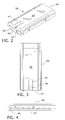
- Fig. 2 is a perspective view of the main body of a wedge with a wedge insert in place
- Fig. 3 is a top plan view of Fig. 2 ;
- Fig. 4 is a side plan view of Fig. 2 ;
- Fig. 5 is a perspective view of the remote controlled maintenance vehicle of this invention with the top cover shown removed;
- Fig. 6 is a sectional view of a portion of the remote controlled maintenance vehicle of Fig. 5 illustrating the telescoping members fully extended engaging a wedge;
- Fig. 7 is a sectional side view of a portion of the remote controlled maintenance vehicle of Fig. 5 illustrating the telescoping members and miniature piston drive mechanisms in their fully extended position;
- Fig. 8 is a sectional side view of the remote controlled maintenance vehicle of Fig. 5 illustrating the telescoping members in a 50% retracted position
- Fig. 9 is a side sectional view of a portion of the remote controlled maintenance vehicle of Fig. 5 showing the telescoping members and miniature piston drive mechanisms in a fully retracted position.
- Fig. 1 shows a partial cross-section of a generator rotor 52 and stator 48 with coil slots 51.
- a top coil 50 and bottom coil 49 is firmly situated in each of the coil slots 51 and, as will be described more fully hereafter, is held firmly in place by the wedge 38.
- the wedge 38 includes a main body 40 and insert 42 which cooperate together to firmly hold the wedge 38 within the dovetail 39 of the coil slot 51.
- the remote controlled dynamoelectric machine maintenance vehicle 10 of this invention is shown resting on the surface of the generator stator 48, flanked by its motorized track drive assemblies 30 and 32 within the air gap 54 between the generator stator 52 and the generator rotor 48.
- the maintenance vehicle of this invention 10 is shown centered over the main body 40 of a wedge 38 in position to tighten the wedge, as will explained more fully hereafter.
- the wedge 38 is more fully illustrated in Figs. 2, 3 and 4 .
- the peripheral cross-section of the main body 40 of the wedge 38 has a contour that matches the peripheral dovetail grooves 39 in the stator slot 51.
- the lower surface of the cavity 43 of the main body 40 is preferably tapered along its length so that when a corresponding taper on the upper surface of the insert at 42 is driven within the cavity, the height of the wedge 48 is increased, bringing pressure on the coils 49 and 50 to firmly seat the coils in the slot 51.
- the maintenance vehicle 10 of this invention has two latch pins for respectively securing the insert 42 and the main body 40 and driving the insert 42 inwardly within the cavity 43 of the main body 40 of the wedge 38.
- One of the latch pins engages a hole 46 within the insert 42 through a slot 41 in the main wedge body 40, while the other of the latch pins of the maintenance vehicle 10 is positioned against a backing pin contact area 44 on the other side of the main body 40 of the wedge 38.
- One or other of the latch pins are then driven towards the other to tighten the wedge within the coil slot 51.
- the basic drive carriage of the remote-controlled dynamoelectric machine maintenance vehicle 10 of this invention is generally described in U.S. Patent 6,889,783, issued May 10, 2005 to the assignee of this invention.
- the main carriage and drive train of the remote-controlled dynamoelectric machine 10 of this invention is basically shown in Fig. 5 .
- the vehicle 10 is a low clearance motorized vehicle that is comprised of a main body 28, two motorized track drive assemblies 30 and 32, and a "tail" section 20 which manages the electrical/hydraulic/pneumatic cables and is used as a handle for insertion and removal of the vehicle 10 in and out of the generator air gap 54.
- the vehicle 10 is shown and described as applied to a generator, it should be appreciated that it can be applied in any large dynamoelectric machine that employs wedges that can be tightened in place.
- the main body 28 houses two wedge compression pistons 12 and 14 which can be either hydraulic or pneumatic.
- the wedge compression pistons 12 and 14 have a 875" (2.22 cm) diameter bore. These pistons will extend and retract a forward drive pin assembly positioning the telescoping drive pin 36 over the hole 46 in the wedge 38 with the ability to exert up to 200 pounds of force to tighten the wedge 38.
- the drive pin assemblies can best be viewed from the side cross-sectional view shown in Fig. 6 .
- the main body of the remote controlled dynamoelectric machine maintenance vehicle 10 of this invention also incorporates two miniature pneumatic, spring return pistons 16 and 18.
- Each of the miniature pistons 16 and 18 is independently activated and mechanically linked to telescoping pin mechanisms 34 and 36, one of which is inserted into the tapered wedge insert hole 46 and the other is inserted at the backing pin contact area 44 at the other end of the main body of the wedge 38. Since the vehicle 10 will be used around the inside diameter of the stator 48, the main body 28 also has provisions for embedding eight rare-earth magnets 22 at various locations to assure adhesion at all points in the generator.
- the spring return action of the miniature pneumatic pistons 16 and 18 will act as a "fail safe” to remove the drive pins 34 and 36 from the wedge 38 if a pneumatic system failure should occur.
- Two remote video cameras 62 and 64 respectively located near the telescoping pins 36 and 34, are used to observe the positioning and insertion of the telescoping pins 34 and 36.
- Two "side car” track drives 30 and 32 located on either side of the main body 28, are mounted on pivoting mounts 66 and 68 to accommodate various diameter stators. These drives are motorized with variable speed motors 70 and 72.
- Rare-earth magnets 22 are embedded in the drive units to maintain contact in all areas of the generator.
- a forward-looking video camera 24 with lights 26 is mounted in the front of the main body 28, as shown in Fig. 5 .
- the tail section 20 of the vehicle 10 is used to house the umbilical cable containing the wiring and hoses to operate the unit. It is also used as an insertion/removal handle for placing the vehicle carriage 10 inside the generator.
- the telescoping drive pins 34 and 36 are mechanically linked to the miniature pneumatic pistons 16 and 18 by the mechanical linkage 58 that has a diagonal slot 60 that captures a pin 56 in the upper end of the telescoping pins 34 and 36.
- the pins 34 and 36 are retracted when the miniature pneumatic pistons 16 and 18 are de-energized and the linkage 58 is fully extended. This telescoping action is necessary, since the combined length of the pins 34 and 36 and the width of the main frame 28 at full pin insertion in the wedge 38, exceeds the clearance distance for the air gap 54 between the stator 48 and the generator rotor 52.
- the wedge tightening process proceeds as follows.
- the vehicle 10 of this invention will be driven into position using the video cameras 24, 62 and 64 to view the forward progress and pin 34 and 36 alignment with the wedge 38.
- the hydraulic wedge compression pistons 12 and 14 With the hydraulic wedge compression pistons 12 and 14 in the fully-extended position (the drive pin 36 positioned above the tapered wedge insert hole 46), viewing the fixed pin 34 via the video camera 64, the fixed pin 34 will latch to the back 44 of the tapered wedge 38.
- the hydraulic pistons 12 and 14 will be actuated, drawing the insertion pin 36 into position over the tapered wedge insert drive hole 46.
- Pneumatic piston 18 is then energized to insert the pin 36 into the hole 46.
- Regulated hydraulic pressure is then applied to the hydraulic wedge compression pistons until the proper force is achieved, tightening the wedge 38.
- the miniature pneumatic pistons 16 and 18 are then de-energized, retracting the pins 34 and 36, and the carriage 10 is driven to the next position.
- Fig. 7 more fully shows the position of the linkage 58 extending from the miniature pneumatic pistons 16 and 18 when the telescoping pins 34 and 36 are fully extended.
- Fig. 8 shows the position of the linkage 58 with the telescoping pins 50% retracted
- Fig. 9 shows the arrangement of the linkage 58 between the miniature pneumatic pistons and the telescoping pins with the telescoping pins 34 and 36 fully retracted.
Landscapes
- Engineering & Computer Science (AREA)
- Manufacturing & Machinery (AREA)
- Power Engineering (AREA)
- Manufacture Of Motors, Generators (AREA)
Abstract
Description
- The present invention relates to remote-controlled unmanned robotic vehicles. More specifically, the present invention relates to remote-controlled vehicles capable of movement within the air gap between a rotor and stator of a dynamoelectric machine to tighten wedges in the machine's stator slots.
- In dynamoelectric machines and, particularly in the stators of large dynamoelectric machines, it is conventional to build up an annular magnetic mass by stacking thin laminations of magnetic material on key bars. The laminations conventionally include slot-shaped openings therein which are aligned in the stacking process with corresponding openings in all other laminations to form a set of parallel slots in the inner surface of the annular magnetic mass. One or more conductors are placed in each slot to receive the generated electricity if the dynamoelectric machine is a generator or, to receive the driving electric power if the dynamoelectric machine is a motor. The conductors in the slots of a large dynamoelectric machine carry large currents and are subjected to large magnetic fields. They therefore experience very high forces tending to displace them within the slots. If steps are not taken to prevent such an occurrence, the forces acting on the conductors are sufficient to displace them in the slots and to damage or destroy the stator.
- In the power generation industry, hundreds of stator wedges are often used to assist in retaining the coils in the stator of a power generator or a motor. The wedges are positioned to overlie the coils. The stator wedges are positioned into wedge grooves or wedge slots formed in the peripheries of the core laminations within the coil slots. The laminations are conventionally formed of coated steel material. The stator wedges are conventionally formed of an epoxy-laminated glass material. Because the stator coil laminations are formed of a coated steel material, it is important that such wedges be formed of a non-conducting material so that a short is not created which can damage various portions of the generator. During use, the large magnetic forces generated by the rotor of a large dynamoelectric machine are sufficient to distort the cross section of the stator from circular to slightly elliptical. The major axis of the elliptical distortion rotates with the magnetic pulse of the rotor at a speed of, for example, 3,600 rpm. The stator slots are thereby cyclically widened and narrowed a very small amount at a frequency of 120Hz as the maxima and minima of the elliptical distortion travels there past twice per revolution of the rotor. With years of normal operation of such dynamoelectric machines, the stator wedges holding the stator coils can become loose. An undetected loose wedge condition can result in excessive vibration of the coils and eventually lead to a catastrophic failure of the machine. The typical assembly for a stator slot includes the stator coils, stator wedges, and wedge filler material. Normally, when wedges become loose, the generator rotor has to be removed, the loose wedges are removed and new wedges and filler material are installed. This is a time-consuming and expensive process.
- Stator wedges have been developed that can be tightened after they have been installed. This style wedge has a main body that is tapered on the underside to which a wedge insert (tapered to match the wedge) is slid beneath it. As the wedge insert is forced against the wedge in the taper of the wedge, it increases the thickness of the wedge assembly, thus compressing the slot contents and tightening the wedge in the wedge grooves or wedge slots referred to above, which are also referred to as the dovetail.
- It is an object of this invention to provide an apparatus that can tighten such wedges without removing the rotor.
- It is a further object of this invention to provide an apparatus that can tighten the stator wedges remotely.
- It is a further object of this invention to provide such apparatus that can tighten the stator wedges from within the air gap of a dynamoelectric machine remotely under the supervision of an operator.
- The present invention is a remote-controlled maintenance vehicle for tightening wedges in a generator coil slot that can travel and is operable within the air gap of a generator between the rotor and stator. Thus, employing the remote-controlled maintenance vehicle of this invention, generator wedges may be tightened without removing the rotor. While this invention is described in an application to generators, it should be appreciated that it can be applied equally as well to large motors.
- The maintenance vehicle of the present invention includes a frame and at least one drive module attached to the frame and having a drive train that utilizes magnetic adhesion to traverse an interior ferromagnetic surface of the dynamoelectric machine. A motor is operatively connected to the drive module and responsive to a signal from a remote controller to provide a motive force to the drive train. An effectuator is attached to the frame and is operable upon command from the remote controller to engage a wedge on the dynamoelectric machine and remotely tighten the wedge in a coil slot on the dynamoelectric machine. The dynamoelectric machine maintenance vehicle is sized and configured to fit between the stator and the rotor of the dynamoelectric machine. Preferably, the wedge comprises a main body and an insert configured so that movement of the insert relative to the main body in one direction increases the width of the wedge in the dynamoelectric machine slot and tightens the coil within the slot. The effectuator comprises a first and a second, spaced, telescoping member. The first telescoping member is operable, upon command, to extend from one side of the frame and engage the wedge insert. The second telescoping member is operable to extend from the one side of the frame and engage the main body of the wedge and at least one of the first and second telescoping members is operable to move in the one direction relative to the other of the first and second telescoping members and tighten the wedge in the slot.
- In one preferred embodiment, the telescoping members are pins that substantially fully retract within the frame when not fully extended. Desirably, the pins are operated by miniature pneumatic pistons to retract and extend from the frame. Preferably, the miniature pneumatic pistons are biased in the retracted position so that the first and second telescoping members are in a retracted position if pneumatic supply is disconnected from the pistons. In another embodiment, a camera assembly is provided for remotely viewing the engagement of the first telescoping member and/or the second telescoping member with the main body of the wedge and/or the insert of the wedge.
- In still another embodiment, the first telescoping member engages a hole in the insert to the wedge, and the second telescoping member engages a first end of the main body of the wedge that is opposite to a second end of the main body of the wedge into which the insert enters. Preferably, the wedge has an inclined, tapered surface where the insert contacts the main body of the wedge and desirably the main body of the wedge has a mating inclined, tapered surface where the insert contacts the main body of the wedge. A hydraulic or pneumatic cylinder and piston connected to either the first or second telescoping member moves either the first or second telescoping member in the one direction to increase the width of the wedge. Preferably, the other of the telescoping members is held in a stationary position while the insert is moved into the main body of the wedge. Desirably, the wedge insert has a hole that is engaged by either the first or second telescoping member and the main body of the wedge has a slot through which the hole in the insert can be engaged. When fully extended, the extended length of the telescoping member and width of the frame exceeds the clearance distance between the stator and rotor of the dynamoelectric machine.
- For a better understanding of the invention, reference may be made to the preferred embodiments exemplary of the invention, shown in the accompanying drawings in which:
-
Fig. 1 is a sectional view of a portion of a generator rotor and stator showing the coils in the stator slots anchored by a wedge and the remote controlled maintenance vehicle of this invention seated in the air gap on the stator over a wedge; -
Fig. 2 is a perspective view of the main body of a wedge with a wedge insert in place; -
Fig. 3 is a top plan view ofFig. 2 ; -
Fig. 4 is a side plan view ofFig. 2 ; -
Fig. 5 is a perspective view of the remote controlled maintenance vehicle of this invention with the top cover shown removed; -
Fig. 6 is a sectional view of a portion of the remote controlled maintenance vehicle ofFig. 5 illustrating the telescoping members fully extended engaging a wedge; -
Fig. 7 is a sectional side view of a portion of the remote controlled maintenance vehicle ofFig. 5 illustrating the telescoping members and miniature piston drive mechanisms in their fully extended position; -
Fig. 8 is a sectional side view of the remote controlled maintenance vehicle ofFig. 5 illustrating the telescoping members in a 50% retracted position; and -
Fig. 9 is a side sectional view of a portion of the remote controlled maintenance vehicle ofFig. 5 showing the telescoping members and miniature piston drive mechanisms in a fully retracted position. -
Fig. 1 shows a partial cross-section of agenerator rotor 52 andstator 48 withcoil slots 51. Atop coil 50 andbottom coil 49 is firmly situated in each of thecoil slots 51 and, as will be described more fully hereafter, is held firmly in place by thewedge 38. Thewedge 38 includes amain body 40 and insert 42 which cooperate together to firmly hold thewedge 38 within thedovetail 39 of thecoil slot 51. The remote controlled dynamoelectricmachine maintenance vehicle 10 of this invention is shown resting on the surface of thegenerator stator 48, flanked by its motorizedtrack drive assemblies air gap 54 between thegenerator stator 52 and thegenerator rotor 48. The maintenance vehicle of thisinvention 10 is shown centered over themain body 40 of awedge 38 in position to tighten the wedge, as will explained more fully hereafter. - The
wedge 38 is more fully illustrated inFigs. 2, 3 and 4 . The peripheral cross-section of themain body 40 of thewedge 38 has a contour that matches theperipheral dovetail grooves 39 in thestator slot 51. The lower surface of thecavity 43 of themain body 40 is preferably tapered along its length so that when a corresponding taper on the upper surface of the insert at 42 is driven within the cavity, the height of thewedge 48 is increased, bringing pressure on thecoils slot 51. As can best be seen fromFig. 4 , preferably the upper surface of theinsert 42 and the lower surface of thecavity 43 have matching tapers to maintain the upper surface of themain body 40 of thewedge 38 parallel with the lower surface of theinsert 42 to firmly seat thewedge 38 within thedovetail groove 39 of thecoil slot 51. As will be explained more fully hereafter, themaintenance vehicle 10 of this invention has two latch pins for respectively securing theinsert 42 and themain body 40 and driving theinsert 42 inwardly within thecavity 43 of themain body 40 of thewedge 38. One of the latch pins engages ahole 46 within theinsert 42 through aslot 41 in themain wedge body 40, while the other of the latch pins of themaintenance vehicle 10 is positioned against a backingpin contact area 44 on the other side of themain body 40 of thewedge 38. One or other of the latch pins are then driven towards the other to tighten the wedge within thecoil slot 51. - The basic drive carriage of the remote-controlled dynamoelectric
machine maintenance vehicle 10 of this invention is generally described inU.S. Patent 6,889,783, issued May 10, 2005 to the assignee of this invention. The main carriage and drive train of the remote-controlleddynamoelectric machine 10 of this invention is basically shown inFig. 5 . Thevehicle 10 is a low clearance motorized vehicle that is comprised of amain body 28, two motorizedtrack drive assemblies section 20 which manages the electrical/hydraulic/pneumatic cables and is used as a handle for insertion and removal of thevehicle 10 in and out of thegenerator air gap 54. Though thevehicle 10 is shown and described as applied to a generator, it should be appreciated that it can be applied in any large dynamoelectric machine that employs wedges that can be tightened in place. Themain body 28 houses two wedge compression pistons 12 and 14 which can be either hydraulic or pneumatic. In this example, the wedge compression pistons 12 and 14 have a 875" (2.22 cm) diameter bore. These pistons will extend and retract a forward drive pin assembly positioning thetelescoping drive pin 36 over thehole 46 in thewedge 38 with the ability to exert up to 200 pounds of force to tighten thewedge 38. The drive pin assemblies can best be viewed from the side cross-sectional view shown inFig. 6 . The main body of the remote controlled dynamoelectricmachine maintenance vehicle 10 of this invention also incorporates two miniature pneumatic,spring return pistons miniature pistons pin mechanisms wedge insert hole 46 and the other is inserted at the backingpin contact area 44 at the other end of the main body of thewedge 38. Since thevehicle 10 will be used around the inside diameter of thestator 48, themain body 28 also has provisions for embedding eight rare-earth magnets 22 at various locations to assure adhesion at all points in the generator. The spring return action of the miniaturepneumatic pistons wedge 38 if a pneumatic system failure should occur. Tworemote video cameras main body 28, are mounted on pivotingmounts variable speed motors earth magnets 22 are embedded in the drive units to maintain contact in all areas of the generator. A forward-lookingvideo camera 24 withlights 26 is mounted in the front of themain body 28, as shown inFig. 5 . - The
tail section 20 of thevehicle 10 is used to house the umbilical cable containing the wiring and hoses to operate the unit. It is also used as an insertion/removal handle for placing thevehicle carriage 10 inside the generator. - As can be best appreciated from
Figs. 6 ,7, 8 and 9 , the telescoping drive pins 34 and 36 are mechanically linked to the miniaturepneumatic pistons mechanical linkage 58 that has adiagonal slot 60 that captures apin 56 in the upper end of the telescoping pins 34 and 36. Thepins pneumatic pistons linkage 58 is fully extended. This telescoping action is necessary, since the combined length of thepins main frame 28 at full pin insertion in thewedge 38, exceeds the clearance distance for theair gap 54 between thestator 48 and thegenerator rotor 52. - The wedge tightening process proceeds as follows. The
vehicle 10 of this invention will be driven into position using thevideo cameras pin wedge 38. With the hydraulic wedge compression pistons 12 and 14 in the fully-extended position (thedrive pin 36 positioned above the tapered wedge insert hole 46), viewing the fixedpin 34 via thevideo camera 64, the fixedpin 34 will latch to theback 44 of the taperedwedge 38. Then, while viewing theinsertion pin camera 62, the hydraulic pistons 12 and 14 will be actuated, drawing theinsertion pin 36 into position over the tapered wedgeinsert drive hole 46.Pneumatic piston 18 is then energized to insert thepin 36 into thehole 46. Regulated hydraulic pressure is then applied to the hydraulic wedge compression pistons until the proper force is achieved, tightening thewedge 38. The miniaturepneumatic pistons pins carriage 10 is driven to the next position. -
Fig. 7 more fully shows the position of thelinkage 58 extending from the miniaturepneumatic pistons Fig. 8 shows the position of thelinkage 58 with the telescoping pins 50% retracted, andFig. 9 shows the arrangement of thelinkage 58 between the miniature pneumatic pistons and the telescoping pins with the telescoping pins 34 and 36 fully retracted. - Thus, by using this remotely-controlled "low clearance"
style carriage 10, the need to remove therotor 52 for wedge tightening is eliminated. Thus, down time for the generator can be greatly reduced. - While specific embodiments of the invention have been described in detail, it will be appreciated by those skilled in the art that various modifications and alternatives to those details could be developed in light of the overall teachings of the disclosure. Accordingly, the particular embodiments disclosed are meant to be illustrative only and not limiting as to the scope of the invention which is to be given the full breadth of the appended claims and any and all equivalents thereof.
Claims (16)
- A remote-controlled dynamoelectric machine maintenance vehicle (10), comprising:a frame (28);at least one drive module (32) attached to the frame and having a drive train that utilizes magnetic adhesion (22) to traverse an interior ferromagnetic surface of the dynamoelectric machine;a motor (70) operatively connected to the drive module and responsive to a signal from a remote-controller, the motor providing a motive force to the drive train;an effectuator (16, 18) attached to the frame and operable to engage a wedge (38) on the dynamoelectric machine and remotely tighten the wedge in a dynamoelectric machine slot (51); andwherein the dynamoelectric machine maintenance vehicle is sized and configured to fit between a stator (48) of the dynamoelectric machine and rotor (52) of the dynamoelectric machine.
- The remote-controlled dynamoelectric machine maintenance vehicle (10) of Claim 1 wherein the wedge (38) comprises a main body (40) and an insert (42) wherein movement of the insert relative to the main body in one direction increases the width of the wedge in the dynamoelectric machine slot and tightens a coil within the slot and the effectuator (16, 18) comprises a first and a second, spaced, telescoping members (34, 36), the first, telescoping member (36) operable, upon command, to extend from one side of the frame and engage the wedge insert (42) and the second, telescoping member (34) operable to extend from the one side of the frame and engage the main body (40) of the wedge (38) and at least one of the first and second telescoping members operable to move in the one direction relative to the other of the first and second telescoping members and tighten the wedge in the slot (51).
- The remote-controlled dynamoelectric machine maintenance vehicle (10) of Claim 2 wherein the first and second telescoping members (34, 36) are pins that substantially fully retract into the frame (28) when not extended.
- The remote-controlled dynamoelectric machine maintenance vehicle (10) of Claim 2 wherein the first and second telescoping members (34, 36) are piston operated to retract and extend from the frame (28).
- The remote-controlled dynamoelectric machine maintenance vehicle (10) of Claim 4 wherein the pistons (16, 18) are biased in the retracted position so that the first and second telescoping members (34, 36) are in a retracted position if a corresponding energy supply is disconnected from the pistons.
- The remote-controlled dynamoelectric machine maintenance vehicle (10) of Claim 2 including a camera assembly (62, 64) for remotely viewing the engagement of the first telescoping member (34) or the second telescoping member (36) with the main body (40) of the wedge (38) or the insert (42) of the wedge.
- The remote-controlled dynamoelectric machine maintenance vehicle (10) of Claim 6 wherein the camera assembly (62, 64) views the engagement of the first and second telescoping members (34, 36) with the main body (40) and the insert (42) of the wedge (38).
- The remote-controlled dynamoelectric machine maintenance vehicle (10) of Claim 2 wherein the first telescoping member (36) engages a hole (46) in the insert (42) to the wedge (38) and the second telescoping member (34) engages a first end (44) of the main body (40) of the wedge (38) that is opposite a second end of the main body of the wedge into which the insert enters.
- The remote-controlled dynamoelectric machine maintenance vehicle (10) of Claim 2 wherein at least one of the insert (42) or the main body (40) of the wedge (38) has an inclined, tapered surface where the insert contacts the main body of the wedge.
- The remote-controlled dynamoelectric machine maintenance vehicle (10) of Claim 9 wherein both the insert (42) and the main body (40) of the wedge (38) have inclined, tapered surfaces where the insert contacts the main body of the wedge.
- The remote-controlled dynamoelectric machine maintenance vehicle (10) of Claim 2 including a hydraulic or pneumatic cylinder and piston (16, 18) connected to either the first or second telescoping member (34, 36) for moving either the first or second telescoping member in the one direction.
- The remote-controlled dynamoelectric machine maintenance vehicle (10) of Claim 2 wherein one of the first or second telescoping members (34, 36) is held in a stationary position while the other of the first and second telescoping members are moved in the one direction.
- The remote-controlled dynamoelectric machine maintenance vehicle (10) of Claim 1 including a forward looking video camera (24) mounted in the front of the frame (28).
- The remote-controlled dynamoelectric machine maintenance vehicle (10) of Claim 13 wherein the forward looking video camera (24) includes lights (26).
- The remote-controlled dynamoelectric machine maintenance vehicle (10) of Claim 2 wherein the length of the first and second telescoping members (34, 36) when fully extended exceeds the clearance distance between a stator (48) and a rotor (52) of the dynamoelectric machine.
- The remote-controlled dynamoelectric machine maintenance vehicle (10) of Claim 2 wherein the wedge insert (42) has a hole (46) that is engaged by either the first or the second telescoping member (34, 36) and the main body (40) of the wedge (38) has a slot (41) through which the hole in the insert can be engaged by either the first or the second telescoping member.
Applications Claiming Priority (1)
| Application Number | Priority Date | Filing Date | Title |
|---|---|---|---|
| US12/020,780 US7866421B2 (en) | 2008-01-28 | 2008-01-28 | Automated remote carriage for tightening generator wedges |
Publications (2)
| Publication Number | Publication Date |
|---|---|
| EP2096738A1 true EP2096738A1 (en) | 2009-09-02 |
| EP2096738B1 EP2096738B1 (en) | 2016-05-18 |
Family
ID=40810523
Family Applications (1)
| Application Number | Title | Priority Date | Filing Date |
|---|---|---|---|
| EP09150429.0A Active EP2096738B1 (en) | 2008-01-28 | 2009-01-13 | Automated remote carriage for tightening generator wedges |
Country Status (3)
| Country | Link |
|---|---|
| US (1) | US7866421B2 (en) |
| EP (1) | EP2096738B1 (en) |
| ES (1) | ES2587388T3 (en) |
Cited By (7)
| Publication number | Priority date | Publication date | Assignee | Title |
|---|---|---|---|---|
| EP2690755A1 (en) * | 2012-07-27 | 2014-01-29 | Siemens Aktiengesellschaft | Machine and inspection device for a machine |
| WO2015095543A1 (en) * | 2013-12-18 | 2015-06-25 | Abb Technology Ag | Modular confined space crawler for use in machinery |
| EP3262429A4 (en) * | 2015-02-27 | 2018-10-31 | ABB Schweiz AG | Localization, mapping and haptic feedback for inspection of a confined space in machinery |
| US20190173347A1 (en) * | 2017-12-05 | 2019-06-06 | Siemens Energy, Inc. | Tool system for tightening retightenable wedge system in slot of generator stator core |
| DE102019207248A1 (en) * | 2019-05-17 | 2020-11-19 | Siemens Aktiengesellschaft | Test vehicle |
| DE102020203559A1 (en) | 2020-03-19 | 2021-09-23 | Siemens Aktiengesellschaft | Test vehicle |
| CN113997309A (en) * | 2021-12-31 | 2022-02-01 | 湖南大学 | A wall-climbing generator maintenance robot device based on swing mechanism |
Families Citing this family (21)
| Publication number | Priority date | Publication date | Assignee | Title |
|---|---|---|---|---|
| US10427290B2 (en) | 2017-07-18 | 2019-10-01 | General Electric Company | Crawler robot for in situ gap inspection |
| US9254898B2 (en) * | 2008-11-21 | 2016-02-09 | Raytheon Company | Hull robot with rotatable turret |
| US8342281B2 (en) * | 2008-11-21 | 2013-01-01 | Raytheon Company | Hull robot steering system |
| US9440717B2 (en) * | 2008-11-21 | 2016-09-13 | Raytheon Company | Hull robot |
| US8393286B2 (en) * | 2009-09-18 | 2013-03-12 | Raytheon Company | Hull robot garage |
| US8393421B2 (en) * | 2009-10-14 | 2013-03-12 | Raytheon Company | Hull robot drive system |
| US8386112B2 (en) | 2010-05-17 | 2013-02-26 | Raytheon Company | Vessel hull robot navigation subsystem |
| US9051028B2 (en) | 2012-09-14 | 2015-06-09 | Raytheon Company | Autonomous hull inspection |
| US9428231B2 (en) * | 2013-02-13 | 2016-08-30 | James Walter Beard | Climbing vehicle with suspension mechanism |
| USD756922S1 (en) * | 2014-02-03 | 2016-05-24 | Abb Technology Ag | Rotating electrical machinery modular air gap crawler |
| USD748053S1 (en) * | 2014-02-03 | 2016-01-26 | Abb Technology Ag | Rotating electrical machinery modular air gap crawler |
| US10224776B2 (en) | 2015-06-03 | 2019-03-05 | General Electric Company | Retention assembly for stator bar using shim with stator wedge and related method |
| US10197538B2 (en) | 2016-02-02 | 2019-02-05 | Siemens Energy, Inc. | Systems and apparatus for inspection of electric generator rotor slot wedges in-situ and methods of using the same |
| US10603802B2 (en) | 2017-07-18 | 2020-03-31 | General Electric Company | End region inspection module and method for in situ gap inspection robot system |
| US10596713B2 (en) | 2017-07-18 | 2020-03-24 | General Electric Company | Actuated sensor module and method for in situ gap inspection robots |
| US10434641B2 (en) | 2017-07-18 | 2019-10-08 | General Electric Company | In situ gap inspection robot system and method |
| US10427734B2 (en) | 2017-07-18 | 2019-10-01 | General Electric Company | Omnidirectional traction module for a robot |
| EP3971565B8 (en) * | 2019-06-14 | 2024-11-06 | Mitsubishi Generator Co., Ltd. | Device for inspecting wedge looseness of rotary electric machine, system for inspecting wedge looseness of rotary electric machine, and method for inspecting wedge looseness of rotary electric machine |
| EP4018210B1 (en) | 2019-08-20 | 2026-01-14 | GE Vernova Technology GmbH | Visual inspection module with dual view paths for robot |
| CN114761312B (en) | 2019-08-20 | 2024-11-26 | 通用电气技术有限公司 | Traction module of a robot with variable extension position |
| CN117698866B (en) * | 2023-11-17 | 2024-08-13 | 华电电力科学研究院有限公司 | Wall climbing robot for detecting faults in generator set chamber |
Citations (3)
| Publication number | Priority date | Publication date | Assignee | Title |
|---|---|---|---|---|
| US5248008A (en) * | 1989-08-31 | 1993-09-28 | Framatome | Self-traveling robotic vehicle with inclinable propulsion units |
| US20020104693A1 (en) | 2000-11-28 | 2002-08-08 | Siemens Westinghouse Power Corporation | Remote controlled inspection vehicle utilizing magnetic adhesion to traverse nonhorizontal, nonflat, ferromagnetic surfaces |
| EP1772949A1 (en) * | 2005-10-10 | 2007-04-11 | General Electric Company | Ultrasonic miniature air gap inspection crawler |
Family Cites Families (9)
| Publication number | Priority date | Publication date | Assignee | Title |
|---|---|---|---|---|
| JPS5179497A (en) * | 1974-12-28 | 1976-07-10 | Sanko Co Inc | |
| US4200818A (en) | 1978-08-01 | 1980-04-29 | Westinghouse Electric Corp. | Resin impregnated aromatic polyamide covered glass based slot wedge for large dynamoelectric machines |
| US4607183A (en) | 1984-11-14 | 1986-08-19 | General Electric Company | Dynamoelectric machine slot wedges with abrasion resistant layer |
| US4934475A (en) * | 1987-04-04 | 1990-06-19 | Uragami Fukashi | Device capable of suction-adhering to a wall surface and moving therealong |
| US6124659A (en) | 1999-08-20 | 2000-09-26 | Siemens Westinghouse Power Corporation | Stator wedge having abrasion-resistant edge and methods of forming same |
| US6653759B1 (en) | 2000-09-20 | 2003-11-25 | Siemens Westinghouse Power Corporation | Coil support finger plate for stator of power generator and associated methods |
| US6964312B2 (en) * | 2003-10-07 | 2005-11-15 | International Climbing Machines, Inc. | Surface traversing apparatus and method |
| US20080078599A1 (en) * | 2006-09-29 | 2008-04-03 | Honeywell International Inc. | Vehicle and method for inspecting a space |
| US7654348B2 (en) * | 2006-10-06 | 2010-02-02 | Irobot Corporation | Maneuvering robotic vehicles having a positionable sensor head |
-
2008
- 2008-01-28 US US12/020,780 patent/US7866421B2/en active Active
-
2009
- 2009-01-13 ES ES09150429.0T patent/ES2587388T3/en active Active
- 2009-01-13 EP EP09150429.0A patent/EP2096738B1/en active Active
Patent Citations (4)
| Publication number | Priority date | Publication date | Assignee | Title |
|---|---|---|---|---|
| US5248008A (en) * | 1989-08-31 | 1993-09-28 | Framatome | Self-traveling robotic vehicle with inclinable propulsion units |
| US20020104693A1 (en) | 2000-11-28 | 2002-08-08 | Siemens Westinghouse Power Corporation | Remote controlled inspection vehicle utilizing magnetic adhesion to traverse nonhorizontal, nonflat, ferromagnetic surfaces |
| US6889783B1 (en) | 2000-11-28 | 2005-05-10 | Siemens Westinghouse Power Corporation | Remote controlled inspection vehicle utilizing magnetic adhesion to traverse nonhorizontal, nonflat, ferromagnetic surfaces |
| EP1772949A1 (en) * | 2005-10-10 | 2007-04-11 | General Electric Company | Ultrasonic miniature air gap inspection crawler |
Cited By (15)
| Publication number | Priority date | Publication date | Assignee | Title |
|---|---|---|---|---|
| EP2690755A1 (en) * | 2012-07-27 | 2014-01-29 | Siemens Aktiengesellschaft | Machine and inspection device for a machine |
| WO2014016052A3 (en) * | 2012-07-27 | 2014-12-18 | Siemens Aktiengesellschaft | Inspection device for a machine |
| US9866090B2 (en) | 2012-07-27 | 2018-01-09 | Siemens Aktiegesellschaft | Inspection device for a machine |
| WO2015095543A1 (en) * | 2013-12-18 | 2015-06-25 | Abb Technology Ag | Modular confined space crawler for use in machinery |
| EP3262429A4 (en) * | 2015-02-27 | 2018-10-31 | ABB Schweiz AG | Localization, mapping and haptic feedback for inspection of a confined space in machinery |
| US10712391B2 (en) | 2015-02-27 | 2020-07-14 | Abb Schweiz Ag | Localization, mapping and haptic feedback for inspection of a confined space in machinery |
| WO2019112783A3 (en) * | 2017-12-05 | 2019-08-29 | Siemens Energy, Inc. | Tool system for tightening retightenable wedge system in slot of generator stator core |
| US20190173347A1 (en) * | 2017-12-05 | 2019-06-06 | Siemens Energy, Inc. | Tool system for tightening retightenable wedge system in slot of generator stator core |
| KR20200095515A (en) * | 2017-12-05 | 2020-08-10 | 지멘스 에너지, 인코포레이티드 | Tool system for tightening the retightenable wedge system in the slot of the generator stator core |
| US10797552B2 (en) | 2017-12-05 | 2020-10-06 | Siemens Energy, Inc. | Tool system for tightening retightenable wedge system in slot of generator stator core |
| DE102019207248A1 (en) * | 2019-05-17 | 2020-11-19 | Siemens Aktiengesellschaft | Test vehicle |
| US12015839B2 (en) | 2019-05-17 | 2024-06-18 | Siemens Energy Global GmbH & Co. KG | Inspection vehicle |
| DE102020203559A1 (en) | 2020-03-19 | 2021-09-23 | Siemens Aktiengesellschaft | Test vehicle |
| CN113997309A (en) * | 2021-12-31 | 2022-02-01 | 湖南大学 | A wall-climbing generator maintenance robot device based on swing mechanism |
| CN113997309B (en) * | 2021-12-31 | 2022-04-05 | 湖南大学 | A wall-climbing generator maintenance robot device based on swing mechanism |
Also Published As
| Publication number | Publication date |
|---|---|
| EP2096738B1 (en) | 2016-05-18 |
| US20090194346A1 (en) | 2009-08-06 |
| ES2587388T3 (en) | 2016-10-24 |
| US7866421B2 (en) | 2011-01-11 |
Similar Documents
| Publication | Publication Date | Title |
|---|---|---|
| EP2096738B1 (en) | Automated remote carriage for tightening generator wedges | |
| EP2494682B1 (en) | Magnet assembly | |
| US9071116B2 (en) | Apparatus for installing stator winding conductors | |
| US9759667B2 (en) | Miniature air gap inspection crawler | |
| US4281264A (en) | Mounting of armature conductors in air-gap armatures | |
| US20120233848A1 (en) | Rotary table for permanent magnet rotating machine and method for manufacturing permanent magnet rotating machine | |
| WO2011010281A1 (en) | Electric device stator and methods for winding | |
| JPH04229037A (en) | Tool and support for attaching and detaching coil slot wedge of generator rotor | |
| EP3160022A1 (en) | Combined stator wedge driver and bar jacking tool | |
| US5027500A (en) | Generator rotor slot wedge assembly and disassembly | |
| CN1093993C (en) | Slot-wedge pressing device for rotating motor | |
| US8125114B2 (en) | Dynamoelectric machine locking wedge for maintaining a winding in a slot | |
| EP3156150B1 (en) | Stacker and method for stacking a stator core of an electric machine | |
| JP2009219283A (en) | Motor assembling apparatus and motor assembling method | |
| CN113711475A (en) | Drive motor with balancing section at rotor | |
| US10797552B2 (en) | Tool system for tightening retightenable wedge system in slot of generator stator core | |
| US7990012B2 (en) | Locking wedge for maintaining a winding in a slot and dynamoelectric machine incorporating same | |
| US8959736B2 (en) | System and method for inserting ripple springs | |
| US5517750A (en) | Apparatus for salvaging core laminations | |
| US5048177A (en) | Generator rotor slot wedge tool | |
| CN223978562U (en) | Rail mounted generator rotor wears to install equipment | |
| CN102916503B (en) | Pole locking device | |
| CN211429152U (en) | Permanent magnet motor general assembly professional equipment | |
| KR100302404B1 (en) | Method for Assembling Coil Moving Type Linear Motor | |
| CN121924716A (en) | Mining flame proof safety control case of lightweight based on bionic structure |
Legal Events
| Date | Code | Title | Description |
|---|---|---|---|
| PUAI | Public reference made under article 153(3) epc to a published international application that has entered the european phase |
Free format text: ORIGINAL CODE: 0009012 |
|
| AK | Designated contracting states |
Kind code of ref document: A1 Designated state(s): AT BE BG CH CY CZ DE DK EE ES FI FR GB GR HR HU IE IS IT LI LT LU LV MC MK MT NL NO PL PT RO SE SI SK TR |
|
| AX | Request for extension of the european patent |
Extension state: AL BA RS |
|
| 17P | Request for examination filed |
Effective date: 20100118 |
|
| 17Q | First examination report despatched |
Effective date: 20100211 |
|
| AKX | Designation fees paid |
Designated state(s): AT BE BG CH CY CZ DE DK EE ES FI FR GB GR HR HU IE IS IT LI LT LU LV MC MK MT NL NO PL PT RO SE SI SK TR |
|
| GRAP | Despatch of communication of intention to grant a patent |
Free format text: ORIGINAL CODE: EPIDOSNIGR1 |
|
| INTG | Intention to grant announced |
Effective date: 20151215 |
|
| GRAS | Grant fee paid |
Free format text: ORIGINAL CODE: EPIDOSNIGR3 |
|
| GRAA | (expected) grant |
Free format text: ORIGINAL CODE: 0009210 |
|
| AK | Designated contracting states |
Kind code of ref document: B1 Designated state(s): AT BE BG CH CY CZ DE DK EE ES FI FR GB GR HR HU IE IS IT LI LT LU LV MC MK MT NL NO PL PT RO SE SI SK TR |
|
| REG | Reference to a national code |
Ref country code: GB Ref legal event code: FG4D |
|
| REG | Reference to a national code |
Ref country code: CH Ref legal event code: EP Ref country code: CH Ref legal event code: NV Representative=s name: SIEMENS SCHWEIZ AG, CH |
|
| REG | Reference to a national code |
Ref country code: IE Ref legal event code: FG4D Ref country code: AT Ref legal event code: REF Ref document number: 801222 Country of ref document: AT Kind code of ref document: T Effective date: 20160615 |
|
| REG | Reference to a national code |
Ref country code: DE Ref legal event code: R096 Ref document number: 602009038689 Country of ref document: DE |
|
| REG | Reference to a national code |
Ref country code: NL Ref legal event code: MP Effective date: 20160518 |
|
| REG | Reference to a national code |
Ref country code: LT Ref legal event code: MG4D |
|
| REG | Reference to a national code |
Ref country code: ES Ref legal event code: FG2A Ref document number: 2587388 Country of ref document: ES Kind code of ref document: T3 Effective date: 20161024 |
|
| PG25 | Lapsed in a contracting state [announced via postgrant information from national office to epo] |
Ref country code: FI Free format text: LAPSE BECAUSE OF FAILURE TO SUBMIT A TRANSLATION OF THE DESCRIPTION OR TO PAY THE FEE WITHIN THE PRESCRIBED TIME-LIMIT Effective date: 20160518 Ref country code: NL Free format text: LAPSE BECAUSE OF FAILURE TO SUBMIT A TRANSLATION OF THE DESCRIPTION OR TO PAY THE FEE WITHIN THE PRESCRIBED TIME-LIMIT Effective date: 20160518 Ref country code: LT Free format text: LAPSE BECAUSE OF FAILURE TO SUBMIT A TRANSLATION OF THE DESCRIPTION OR TO PAY THE FEE WITHIN THE PRESCRIBED TIME-LIMIT Effective date: 20160518 Ref country code: NO Free format text: LAPSE BECAUSE OF FAILURE TO SUBMIT A TRANSLATION OF THE DESCRIPTION OR TO PAY THE FEE WITHIN THE PRESCRIBED TIME-LIMIT Effective date: 20160818 |
|
| REG | Reference to a national code |
Ref country code: AT Ref legal event code: MK05 Ref document number: 801222 Country of ref document: AT Kind code of ref document: T Effective date: 20160518 |
|
| PG25 | Lapsed in a contracting state [announced via postgrant information from national office to epo] |
Ref country code: HR Free format text: LAPSE BECAUSE OF FAILURE TO SUBMIT A TRANSLATION OF THE DESCRIPTION OR TO PAY THE FEE WITHIN THE PRESCRIBED TIME-LIMIT Effective date: 20160518 Ref country code: GR Free format text: LAPSE BECAUSE OF FAILURE TO SUBMIT A TRANSLATION OF THE DESCRIPTION OR TO PAY THE FEE WITHIN THE PRESCRIBED TIME-LIMIT Effective date: 20160819 Ref country code: LV Free format text: LAPSE BECAUSE OF FAILURE TO SUBMIT A TRANSLATION OF THE DESCRIPTION OR TO PAY THE FEE WITHIN THE PRESCRIBED TIME-LIMIT Effective date: 20160518 Ref country code: PT Free format text: LAPSE BECAUSE OF FAILURE TO SUBMIT A TRANSLATION OF THE DESCRIPTION OR TO PAY THE FEE WITHIN THE PRESCRIBED TIME-LIMIT Effective date: 20160919 Ref country code: SE Free format text: LAPSE BECAUSE OF FAILURE TO SUBMIT A TRANSLATION OF THE DESCRIPTION OR TO PAY THE FEE WITHIN THE PRESCRIBED TIME-LIMIT Effective date: 20160518 |
|
| REG | Reference to a national code |
Ref country code: FR Ref legal event code: PLFP Year of fee payment: 9 |
|
| PG25 | Lapsed in a contracting state [announced via postgrant information from national office to epo] |
Ref country code: DK Free format text: LAPSE BECAUSE OF FAILURE TO SUBMIT A TRANSLATION OF THE DESCRIPTION OR TO PAY THE FEE WITHIN THE PRESCRIBED TIME-LIMIT Effective date: 20160518 Ref country code: EE Free format text: LAPSE BECAUSE OF FAILURE TO SUBMIT A TRANSLATION OF THE DESCRIPTION OR TO PAY THE FEE WITHIN THE PRESCRIBED TIME-LIMIT Effective date: 20160518 Ref country code: RO Free format text: LAPSE BECAUSE OF FAILURE TO SUBMIT A TRANSLATION OF THE DESCRIPTION OR TO PAY THE FEE WITHIN THE PRESCRIBED TIME-LIMIT Effective date: 20160518 Ref country code: CZ Free format text: LAPSE BECAUSE OF FAILURE TO SUBMIT A TRANSLATION OF THE DESCRIPTION OR TO PAY THE FEE WITHIN THE PRESCRIBED TIME-LIMIT Effective date: 20160518 Ref country code: SK Free format text: LAPSE BECAUSE OF FAILURE TO SUBMIT A TRANSLATION OF THE DESCRIPTION OR TO PAY THE FEE WITHIN THE PRESCRIBED TIME-LIMIT Effective date: 20160518 |
|
| REG | Reference to a national code |
Ref country code: DE Ref legal event code: R097 Ref document number: 602009038689 Country of ref document: DE |
|
| PG25 | Lapsed in a contracting state [announced via postgrant information from national office to epo] |
Ref country code: BE Free format text: LAPSE BECAUSE OF FAILURE TO SUBMIT A TRANSLATION OF THE DESCRIPTION OR TO PAY THE FEE WITHIN THE PRESCRIBED TIME-LIMIT Effective date: 20160518 Ref country code: AT Free format text: LAPSE BECAUSE OF FAILURE TO SUBMIT A TRANSLATION OF THE DESCRIPTION OR TO PAY THE FEE WITHIN THE PRESCRIBED TIME-LIMIT Effective date: 20160518 Ref country code: PL Free format text: LAPSE BECAUSE OF FAILURE TO SUBMIT A TRANSLATION OF THE DESCRIPTION OR TO PAY THE FEE WITHIN THE PRESCRIBED TIME-LIMIT Effective date: 20160518 |
|
| PLBE | No opposition filed within time limit |
Free format text: ORIGINAL CODE: 0009261 |
|
| STAA | Information on the status of an ep patent application or granted ep patent |
Free format text: STATUS: NO OPPOSITION FILED WITHIN TIME LIMIT |
|
| 26N | No opposition filed |
Effective date: 20170221 |
|
| PG25 | Lapsed in a contracting state [announced via postgrant information from national office to epo] |
Ref country code: SI Free format text: LAPSE BECAUSE OF FAILURE TO SUBMIT A TRANSLATION OF THE DESCRIPTION OR TO PAY THE FEE WITHIN THE PRESCRIBED TIME-LIMIT Effective date: 20160518 |
|
| PG25 | Lapsed in a contracting state [announced via postgrant information from national office to epo] |
Ref country code: MC Free format text: LAPSE BECAUSE OF FAILURE TO SUBMIT A TRANSLATION OF THE DESCRIPTION OR TO PAY THE FEE WITHIN THE PRESCRIBED TIME-LIMIT Effective date: 20160518 |
|
| REG | Reference to a national code |
Ref country code: IE Ref legal event code: MM4A |
|
| PG25 | Lapsed in a contracting state [announced via postgrant information from national office to epo] |
Ref country code: LU Free format text: LAPSE BECAUSE OF NON-PAYMENT OF DUE FEES Effective date: 20170113 |
|
| REG | Reference to a national code |
Ref country code: FR Ref legal event code: PLFP Year of fee payment: 10 |
|
| PG25 | Lapsed in a contracting state [announced via postgrant information from national office to epo] |
Ref country code: IE Free format text: LAPSE BECAUSE OF NON-PAYMENT OF DUE FEES Effective date: 20170113 |
|
| PG25 | Lapsed in a contracting state [announced via postgrant information from national office to epo] |
Ref country code: MT Free format text: LAPSE BECAUSE OF NON-PAYMENT OF DUE FEES Effective date: 20170113 |
|
| PGFP | Annual fee paid to national office [announced via postgrant information from national office to epo] |
Ref country code: FR Payment date: 20190320 Year of fee payment: 10 Ref country code: GB Payment date: 20190117 Year of fee payment: 11 Ref country code: IT Payment date: 20190130 Year of fee payment: 11 |
|
| PG25 | Lapsed in a contracting state [announced via postgrant information from national office to epo] |
Ref country code: HU Free format text: LAPSE BECAUSE OF FAILURE TO SUBMIT A TRANSLATION OF THE DESCRIPTION OR TO PAY THE FEE WITHIN THE PRESCRIBED TIME-LIMIT; INVALID AB INITIO Effective date: 20090113 |
|
| PGFP | Annual fee paid to national office [announced via postgrant information from national office to epo] |
Ref country code: ES Payment date: 20190422 Year of fee payment: 11 |
|
| PG25 | Lapsed in a contracting state [announced via postgrant information from national office to epo] |
Ref country code: BG Free format text: LAPSE BECAUSE OF FAILURE TO SUBMIT A TRANSLATION OF THE DESCRIPTION OR TO PAY THE FEE WITHIN THE PRESCRIBED TIME-LIMIT Effective date: 20160518 |
|
| PGFP | Annual fee paid to national office [announced via postgrant information from national office to epo] |
Ref country code: CH Payment date: 20190402 Year of fee payment: 11 |
|
| PG25 | Lapsed in a contracting state [announced via postgrant information from national office to epo] |
Ref country code: CY Free format text: LAPSE BECAUSE OF NON-PAYMENT OF DUE FEES Effective date: 20160518 |
|
| PG25 | Lapsed in a contracting state [announced via postgrant information from national office to epo] |
Ref country code: MK Free format text: LAPSE BECAUSE OF FAILURE TO SUBMIT A TRANSLATION OF THE DESCRIPTION OR TO PAY THE FEE WITHIN THE PRESCRIBED TIME-LIMIT Effective date: 20160518 |
|
| PG25 | Lapsed in a contracting state [announced via postgrant information from national office to epo] |
Ref country code: TR Free format text: LAPSE BECAUSE OF FAILURE TO SUBMIT A TRANSLATION OF THE DESCRIPTION OR TO PAY THE FEE WITHIN THE PRESCRIBED TIME-LIMIT Effective date: 20160518 |
|
| PG25 | Lapsed in a contracting state [announced via postgrant information from national office to epo] |
Ref country code: IS Free format text: LAPSE BECAUSE OF FAILURE TO SUBMIT A TRANSLATION OF THE DESCRIPTION OR TO PAY THE FEE WITHIN THE PRESCRIBED TIME-LIMIT Effective date: 20160918 |
|
| REG | Reference to a national code |
Ref country code: CH Ref legal event code: PL |
|
| GBPC | Gb: european patent ceased through non-payment of renewal fee |
Effective date: 20200113 |
|
| PG25 | Lapsed in a contracting state [announced via postgrant information from national office to epo] |
Ref country code: GB Free format text: LAPSE BECAUSE OF NON-PAYMENT OF DUE FEES Effective date: 20200113 Ref country code: FR Free format text: LAPSE BECAUSE OF NON-PAYMENT OF DUE FEES Effective date: 20200131 |
|
| PG25 | Lapsed in a contracting state [announced via postgrant information from national office to epo] |
Ref country code: LI Free format text: LAPSE BECAUSE OF NON-PAYMENT OF DUE FEES Effective date: 20200131 Ref country code: CH Free format text: LAPSE BECAUSE OF NON-PAYMENT OF DUE FEES Effective date: 20200131 |
|
| PG25 | Lapsed in a contracting state [announced via postgrant information from national office to epo] |
Ref country code: IT Free format text: LAPSE BECAUSE OF NON-PAYMENT OF DUE FEES Effective date: 20200113 |
|
| REG | Reference to a national code |
Ref country code: ES Ref legal event code: FD2A Effective date: 20210603 |
|
| PG25 | Lapsed in a contracting state [announced via postgrant information from national office to epo] |
Ref country code: ES Free format text: LAPSE BECAUSE OF NON-PAYMENT OF DUE FEES Effective date: 20200114 |
|
| REG | Reference to a national code |
Ref country code: DE Ref legal event code: R082 Ref document number: 602009038689 Country of ref document: DE Representative=s name: ROTH, THOMAS, DIPL.-PHYS. DR., DE |
|
| P01 | Opt-out of the competence of the unified patent court (upc) registered |
Effective date: 20231221 |
|
| PGFP | Annual fee paid to national office [announced via postgrant information from national office to epo] |
Ref country code: DE Payment date: 20260127 Year of fee payment: 18 |