EP2096457A2 - Digital beam forming using frequency-modulated signals - Google Patents
Digital beam forming using frequency-modulated signals Download PDFInfo
- Publication number
- EP2096457A2 EP2096457A2 EP09002786A EP09002786A EP2096457A2 EP 2096457 A2 EP2096457 A2 EP 2096457A2 EP 09002786 A EP09002786 A EP 09002786A EP 09002786 A EP09002786 A EP 09002786A EP 2096457 A2 EP2096457 A2 EP 2096457A2
- Authority
- EP
- European Patent Office
- Prior art keywords
- frequency
- antenna
- antenna group
- signal
- measurement signal
- Prior art date
- Legal status (The legal status is an assumption and is not a legal conclusion. Google has not performed a legal analysis and makes no representation as to the accuracy of the status listed.)
- Granted
Links
Images


Classifications
-
- G—PHYSICS
- G01—MEASURING; TESTING
- G01S—RADIO DIRECTION-FINDING; RADIO NAVIGATION; DETERMINING DISTANCE OR VELOCITY BY USE OF RADIO WAVES; LOCATING OR PRESENCE-DETECTING BY USE OF THE REFLECTION OR RERADIATION OF RADIO WAVES; ANALOGOUS ARRANGEMENTS USING OTHER WAVES
- G01S3/00—Direction-finders for determining the direction from which infrasonic, sonic, ultrasonic or electromagnetic waves, or particle emission, not having a directional significance, are being received
- G01S3/02—Direction-finders for determining the direction from which infrasonic, sonic, ultrasonic or electromagnetic waves, or particle emission, not having a directional significance, are being received using radio waves
- G01S3/14—Systems for determining direction or deviation from predetermined direction
- G01S3/46—Systems for determining direction or deviation from predetermined direction using antennas spaced apart and measuring phase or time difference between signals therefrom, i.e. path-difference systems
- G01S3/465—Systems for determining direction or deviation from predetermined direction using antennas spaced apart and measuring phase or time difference between signals therefrom, i.e. path-difference systems the waves arriving at the aerials being frequency modulated and the frequency difference of signals therefrom being measured
Definitions
- the present invention relates to a method for angular determination and/or for increasing the angular resolution and/or a detectable angular range when operating antenna groups using the technique of digital beam forming, in which a measurement signal comprising a carrier signal and a frequency-modulated signal component is received via at least one antenna group directly or after reflection on one or several objects and an angle, at which the measurement signal is received by the antenna group, is determined by evaluating a phase difference in the received measurement signal, which occurs between adjacent antenna elements of the antenna group when receiving the measurement signal.
- the invention also relates to a device for digital beam forming which is designed to carry out the method.
- the method and the device use the technique of digital beam forming also denoted as DBF (DBF: Digital Beam Forming), in which for each receiver and/or for each antenna element used as a receiver the received signals are separately digitalised and further processed, whereby subsequent beam forming is possible when scanning an area to be monitored.
- DBF Digital Beam Forming
- the angle may thus be determined at which, for example, radar signals are received.
- the phase difference at a plurality of synchronously operating receiver-antenna elements in an antenna group and/or an antenna array is additionally utilized to this end.
- any signals with a low modulation index are used as measurement signals, so that the signals are quasi-monofrequency signals.
- the signal processing takes place monofrequently.
- the maximum phase difference ⁇ determined by the maximum reception angle position ⁇ max does not exceed 2n at adjacent antenna elements. This requirement results in the maximum permissible distance d of the antenna elements of the respective antenna group.
- the physical extent of the antenna group, the so-called aperture D is determined by the maximum reception angle to be determined and the number of antenna elements of the antenna group and/or the antenna array.
- the size of the aperture D is reduced with the maximum reception angle ⁇ max to be determined.
- the angular separation capability i.e. the angular resolution is inversely related to the size of the aperture D. The angular resolution ⁇ becomes worse with a smaller aperture.
- the angular resolution ⁇ and the maximum reception angle ⁇ max to be determined are in opposition. If the above boundary condition is not observed, ambiguities arise when determining the angle, so-called grating lobes, when the phase difference ⁇ of adjacent antenna elements is greater than 2n.
- DE 10105240 A1 discloses a radar apparatus with a reception array antenna having a plurality of antenna elements, a first bearing detector for detecting a bearing of a target by carrying out signal processing on individual element signals received on an element-by-element basis through the respective antenna elements, and a second bearing detector for detecting a bearing of a target by carrying out signal processing different from that of the first bearing detector, on the individual element signals received through the respective antenna elements.
- a reception angle or direction For the determination of reception angle or direction a subdivision into near-field and far-field is made and the two fields are processed in a different manner. The processing is complex. This document does not deal with the problems of grating lobes.
- a measurement signal which in addition to a carrier signal also comprises a frequency-modulated signal component, is directly received via at least one antenna group or after reflection on one or several objects.
- the angle, at which the measurement signal is received by the antenna group is determined by evaluating a phase difference in the received measurement signal, which occurs between adjacent antenna elements of the antenna group when receiving the measurement signal.
- the proposed method is characterised in that for determining the phase difference, additionally to the previously carried-out evaluation of the carrier signal, the frequency-modulated signal component is also evaluated or the frequency-modulated signal component is exclusively evaluated.
- the frequency-modulated signal component contributes to the angular determination alone or in combination with the carrier signal.
- ambiguities in the angular determination may be identified and resolved, so that without altering the number N of antenna elements an unambiguous angular determination is achieved over a greater angular range ⁇ max than previously.
- the angular resolution ⁇ may be increased without altering the number N of antenna elements, as the interval d of the antenna elements may be increased without considering the previously occurring ambiguities.
- the number N of antenna elements may be reduced without altering the angular range ⁇ max , which may be assigned in an unambiguous manner, and the angular resolution ⁇ .
- the additional signal component is in the proposed method obtained by a frequency modulation of the measurement signal.
- a measurement signal with a frequency-modulated signal component for example a frequency-modulated radar signal
- a frequency-modulated radar signal generally does not represent any additional cost, as such a signal component is already present in many applications.
- the frequency modulation of the measurement signal represents a common method in radar technology, in order to improve the distance resolution.
- the frequency modulation is accordingly used in any case, when the distance from objects is to be determined by means of the class of the pulsed chirp radar system or FMCW radar system.
- the frequency modulation is ignored in the previous DBF-processing methods, as generally in this application it only comprises a low frequency deviation, and the signal is thus quasi-monofrequent.
- the proposed method is thus characterised by this frequency-modulated signal component, which was hitherto ignored for the angular determination, being specifically evaluated.
- the measurement signal is thus evaluated in all its signal components, so that the hitherto monofrequent signal processing in DBF is increased by a signal processing adapted to the frequency modulation.
- the evaluation of two signal components in one antenna group is equivalent to the evaluation of two different antenna groups, in which respectively the same signal is used with only one signal component.
- the evaluation of both signal components replaces the formation of a second antenna group, in particular in cases in which the bandwidth B of the frequency modulation is in the order of magnitude of the carrier frequency, i.e. namely between 0.1 ⁇ f 0 and f 0 .
- f 0 When multiplying the two results, the high angular resolution is achieved by f 0 and the unambiguity by f FM . Both frequencies are present simultaneously in a frequency-modulated radar signal.
- the type of frequency modulation is in this case not important. Thus, for example, it may be a chirp, i.e. a linear modulation, or even a quadratic modulation.
- the device used for implementing the method for digital beam forming comprises at least one antenna group for receiving a measurement signal, which comprises a carrier signal and a frequency-modulated signal component, and an evaluation device.
- the evaluation device evaluates the measurement signal received via the antenna group by means of digital beam forming, in order to determine at least the angle at which the measurement signal is received by the antenna group. The angle is determined by evaluating a phase difference in the received measurement signal, which occurs between adjacent antenna elements of the antenna group when receiving the measurement signal.
- the evaluation device is thus configured such that for determining the phase difference it also evaluates exclusively, or additionally to an evaluation of the carrier signal, the frequency-modulated signal component.
- the device may comprise at least one transmitter device, which transmits a frequency-modulated radar signal as the measurement signal.
- the antenna group is designed relative to the carrier frequency and the bandwidth of the signal such that, for example with conventional DBF processing, also denoted hereinafter as CW-DBF, by evaluating the carrier signal component a good angular resolution is achieved and with the additional evaluation of the frequency-modulated signal component, also denoted hereinafter as FM-DBF, a larger, unambiguous angular range is achieved.
- FM-DBF frequency-modulated component
- the method and the device may in this connection primarily be used advantageously in radar technology.
- other application fields are also possible, such as for example an application in communication technology for determining the direction of incidence of transmitted signals, if said signals comprise low frequency components.
- a frequency-modulated radar signal is transmitted as a measurement signal and, after reflection on one or several objects in a monitored area, is received via at least one antenna group.
- the angular compression relative to the carrier frequency component and the angular compression relative to the frequency-modulated component then take place.
- the techniques of distance compression and angular compression are known to the person skilled in the art from the processing of signals previously carried out during digital beam forming.
- the angular compression is based on a discrete Fourier transform. In contrast to conventional DBF processing, during the evaluation of the frequency-modulated component a standardization to ⁇ FM may be used.
- the method and the device may be used if the frequency modulation may be selected in the order of magnitude of the carrier frequency.
- the two signal components i.e. the signal component based on the carrier frequency as well as the frequency-modulated signal component, may be easily evaluated simultaneously.
- the bandwidth of the frequency modulation should in this case preferably be at least 20% of the carrier frequency.
- the signal component based on the frequency modulation during the evaluation is therefore very small relative to the component based on the carrier frequency.
- the signal component based on the carrier frequency may be eliminated, so that the signal component based on the frequency modulation may be evaluated separately.
- An elimination of the signal component based on the carrier frequency may be also implemented by other techniques, and is only necessary in cases in which the frequency-modulated signal component is very small relative to the signal component based on the carrier frequency.
- At least two antenna groups are used for the method and the device, in which the antenna elements of the first antenna group are adjusted to a high resolution by evaluating the carrier frequency and the antenna elements of the second antenna group are adjusted to the unambiguity by evaluating the frequency-modulated signal component.
- This adjustment relates to the distance between the individual antenna elements.
- Both antenna groups may also have common antenna elements. All antenna elements of the two antenna groups may also coincide.
- the antenna elements of the first antenna group and the second antenna group are adjusted to one another such that during processing of the digital beam forming for determining the angle, ambiguities in the group factor of the first antenna group fall to a specific value, preferably to minimum values or zero settings, of the group factor of the second antenna group.
- the exemplary embodiment disclosed hereinafter relates to an application of the method and the device to the field of motor-vehicle close-range radar.
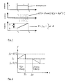
- Figure 1 shows an example for such a frequency-modulated radar signal, which is generated as a pulsed chirp signal.
- the evaluation of the phase differences based on the carrier frequency is denoted hereinafter as CW-DBF
- FM-DBF the evaluation based on the frequency-modulated signal component
- R Txu , R Rxv, T P and A R denote in this case the distance from the object to the receiver T xu , the distance from the object to the receiver R xv , the pulse duration of the radar signal and the complex amplitude of the received signal.
- the CW exponential term and the FM exponential term may be differentiated in this received signal.
- the azimuth processing is carried out using the CW exponential term. Its phase has a time-independent linear path of between 0 and 2 ⁇ and its unambiguous range is substantially determined by the relatively small wavelength ⁇ CW of the carrier signal in the denominator.
- the angular compression function is derived for the processing of frequency modulated signals with FM-DBF.
- the angular compression function for CW-DBF is known from the prior art, as CW-DBF corresponds to the previous method for determining the angle.
- the angular compression in FM-DBF also takes place after the distance compression which is also known from the prior art for determining the distance of objects.
- this type of processing may also be denoted as serial processing.
- the pulse compression the target separation has already taken place in the distance direction.
- a T denotes in this case the complex amplitude of the transmitted signal, ⁇ nuv the propagation time to the object n, starting from the transmitter T xu to the receiver R xv .
- the first exponential term is the CW term, which is conventionally utilized for DBF. It is not relevant for the derivation of the kernel function for angular compression for FM-DBF, as this angular compression is only intended to take place using the FM-term. For this reason, in this case, only the FM term is considered further.
- ⁇ FM 2 ⁇ c 0 B from the term which is relevant for processing: f RC , R ⁇ ⁇ ⁇ T ⁇ u ⁇ ⁇ e - j ⁇ 2 ⁇ ⁇ ⁇ FM ⁇ R Tx ⁇ u + R Rx ⁇ a format results which is analogous to conventional DBF.
- the angular compression starts with FM-DBF.
- the angular compression is, similar to CW-DBF, a correlation between the received signal and the complex conjugate of a reference function.
- the correlation is implemented as a summation via all transmitters and receivers, via the multiplication of the received signal and reference signal in the time range.
- the kernel function K AC,FM corresponds to the estimated path from the transmitter to the object and to the receiver for the focusing angle ⁇ 0 .
- y Tu and y Rv provide the positions
- y Tu and y Rv provide the Y coordinates of the transmitter antenna T xu and the receiver antenna R Xv .
- x Tu and x Rv denote the X-coordinates of the transmitter antenna T xu and the receiver antenna R xv .
- ⁇ n denotes the azimuth angle of the reflector n, r0 any distance for focusing.
- the target distance r n may be assumed to be constant and has no importance for the angular compression.
- the first exponential term within the sum represents the near-field term. Thus this equation describes the angular compressed signal of a point target. In this connection, merely the positions of the transmitter and of the receiver are known.
- the angle ⁇ 0 of the reference function may be understood as a test direction. If in this equation the test angle ⁇ 0 and object angle ⁇ n coincide, the angular compression produces a maximum value with the value M ⁇ N.
- CW-DBF By this additional evaluation by means of FM-DBF, ambiguities in CW-DBF may be eliminated.
- a simultaneous evaluation of the CW-phase term and FM-phase term is possible, as for example is known in the field of SAR processing by the term delta-k-technique for phase development.
- the phase terms have to have frequencies in the same order of magnitude. This is, however, not the case in the typical frequencies and bandwidths of motor-vehicle radar-technology used in the present example. For this reason, in this case by means of a specific method the CW-phase term is eliminated, in order to provide thereby the FM-phase term independently for the evaluation.
- the second exponential term corresponds to the FM term which may be utilized with FM-DBF.
- the CW term is, however, superimposed. Both terms signify a modulation of the received signal via the transmitter and receiver group.
- the path R Txu + R Rxv is of particular importance.
- the path difference and thus the phase difference for antennae along the Y-axis is proportional to sin( ⁇ n ).
- a new and efficient method is proposed in order to eliminate the CW exponential term and the periodicity involved therewith.
- it consists of two sequential measurements, in which alternately an up-chirp and a down-chirp is used in the measurement signal.
- two measurements are carried out at a distance of ⁇ t.
- the first measurement is carried out with an up-chirp and the second measurement is carried out with a down-chirp, time delayed by ⁇ t.
- Figure 2 shows the frequency response curve for up-chirp and down-chirp.
- PRF pulse repetition rate
- ⁇ t 1/PRF.
- f RC,up and f RC,down are conjugate complex multiplied with one another.
- the distance compressed signal f RC,FM established by means of two sequential measurements with an up-chirp and a down-chirp has the same character as a simple distance compressed signal.
- the bandwidth is divided up into the measurement with up-chirp and down-chirp, the distance resolution is in this case determined by B/2.
- a distance compressed signal may be obtained by two simple sequential measurements, which may be evaluated without the CW term by FM-DBF.
- the so-called FM antenna group has the receivers Rx FM at a mutual distance of ⁇ y R,FM . Their arrangement is selected relative to the wavelength ⁇ FM .
- the received signal obtained by this antenna group is evaluated by means of FM-DBF described above. In Figure 3 , this is indicated by the parallel receiver paths.
- a distance compression takes place (RC), a subsequent conjugate complex multiplication (conj.) and the angular compression(FM-DBF-AC).
- a conventional CW antenna group is used where the receivers Rx CW are at a mutual distance of ⁇ y R,CW . It is illustrated separately in Figure 3 , wherein in one embodiment of the device, however, one or more antennae also may be used both in the FM-antenna group and in the CW-antenna group.
- a distance compression (RC) and an angular compression (CW-DBF-AC) are carried out for processing the received signals of the CW-antenna group.
- RC distance compression
- CW-DBF-AC angular compression
- the conventional type of angular processing known from the prior art is used for CW-DBF.
- the results of the two angular compressions are multiplied to produce a combination, so that in the end a processed radar image is produced.
- the CW-antenna group in this case arbitrarily denoted as the first antenna group, is designed such that the desired resolution of the angular detection is achieved.
- the second antenna group is designed such that the ambiguities arising in the first antenna group, as a result of the suitably selected antenna distance of the second antenna group fall to the zero settings of the second antenna group, i.e. the FM-antenna group.
- Figure 4 shows the group factors for the FM-antenna group and CW-antenna group as well as the result of the superimposition of the two group factors.
- the ambiguity of the CW group factor falls exactly to the zero setting of the FM group factor and is no longer relevant, therefore, in the superimposition of the two group factors.
- the roots have to be taken from the product of the two linear group factors, moreover, in order to obtain a notation relating to the voltage.
- the FM-antenna group has been dimensioned in this embodiment such that it permits an unambiguous angular measurement with moderate resolution.
- the CW-antenna group forms with few antenna elements a relatively large, sparsely occupied aperture. As a result of the large aperture of the CW-antenna group relative to the wavelength ⁇ cw , a high angular resolution is achieved.
Landscapes
- Physics & Mathematics (AREA)
- Engineering & Computer Science (AREA)
- General Physics & Mathematics (AREA)
- Radar, Positioning & Navigation (AREA)
- Remote Sensing (AREA)
- Radar Systems Or Details Thereof (AREA)
- Variable-Direction Aerials And Aerial Arrays (AREA)
Abstract
Description
- The present invention relates to a method for angular determination and/or for increasing the angular resolution and/or a detectable angular range when operating antenna groups using the technique of digital beam forming, in which a measurement signal comprising a carrier signal and a frequency-modulated signal component is received via at least one antenna group directly or after reflection on one or several objects and an angle, at which the measurement signal is received by the antenna group, is determined by evaluating a phase difference in the received measurement signal, which occurs between adjacent antenna elements of the antenna group when receiving the measurement signal. The invention also relates to a device for digital beam forming which is designed to carry out the method.
- The method and the device use the technique of digital beam forming also denoted as DBF (DBF: Digital Beam Forming), in which for each receiver and/or for each antenna element used as a receiver the received signals are separately digitalised and further processed, whereby subsequent beam forming is possible when scanning an area to be monitored. By means of the method of digital beam forming, the angle may thus be determined at which, for example, radar signals are received. In the known prior art, the phase difference at a plurality of synchronously operating receiver-antenna elements in an antenna group and/or an antenna array is additionally utilized to this end. In this connection, in the known prior art any signals with a low modulation index are used as measurement signals, so that the signals are quasi-monofrequency signals. The signal processing takes place monofrequently.
- Thus K. Schuler, M. Younis, R. Lenz and W. Wiesbeck in "Array Design for Automotive Digital Beamforming Radar System", Proceedings of IEEE International Radar Conference, pp 435 - 440, May 2005, describe a method as well as a device for monitoring an area using the technique of digital beam forming, in which an antenna array is used with a plurality of transmitters and a plurality of receivers. The monitored area is depicted by means of radar, the spatial position of objects in the monitored area being determined by the dimensions of distance and angle. The angular resolution results from the phase differences of the signals received simultaneously by the different receivers.
- In the known embodiments of DBF antenna groups, care has to be taken that the maximum phase difference Δϕ determined by the maximum reception angle position ψmax does not exceed 2n at adjacent antenna elements. This requirement results in the maximum permissible distance d of the antenna elements of the respective antenna group. As a result, the physical extent of the antenna group, the so-called aperture D, is determined by the maximum reception angle to be determined and the number of antenna elements of the antenna group and/or the antenna array. The size of the aperture D is reduced with the maximum reception angle ψmax to be determined. On the other hand, the angular separation capability, i.e. the angular resolution is inversely related to the size of the aperture D. The angular resolution Δψ becomes worse with a smaller aperture. With a uniform number of antenna elements in a DBF antenna group, the angular resolution Δψ and the maximum reception angle ψmax to be determined are in opposition. If the above boundary condition is not observed, ambiguities arise when determining the angle, so-called grating lobes, when the phase difference Δϕ of adjacent antenna elements is greater than 2n.
- When operating antenna groups using the technique of digital beam forming, therefore, hitherto either a compromise had to be made between the size of the angular range ψmax which may be clearly assigned and the angular resolution Δψ or the number N of antenna elements had to be increased, so that beyond a large aperture D, with relatively small distances d between the antenna elements, phase differences of greater than 2n are avoided. If the number N of the antenna elements is increased, in order to achieve a good angular resolution Δϕ in a large unambiguous angular range, however, the costs of such an antenna array and the underlying radar circuit increase. With a given size of the antenna elements, additionally the distances d may not be freely selected, as if the distances are too small, couplings of the antenna elements occur which cause additional errors when determining the angle.
-
DE 10105240 A1 discloses a radar apparatus with a reception array antenna having a plurality of antenna elements, a first bearing detector for detecting a bearing of a target by carrying out signal processing on individual element signals received on an element-by-element basis through the respective antenna elements, and a second bearing detector for detecting a bearing of a target by carrying out signal processing different from that of the first bearing detector, on the individual element signals received through the respective antenna elements. For the determination of reception angle or direction a subdivision into near-field and far-field is made and the two fields are processed in a different manner. The processing is complex. This document does not deal with the problems of grating lobes. - It is an object of the present invention to provide a method for angular determination by means of digital beam forming as well as a device for carrying out the method, by which the angular resolution and the angular range, which may be detected in an unambiguous manner, may be cost-effectively increased or by which an alternative possibility for the angular determination is provided.
- The object is achieved with the method according to Claim 1 and the device according to Claim 8. Advantageous embodiments of the method and of the device form the subject of the dependent claims or may be derived from the following description as well as the embodiment.
- In the proposed method, a measurement signal, which in addition to a carrier signal also comprises a frequency-modulated signal component, is directly received via at least one antenna group or after reflection on one or several objects. The angle, at which the measurement signal is received by the antenna group, is determined by evaluating a phase difference in the received measurement signal, which occurs between adjacent antenna elements of the antenna group when receiving the measurement signal. The proposed method is characterised in that for determining the phase difference, additionally to the previously carried-out evaluation of the carrier signal, the frequency-modulated signal component is also evaluated or the frequency-modulated signal component is exclusively evaluated.
- It is essential in this connection that the frequency-modulated signal component contributes to the angular determination alone or in combination with the carrier signal.
- By the additional evaluation of the frequency-modulated signal component, ambiguities in the angular determination may be identified and resolved, so that without altering the number N of antenna elements an unambiguous angular determination is achieved over a greater angular range ψmax than previously. In contrast, by means of the method, even with an angular range ψmax which remains the same and which may be detected in an unambiguous manner, the angular resolution Δψ may be increased without altering the number N of antenna elements, as the interval d of the antenna elements may be increased without considering the previously occurring ambiguities. Moreover, with the proposed method, if required, even the number N of antenna elements may be reduced without altering the angular range ψmax, which may be assigned in an unambiguous manner, and the angular resolution Δψ .
- If the size of the unambiguous angular range ψmax, maintaining a good angular resolution Δψ, is increased in the previous prior art, this leads to phase differences Δϕ at adjacent antenna elements of greater than 2n. With the proposed method, such phase differences at adjacent antenna elements of greater than 2π may be identified and thus made unambiguous. This means that with a phase difference of Δϕ = n·2π + ϕdiff where n = 0,1,2,... the factor n may be determined. This determination takes place by the evaluation of the additional signal component. The additional signal component is in the proposed method obtained by a frequency modulation of the measurement signal.
- The provision of a measurement signal with a frequency-modulated signal component, for example a frequency-modulated radar signal, generally does not represent any additional cost, as such a signal component is already present in many applications. Thus the frequency modulation of the measurement signal represents a common method in radar technology, in order to improve the distance resolution. The frequency modulation is accordingly used in any case, when the distance from objects is to be determined by means of the class of the pulsed chirp radar system or FMCW radar system. The frequency modulation is ignored in the previous DBF-processing methods, as generally in this application it only comprises a low frequency deviation, and the signal is thus quasi-monofrequent. The proposed method is thus characterised by this frequency-modulated signal component, which was hitherto ignored for the angular determination, being specifically evaluated. The measurement signal is thus evaluated in all its signal components, so that the hitherto monofrequent signal processing in DBF is increased by a signal processing adapted to the frequency modulation. The evaluation of two signal components in one antenna group is equivalent to the evaluation of two different antenna groups, in which respectively the same signal is used with only one signal component. Thus the evaluation of both signal components replaces the formation of a second antenna group, in particular in cases in which the bandwidth B of the frequency modulation is in the order of magnitude of the carrier frequency, i.e. namely between 0.1·f0 and f0.
- With suitable dimensioning of this one antenna group and/or with a suitable choice of carrier frequency f0 and bandwidth B of the frequency modulation, the achievable angular resolution and the size of the angle segment which may be clearly depicted may be made independent of one another. It is possible for high transmitter frequency f0, that Δϕ0 = 2π·Δr/λ0 > 2n, if Δr > λ0, Δr corresponding to the difference in the distance between adjacent antenna elements from a point target, from which the measurement signal is received. The unambiguity is achieved by the low modulation frequency fFM, as ΔϕFM = 2π·Δr/λFM is substantially less than 2n, as λFM is very high relative to λ0. When multiplying the two results, the high angular resolution is achieved by f0 and the unambiguity by fFM. Both frequencies are present simultaneously in a frequency-modulated radar signal. The type of frequency modulation is in this case not important. Thus, for example, it may be a chirp, i.e. a linear modulation, or even a quadratic modulation.
- The device used for implementing the method for digital beam forming comprises at least one antenna group for receiving a measurement signal, which comprises a carrier signal and a frequency-modulated signal component, and an evaluation device. The evaluation device evaluates the measurement signal received via the antenna group by means of digital beam forming, in order to determine at least the angle at which the measurement signal is received by the antenna group. The angle is determined by evaluating a phase difference in the received measurement signal, which occurs between adjacent antenna elements of the antenna group when receiving the measurement signal. The evaluation device is thus configured such that for determining the phase difference it also evaluates exclusively, or additionally to an evaluation of the carrier signal, the frequency-modulated signal component.
- The device may comprise at least one transmitter device, which transmits a frequency-modulated radar signal as the measurement signal.
- By utilizing the frequency-modulated component, the compromise may be avoided that conclusions generally have to be drawn between the angular range which may be depicted in an unambiguous manner and the achievable angular resolution. To this end, the antenna group is designed relative to the carrier frequency and the bandwidth of the signal such that, for example with conventional DBF processing, also denoted hereinafter as CW-DBF, by evaluating the carrier signal component a good angular resolution is achieved and with the additional evaluation of the frequency-modulated signal component, also denoted hereinafter as FM-DBF, a larger, unambiguous angular range is achieved. Without the above advantage, the angle may also be exclusively determined by utilizing the frequency-modulated component (FM-DBF).
- The method and the device may in this connection primarily be used advantageously in radar technology. Naturally, however, other application fields are also possible, such as for example an application in communication technology for determining the direction of incidence of transmitted signals, if said signals comprise low frequency components.
- In a preferred embodiment of the method as well as the device, therefore, not only angles but also distances from one or more objects are determined. In this connection, preferably from one or more transmitters of the device, a frequency-modulated radar signal is transmitted as a measurement signal and, after reflection on one or several objects in a monitored area, is received via at least one antenna group. After distance compression for determining the distance of the one or several objects, on which the radar signal has been reflected, the angular compression relative to the carrier frequency component and the angular compression relative to the frequency-modulated component then take place. The techniques of distance compression and angular compression are known to the person skilled in the art from the processing of signals previously carried out during digital beam forming. The angular compression is based on a discrete Fourier transform. In contrast to conventional DBF processing, during the evaluation of the frequency-modulated component a standardization to λFM may be used.
- Particularly advantageously, the method and the device may be used if the frequency modulation may be selected in the order of magnitude of the carrier frequency. In this case, the two signal components, i.e. the signal component based on the carrier frequency as well as the frequency-modulated signal component, may be easily evaluated simultaneously. The bandwidth of the frequency modulation should in this case preferably be at least 20% of the carrier frequency.
- If such a large bandwidth of the frequency modulation is not possible, such as for example in measurement signals used hitherto in motor-vehicle close-range radar technology, the signal component based on the frequency modulation during the evaluation is therefore very small relative to the component based on the carrier frequency. In this case, it is advantageous to evaluate the two components separately, it being intended that for the evaluation of the frequency-modulated signal component, the signal component based on the carrier frequency is eliminated. This may take place by a sequential measurement, in which during the first measurement a measurement signal is used with an up-chirp and during the second measurement a measurement signal is used with a down-chirp or vice versa. By combining both measurements, the signal component based on the carrier frequency may be eliminated, so that the signal component based on the frequency modulation may be evaluated separately. An elimination of the signal component based on the carrier frequency may be also implemented by other techniques, and is only necessary in cases in which the frequency-modulated signal component is very small relative to the signal component based on the carrier frequency.
- In one embodiment, in particular if the bandwidth of the frequency modulation is small relative to the carrier frequency, at least two antenna groups are used for the method and the device, in which the antenna elements of the first antenna group are adjusted to a high resolution by evaluating the carrier frequency and the antenna elements of the second antenna group are adjusted to the unambiguity by evaluating the frequency-modulated signal component. This adjustment relates to the distance between the individual antenna elements. Both antenna groups may also have common antenna elements. All antenna elements of the two antenna groups may also coincide. Particularly advantageously, the antenna elements of the first antenna group and the second antenna group are adjusted to one another such that during processing of the digital beam forming for determining the angle, ambiguities in the group factor of the first antenna group fall to a specific value, preferably to minimum values or zero settings, of the group factor of the second antenna group.
- The proposed method and the associated device are described again in more detail hereinafter with reference to an embodiment in combination with the drawings, in which:
-
figure 1 shows an example of a measurement signal comprising a carrier frequency and a frequency-modulated signal component, as may be used in the proposed method; -
figure 2 shows an exemplary frequency response curve for up-chirp and down-chirp; -
figure 3 shows a block diagram of an exemplary embodiment of the present invention; and -
figure 4 shows an example of the group factors of the antenna groups in the embodiment according tofigure 3 . - The exemplary embodiment disclosed hereinafter relates to an application of the method and the device to the field of motor-vehicle close-range radar. In this field, generally a measurement signal is used with a carrier frequency of f0 = 24 GHz and a bandwidth of the frequency modulation of B = 250 MHz or even up to 5 GHz.
Figure 1 shows an example for such a frequency-modulated radar signal, which is generated as a pulsed chirp signal. The evaluation of the phase differences based on the carrier frequency is denoted hereinafter as CW-DBF, the evaluation based on the frequency-modulated signal component is denoted as FM-DBF. In order to distinguish CW-DBF and FM-DBF clearly from one another, in this connection the wavelength belonging to the carrier frequency is explicitly denoted by λCW and the wavelength belonging to the frequency modulation is denoted by λFM. The received signal sR(t) of the antenna group results in:
- RTxu, RRxv, TP and AR denote in this case the distance from the object to the receiver Txu, the distance from the object to the receiver Rxv, the pulse duration of the radar signal and the complex amplitude of the received signal. The CW exponential term and the FM exponential term may be differentiated in this received signal. In conventional CW-DBF the azimuth processing is carried out using the CW exponential term. Its phase has a time-independent linear path of between 0 and 2π and its unambiguous range is substantially determined by the relatively small wavelength λCW of the carrier signal in the denominator.
- The FM exponential term which is also used hereinafter for azimuth processing with FM-DBF, has a time-dependent quadratic path. Its unambiguous range, however, at constant time t is primarily determined by the chirp rate ke = B/(2Tp) in the numerator. In both cases, i.e. the conventional CW-DBF and the new FM-DBF concept, the actual unambiguous range depends on antenna distance. From the above equation, it may be seen that two exponential terms are contained in the received signal, which initially are superimposed and in principle are both available for evaluation.
- Hereinafter, the angular compression function, the so-called kernel function, is derived for the processing of frequency modulated signals with FM-DBF. The angular compression function for CW-DBF is known from the prior art, as CW-DBF corresponds to the previous method for determining the angle.
- The angular compression in FM-DBF also takes place after the distance compression which is also known from the prior art for determining the distance of objects. Thus this type of processing may also be denoted as serial processing. As a result of the pulse compression, the target separation has already taken place in the distance direction. The distance compressed signal, at which the angular processing is to take place, for the pulsed chirp signal is as follows:

- AT denotes in this case the complex amplitude of the transmitted signal, τnuv the propagation time to the object n, starting from the transmitter Txu to the receiver Rxv. The first exponential term is the CW term, which is conventionally utilized for DBF. It is not relevant for the derivation of the kernel function for angular compression for FM-DBF, as this angular compression is only intended to take place using the FM-term. For this reason, in this case, only the FM term is considered further.

- The angular compression takes place for each distance cell individually. If a distance cell is considered, τ = const for all transmitter-receiver combinations and thus is not relevant for the azimuth processing. As a result, only the term:


- In this case, the angular compression starts with FM-DBF. The angular compression is, similar to CW-DBF, a correlation between the received signal and the complex conjugate of a reference function. The correlation is implemented as a summation via all transmitters and receivers, via the multiplication of the received signal and reference signal in the time range. The angular compressed signal fAC,FM is thus dependent on the focusing angle ψ0:

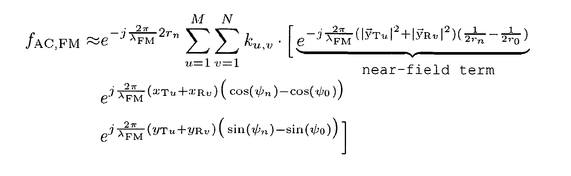
y Tu andy Rv provide the positions, yTu and yRv provide the Y coordinates of the transmitter antenna Txu and the receiver antenna RXv. xTu and xRv denote the X-coordinates of the transmitter antenna Txu and the receiver antenna Rxv. ψn denotes the azimuth angle of the reflector n, r0 any distance for focusing. The target distance rn may be assumed to be constant and has no importance for the angular compression. The first exponential term within the sum represents the near-field term. Thus this equation describes the angular compressed signal of a point target. In this connection, merely the positions of the transmitter and of the receiver are known. After distance compression, also the target distance rn is known. The angle ψ0 of the reference function may be understood as a test direction. If in this equation the test angle ψ0 and object angle ψn coincide, the angular compression produces a maximum value with the value M·N. - By this additional evaluation by means of FM-DBF, ambiguities in CW-DBF may be eliminated. In principle, in this case a simultaneous evaluation of the CW-phase term and FM-phase term is possible, as for example is known in the field of SAR processing by the term delta-k-technique for phase development. To this end, the phase terms have to have frequencies in the same order of magnitude. This is, however, not the case in the typical frequencies and bandwidths of motor-vehicle radar-technology used in the present example. For this reason, in this case by means of a specific method the CW-phase term is eliminated, in order to provide thereby the FM-phase term independently for the evaluation. To this end, the received signal after distance compression is once again provided as:

- The second exponential term corresponds to the FM term which may be utilized with FM-DBF. The CW term is, however, superimposed. Both terms signify a modulation of the received signal via the transmitter and receiver group. In this case, the path RTxu + RRxv is of particular importance. For targets in the distant field, the path difference and thus the phase difference for antennae along the Y-axis is proportional to sin(ψn). In this case, the CW term is changing more rapidly than the FM term, if the conventional parameters, such as for example a carrier frequency f0 = 24 GHz and ke = B/(2·Tp) = 500 MHz/(2·0.5 µs), are assumed. The wavelengths thus are λFM = 1.2 m and λCW = 12.5 mm. The further the carrier frequency f0 and the bandwidth are apart, the more marked is this difference. For this reason, in conventional CW-DBF, the FM exponential term may be ignored. If it were desired to utilize this FM-exponential term, however, the CW exponential term would produce interference as a result of its high frequency.
- Hereinafter, a new and efficient method is proposed in order to eliminate the CW exponential term and the periodicity involved therewith. In this case it consists of two sequential measurements, in which alternately an up-chirp and a down-chirp is used in the measurement signal. On each receiver, two measurements are carried out at a distance of Δt. In this case, the first measurement is carried out with an up-chirp and the second measurement is carried out with a down-chirp, time delayed by Δt.
Figure 2 shows the frequency response curve for up-chirp and down-chirp. For the signals the following applies:

- The chirp rates in this case have an opposite sign and thus the following applies:

- This definition has the effect that up-chirp and down-chirp together have exactly the bandwidth B. The relevant bandwidth has thus been halved by the modulation. Thus also the modulation wavelength has now been doubled λFM = 4c0/B. For calculating the received signals, a point target is assumed. As a result, on each receiver respectively one receiver signal is produced for up-chirp and down-chirp:


- A distance compression is separately carried out for both received signals. As a result, the two distance compressed signals produce:
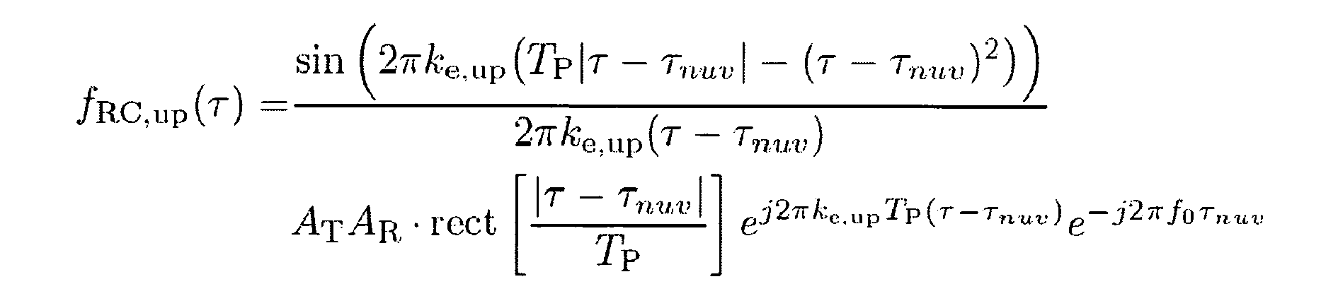

- The time duration Δt between the up-chirp and down-chirp is established by the pulse repetition rate PRF with Δt = 1/PRF. Hereinafter, a stationary scenario is to be assumed. Thus Δt = 0 may be assumed so that fRC,down(τ-Δt) = fRC,down(τ). For eliminating the CW term the two distance compressed signals fRC,up and fRC,down are conjugate complex multiplied with one another. The root again produces a voltage magnitude from the power rating

- The distance compressed signal fRC,FM established by means of two sequential measurements with an up-chirp and a down-chirp, has the same character as a simple distance compressed signal. As the bandwidth is divided up into the measurement with up-chirp and down-chirp, the distance resolution is in this case determined by B/2. Thus a distance compressed signal may be obtained by two simple sequential measurements, which may be evaluated without the CW term by FM-DBF.
- For carrying out the proposed method, i.e. the combination of FM-DBF and CW-DBF, and for the configuration of the associated device, in the present example two antenna groups are used, as is visible from the block diagram of
figure 3 . The so-called FM antenna group has the receivers RxFM at a mutual distance of ΔyR,FM. Their arrangement is selected relative to the wavelength λFM. The received signal obtained by this antenna group is evaluated by means of FM-DBF described above. InFigure 3 , this is indicated by the parallel receiver paths. For each of the two measurements for eliminating the CW exponential term, a distance compression takes place (RC), a subsequent conjugate complex multiplication (conj.) and the angular compression(FM-DBF-AC). - Additionally to this antenna group a conventional CW antenna group is used where the receivers RxCW are at a mutual distance of ΔyR,CW . It is illustrated separately in
Figure 3 , wherein in one embodiment of the device, however, one or more antennae also may be used both in the FM-antenna group and in the CW-antenna group. For processing the received signals of the CW-antenna group also a distance compression (RC) and an angular compression (CW-DBF-AC) are carried out. In this case the conventional type of angular processing known from the prior art is used for CW-DBF. - The results of the two angular compressions are multiplied to produce a combination, so that in the end a processed radar image is produced.
In order to combine the two antenna groups optimally with one another, they should be adjusted to one another. To this end, the CW-antenna group, in this case arbitrarily denoted as the first antenna group, is designed such that the desired resolution of the angular detection is achieved. The second antenna group is designed such that the ambiguities arising in the first antenna group, as a result of the suitably selected antenna distance of the second antenna group fall to the zero settings of the second antenna group, i.e. the FM-antenna group. - For the following example, an FM-antenna group and a CW-antenna group are used with respectively NFM = NCW = 3 receiver antennae and a common transmitter antenna. The distance in the FM antenna group is in this case ΔyR,FM = 0.5·λFM = 0.5·4c0/B = 1.2 m where B = 500 MHz. In the CW-antenna group the distance ΔyR,CW = 1.5·λCW = 18.75 mm. In principle, in this case it is unimportant in which antenna group the greater distance occurs. However, in the example selected here it is more useful to use the smaller distance in the FM-antenna group, so that as a result of the greater wavelength λFM this antenna arrangement does not become even greater. Thus possible near-field errors remain as small as possible.
-
Figure 4 shows the group factors for the FM-antenna group and CW-antenna group as well as the result of the superimposition of the two group factors. As in this embodiment respectively only NCW = NFM = 3 antennae are used, for both group factors a higher secondary maximum results than - 13dB which is usual for this field. The ambiguity of the CW group factor falls exactly to the zero setting of the FM group factor and is no longer relevant, therefore, in the superimposition of the two group factors. For the superimposition of the two group factors, the roots have to be taken from the product of the two linear group factors, moreover, in order to obtain a notation relating to the voltage. - By utilizing the novel FM-DBF and the combination of FM-DBF and CW-DBF proposed here, ambiguities in CW-DBF may be eliminated. The FM-antenna group has been dimensioned in this embodiment such that it permits an unambiguous angular measurement with moderate resolution. The CW-antenna group forms with few antenna elements a relatively large, sparsely occupied aperture. As a result of the large aperture of the CW-antenna group relative to the wavelength λcw, a high angular resolution is achieved.
Claims (15)
- Method for angular determination and/or for increasing an angular resolution and/or a detectable angular range when operating antenna groups using the technique of digital beam forming (DBF), in which- a measurement signal comprising a carrier signal and a frequency-modulated signal component is received via at least one antenna group directly or after reflection on one or several objects, and- an angle, at which the measurement signal is received by the antenna group, is determined by evaluating a phase difference in the received measurement signal, which occurs between adjacent antenna elements of the antenna group when receiving the measurement signal,characterised in that
for determining the phase difference the frequency-modulated signal component is also evaluated, exclusively or additionally to an evaluation of the carrier signal. - Method according to Claim 1,
characterised in that
said measurement signal has a carrier frequency and a frequency modulation, in which a bandwidth of the frequency modulation is in the order of magnitude of the carrier frequency. - Method according to Claim 1 or 2,
characterised in that
two antenna groups are used, of which a first antenna group is configured for a high angular resolution relative to the second antenna group by evaluating the carrier signal, and the second antenna group is configured for evaluating the frequency-modulated signal component. - Method according to Claim 3,
characterised in that
one or several or all antenna elements of the first antenna group are also used as a component of the second antenna group. - Method according to Claim 3 or 4,
characterised in that
distances between the antenna elements of the first and second antenna group are selected such that ambiguities of a first group factor during the evaluation of the carrier signal using the first antenna group fall to minimum values, in particular zero settings, of a second group factor during evaluation of the frequency-modulated signal component using the second antenna group. - Method according to one of Claims 1 to 5,
characterised in that
for eliminating a term based on the carrier signal during evaluation of the frequency-modulated signal component a sequential measurement is carried out, in which a first measurement signal is used with an up-chirp and a second measurement signal is used with a down-chirp - or vice versa. - Method according to one of Claims 1 to 6,
characterised in that
a distance of said one or several objects is additionally determined via an evaluation of the measurement signal. - Device for digital beam forming (DBF) comprising- at least one antenna group for receiving a measurement signal, which comprises a carrier signal and a frequency-modulated signal component, and- an evaluation device which evaluates the measurement signal received via the antenna group by means of digital beam forming, in order to determine at least one angle at which the measurement signal is received by the antenna group, the angle being determined by evaluating a phase difference in the received measurement signal, which occurs between adjacent antenna elements of the antenna group when receiving the measurement signal,characterised in that
the evaluation device is configured such that for determining the phase difference it also evaluates the frequency-modulated signal component of the received measurement signal, exclusively or additionally to an evaluation of the carrier signal. - Device according to Claim 8,
characterised in that
the device further comprises a transmitter device which transmits the measurement signal into an area to be monitored. - Device according to Claim 9,
characterised in that
the transmitter device transmits said measurement signal with a carrier frequency and a frequency modulation, in which a bandwidth of the frequency modulation is in the order of magnitude of the carrier frequency. - Device according to Claim 9 or 10,
characterised in that
the transmitter device is configured such that it alternately transmits a first measurement signal with an up-chirp and a second measurement signal with a down-chirp - or vice versa. - Device according to one of Claims 8 to 11,
characterised in that
the evaluation device is configured such that it determines a distance from one or more objects via an evaluation of the received measurement signal. - Device according to one of Claims 8 to 12,
characterised in that
the device comprises two antenna groups of which a first antenna group is configured for a high angular resolution relative to a second antenna group by evaluating the carrier signal and the second antenna group is configured for evaluating the frequency-modulated signal component. - Device according to Claim 13,
characterised in that
the two antenna groups comprise one or several common antenna elements. - Device according to Claim 13 or 14,
characterised in that
distances between the antenna elements of the first and second antenna group are selected such that ambiguities of a first group factor during evaluation of the carrier signal using the first antenna group fall to minimum values, in particular zero settings, of a second group factor during evaluation of the frequency-modulated signal component using the second antenna group.
Applications Claiming Priority (1)
| Application Number | Priority Date | Filing Date | Title |
|---|---|---|---|
| DE102008011889A DE102008011889A1 (en) | 2008-02-29 | 2008-02-29 | Digital beamforming with frequency modulated signals |
Publications (3)
| Publication Number | Publication Date |
|---|---|
| EP2096457A2 true EP2096457A2 (en) | 2009-09-02 |
| EP2096457A3 EP2096457A3 (en) | 2011-07-06 |
| EP2096457B1 EP2096457B1 (en) | 2014-10-29 |
Family
ID=40671107
Family Applications (1)
| Application Number | Title | Priority Date | Filing Date |
|---|---|---|---|
| EP09002786.3A Not-in-force EP2096457B1 (en) | 2008-02-29 | 2009-02-26 | Digital beam forming using frequency-modulated signals |
Country Status (3)
| Country | Link |
|---|---|
| US (1) | US7961139B2 (en) |
| EP (1) | EP2096457B1 (en) |
| DE (1) | DE102008011889A1 (en) |
Cited By (1)
| Publication number | Priority date | Publication date | Assignee | Title |
|---|---|---|---|---|
| CN103353587A (en) * | 2013-06-13 | 2013-10-16 | 西安电子科技大学 | Interference angle-measuring method based on improved self-adaptive DBF (digital beam forming) |
Families Citing this family (6)
| Publication number | Priority date | Publication date | Assignee | Title |
|---|---|---|---|---|
| JP5071414B2 (en) * | 2009-03-04 | 2012-11-14 | 株式会社デンソー | Radar equipment |
| KR20110126939A (en) * | 2010-05-18 | 2011-11-24 | 주식회사 만도 | Integrated Radar System and Vehicle Control System |
| EP2492709A1 (en) * | 2011-02-25 | 2012-08-29 | Nederlandse Organisatie voor toegepast -natuurwetenschappelijk onderzoek TNO | FMCW radar system |
| US10386480B1 (en) | 2016-02-02 | 2019-08-20 | Waymo Llc | Radar based mapping and localization for autonomous vehicles |
| EP3432027B1 (en) * | 2017-07-20 | 2021-09-01 | Airbus Defence and Space GmbH | High resolution wide swath synthetic aperture radar system |
| DE102018214586A1 (en) * | 2018-08-29 | 2020-03-05 | Robert Bosch Gmbh | Device for receiving light for the detection of an object |
Citations (1)
| Publication number | Priority date | Publication date | Assignee | Title |
|---|---|---|---|---|
| DE10105240A1 (en) | 2000-02-07 | 2001-08-16 | Toyota Motor Co Ltd | Radar apparatus for cars, has pair of bearing detectors which carry out signal processing, in different manners |
Family Cites Families (5)
| Publication number | Priority date | Publication date | Assignee | Title |
|---|---|---|---|---|
| JP2585448B2 (en) * | 1990-03-09 | 1997-02-26 | 三菱電機株式会社 | Radar equipment |
| US6573859B2 (en) | 2000-02-07 | 2003-06-03 | Toyota Jidosha Kabushiki Kaisha | Radar apparatus |
| US20050195103A1 (en) * | 2004-01-13 | 2005-09-08 | Davis Dennis W. | Phased arrays exploiting geometry phase and methods of creating such arrays |
| DK1735637T3 (en) * | 2004-04-05 | 2019-04-29 | Weibel Scient A/S | System and method for radar detection of an object. |
| JP2006047114A (en) * | 2004-08-04 | 2006-02-16 | Fujitsu Ten Ltd | Radar equipment |
-
2008
- 2008-02-29 DE DE102008011889A patent/DE102008011889A1/en not_active Withdrawn
-
2009
- 2009-02-16 US US12/371,733 patent/US7961139B2/en not_active Expired - Fee Related
- 2009-02-26 EP EP09002786.3A patent/EP2096457B1/en not_active Not-in-force
Patent Citations (1)
| Publication number | Priority date | Publication date | Assignee | Title |
|---|---|---|---|---|
| DE10105240A1 (en) | 2000-02-07 | 2001-08-16 | Toyota Motor Co Ltd | Radar apparatus for cars, has pair of bearing detectors which carry out signal processing, in different manners |
Non-Patent Citations (1)
| Title |
|---|
| K. SCHULER ET AL.: "Array Design for Automotive Digital Beamforming Radar System", PROCEEDINGS OF IEEE INTERNATIONAL RADAR CONFERENCE, May 2005 (2005-05-01), pages 435 - 440 |
Cited By (2)
| Publication number | Priority date | Publication date | Assignee | Title |
|---|---|---|---|---|
| CN103353587A (en) * | 2013-06-13 | 2013-10-16 | 西安电子科技大学 | Interference angle-measuring method based on improved self-adaptive DBF (digital beam forming) |
| CN103353587B (en) * | 2013-06-13 | 2015-01-28 | 西安电子科技大学 | Interference angle-measuring method based on improved self-adaptive DBF (digital beam forming) |
Also Published As
| Publication number | Publication date |
|---|---|
| DE102008011889A1 (en) | 2009-10-01 |
| EP2096457B1 (en) | 2014-10-29 |
| US20090219208A1 (en) | 2009-09-03 |
| US7961139B2 (en) | 2011-06-14 |
| EP2096457A3 (en) | 2011-07-06 |
Similar Documents
| Publication | Publication Date | Title |
|---|---|---|
| JP7667331B2 (en) | Method and apparatus for capturing surroundings - Patents.com | |
| EP3611538B1 (en) | Mimo radar coding for resolving velocity ambiguity | |
| EP3220162B1 (en) | Radar device and position-determination method | |
| US10539645B2 (en) | Angle of arrival estimation | |
| KR102799877B1 (en) | Radar system with interleaved serial transmission and parallel reception | |
| US9921305B2 (en) | Radar apparatus and object sensing method | |
| EP3021132B1 (en) | Mimo radar system | |
| US7791530B2 (en) | Time duplex apparatus and method for radar sensor front-ends | |
| US7928897B2 (en) | Target detection method for use in radar and radar device using the target detection method | |
| EP1757953B1 (en) | FM-CW radar system | |
| US8947293B2 (en) | Radar apparatus | |
| JP3821688B2 (en) | Radar equipment | |
| EP2096457B1 (en) | Digital beam forming using frequency-modulated signals | |
| US20080088499A1 (en) | Methods and apparatus for hyperview automotive radar | |
| DE102018100632A1 (en) | Radar method and system for determining the angular position, the location and / or the, in particular vectorial, speed of a target | |
| US20250231284A1 (en) | Radar device | |
| JP4769596B2 (en) | Electronic scanning radar equipment | |
| JP7224292B2 (en) | Radar device and automobile equipped with it | |
| JP3865761B2 (en) | Radar equipment | |
| US11960023B2 (en) | Radar device | |
| US20240036183A1 (en) | Radar method and radar system for a phase-coherent analysis | |
| JP2011163894A (en) | Object detecting device and object detecting method | |
| Sardo et al. | STDCC radar at 24 GHz: first measurement trials |
Legal Events
| Date | Code | Title | Description |
|---|---|---|---|
| PUAI | Public reference made under article 153(3) epc to a published international application that has entered the european phase |
Free format text: ORIGINAL CODE: 0009012 |
|
| AK | Designated contracting states |
Kind code of ref document: A2 Designated state(s): AT BE BG CH CY CZ DE DK EE ES FI FR GB GR HR HU IE IS IT LI LT LU LV MC MK MT NL NO PL PT RO SE SI SK TR |
|
| AX | Request for extension of the european patent |
Extension state: AL BA RS |
|
| RAP1 | Party data changed (applicant data changed or rights of an application transferred) |
Owner name: KARLSRUHER INSTITUT FUER TECHNOLOGIE |
|
| PUAL | Search report despatched |
Free format text: ORIGINAL CODE: 0009013 |
|
| AK | Designated contracting states |
Kind code of ref document: A3 Designated state(s): AT BE BG CH CY CZ DE DK EE ES FI FR GB GR HR HU IE IS IT LI LT LU LV MC MK MT NL NO PL PT RO SE SI SK TR |
|
| AX | Request for extension of the european patent |
Extension state: AL BA RS |
|
| 17P | Request for examination filed |
Effective date: 20111215 |
|
| AKX | Designation fees paid |
Designated state(s): AT BE BG CH CY CZ DE DK EE ES FI FR GB GR HR HU IE IS IT LI LT LU LV MC MK MT NL NO PL PT RO SE SI SK TR |
|
| GRAP | Despatch of communication of intention to grant a patent |
Free format text: ORIGINAL CODE: EPIDOSNIGR1 |
|
| INTG | Intention to grant announced |
Effective date: 20140514 |
|
| GRAS | Grant fee paid |
Free format text: ORIGINAL CODE: EPIDOSNIGR3 |
|
| GRAA | (expected) grant |
Free format text: ORIGINAL CODE: 0009210 |
|
| AK | Designated contracting states |
Kind code of ref document: B1 Designated state(s): AT BE BG CH CY CZ DE DK EE ES FI FR GB GR HR HU IE IS IT LI LT LU LV MC MK MT NL NO PL PT RO SE SI SK TR |
|
| REG | Reference to a national code |
Ref country code: GB Ref legal event code: FG4D |
|
| REG | Reference to a national code |
Ref country code: CH Ref legal event code: EP |
|
| REG | Reference to a national code |
Ref country code: AT Ref legal event code: REF Ref document number: 693845 Country of ref document: AT Kind code of ref document: T Effective date: 20141115 |
|
| REG | Reference to a national code |
Ref country code: IE Ref legal event code: FG4D |
|
| REG | Reference to a national code |
Ref country code: DE Ref legal event code: R096 Ref document number: 602009027400 Country of ref document: DE Effective date: 20141211 |
|
| REG | Reference to a national code |
Ref country code: FR Ref legal event code: PLFP Year of fee payment: 7 |
|
| REG | Reference to a national code |
Ref country code: AT Ref legal event code: MK05 Ref document number: 693845 Country of ref document: AT Kind code of ref document: T Effective date: 20141029 |
|
| REG | Reference to a national code |
Ref country code: NL Ref legal event code: VDEP Effective date: 20141029 |
|
| REG | Reference to a national code |
Ref country code: LT Ref legal event code: MG4D |
|
| PG25 | Lapsed in a contracting state [announced via postgrant information from national office to epo] |
Ref country code: LT Free format text: LAPSE BECAUSE OF FAILURE TO SUBMIT A TRANSLATION OF THE DESCRIPTION OR TO PAY THE FEE WITHIN THE PRESCRIBED TIME-LIMIT Effective date: 20141029 Ref country code: IS Free format text: LAPSE BECAUSE OF FAILURE TO SUBMIT A TRANSLATION OF THE DESCRIPTION OR TO PAY THE FEE WITHIN THE PRESCRIBED TIME-LIMIT Effective date: 20150228 Ref country code: NL Free format text: LAPSE BECAUSE OF FAILURE TO SUBMIT A TRANSLATION OF THE DESCRIPTION OR TO PAY THE FEE WITHIN THE PRESCRIBED TIME-LIMIT Effective date: 20141029 Ref country code: FI Free format text: LAPSE BECAUSE OF FAILURE TO SUBMIT A TRANSLATION OF THE DESCRIPTION OR TO PAY THE FEE WITHIN THE PRESCRIBED TIME-LIMIT Effective date: 20141029 Ref country code: PT Free format text: LAPSE BECAUSE OF FAILURE TO SUBMIT A TRANSLATION OF THE DESCRIPTION OR TO PAY THE FEE WITHIN THE PRESCRIBED TIME-LIMIT Effective date: 20150302 Ref country code: NO Free format text: LAPSE BECAUSE OF FAILURE TO SUBMIT A TRANSLATION OF THE DESCRIPTION OR TO PAY THE FEE WITHIN THE PRESCRIBED TIME-LIMIT Effective date: 20150129 Ref country code: ES Free format text: LAPSE BECAUSE OF FAILURE TO SUBMIT A TRANSLATION OF THE DESCRIPTION OR TO PAY THE FEE WITHIN THE PRESCRIBED TIME-LIMIT Effective date: 20141029 |
|
| PGFP | Annual fee paid to national office [announced via postgrant information from national office to epo] |
Ref country code: DE Payment date: 20150216 Year of fee payment: 7 |
|
| PG25 | Lapsed in a contracting state [announced via postgrant information from national office to epo] |
Ref country code: CY Free format text: LAPSE BECAUSE OF FAILURE TO SUBMIT A TRANSLATION OF THE DESCRIPTION OR TO PAY THE FEE WITHIN THE PRESCRIBED TIME-LIMIT Effective date: 20141029 Ref country code: SE Free format text: LAPSE BECAUSE OF FAILURE TO SUBMIT A TRANSLATION OF THE DESCRIPTION OR TO PAY THE FEE WITHIN THE PRESCRIBED TIME-LIMIT Effective date: 20141029 Ref country code: PL Free format text: LAPSE BECAUSE OF FAILURE TO SUBMIT A TRANSLATION OF THE DESCRIPTION OR TO PAY THE FEE WITHIN THE PRESCRIBED TIME-LIMIT Effective date: 20141029 Ref country code: LV Free format text: LAPSE BECAUSE OF FAILURE TO SUBMIT A TRANSLATION OF THE DESCRIPTION OR TO PAY THE FEE WITHIN THE PRESCRIBED TIME-LIMIT Effective date: 20141029 Ref country code: GR Free format text: LAPSE BECAUSE OF FAILURE TO SUBMIT A TRANSLATION OF THE DESCRIPTION OR TO PAY THE FEE WITHIN THE PRESCRIBED TIME-LIMIT Effective date: 20150130 Ref country code: AT Free format text: LAPSE BECAUSE OF FAILURE TO SUBMIT A TRANSLATION OF THE DESCRIPTION OR TO PAY THE FEE WITHIN THE PRESCRIBED TIME-LIMIT Effective date: 20141029 Ref country code: HR Free format text: LAPSE BECAUSE OF FAILURE TO SUBMIT A TRANSLATION OF THE DESCRIPTION OR TO PAY THE FEE WITHIN THE PRESCRIBED TIME-LIMIT Effective date: 20141029 |
|
| PGFP | Annual fee paid to national office [announced via postgrant information from national office to epo] |
Ref country code: GB Payment date: 20150223 Year of fee payment: 7 Ref country code: FR Payment date: 20150217 Year of fee payment: 7 |
|
| REG | Reference to a national code |
Ref country code: DE Ref legal event code: R097 Ref document number: 602009027400 Country of ref document: DE |
|
| PG25 | Lapsed in a contracting state [announced via postgrant information from national office to epo] |
Ref country code: SK Free format text: LAPSE BECAUSE OF FAILURE TO SUBMIT A TRANSLATION OF THE DESCRIPTION OR TO PAY THE FEE WITHIN THE PRESCRIBED TIME-LIMIT Effective date: 20141029 Ref country code: RO Free format text: LAPSE BECAUSE OF FAILURE TO SUBMIT A TRANSLATION OF THE DESCRIPTION OR TO PAY THE FEE WITHIN THE PRESCRIBED TIME-LIMIT Effective date: 20141029 Ref country code: EE Free format text: LAPSE BECAUSE OF FAILURE TO SUBMIT A TRANSLATION OF THE DESCRIPTION OR TO PAY THE FEE WITHIN THE PRESCRIBED TIME-LIMIT Effective date: 20141029 Ref country code: DK Free format text: LAPSE BECAUSE OF FAILURE TO SUBMIT A TRANSLATION OF THE DESCRIPTION OR TO PAY THE FEE WITHIN THE PRESCRIBED TIME-LIMIT Effective date: 20141029 Ref country code: CZ Free format text: LAPSE BECAUSE OF FAILURE TO SUBMIT A TRANSLATION OF THE DESCRIPTION OR TO PAY THE FEE WITHIN THE PRESCRIBED TIME-LIMIT Effective date: 20141029 |
|
| PG25 | Lapsed in a contracting state [announced via postgrant information from national office to epo] |
Ref country code: IT Free format text: LAPSE BECAUSE OF FAILURE TO SUBMIT A TRANSLATION OF THE DESCRIPTION OR TO PAY THE FEE WITHIN THE PRESCRIBED TIME-LIMIT Effective date: 20141029 |
|
| PLBE | No opposition filed within time limit |
Free format text: ORIGINAL CODE: 0009261 |
|
| STAA | Information on the status of an ep patent application or granted ep patent |
Free format text: STATUS: NO OPPOSITION FILED WITHIN TIME LIMIT |
|
| PG25 | Lapsed in a contracting state [announced via postgrant information from national office to epo] |
Ref country code: LU Free format text: LAPSE BECAUSE OF FAILURE TO SUBMIT A TRANSLATION OF THE DESCRIPTION OR TO PAY THE FEE WITHIN THE PRESCRIBED TIME-LIMIT Effective date: 20150226 |
|
| REG | Reference to a national code |
Ref country code: CH Ref legal event code: PL |
|
| 26N | No opposition filed |
Effective date: 20150730 |
|
| PG25 | Lapsed in a contracting state [announced via postgrant information from national office to epo] |
Ref country code: LI Free format text: LAPSE BECAUSE OF NON-PAYMENT OF DUE FEES Effective date: 20150228 Ref country code: CH Free format text: LAPSE BECAUSE OF NON-PAYMENT OF DUE FEES Effective date: 20150228 Ref country code: MC Free format text: LAPSE BECAUSE OF FAILURE TO SUBMIT A TRANSLATION OF THE DESCRIPTION OR TO PAY THE FEE WITHIN THE PRESCRIBED TIME-LIMIT Effective date: 20141029 |
|
| REG | Reference to a national code |
Ref country code: IE Ref legal event code: MM4A |
|
| PG25 | Lapsed in a contracting state [announced via postgrant information from national office to epo] |
Ref country code: IE Free format text: LAPSE BECAUSE OF NON-PAYMENT OF DUE FEES Effective date: 20150226 |
|
| PG25 | Lapsed in a contracting state [announced via postgrant information from national office to epo] |
Ref country code: SI Free format text: LAPSE BECAUSE OF FAILURE TO SUBMIT A TRANSLATION OF THE DESCRIPTION OR TO PAY THE FEE WITHIN THE PRESCRIBED TIME-LIMIT Effective date: 20141029 |
|
| REG | Reference to a national code |
Ref country code: DE Ref legal event code: R119 Ref document number: 602009027400 Country of ref document: DE |
|
| GBPC | Gb: european patent ceased through non-payment of renewal fee |
Effective date: 20160226 |
|
| REG | Reference to a national code |
Ref country code: FR Ref legal event code: ST Effective date: 20161028 |
|
| PG25 | Lapsed in a contracting state [announced via postgrant information from national office to epo] |
Ref country code: MT Free format text: LAPSE BECAUSE OF FAILURE TO SUBMIT A TRANSLATION OF THE DESCRIPTION OR TO PAY THE FEE WITHIN THE PRESCRIBED TIME-LIMIT Effective date: 20141029 |
|
| PG25 | Lapsed in a contracting state [announced via postgrant information from national office to epo] |
Ref country code: FR Free format text: LAPSE BECAUSE OF NON-PAYMENT OF DUE FEES Effective date: 20160229 Ref country code: GB Free format text: LAPSE BECAUSE OF NON-PAYMENT OF DUE FEES Effective date: 20160226 Ref country code: DE Free format text: LAPSE BECAUSE OF NON-PAYMENT OF DUE FEES Effective date: 20160901 |
|
| PG25 | Lapsed in a contracting state [announced via postgrant information from national office to epo] |
Ref country code: HU Free format text: LAPSE BECAUSE OF FAILURE TO SUBMIT A TRANSLATION OF THE DESCRIPTION OR TO PAY THE FEE WITHIN THE PRESCRIBED TIME-LIMIT; INVALID AB INITIO Effective date: 20090226 Ref country code: BG Free format text: LAPSE BECAUSE OF FAILURE TO SUBMIT A TRANSLATION OF THE DESCRIPTION OR TO PAY THE FEE WITHIN THE PRESCRIBED TIME-LIMIT Effective date: 20141029 |
|
| PG25 | Lapsed in a contracting state [announced via postgrant information from national office to epo] |
Ref country code: TR Free format text: LAPSE BECAUSE OF FAILURE TO SUBMIT A TRANSLATION OF THE DESCRIPTION OR TO PAY THE FEE WITHIN THE PRESCRIBED TIME-LIMIT Effective date: 20141029 |
|
| PG25 | Lapsed in a contracting state [announced via postgrant information from national office to epo] |
Ref country code: BE Free format text: LAPSE BECAUSE OF FAILURE TO SUBMIT A TRANSLATION OF THE DESCRIPTION OR TO PAY THE FEE WITHIN THE PRESCRIBED TIME-LIMIT Effective date: 20141029 |
|
| PG25 | Lapsed in a contracting state [announced via postgrant information from national office to epo] |
Ref country code: MK Free format text: LAPSE BECAUSE OF FAILURE TO SUBMIT A TRANSLATION OF THE DESCRIPTION OR TO PAY THE FEE WITHIN THE PRESCRIBED TIME-LIMIT Effective date: 20141029 |