EP2096447B1 - Vehicular data recording apparatus - Google Patents
Vehicular data recording apparatus Download PDFInfo
- Publication number
- EP2096447B1 EP2096447B1 EP09007556.5A EP09007556A EP2096447B1 EP 2096447 B1 EP2096447 B1 EP 2096447B1 EP 09007556 A EP09007556 A EP 09007556A EP 2096447 B1 EP2096447 B1 EP 2096447B1
- Authority
- EP
- European Patent Office
- Prior art keywords
- crash
- recording
- data recording
- data
- retaining
- Prior art date
- Legal status (The legal status is an assumption and is not a legal conclusion. Google has not performed a legal analysis and makes no representation as to the accuracy of the status listed.)
- Active
Links
- 238000000034 method Methods 0.000 claims description 146
- 230000008569 process Effects 0.000 claims description 134
- 238000001514 detection method Methods 0.000 claims description 37
- 230000000717 retained effect Effects 0.000 claims description 19
- 230000014759 maintenance of location Effects 0.000 claims description 6
- 230000004913 activation Effects 0.000 description 30
- 230000001133 acceleration Effects 0.000 description 9
- 238000010586 diagram Methods 0.000 description 9
- 238000005070 sampling Methods 0.000 description 9
- 230000008859 change Effects 0.000 description 6
- 230000003542 behavioural effect Effects 0.000 description 4
- 238000010276 construction Methods 0.000 description 4
- 230000003213 activating effect Effects 0.000 description 3
- 230000006399 behavior Effects 0.000 description 2
- 210000003127 knee Anatomy 0.000 description 2
- 239000002699 waste material Substances 0.000 description 2
- 230000006870 function Effects 0.000 description 1
- 230000007274 generation of a signal involved in cell-cell signaling Effects 0.000 description 1
- 230000006872 improvement Effects 0.000 description 1
- 230000010354 integration Effects 0.000 description 1
- 230000007257 malfunction Effects 0.000 description 1
- 230000007246 mechanism Effects 0.000 description 1
- 230000004048 modification Effects 0.000 description 1
- 238000012986 modification Methods 0.000 description 1
- 238000002360 preparation method Methods 0.000 description 1
- 230000004044 response Effects 0.000 description 1
- 230000035945 sensitivity Effects 0.000 description 1
- 238000006467 substitution reaction Methods 0.000 description 1
- 230000001960 triggered effect Effects 0.000 description 1
Images


Classifications
-
- G—PHYSICS
- G01—MEASURING; TESTING
- G01P—MEASURING LINEAR OR ANGULAR SPEED, ACCELERATION, DECELERATION, OR SHOCK; INDICATING PRESENCE, ABSENCE, OR DIRECTION, OF MOVEMENT
- G01P1/00—Details of instruments
- G01P1/12—Recording devices
- G01P1/14—Recording devices for permanent recording
-
- G—PHYSICS
- G01—MEASURING; TESTING
- G01P—MEASURING LINEAR OR ANGULAR SPEED, ACCELERATION, DECELERATION, OR SHOCK; INDICATING PRESENCE, ABSENCE, OR DIRECTION, OF MOVEMENT
- G01P1/00—Details of instruments
- G01P1/12—Recording devices
- G01P1/127—Recording devices for acceleration values
-
- G—PHYSICS
- G07—CHECKING-DEVICES
- G07C—TIME OR ATTENDANCE REGISTERS; REGISTERING OR INDICATING THE WORKING OF MACHINES; GENERATING RANDOM NUMBERS; VOTING OR LOTTERY APPARATUS; ARRANGEMENTS, SYSTEMS OR APPARATUS FOR CHECKING NOT PROVIDED FOR ELSEWHERE
- G07C5/00—Registering or indicating the working of vehicles
- G07C5/08—Registering or indicating performance data other than driving, working, idle, or waiting time, with or without registering driving, working, idle or waiting time
- G07C5/0841—Registering performance data
- G07C5/085—Registering performance data using electronic data carriers
-
- G—PHYSICS
- G07—CHECKING-DEVICES
- G07C—TIME OR ATTENDANCE REGISTERS; REGISTERING OR INDICATING THE WORKING OF MACHINES; GENERATING RANDOM NUMBERS; VOTING OR LOTTERY APPARATUS; ARRANGEMENTS, SYSTEMS OR APPARATUS FOR CHECKING NOT PROVIDED FOR ELSEWHERE
- G07C5/00—Registering or indicating the working of vehicles
- G07C5/08—Registering or indicating performance data other than driving, working, idle, or waiting time, with or without registering driving, working, idle or waiting time
- G07C5/0841—Registering performance data
- G07C5/0875—Registering performance data using magnetic data carriers
- G07C5/0891—Video recorder in combination with video camera
-
- B—PERFORMING OPERATIONS; TRANSPORTING
- B60—VEHICLES IN GENERAL
- B60R—VEHICLES, VEHICLE FITTINGS, OR VEHICLE PARTS, NOT OTHERWISE PROVIDED FOR
- B60R21/00—Arrangements or fittings on vehicles for protecting or preventing injuries to occupants or pedestrians in case of accidents or other traffic risks
- B60R2021/0002—Type of accident
Definitions
- the invention relates to a vehicular data recording apparatus that includes crash detection means for detecting a crash of a vehicle, and recording process means for recording and retaining output data of various vehicle-mounted sensors mounted in the vehicle, wherein if a crash is detected by the crash detection means, a data recording/retaining process relevant to the crash is performed by the recording process means.
- a vehicular data recording apparatus that includes record means for recording outputs of various vehicle-mounted sensors mounted in a vehicle, and crash detection means for detecting a crash of the vehicle, and that records and retains vehicle-mounted sensor outputs provided before and after a crash of the vehicle, the vehicular data recording apparatus being characterized by including behavioral sudden change detection means for detecting a sudden change in the vehicle behavior, and record retention control means for, if a crash of the vehicle is detected by the crash detection means, performing a record retention control in a crash mode so as to retain output records provided by vehicle behavior-relevant sensors among the vehicle-mounted sensors during a predetermined period before and after the crash, and for, if a sudden change in the vehicle behavior is detected by the behavioral sudden change detection means, performing a record retention control in a behavioral sudden change mode so as to retain output records provided by vehicle behavior-relevant sensors among the vehicle-mounted sensors during a predetermined period after the behavioral sudden change, has been known (e.g., Japanese Patent Application Publication No. JP-A-07-277230 ).
- a plurality of crashes occur in proximity in time; for example, a front crash is followed by occurrence of a side crash and a rollover.
- a plurality of crashes occur in proximity in time; for example, a front crash is followed by occurrence of a side crash and a rollover.
- record retention can become impossible due to disconnection of a battery prior to a batch write-in process, and data concerning the initial crash can be overwritten by data concerning a later crash in some cases. Therefore, there is possibility that necessary data may not be recorded and unnecessary data may be recorded.
- Document US 4,638,289 B discloses an accident data recorder according to the preamble of independent claim 1 of the present invention.
- Document EP 0 847 029 A2 discloses a method for storing data relevant to an accident according to the preamble of independent claim 11 of the present invention.
- a vehicular data recording apparatus capable of reliably and efficiently recording and retaining data that is necessary and sufficient for analysis of causes of a crash, and the like.
- a vehicular data recording apparatus in a first aspect of the invention, which includes crash detection means for detecting a crash of a vehicle, and recording process means for recording and retaining output data of various vehicle-mounted sensors mounted in the vehicle, in a non-volatile memory. If a crash is detected by the crash detection means, a data recording/retaining process relevant to the crash is performed by the recording process means. If a plurality of crashes different in crash form are detected continually in a short time by the crash detection means, the recording process means performs the data recording/retaining process relevant to each crash in accordance with a predetermined order of priority of each crash form.
- the recording process means interrupts the data recording/retaining process relevant to the first crash, and performs the data recording/retaining process relevant to the second crash.
- the crash forms detected by the crash detection means may include a front crash, a side crash, and a rollover, and the front crash may be given a higher order of priority than the side crash and the rollover.
- a high order of priority may be given to a crash that is highly likely to interfere with a mounting position of the recording process means, or a mounting position of a battery that serves as an electric power source for a recording/retaining operation of the recording process means.
- the data relevant to the first crash may be stored into a RAM. Furthermore, after the data recording/retaining process of the crash high in the order of priority is completed, the recording process means may perform writing of the data relevant to the crash low in the order of priority written in the RAM, into the non-volatile memory, and the data recording/retaining process.
- the recording process means may perform the data recording/retaining process regarding the crash high in the order of priority, by a one-by-one write-in method.
- the recording process means may perform the data recording/retaining process relevant to the crash low in the order of priority after completing the data recording/retaining process relevant to the crash high in the order of priority.
- the crash detection means may perform detection of a crash, and determination of a crash form based on an output value of the various vehicle-mounted sensors mounted in the vehicle.
- data recorded and retained by the recording process means after a crash is detected by the crash detection means includes at least one of on/off information regarding a buckle switch, occupant detecting sensor information, on/off information regarding a manual cut switch of an airbag, a diagnostic code, a number of times of IG being on during a failure, a light-on duration of a failure lamp, a time parameter, a write completion flag, and a freeze signal.
- the data recorded and retained by the recording process means may further include at least one of brake operation information, engine rotation speed information, shift position information, a vehicle speed, and an accelerator operation amount.
- the recording process means may record and retain relevant information that indicates a state of an occupant and/or a state of the vehicle occurring at a time of detection of the crash or in a predetermined time preceding the time of detection of the crash, together with the output data of a predetermined vehicle-mounted sensor following the crash.
- a method of performing data recording/retention relevant to a crash of a vehicle in the invention includes detecting a crash of the vehicle, and recording and retaining output data of various vehicle-mounted sensors mounted in the vehicle, in a non-volatile memory. If a plurality of crashes different in crash form are detected continually in a short time, a data recording/retaining process relevant to each crash is performed in the recording and retaining step in accordance with a predetermined order of priority of each crash form.
- the apparatus of the invention is able to reliably and efficiently record and retain data that is necessary and sufficient for analysis of causes of a crash, and the like.
- FIG. 1 is a system construction diagram showing an embodiment of the vehicular data recording apparatus of the invention.
- a vehicular data recording apparatus of this embodiment is embodied by an airbag ECU 100 that performs a control of activating a vehicle occupant protection device, such as an airbag and the like.
- a vehicle occupant protection device such as an airbag and the like.
- the construction and functions of a vehicular data recording apparatus described below may be packaged in an ECU other than the airbag ECU 100, or may also be realized through cooperation of a plurality of ECUs.
- the airbag ECU 100 operates using as an electric power source a battery 110 mounted in a vehicle.
- the battery 110 is typically disposed in an engine compartment positioned forward in the vehicle.
- the occupant protection device may include airbags of seats for front impact (hereinafter, referred to as “front impact airbags”), seat belt pretensioners of seats for front impact (hereinafter, referred to as “front impact pretensioners”), side airbags for side impact (hereinafter, referred to as “side impact airbags”), curtain shield airbags for side impact or rollover (hereinafter, referred to as “side impact curtain shield airbags or rollover curtain shield airbags”), and may further include various other occupant protection devices, such as headrest airbags for rear seats, knee airbags of the driver and navigator seats for protecting occupant's knee portions, etc.
- Each occupant protection device is activated by an ignition device (squib) that is provided for causing generation of gas from an inflator and thereby instantaneously inflating the airbag, or the like.
- Each occupant protection device may be an occupant protection device whose output level (protection performance) is variable, including, for example, various airbags whose deployment output is variable, a belt tension variable mechanism, etc.
- the output level of airbags that is, the deployment output (pressure) for airbags
- the output level of the occupant protection device is determined in the airbag ECU 100.
- the airbag ECU 100 is constructed of a microcomputer, and has, for example, a CPU, a ROM that stores control programs, a readable/writable RAM for storing results of computation and the like, a timer, a counter, an input interface, an output interface, etc.
- the airbag ECU 100 includes an activation control portion 12 and the data recording/retaining process portion 14 of the occupant protection devices. It is to be noted herein that the activation control portion 12 and the data recording/retaining process portion 14 in this embodiment correspond to the crash detection means and the recording process means in the invention.
- the activation control portion 12 is detecting various crash forms for which the occupant protection device is designed to become activated, and performing a control of activating the occupant protection device on the basis of a relationship between the output information of the various sensors (see FIG. 2 ) mounted in the vehicle and a given activation determining condition.
- the various crash forms detected by the activation control portion 12 include, for example, front crashes (including head-on crashes, oblique crashes, pole crashes, etc.), side crashes (including right-side front seat crashes, left-side front seat crashes, right-side rear seat crashes, left-side rear seat crashes, etc.), and rollovers (right-side rollovers, left-side rollovers). Besides these, rear crashes may also be included.
- FIG. 2 is a schematic plan view of a vehicle showing an embodiment of various sensors (sensing system) mounted in the vehicle.
- front sensors 20 and a floor sensor 30 are shown as sensors for detecting a front crash.
- the front sensors 20 are single-axis acceleration sensors, and are mounted in right and left side portions of a front portion of the vehicle. As shown in FIG. 2 , the front sensors 20 detect the accelerations RFrx, LFrx in the longitudinal directions of the vehicle, respectively, which act on their mounting positions.
- the floor sensor 30 is a two-axis acceleration sensor mounted in a central portion of the vehicle (e.g., in a floor tunnel near a central console of the vehicle).
- the floor sensor 30 detects the acceleration Tnx that acts on the mounting position in the longitudinal directions of the vehicle as shown in FIG. 2 .
- the floor sensor 30 may be provided in a controller unit that includes the airbag ECU 100.
- the activation control portion 12 computes an impact value (e.g., a value obtained through a predetermined filter process of the sensor signal, a value obtained through time integration of the sensor signal, a value obtained by integrating the sensor signal twice with respect to time). On the basis of a relationship between the computed impact value and a predetermined threshold value, the activation control portion 12 determines whether or not to activate the front impact airbags and the front impact pretensioners (hereinafter, represented by the "front impact airbags" for convenience).
- an impact value e.g., a value obtained through a predetermined filter process of the sensor signal, a value obtained through time integration of the sensor signal, a value obtained by integrating the sensor signal twice with respect to time.
- the activation control portion 12 determines whether or not to activate the front impact airbags and the front impact pretensioners (hereinafter, represented by the "front impact airbags" for convenience).
- an activation signal is sent out to an actuator device of the front impact airbags, whereby the activation of the front impact airbags is realized.
- a deployment output corresponding to the impact value may be instructed.
- the aforementioned threshold value may be variable on the basis of the impact value detected by the front sensors 20. This enables early activation determination for a front crash, and also enables activation determination factoring in the differences among the crash forms.
- left and right B/C pillar sensors 40 are provided as side impact detecting sensors, in addition to the floor sensor 30.
- the floor sensor 30 as a side impact detecting sensor detects the acceleration Tny in the vehicle lateral direction which acts on its mounting position as shown in FIG. 2 .
- the left and right B/C pillar sensors 40 are disposed on left and right B and C pillars, respectively, and detect accelerations LBpy, RBpy, LCpy, RCpy that act on their mounting positions in the lateral directions of the vehicle as shown in FIG. 2 .
- the activation control portion 12 computes an impact value. On the basis of a relationship between the computed impact value and a predetermined threshold value, it is determined whether or not to activate the occupant protection device (e.g., side impact airbags, and side impact curtain shield airbags, which will be represented by the "side impact airbags" for convenience). If the computed impact value exceeds the threshold value and therefore it is determined that the side impact airbag should be activated, an activation signal is sent out to the actuator device of the side impact airbags, whereby actuation of the side impact airbags is realized.
- the occupant protection device e.g., side impact airbags, and side impact curtain shield airbags, which will be represented by the "side impact airbags" for convenience.
- the side impact airbag to be activated at the time of determining that the side crash is going on is selected in accordance with various manners of side crash, that is, the right-side front seat crash, the left-side front seat crash, the right-side rear seat crash, the left-side rear seat crash, etc.
- side crash that is, the right-side front seat crash, the left-side front seat crash, the right-side rear seat crash, the left-side rear seat crash, etc.
- a roll rate sensor 50 is provided as a rollover detecting sensor, in addition to the floor sensor 30.
- the activation control portion 12 determines whether or not to activate rollover curtain shield airbags on the basis of the roll rate RR detected by the roll rate sensor 50 (and/or the roll angle RA, that is, an integral value of the roll rate RR), and the lateral acceleration GY detected by the floor sensor 30.
- determination regarding rollover may also be realized through the use of a map for rollover determination based on a relationship between the roll rate and the roll angle, and another map for rollover determination based on a relationship between the roll rate and the lateral acceleration.
- an activation signal is sent out to the actuator device of the rollover curtain shield airbags, whereby activation of the rollover curtain shield airbag is realized.
- the method of detection/determination of the various crash forms is not limited to the above-described method, but that the invention is applicable to any one of such methods of detection/determination. Furthermore, in the method of detection/determination of the various crash forms, it is possible to cooperatively use results of detection regarding obstacles around the vehicle, which are provided by a radar sensor and an image sensor.
- the data recording/retaining process portion 14 performs a recording/retaining process on various data relevant to a crash so as to allow posterior analysis of the event (analysis of the causes of the crash and the situation of the vehicle before and after the crash, the situation of activation of the occupant protection device, etc.).
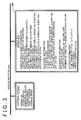
- FIG. 3 is a diagram showing an example of record items that are recorded and retained by the data recording/retaining process portion 14.
- the data recording/retaining process portion 14 generates by itself various pieces of information as shown in FIG. 3 (details thereof will be described later as needed), or acquires pieces of information from external systems via a vehicle-mounted LAN (CAN (controller area network), or the like), and stores and retains the generated or acquired pieces of information in a non-volatile memory 70.
- the non-volatile memory 70 may be any kind of non-volatile memory, for example, an EEPROM, a hard disk, etc.
- the information acquired from external systems include, for example, brake operation information from a brake switch (or a brake stroke sensor for detecting the amount of brake operation, a master cylinder pressure sensor), an engine rotation speed information from an engine ECU (engine rotation speed sensor), shift position information (or gear speed information) from a shift position sensor, vehicle speed information from wheel speed sensors, and accelerator operation amount information from an accelerator operation amount sensor, as shown in FIG. 3 .
- the data recording/retaining process portion 14 records and retains different pieces of information in accordance with the crash forms detected by the activation control portion 12.
- EDR Event Data Recorder
- the output data (Tnx) of the floor sensor 30, of all the sensor information is set as a record item for the front crash.
- the output data of the left/right B/C pillar sensors 40 on the crash side e.g., LBpy, LCpy in the case of a leftward side crash
- the output data (Tny) of the floor sensor 30, of all the sensor information are set as record items.
- the output data (RR) of the roll rate sensor 50 and the output data (GY) of the floor sensor 30, of all the sensor information are set as record items.
- the airbag deployment information is information regarding the airbags and the like that are activated.
- the on-duration and the deployment output of the front impact airbag, and the on-duration and the seat belt tension of the front impact pretensioner are set as record items.
- the on-duration and the deployment output of the side impact airbag, and the on-duration and the deployment output of the side impact curtain shield airbag are set as record items.
- the on-duration and the deployment output of the rollover curtain shield airbag are set as record items.
- the on-duration refers to a duration from the generation of a TRG signal (described later) to the generation of an airbag activation signal.
- the information recorded and retained by the data recording/retaining process portion 14 is not limited to the foregoing information, but that the invention is applicable no matter what information is recorded and retained.
- each TRG signal is a signal that informs of a data record start timing, and is generated in the activation control portion 12.
- the activation control portion 12 generates different TRG signals in accordance with the crash forms.
- the TRG signals include a TRG signal concerning the front crash (hereinafter, referred to as “front crash TRG”), a TRG signal concerning the side crash (hereinafter, referred to as “side crash TRG”), and a TRG signal concerning the rollover (hereinafter, referred to as "rollover TRG").
- front crash TRG a TRG signal concerning the front crash
- side crash TRG a TRG signal concerning the side crash
- rollover TRG a TRG signal concerning the rollover
- Each of these TRG signals is generated at latest before a corresponding one of the crash forms is detected, that is, before an activation signal for a corresponding one of the occupant protection devices is generated.
- the activation control portion 12 may generate a TRG signal concerning the form of the ongoing crash when the sensor output for use for the foregoing determination regarding activation exceeds a threshold value that is smaller than the threshold value used for the foregoing determination regarding activation.
- an appropriate threshold value (threshold for TRG) that is smaller (better in sensitivity) than the threshold value set for activation determination may be set for the impact value based on the output value of the front sensor 20.
- the front crash TRG may be generated when the impact value becomes greater than the threshold value set for the TRG.
- an appropriate threshold value (threshold value set for TRG) smaller than the threshold value set for activation determination may be set for the impact value based on the output value of the floor sensor 30 and the left/right B/C pillar sensors 40.
- the side crash TRG may be generated when the impact value becomes greater than the threshold value set for TRG.
- an appropriate threshold value (threshold value set for TRG) smaller than the threshold value set for determination of rollover may be set.
- the rollover TRG may be generated when, for example, the roll rate RR or the lateral acceleration GY becomes greater than the threshold value set for TRG.
- condition for generating a TRG signal is not limited to the foregoing conditions, but that the invention is applicable for any condition for TRG signal generation as long as the TRG signal is generated in an appropriate state prior to the fulfillment of the activating condition for the occupant protection device.
- the data recording/retaining process portion 14 records and retains pre-crash data provided within a predetermined period before the TRG generation as shown in FIG. 5 .
- the pre-crash data is acquired from external systems mentioned above, and is related to the accelerator operation amount, the engine rotation speed, the vehicle speed, and the brake state.
- the data is stored in the RAM at predetermined sampling intervals ⁇ T1 as shown in FIG. 5 .
- a predetermined sampling number of data preceding the TRG generation, of all the data stored in the RAM are read from the RAM, and are written (recorded and retained) into the memory 70. This makes it possible to posteriorly grasp various states of the vehicle occurring immediately before a crash form occurs, by posteriorly analyzing the data retained in the memory 70.
- the data recording/retaining process portion 14 writes (stores and retains) occupant information obtained at the time of TRG generation (which may be slightly before and after TRG generation) into the memory 70 as shown in FIG. 5 .
- the occupant information may include, as also shown in FIG. 3 , the on/off information regarding buckle switches (i.e., information as to whether or not the seat belt is fastened), the seat position of the driver seat, the occupant detecting sensor information regarding the passenger seats (i.e., information as to whether or not there is any occupant besides the driver), the on/off information regarding the manual cut switch of each passenger seat front impact airbag, the on/off information regarding the manual cut switch of each curtain shield airbag, etc.
- the on/off information regarding buckle switches i.e., information as to whether or not the seat belt is fastened
- the occupant detecting sensor information regarding the passenger seats i.e., information as to whether or not there is any occupant besides the driver
- psychological state-indicating information may also be stored and retained as occupant information.
- data obtained during a predetermined period preceding the occurrence of a crash form may be stored and retained, similarly to the aforementioned pre-crash data, so as to allow posterior analysis of the psychological state (psychological changes and the like) of the driver preceding the occurrence of the crash form.
- the data recording/retaining process portion 14 writes (stores and retains) diagnostic information into the memory 70 at the time of TRG occurrence (which may be slightly before or after TRG generation) as shown in FIG. 5 .
- the diagnostic information may include, as also shown in FIG. 3 , various diagnostic codes, the number of times of ignition switch being on (IG being on) during a failure, the light-on duration of a failure indicator lamp, etc.
- the data recording/retaining process portion 14, as shown in FIG. 5 acquires sensor information in accordance with the kind of TRG signal (front crash TRG, side crash TRG, rollover TRG) as mentioned above on a predetermined sampling cycle ⁇ T2 and a predetermined length of recording time (see FIG. 8 ) after TRG generation, and writes (stores and retains) the information as post-crash data into the memory 70.
- This writing process is, in principle, executed in every sampling cycle ⁇ T2 by a one-by-one write-in method.
- the sampling cycle ⁇ T2 and the recording time length are appropriately determined in accordance with the characteristic of the crash form (i.e., the kind of TRG), and it is preferable that the sampling cycle ⁇ T2 be set shorter than the sampling cycle ⁇ T1. This is mainly because the post-crash data has greater changes over time than the pre-crash data. This makes it possible to efficiently record the most important data and minimize the data shortage resulting from the vehicle electric power down.
- the data recording/retaining process portion 14 similarly writes (stores and retains) into the memory 70 airbag deployment information concerning the activated airbag device. This makes it possible to posteriorly grasp whether or not the airbags concerned were properly activated, by posteriorly analyzing the data retained in the memory 70.
- the data recording/retaining process portion 14, as shown in FIG. 5 writes (stores and retains) system information into the memory 70 following TRG generation.
- the system information may include, as also shown in FIG. 3 , time parameters (described later with reference to FIG. 8 ), and may also include a write completion flag, a freeze signal, etc.
- the write completion flag is set at the time point of the end of the recording/retaining of the aforementioned post-crash data with a predetermined recording time length.
- this embodiment recording processes corresponding to the various TRGs are executed, so that appropriate information corresponding to the various crash forms can be recorded for posterior analysis.
- This recording method does not pose a problem if a crash form singly occurs.
- this embodiment provides a data recording/retaining process that makes it possible to write proper information efficiently into the memory 70 in the case where two or more crash forms continually occur in proximity in time.
- FIG. 6 is a flowchart showing an embodiment of a data recording/retaining process executed by the data recording/retaining process portion 14. When the ignition switch of the vehicle is turned on, the process of this flowchart is repeatedly executed.
- step S100 the presence/absence of generation of a TRG signal is determined. If a TRG signal is generated (in the case of "YES"), the process shifts to step S110, S120 or S130 corresponding to the kind of TRG, and the data recording/retaining process starts to be performed in accordance with the various TRGs. If the determination of "NO" is made at step S100, the process of this flowchart is ended.
- step S220 the recording process is continued (step S220) until the recording process ends (YES at step S230).
- step S230 it is determined whether or not the side crash TRG or the rollover TRG is generated (step S200). Regardless of the result of the determination, the post-crash data as well as the pre-crash data is recorded for a predetermined recording time length as long as there is not a vehicle electric power down.
- a write completion flag is set.
- the time amount Ta or Tb (a time parameter of the system information, shown in FIGS. 3 and 8 ) between the time of generation of the front crash TRG and the time of generation of the side crash TRG or rollover TRG is computed, and the computed time amount Ta or Tb is written into the memory 70 (step S210).
- step S330 the front crash TRG is generated (YES at step S300)
- the time amount between the time of generation of the side crash TRG and the time of generation of the front crash TRG is computed, and is written into the memory 70 (step S310). After that, the process from step S110 onward is executed.
- the recording process concerning the side crash TRG is interrupted, and the record items corresponding to the front crash are preferentially recorded.
- the occupant information and the diagnostic information, which were recorded in step S120 are not written into the memory 70, so that waste due to redundancy is avoided.
- the recording process concerning the side crash TRG is temporarily interrupted. Then, when the preferential recording process for the record items corresponding to the front crash ends (YES at step S230), the recording process for the side crash is resumed and continued (step S320). It is to be noted herein that even during the interruption of the process of recording into the memory 70 in relation to the side crash TRG, the record items for the side crash are written into the RAM. Therefore, at the time of resumption, the data (e.g., sensor information) stored in the RAM during the interruption is read therefrom with reference to the write-in address in the RAM used immediately prior to the interruption, and is written into the memory 70 in batch. From then on, the sensor information acquired on the sampling cycle ⁇ T2, and the like, is written in a one-by-one fashion in accordance with needs.
- the data e.g., sensor information
- step S430 it is monitored and determined whether or not the front crash TRG is generated, until the recording process ends (YES at step S430). If the front crash TRG is generated (YES at step S400), the time amount between the time of generation of the rollover TRG and the time of generation of the front crash TRG is computed, and is written into the memory 70 (step S410). After that, the process from step S110 onward is executed.
- step S110 following the process shift, the occupant information and the diagnostic information, which were recorded in step S130, are not written into the memory 70, so that waste due to redundancy is avoided.
- the recording process concerning the rollover crash TRG is temporarily interrupted. Then, after the preferential recording process for the record items corresponding to the front crash has ended (YES at step S230), and after, if a side crash occurred prior to that moment, the recording process for the record items corresponding to the side crash has ended (NO at step S240), the recording process for the rollover is resumed and continued (step S420). It is to be noted herein that even during the interruption of the process of recording into the memory 70 in relation to the rollover TRG, the record items for the rollover are written into the RAM.
- the data (e.g., sensor information) stored in the RAM during the interruption is read therefrom with reference to the write-in address in the RAM used immediately prior to the interruption, and is written into the memory 70 in batch. From then on, the sensor information acquired on the sampling cycle ⁇ T2, and the like, is written in a one-by-one fashion in accordance with needs.
- the recording process concerning the front crash TRG is preferentially executed regardless of their sequence in time. Therefore, if the front crash TRG is first generated and then the side crash TRG or the rollover TRG is immediately generated, the record items corresponding to the front crash are continuously recorded until the recording is completed. In this manner, the recording process reshold value set for activation determination may be set for the impact value bsequent generation of the side crash TRG or the rollover TRG.
- the record items corresponding to the front crash are preferentially recorded.
- Reasons for this are as follows. In the case of the front crash, compared with the other crash forms, the amount of deformation/intrusion of the engine compartment is large, and the possibility of vehicle electric power down is also high since the battery 110 is disposed in the engine compartment. If the recording process concerning any other crash form is given priority, it can become impossible to record and recover the record data concerning the front crash, which is the most important and useful, due to a vehicle electric power down that may well occur at the time of a front crash.
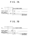
- FIGS. 7A and 7B are diagrams showing results of recording in the case where vehicle electric power down occurs during a recording/retaining process.
- FIG. 7A shows results of recording in the embodiment
- FIG. 7B shows ordinary results of recording in the case where the recording process for the front crash TRG is not given priority over the recording process for the other crash forms.
- the results of recording shown in both FIGS. 7A and 7B are those obtained in the case where the side crash TRG or the rollover TRG is first generated and then the front crash TRG is immediately generated.
- the recording process for the front crash is given priority over the recording processes for the other crash forms, the recording of the record items concerning the front crash can be recoverably carried out at least until immediately before the vehicle electric power down (see the position of fall of +B) if the power down happens after the occurrence of the front crash. In this case, it is impossible, however, to recoverably carry out the recording of the record items concerning the side crash or the rollover until immediately before the vehicle electric power down (in some cases, a portion of the recording prior to the interruption is recoverable). However, since the record data concerning the front crash which is most importance and useful is recorded recoverably, the influence of the vehicle electric power down on the posterior analysis can be minimized.
- a construction is made such that if the side crash TRG or the rollover TRG is generated first in time and then the front crash TRG is immediately generated, the record items concerning the front crash are subjected to the recording process preferentially over the record items concerning the side crash or rollover. Therefore, it becomes possible to reliably recover the recording of the record items concerning the front crash which are the most important and useful in the posterior analysis.
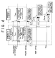
- FIG. 8 is a diagram showing in time series an example of system information as well as a data recording fashion according to the embodiment as shown in the flowchart of FIG. 6 .
- the aforementioned various record items are recorded in correspondence to events in which the record items were acquired. That is, in the example shown in FIG. 8 , only the front crash TRG was generated in the previous event N-1, and the record items (occupant information, and the like) were recorded in correspondence to the event number N-1.
- the front crash TRG is followed by the occurrence of the side crash TRG and the occurrence of the rollover TRG, and the record items (occupant information, and the like) are recorded in correspondence to the event number N.
- an event refers to a basic unit that can be separated as a crash phenomenon and, in some cases, a plurality of crash forms can occur continually during one event. Therefore, even the case where the generation of the first TRG is followed by the generation of another TRG within a predetermined short time T_pre [ms] is considered as a single event by the data recording/retaining process portion 14. As described above, if another TRG is generated before the time T_pre elapses following the occurrence of the first TRG, the recording of occupant information and the like in response to the another TRG is prohibited so as to eliminate redundancy and save memory capacity. More specifically, the recording of occupant information and diagnostic data is prohibited.
- various pieces of information are recorded in correspondence to the events in which the pieces of information are acquired. Therefore, even if data has been recorded over a plurality of events, it is clear in which of the events a piece of information was acquired, so that the posterior analysis becomes easy.
- the time interval between the times of the first TRG generation in the individual events that is, the event interval Tevt [ms]
- the event interval Tevt [ms] is computed (measured), and is recorded and retained as system information (time parameter). Therefore, it is clear at what time interval two or more events occurred, so that the posterior analysis becomes easy.
- TRGs crash forms
- the numbers (serial numbers) EVT_* assigned thereto in accordance with the sequence of generation are recorded and retained as system information.
- number EVT_m-1 (meaning the m-1th in sequence) is assigned to the front crash TRG of the event N-1; number EVT_m is assigned to the front crash TRG of the event N; number EVT_m+1 is assigned to the side crash TRG of the event N; and number EVT_m+2 is assigned to the rollover TRG of the event N.
- serial numbers EVT_* are redundant pieces of information with respect to the other pieces of system information Ta, Tb, and are recorded for improvement in data precision.
- the side crash may be given priority in that case on the basis of a concept similar to the relationship between the front crash TRG and the side crash TRG or the rollover TRG; or the recording may be performed by a FIFO (first-in, first-out) method.
- FIFO first-in, first-out
- the data relevant to a crash low in the order of priority is recorded after completion of the recording of the data relevant to a crash high in the order of priority.
- the recording of the data relevant to a crash low in the order of priority may be omitted after completion of the recording of the data relevant to a crash high in the order of priority.
Description
- The invention relates to a vehicular data recording apparatus that includes crash detection means for detecting a crash of a vehicle, and recording process means for recording and retaining output data of various vehicle-mounted sensors mounted in the vehicle, wherein if a crash is detected by the crash detection means, a data recording/retaining process relevant to the crash is performed by the recording process means.
- Conventionally, a vehicular data recording apparatus that includes record means for recording outputs of various vehicle-mounted sensors mounted in a vehicle, and crash detection means for detecting a crash of the vehicle, and that records and retains vehicle-mounted sensor outputs provided before and after a crash of the vehicle, the vehicular data recording apparatus being characterized by including behavioral sudden change detection means for detecting a sudden change in the vehicle behavior, and record retention control means for, if a crash of the vehicle is detected by the crash detection means, performing a record retention control in a crash mode so as to retain output records provided by vehicle behavior-relevant sensors among the vehicle-mounted sensors during a predetermined period before and after the crash, and for, if a sudden change in the vehicle behavior is detected by the behavioral sudden change detection means, performing a record retention control in a behavioral sudden change mode so as to retain output records provided by vehicle behavior-relevant sensors among the vehicle-mounted sensors during a predetermined period after the behavioral sudden change, has been known (e.g., Japanese Patent Application Publication No.
JP-A-07-277230 - In some cases of actual crashes of vehicles, a plurality of crashes, including a secondary crash, occur in proximity in time; for example, a front crash is followed by occurrence of a side crash and a rollover. However, in the related art, the case where a plurality of crashes occur in proximity in time is not assumed. Furthermore, for example, record retention can become impossible due to disconnection of a battery prior to a batch write-in process, and data concerning the initial crash can be overwritten by data concerning a later crash in some cases. Therefore, there is possibility that necessary data may not be recorded and unnecessary data may be recorded. Thus, there is a problem of being unable to reliably and efficiently record and retain data that is necessary and sufficient for analysis of causes of the crash, and the like.
- Document
US 4,638,289 B discloses an accident data recorder according to the preamble ofindependent claim 1 of the present invention. DocumentEP 0 847 029 A2 discloses a method for storing data relevant to an accident according to the preamble of independent claim 11 of the present invention. - Accordingly, it is an object of the invention to provided a vehicular data recording apparatus capable of reliably and efficiently recording and retaining data that is necessary and sufficient for analysis of causes of a crash, and the like.
- To achieve the aforementioned object, a vehicular data recording apparatus in a first aspect of the invention, which includes crash detection means for detecting a crash of a vehicle, and recording process means for recording and retaining output data of various vehicle-mounted sensors mounted in the vehicle, in a non-volatile memory. If a crash is detected by the crash detection means, a data recording/retaining process relevant to the crash is performed by the recording process means. If a plurality of crashes different in crash form are detected continually in a short time by the crash detection means, the recording process means performs the data recording/retaining process relevant to each crash in accordance with a predetermined order of priority of each crash form. If, during the data recording/retaining process relevant to a first crash following detection of the first crash, a second crash higher in the order of priority than the first crash is detected by the crash detection means, the recording process means interrupts the data recording/retaining process relevant to the first crash, and performs the data recording/retaining process relevant to the second crash.
- In the foregoing first aspect, the crash forms detected by the crash detection means may include a front crash, a side crash, and a rollover, and the front crash may be given a higher order of priority than the side crash and the rollover.
- Furthermore, in the first aspect, a high order of priority may be given to a crash that is highly likely to interfere with a mounting position of the recording process means, or a mounting position of a battery that serves as an electric power source for a recording/retaining operation of the recording process means.
- In the foregoing aspect, during an interruption of the data recording/retaining process of data relevant to the first crash, the data relevant to the first crash may be stored into a RAM. Furthermore, after the data recording/retaining process of the crash high in the order of priority is completed, the recording process means may perform writing of the data relevant to the crash low in the order of priority written in the RAM, into the non-volatile memory, and the data recording/retaining process.
- In the foregoing aspect, the recording process means may perform the data recording/retaining process regarding the crash high in the order of priority, by a one-by-one write-in method.
- In the first aspect, the recording process means may perform the data recording/retaining process relevant to the crash low in the order of priority after completing the data recording/retaining process relevant to the crash high in the order of priority.
- In the first aspect, the crash detection means may perform detection of a crash, and determination of a crash form based on an output value of the various vehicle-mounted sensors mounted in the vehicle.
- In the first aspect, data recorded and retained by the recording process means after a crash is detected by the crash detection means includes at least one of on/off information regarding a buckle switch, occupant detecting sensor information, on/off information regarding a manual cut switch of an airbag, a diagnostic code, a number of times of IG being on during a failure, a light-on duration of a failure lamp, a time parameter, a write completion flag, and a freeze signal.
- The data recorded and retained by the recording process means may further include at least one of brake operation information, engine rotation speed information, shift position information, a vehicle speed, and an accelerator operation amount.
- In the first aspect, if a crash is detected by the crash detection means, the recording process means may record and retain relevant information that indicates a state of an occupant and/or a state of the vehicle occurring at a time of detection of the crash or in a predetermined time preceding the time of detection of the crash, together with the output data of a predetermined vehicle-mounted sensor following the crash.
- A method of performing data recording/retention relevant to a crash of a vehicle in the invention includes detecting a crash of the vehicle, and recording and retaining output data of various vehicle-mounted sensors mounted in the vehicle, in a non-volatile memory. If a plurality of crashes different in crash form are detected continually in a short time, a data recording/retaining process relevant to each crash is performed in the recording and retaining step in accordance with a predetermined order of priority of each crash form.
- Furthermore, since the data recording/retaining process relevant to each crash is performed in accordance with the order of priority based on the crash form of each crash, the apparatus of the invention is able to reliably and efficiently record and retain data that is necessary and sufficient for analysis of causes of a crash, and the like.
- The foregoing and/or further objects, features and advantages of the invention will become more apparent from the following description of preferred embodiment with reference to the accompanying drawings, in which like numerals are used to represent like elements and wherein:
-
FIG. 1 is a system construction diagram showing an embodiment of the vehicular data recording apparatus of the invention; -
FIG. 2 is a schematic plan view showing an embodiment of various sensors mounted in a vehicle; -
FIG. 3 is a diagram showing an example of record items that are recorded and retained by a data recording/retaining process portion 14; -
FIG. 4 is a diagram showing an example of record items related to sensor information related to the crash form; -
FIG. 5 is a timing chart schematically showing a data recording/retaining process executed by the data recording/retaining process portion 14 in the embodiment; -
FIG. 6 is a flowchart showing a characteristic data recording/retaining process executed by the data recording/retaining process portion 14 in the embodiment; -
FIGS. 7A and 7B are diagrams showing results of recording in the case where a vehicle electric power down occurs during a recording/retaining process; and -
FIG. 8 is a diagram showing in time series an example of system information as well as a data recording fashion according to the embodiment. - Hereinafter, example embodiments of the invention will be described with reference to accompanying drawings.
-
FIG. 1 is a system construction diagram showing an embodiment of the vehicular data recording apparatus of the invention. A vehicular data recording apparatus of this embodiment is embodied by anairbag ECU 100 that performs a control of activating a vehicle occupant protection device, such as an airbag and the like. However, the construction and functions of a vehicular data recording apparatus described below may be packaged in an ECU other than theairbag ECU 100, or may also be realized through cooperation of a plurality of ECUs. - The airbag ECU 100 operates using as an electric power source a
battery 110 mounted in a vehicle. Thebattery 110 is typically disposed in an engine compartment positioned forward in the vehicle. - The occupant protection device may include airbags of seats for front impact (hereinafter, referred to as "front impact airbags"), seat belt pretensioners of seats for front impact (hereinafter, referred to as "front impact pretensioners"), side airbags for side impact (hereinafter, referred to as "side impact airbags"), curtain shield airbags for side impact or rollover (hereinafter, referred to as "side impact curtain shield airbags or rollover curtain shield airbags"), and may further include various other occupant protection devices, such as headrest airbags for rear seats, knee airbags of the driver and navigator seats for protecting occupant's knee portions, etc. Each occupant protection device is activated by an ignition device (squib) that is provided for causing generation of gas from an inflator and thereby instantaneously inflating the airbag, or the like.
- Each occupant protection device may be an occupant protection device whose output level (protection performance) is variable, including, for example, various airbags whose deployment output is variable, a belt tension variable mechanism, etc. For brief reference to the airbags, as for example, the output level of airbags, that is, the deployment output (pressure) for airbags, can be adjusted by changing the number of inflators to be actuated among a plurality of inflators, or by changing the actuating timing of a plurality of inflators. In this case, the output level of the occupant protection device is determined in the
airbag ECU 100. - The
airbag ECU 100 is constructed of a microcomputer, and has, for example, a CPU, a ROM that stores control programs, a readable/writable RAM for storing results of computation and the like, a timer, a counter, an input interface, an output interface, etc. - As shown in
FIG. 1 , theairbag ECU 100 includes anactivation control portion 12 and the data recording/retaining process portion 14 of the occupant protection devices. It is to be noted herein that theactivation control portion 12 and the data recording/retaining process portion 14 in this embodiment correspond to the crash detection means and the recording process means in the invention. - The
activation control portion 12 is detecting various crash forms for which the occupant protection device is designed to become activated, and performing a control of activating the occupant protection device on the basis of a relationship between the output information of the various sensors (seeFIG. 2 ) mounted in the vehicle and a given activation determining condition. The various crash forms detected by theactivation control portion 12 include, for example, front crashes (including head-on crashes, oblique crashes, pole crashes, etc.), side crashes (including right-side front seat crashes, left-side front seat crashes, right-side rear seat crashes, left-side rear seat crashes, etc.), and rollovers (right-side rollovers, left-side rollovers). Besides these, rear crashes may also be included. -
FIG. 2 is a schematic plan view of a vehicle showing an embodiment of various sensors (sensing system) mounted in the vehicle. In the embodiment shown inFIG. 2 ,front sensors 20 and afloor sensor 30 are shown as sensors for detecting a front crash. Thefront sensors 20 are single-axis acceleration sensors, and are mounted in right and left side portions of a front portion of the vehicle. As shown inFIG. 2 , thefront sensors 20 detect the accelerations RFrx, LFrx in the longitudinal directions of the vehicle, respectively, which act on their mounting positions. Thefloor sensor 30 is a two-axis acceleration sensor mounted in a central portion of the vehicle (e.g., in a floor tunnel near a central console of the vehicle). As a front crash detecting sensor, thefloor sensor 30 detects the acceleration Tnx that acts on the mounting position in the longitudinal directions of the vehicle as shown inFIG. 2 . Incidentally, thefloor sensor 30 may be provided in a controller unit that includes theairbag ECU 100. - On the basis of the output value of the
floor sensor 30, theactivation control portion 12 computes an impact value (e.g., a value obtained through a predetermined filter process of the sensor signal, a value obtained through time integration of the sensor signal, a value obtained by integrating the sensor signal twice with respect to time). On the basis of a relationship between the computed impact value and a predetermined threshold value, theactivation control portion 12 determines whether or not to activate the front impact airbags and the front impact pretensioners (hereinafter, represented by the "front impact airbags" for convenience). If the computed impact value exceeds the threshold value and therefore it is determined that the front impact airbags should be activated, an activation signal is sent out to an actuator device of the front impact airbags, whereby the activation of the front impact airbags is realized. On this occasion, a deployment output corresponding to the impact value may be instructed. The aforementioned threshold value may be variable on the basis of the impact value detected by thefront sensors 20. This enables early activation determination for a front crash, and also enables activation determination factoring in the differences among the crash forms. - Furthermore in the embodiment shown in
FIG. 2 , left and right B/C pillar sensors 40 are provided as side impact detecting sensors, in addition to thefloor sensor 30. Thefloor sensor 30 as a side impact detecting sensor detects the acceleration Tny in the vehicle lateral direction which acts on its mounting position as shown inFIG. 2 . The left and right B/C pillar sensors 40 are disposed on left and right B and C pillars, respectively, and detect accelerations LBpy, RBpy, LCpy, RCpy that act on their mounting positions in the lateral directions of the vehicle as shown inFIG. 2 . - Similarly, on the basis of the output values of the left and right B/
C pillar sensors 40 and the output value of thefloor sensor 30, theactivation control portion 12 computes an impact value. On the basis of a relationship between the computed impact value and a predetermined threshold value, it is determined whether or not to activate the occupant protection device (e.g., side impact airbags, and side impact curtain shield airbags, which will be represented by the "side impact airbags" for convenience). If the computed impact value exceeds the threshold value and therefore it is determined that the side impact airbag should be activated, an activation signal is sent out to the actuator device of the side impact airbags, whereby actuation of the side impact airbags is realized. Incidentally, the side impact airbag to be activated at the time of determining that the side crash is going on is selected in accordance with various manners of side crash, that is, the right-side front seat crash, the left-side front seat crash, the right-side rear seat crash, the left-side rear seat crash, etc. Incidentally, as in the case of front crashes, it is possible to make a determination regarding the activation on the basis of the output value of thefloor sensor 30 and a predetermined threshold value, and to use the output values of the left and right B/C pillar sensors 40 for varying the predetermined threshold value. - Still further, in the embodiment shown in
FIG. 2 , aroll rate sensor 50 is provided as a rollover detecting sensor, in addition to thefloor sensor 30. Theactivation control portion 12 determines whether or not to activate rollover curtain shield airbags on the basis of the roll rate RR detected by the roll rate sensor 50 (and/or the roll angle RA, that is, an integral value of the roll rate RR), and the lateral acceleration GY detected by thefloor sensor 30. On this occasion, determination regarding rollover may also be realized through the use of a map for rollover determination based on a relationship between the roll rate and the roll angle, and another map for rollover determination based on a relationship between the roll rate and the lateral acceleration. Likewise, for example, if the roll rate RR exceeds a threshold value for the determination regarding rollover and therefore it is determined that the rollover curtain shield airbag should be activated, an activation signal is sent out to the actuator device of the rollover curtain shield airbags, whereby activation of the rollover curtain shield airbag is realized. - Incidentally, it should be apparent that the method of detection/determination of the various crash forms is not limited to the above-described method, but that the invention is applicable to any one of such methods of detection/determination. Furthermore, in the method of detection/determination of the various crash forms, it is possible to cooperatively use results of detection regarding obstacles around the vehicle, which are provided by a radar sensor and an image sensor.
- The data recording/
retaining process portion 14 performs a recording/retaining process on various data relevant to a crash so as to allow posterior analysis of the event (analysis of the causes of the crash and the situation of the vehicle before and after the crash, the situation of activation of the occupant protection device, etc.). -
FIG. 3 is a diagram showing an example of record items that are recorded and retained by the data recording/retaining process portion 14. InFIG. 3 , the various record items are shown in association with the source of acquisition/generation of the information, for convenience. The data recording/retaining process portion 14 generates by itself various pieces of information as shown inFIG. 3 (details thereof will be described later as needed), or acquires pieces of information from external systems via a vehicle-mounted LAN (CAN (controller area network), or the like), and stores and retains the generated or acquired pieces of information in anon-volatile memory 70. Thenon-volatile memory 70 may be any kind of non-volatile memory, for example, an EEPROM, a hard disk, etc. The information acquired from external systems include, for example, brake operation information from a brake switch (or a brake stroke sensor for detecting the amount of brake operation, a master cylinder pressure sensor), an engine rotation speed information from an engine ECU (engine rotation speed sensor), shift position information (or gear speed information) from a shift position sensor, vehicle speed information from wheel speed sensors, and accelerator operation amount information from an accelerator operation amount sensor, as shown inFIG. 3 . - The data recording/
retaining process portion 14 records and retains different pieces of information in accordance with the crash forms detected by theactivation control portion 12. For example, as indicated by circles in the column of "EDR (Event Data Recorder) record", the output data (Tnx) of thefloor sensor 30, of all the sensor information, is set as a record item for the front crash. For the side crash, the output data of the left/right B/C pillar sensors 40 on the crash side (e.g., LBpy, LCpy in the case of a leftward side crash), and the output data (Tny) of thefloor sensor 30, of all the sensor information, are set as record items. For the rollover, the output data (RR) of theroll rate sensor 50 and the output data (GY) of thefloor sensor 30, of all the sensor information, are set as record items. - As for the airbag deployment information, too, different pieces of information are recorded and retained in accordance with different crash forms since the airbag deployment information is information regarding the airbags and the like that are activated. For example, for the front crash, the on-duration and the deployment output of the front impact airbag, and the on-duration and the seat belt tension of the front impact pretensioner are set as record items. For the side crash, the on-duration and the deployment output of the side impact airbag, and the on-duration and the deployment output of the side impact curtain shield airbag are set as record items. For the rollover, the on-duration and the deployment output of the rollover curtain shield airbag are set as record items. Incidentally, the on-duration refers to a duration from the generation of a TRG signal (described later) to the generation of an airbag activation signal.
- It should be apparent that the information recorded and retained by the data recording/
retaining process portion 14 is not limited to the foregoing information, but that the invention is applicable no matter what information is recorded and retained. - Next, with reference to
FIG. 5 , a data recording/retaining process executed in the data recording/retaining process portion 14 will be briefly described. The data recording/retaining process in the data recording/retaining process portion 14 is triggered by the generation of various TRG signals allowed under a predetermined condition for the generation. That is, each TRG signal is a signal that informs of a data record start timing, and is generated in theactivation control portion 12. Theactivation control portion 12 generates different TRG signals in accordance with the crash forms. That is, the TRG signals include a TRG signal concerning the front crash (hereinafter, referred to as "front crash TRG"), a TRG signal concerning the side crash (hereinafter, referred to as "side crash TRG"), and a TRG signal concerning the rollover (hereinafter, referred to as "rollover TRG"). Each of these TRG signals is generated at latest before a corresponding one of the crash forms is detected, that is, before an activation signal for a corresponding one of the occupant protection devices is generated. For example, theactivation control portion 12 may generate a TRG signal concerning the form of the ongoing crash when the sensor output for use for the foregoing determination regarding activation exceeds a threshold value that is smaller than the threshold value used for the foregoing determination regarding activation. Specifically, with regard to the front crash TRG, an appropriate threshold value (threshold for TRG) that is smaller (better in sensitivity) than the threshold value set for activation determination may be set for the impact value based on the output value of thefront sensor 20. The front crash TRG may be generated when the impact value becomes greater than the threshold value set for the TRG. Likewise, with regard to the side crash TRG, an appropriate threshold value (threshold value set for TRG) smaller than the threshold value set for activation determination may be set for the impact value based on the output value of thefloor sensor 30 and the left/right B/C pillar sensors 40. The side crash TRG may be generated when the impact value becomes greater than the threshold value set for TRG. Furthermore, likewise, with reference to the rollover TRG, an appropriate threshold value (threshold value set for TRG) smaller than the threshold value set for determination of rollover may be set. The rollover TRG may be generated when, for example, the roll rate RR or the lateral acceleration GY becomes greater than the threshold value set for TRG. - It should be apparent that the condition for generating a TRG signal is not limited to the foregoing conditions, but that the invention is applicable for any condition for TRG signal generation as long as the TRG signal is generated in an appropriate state prior to the fulfillment of the activating condition for the occupant protection device.
- As described above, when a TRG signal is generated, the data recording/
retaining process portion 14 records and retains pre-crash data provided within a predetermined period before the TRG generation as shown inFIG. 5 . The pre-crash data is acquired from external systems mentioned above, and is related to the accelerator operation amount, the engine rotation speed, the vehicle speed, and the brake state. The data is stored in the RAM at predetermined sampling intervals ΔT1 as shown inFIG. 5 . At the time of TRG generation, a predetermined sampling number of data preceding the TRG generation, of all the data stored in the RAM, are read from the RAM, and are written (recorded and retained) into thememory 70. This makes it possible to posteriorly grasp various states of the vehicle occurring immediately before a crash form occurs, by posteriorly analyzing the data retained in thememory 70. - Furthermore, the data recording/
retaining process portion 14 writes (stores and retains) occupant information obtained at the time of TRG generation (which may be slightly before and after TRG generation) into thememory 70 as shown inFIG. 5 . The occupant information may include, as also shown inFIG. 3 , the on/off information regarding buckle switches (i.e., information as to whether or not the seat belt is fastened), the seat position of the driver seat, the occupant detecting sensor information regarding the passenger seats (i.e., information as to whether or not there is any occupant besides the driver), the on/off information regarding the manual cut switch of each passenger seat front impact airbag, the on/off information regarding the manual cut switch of each curtain shield airbag, etc. This makes it possible to posteriorly grasp the posture of each occupant, the state of occupant restraint achieved by the seat belts, and the setting of the various airbags, by posteriorly analyzing the data retained in thememory 70. From a similar standpoint, images of the occupants (particularly, images showing the orientation of the driver's face, and the like) taken by an in-vehicle camera may be stored and retained as occupant information, if such a camera is provided. Furthermore, if information useful for grasping the psychological state of the occupants (particularly, the driver), for example, voice data that can be picked up via an in-vehicle microphone, biological data, such as a pulse rate and the like, by a biological sensor embedded in the steering wheel or the like, etc., can be acquired, such psychological state-indicating information may also be stored and retained as occupant information. As for the psychological state-indicating information, data obtained during a predetermined period preceding the occurrence of a crash form may be stored and retained, similarly to the aforementioned pre-crash data, so as to allow posterior analysis of the psychological state (psychological changes and the like) of the driver preceding the occurrence of the crash form. - Furthermore, the data recording/
retaining process portion 14 writes (stores and retains) diagnostic information into thememory 70 at the time of TRG occurrence (which may be slightly before or after TRG generation) as shown inFIG. 5 . The diagnostic information may include, as also shown inFIG. 3 , various diagnostic codes, the number of times of ignition switch being on (IG being on) during a failure, the light-on duration of a failure indicator lamp, etc. - Still further, the data recording/
retaining process portion 14, as shown inFIG. 5 , acquires sensor information in accordance with the kind of TRG signal (front crash TRG, side crash TRG, rollover TRG) as mentioned above on a predetermined sampling cycle ΔT2 and a predetermined length of recording time (seeFIG. 8 ) after TRG generation, and writes (stores and retains) the information as post-crash data into thememory 70. This writing process is, in principle, executed in every sampling cycle ΔT2 by a one-by-one write-in method. Therefore, even if the occurrence of a crash form is followed by an electric power down of the vehicle (e.g., malfunction of the battery associated with direct impact thereon or deformation of surrounding members) or the like, at least the data obtained up to that moment can be recorded in thememory 70. Incidentally, the sampling cycle ΔT2 and the recording time length are appropriately determined in accordance with the characteristic of the crash form (i.e., the kind of TRG), and it is preferable that the sampling cycle ΔT2 be set shorter than the sampling cycle ΔT1. This is mainly because the post-crash data has greater changes over time than the pre-crash data. This makes it possible to efficiently record the most important data and minimize the data shortage resulting from the vehicle electric power down. - Furthermore, as shown in
FIG. 5 , if activation of any airbag device occurs after the TRG generation, the data recording/retaining process portion 14 similarly writes (stores and retains) into thememory 70 airbag deployment information concerning the activated airbag device. This makes it possible to posteriorly grasp whether or not the airbags concerned were properly activated, by posteriorly analyzing the data retained in thememory 70. - Furthermore, the data recording/
retaining process portion 14, as shown inFIG. 5 , writes (stores and retains) system information into thememory 70 following TRG generation. The system information may include, as also shown inFIG. 3 , time parameters (described later with reference toFIG. 8 ), and may also include a write completion flag, a freeze signal, etc. The write completion flag is set at the time point of the end of the recording/retaining of the aforementioned post-crash data with a predetermined recording time length. - Incidentally, in this embodiment, recording processes corresponding to the various TRGs are executed, so that appropriate information corresponding to the various crash forms can be recorded for posterior analysis. This recording method does not pose a problem if a crash form singly occurs. However, if two or more crash forms continually occur in proximity in time, it is practically difficult to write the record items concerning the crash forms simultaneously (parallelly) into the
memory 70. Therefore, this embodiment provides a data recording/retaining process that makes it possible to write proper information efficiently into thememory 70 in the case where two or more crash forms continually occur in proximity in time. -
FIG. 6 is a flowchart showing an embodiment of a data recording/retaining process executed by the data recording/retaining process portion 14. When the ignition switch of the vehicle is turned on, the process of this flowchart is repeatedly executed. - First, at step S100, the presence/absence of generation of a TRG signal is determined. If a TRG signal is generated (in the case of "YES"), the process shifts to step S110, S120 or S130 corresponding to the kind of TRG, and the data recording/retaining process starts to be performed in accordance with the various TRGs. If the determination of "NO" is made at step S100, the process of this flowchart is ended.
- Hereinafter, description will be made separately for (1) the case where the front crash TRG is generated, (2) the case where the side crash TRG is generated, and (3) the case where the rollover TRG is generated.
- Firstly, in (1) the case where the front crash TRG is generated, the recording process is continued (step S220) until the recording process ends (YES at step S230). During this recording process, it is determined whether or not the side crash TRG or the rollover TRG is generated (step S200). Regardless of the result of the determination, the post-crash data as well as the pre-crash data is recorded for a predetermined recording time length as long as there is not a vehicle electric power down. When the recording is completed (YES at step S230), a write completion flag is set. Thus, in this embodiment, in the case where the front crash TRG is generated initially, a state where the side crash TRG and rollover TRG are invalidated is maintained and the record items corresponding to the front crash TRG are continuously recorded, even if the side crash TRG or the rollover TRG is generated during the recording process (i.e., even if a side crash or a rollover secondarily occurs after the front crash occurs).
- If during the recording process, the side crash TRG or the rollover TRG is generated (YES at step S200), the time amount Ta or Tb (a time parameter of the system information, shown in
FIGS. 3 and8 ) between the time of generation of the front crash TRG and the time of generation of the side crash TRG or rollover TRG is computed, and the computed time amount Ta or Tb is written into the memory 70 (step S210). - On the other hand, in (2) the case where the side crash TRG is generated, it is monitored and determined whether or not the front crash TRG is generated, until the recording process ends (YES at step S330). If the front crash TRG is generated (YES at step S300), the time amount between the time of generation of the side crash TRG and the time of generation of the front crash TRG is computed, and is written into the memory 70 (step S310). After that, the process from step S110 onward is executed. Thus, in the embodiment, if the side crash TRG is initially generated and then the front crash TRG is generated during the recording process (i.e., if after the occurrence of a side crash, a front crash secondarily occurs), the recording process concerning the side crash TRG is interrupted, and the record items corresponding to the front crash are preferentially recorded. In the process of step S110 following the process shift, the occupant information and the diagnostic information, which were recorded in step S120, are not written into the
memory 70, so that waste due to redundancy is avoided. - In the case where the process has shifted to step S110 in the above-described manner, the recording process concerning the side crash TRG is temporarily interrupted. Then, when the preferential recording process for the record items corresponding to the front crash ends (YES at step S230), the recording process for the side crash is resumed and continued (step S320). It is to be noted herein that even during the interruption of the process of recording into the
memory 70 in relation to the side crash TRG, the record items for the side crash are written into the RAM. Therefore, at the time of resumption, the data (e.g., sensor information) stored in the RAM during the interruption is read therefrom with reference to the write-in address in the RAM used immediately prior to the interruption, and is written into thememory 70 in batch. From then on, the sensor information acquired on the sampling cycle ΔT2, and the like, is written in a one-by-one fashion in accordance with needs. - Similarly, in (3) the case where the rollover TRG is generated, it is monitored and determined whether or not the front crash TRG is generated, until the recording process ends (YES at step S430). If the front crash TRG is generated (YES at step S400), the time amount between the time of generation of the rollover TRG and the time of generation of the front crash TRG is computed, and is written into the memory 70 (step S410). After that, the process from step S110 onward is executed. Therefore, in this embodiment, if the rollover TRG is first generated and then the front crash TRG is generated during the recording process (i.e., if after the occurrence of a side crash, a front crash secondarily occurs), the recording process concerning the rollover TRG is interrupted, and the record items corresponding to the front crash TRG are preferentially recorded. In the process of step S110 following the process shift, the occupant information and the diagnostic information, which were recorded in step S130, are not written into the
memory 70, so that waste due to redundancy is avoided. - In the case where the process has shifted to step S110 in the above-described manner, the recording process concerning the rollover crash TRG is temporarily interrupted. Then, after the preferential recording process for the record items corresponding to the front crash has ended (YES at step S230), and after, if a side crash occurred prior to that moment, the recording process for the record items corresponding to the side crash has ended (NO at step S240), the recording process for the rollover is resumed and continued (step S420). It is to be noted herein that even during the interruption of the process of recording into the
memory 70 in relation to the rollover TRG, the record items for the rollover are written into the RAM. Therefore, at the time of resumption, the data (e.g., sensor information) stored in the RAM during the interruption is read therefrom with reference to the write-in address in the RAM used immediately prior to the interruption, and is written into thememory 70 in batch. From then on, the sensor information acquired on the sampling cycle ΔT2, and the like, is written in a one-by-one fashion in accordance with needs. - Thus, in the embodiment, if the front crash TRG and at least one of the side crash TRG and the rollover TRG are generated in proximity in time, the recording process concerning the front crash TRG is preferentially executed regardless of their sequence in time. Therefore, if the front crash TRG is first generated and then the side crash TRG or the rollover TRG is immediately generated, the record items corresponding to the front crash are continuously recorded until the recording is completed. In this manner, the recording process reshold value set for activation determination may be set for the impact value bsequent generation of the side crash TRG or the rollover TRG. On the other hand, if the side crash TRG or the rollover TRG is first generated and then the front crash TRG is immediately generated, the record items corresponding to the front crash are preferentially recorded. Reasons for this are as follows. In the case of the front crash, compared with the other crash forms, the amount of deformation/intrusion of the engine compartment is large, and the possibility of vehicle electric power down is also high since the
battery 110 is disposed in the engine compartment. If the recording process concerning any other crash form is given priority, it can become impossible to record and recover the record data concerning the front crash, which is the most important and useful, due to a vehicle electric power down that may well occur at the time of a front crash. -
FIGS. 7A and 7B are diagrams showing results of recording in the case where vehicle electric power down occurs during a recording/retaining process.FIG. 7A shows results of recording in the embodiment, andFIG. 7B shows ordinary results of recording in the case where the recording process for the front crash TRG is not given priority over the recording process for the other crash forms. The results of recording shown in bothFIGS. 7A and 7B are those obtained in the case where the side crash TRG or the rollover TRG is first generated and then the front crash TRG is immediately generated. - In this embodiment, as shown in
FIG. 7A , the recording process for the front crash is given priority over the recording processes for the other crash forms, the recording of the record items concerning the front crash can be recoverably carried out at least until immediately before the vehicle electric power down (see the position of fall of +B) if the power down happens after the occurrence of the front crash. In this case, it is impossible, however, to recoverably carry out the recording of the record items concerning the side crash or the rollover until immediately before the vehicle electric power down (in some cases, a portion of the recording prior to the interruption is recoverable). However, since the record data concerning the front crash which is most importance and useful is recorded recoverably, the influence of the vehicle electric power down on the posterior analysis can be minimized. - In contrast, if the recording process for the front crash is not given priority over the recording processes for the other crash forms, the occurrence of a vehicle electric power down following the occurrence of a front crash, as shown in
FIG. 7B , results in no recording of the record items concerning the front crash which are the most important and useful (therefore, it is impossible to recover such recording) although the recording of the record items concerning the side crash or rollover can be recoverably carried out until immediately before the vehicle electric power down. - Thus, according to the embodiment, as a preparation for the vehicle electric power down that is likely to occur following the occurrence of a front crash, a construction is made such that if the side crash TRG or the rollover TRG is generated first in time and then the front crash TRG is immediately generated, the record items concerning the front crash are subjected to the recording process preferentially over the record items concerning the side crash or rollover. Therefore, it becomes possible to reliably recover the recording of the record items concerning the front crash which are the most important and useful in the posterior analysis.
-
FIG. 8 is a diagram showing in time series an example of system information as well as a data recording fashion according to the embodiment as shown in the flowchart ofFIG. 6 . As shown inFIG. 8 , the aforementioned various record items are recorded in correspondence to events in which the record items were acquired. That is, in the example shown inFIG. 8 , only the front crash TRG was generated in the previous event N-1, and the record items (occupant information, and the like) were recorded in correspondence to the event number N-1. In the present event N, the front crash TRG is followed by the occurrence of the side crash TRG and the occurrence of the rollover TRG, and the record items (occupant information, and the like) are recorded in correspondence to the event number N. - It is to be noted herein that an event refers to a basic unit that can be separated as a crash phenomenon and, in some cases, a plurality of crash forms can occur continually during one event. Therefore, even the case where the generation of the first TRG is followed by the generation of another TRG within a predetermined short time T_pre [ms] is considered as a single event by the data recording/
retaining process portion 14. As described above, if another TRG is generated before the time T_pre elapses following the occurrence of the first TRG, the recording of occupant information and the like in response to the another TRG is prohibited so as to eliminate redundancy and save memory capacity. More specifically, the recording of occupant information and diagnostic data is prohibited. - Thus, in the embodiment, various pieces of information are recorded in correspondence to the events in which the pieces of information are acquired. Therefore, even if data has been recorded over a plurality of events, it is clear in which of the events a piece of information was acquired, so that the posterior analysis becomes easy.
- Furthermore, if two or more events occur as shown in
FIG. 8 , the time interval between the times of the first TRG generation in the individual events, that is, the event interval Tevt [ms], is computed (measured), and is recorded and retained as system information (time parameter). Therefore, it is clear at what time interval two or more events occurred, so that the posterior analysis becomes easy. - Still further, if a plurality of crash forms (TRGs) occur within an event as mentioned above (also as shown in
FIG. 8 ), the time intervals Ta [ms], Tb [ms] therebetween are computed (measured), and are recorded and retained as system information (time parameter). Therefore, it is clear at what time intervals the crash forms occurred within the event, so that the posterior analysis becomes easy. - Furthermore, if a plurality of TRGs are generated, the numbers (serial numbers) EVT_* assigned thereto in accordance with the sequence of generation are recorded and retained as system information. For example, in the example shown in
FIG. 8 , number EVT_m-1 (meaning the m-1th in sequence) is assigned to the front crash TRG of the event N-1; number EVT_m is assigned to the front crash TRG of the event N; number EVT_m+1 is assigned to the side crash TRG of the event N; and number EVT_m+2 is assigned to the rollover TRG of the event N. Therefore, even if data regarding two or more crashes (including crashes in the same event or different events) has been recorded, it is clear in what sequence the two or more crashes (including crashes in the same event or different events) occurred. Thus, the posterior analysis becomes easy. The serial numbers EVT_* are redundant pieces of information with respect to the other pieces of system information Ta, Tb, and are recorded for improvement in data precision. - While preferred embodiments of the invention have been described in detail above, the invention is not restricted by the foregoing embodiments. On the contrary, it is possible to add various modifications and substitutions to the foregoing embodiments without departing from the scope of the invention.
- For example, although in the foregoing embodiments, the process performed in the case where the side crash TRG and the rollover TRG are generated in proximity in time is not explicitly demonstrated, the side crash may be given priority in that case on the basis of a concept similar to the relationship between the front crash TRG and the side crash TRG or the rollover TRG; or the recording may be performed by a FIFO (first-in, first-out) method.
- Still further, in the foregoing embodiments, the data relevant to a crash low in the order of priority is recorded after completion of the recording of the data relevant to a crash high in the order of priority. However, the recording of the data relevant to a crash low in the order of priority may be omitted after completion of the recording of the data relevant to a crash high in the order of priority.
Claims (11)
- A vehicular data recording apparatus includes
crash detection means (12) for detecting a crash of a vehicle, and
recording process means (14) for recording and retaining output data of various vehicle-mounted sensors (20, 30, 40, 50) mounted in the vehicle, in a non-volatile memory (70), wherein
if a crash is detected by the crash detection means (12), a data recording/retaining process relevant to the crash is performed by the recording process means (14), characterized in that
if a plurality of crashes different in crash form are detected continually in a short time by the crash detection means (12), the recording process means (14) performs the data recording/retaining process relevant to each crash in accordance with a predetermined order of priority of each crash form, wherein
if, during the data recording/retaining process relevant to a first crash following detection of the first crash, a second crash higher in the order of priority than the first crash is detected by the crash detection means (12), the recording process means (14) interrupts the data recording/retaining process relevant to the first crash, and performs the data recording/retaining process relevant to the second crash. - The vehicular data recording apparatus according to claim 1, wherein the crash forms detected by the crash detection means (12) include a front crash, a side crash, and a rollover, and the front crash is given a higher order of priority than the side crash and the rollover.
- The vehicular data recording apparatus according to claim 1, wherein a high order of priority is given to a crash that is highly likely to interfere with a mounting position of the recording process means (14), or a mounting position of a battery (110) that serves as an electric power source for a recording/retaining operation of the recording process means (14).
- The vehicular data recording apparatus according to one of the claims 1 to 3, wherein during an interruption of the data recording/retaining process of data relevant to the first crash, the recording process means (14) stores the data relevant to the first crash into a RAM, and after the data recording/retaining process of the crash high in the order of priority is completed, the recording process means (14) performs the data recording/retaining process relevant to the crash low in the order of priority written in the RAM, into the non-volatile memory.
- The vehicular data recording apparatus according to any one of claims 1 to 4, wherein the recording process means (14) performs the data recording/retaining process regarding the crash high in the order of priority, by a one-by-one write-in method.
- The vehicular data recording apparatus according to one of the claims 1 to 5, wherein the recording process means (14) performs the data recording/retaining process relevant to the crash low in the order of priority after completing the data recording/retaining process relevant to the crash high in the order of priority.
- The vehicular data recording apparatus according to one of the claims 1 to 6, wherein the crash detection means (12) performs detection of a crash, and determination of a crash form based on an output value of the various vehicle-mounted sensors (20, 30, 40, 50) mounted in the vehicle.
- The vehicular data recording apparatus according to one of the claims 1 to 7, wherein data recorded and retained by the recording process means (14) after a crash is detected by the crash detection means (12) includes at least one of on/off information regarding a buckle switch, occupant detecting sensor information, on/off information regarding a manual cut switch of an airbag, a diagnostic code, a number of times of IG being on during a failure, a light-on duration of a failure lamp, a time parameter, a write completion flag, and a freeze signal.
- The vehicular data recording apparatus according to one of the claims 1 to 8, wherein data recorded and retained by the recording process means (14) further includes at least one of brake operation information, engine rotation speed information, shift position information, a vehicle speed, and an accelerator operation amount.
- The vehicular data recording apparatus according to one of the claims 1 to 9, wherein if a crash is detected by the crash detection means (12), the recording process means (14) records and retains relevant information that indicates a state of an occupant and/or a state of the vehicle occurring at a time of detection of the crash or in a predetermined time preceding the time of detection of the crash, together with the output data of a predetermined vehicle-mounted sensor (20, 30, 40, 50) following the crash.
- A method of performing data recording/retention relevant to a crash of a vehicle, characterized by comprising:detecting a crash of the vehicle; andrecording and retaining output data of various vehicle-mounted sensors mounted in the vehicle, in a non-volatile memory,wherein if a plurality of crashes different in crash form are detected continually in a short time, a data recording/retaining process relevant to each crash is performed in the recording and retaining step in accordance with a predetermined order of priority of each crash form; andwherein if, during the data recording/retaining process relevant to a first crash following detection of the first crash, a second crash higher in the order of priority than the first crash is detected by the crash detection means (12), the recording process means (14) interrupts the data recording/retaining process relevant to the first crash, and performs the data recording/retaining process relevant to the second crash.
Applications Claiming Priority (2)
| Application Number | Priority Date | Filing Date | Title |
|---|---|---|---|
| JP2005228030A JP4613741B2 (en) | 2005-08-05 | 2005-08-05 | Vehicle data recording device |
| EP06795213A EP1910847A2 (en) | 2005-08-05 | 2006-07-31 | Vehicular data recording apparatus |
Related Parent Applications (2)
| Application Number | Title | Priority Date | Filing Date |
|---|---|---|---|
| EP06795213.5 Division | 2006-07-31 | ||
| EP06795213A Division EP1910847A2 (en) | 2005-08-05 | 2006-07-31 | Vehicular data recording apparatus |
Publications (3)
| Publication Number | Publication Date |
|---|---|
| EP2096447A2 EP2096447A2 (en) | 2009-09-02 |
| EP2096447A3 EP2096447A3 (en) | 2012-05-09 |
| EP2096447B1 true EP2096447B1 (en) | 2015-08-26 |
Family
ID=37309454
Family Applications (2)
| Application Number | Title | Priority Date | Filing Date |
|---|---|---|---|
| EP09007556.5A Active EP2096447B1 (en) | 2005-08-05 | 2006-07-31 | Vehicular data recording apparatus |
| EP06795213A Withdrawn EP1910847A2 (en) | 2005-08-05 | 2006-07-31 | Vehicular data recording apparatus |
Family Applications After (1)
| Application Number | Title | Priority Date | Filing Date |
|---|---|---|---|
| EP06795213A Withdrawn EP1910847A2 (en) | 2005-08-05 | 2006-07-31 | Vehicular data recording apparatus |
Country Status (5)
| Country | Link |
|---|---|
| US (1) | US8160771B2 (en) |
| EP (2) | EP2096447B1 (en) |
| JP (1) | JP4613741B2 (en) |
| CN (1) | CN101238375B (en) |
| WO (1) | WO2007017730A2 (en) |
Families Citing this family (30)
| Publication number | Priority date | Publication date | Assignee | Title |
|---|---|---|---|---|
| JP5035656B2 (en) * | 2005-12-12 | 2012-09-26 | 日本電気株式会社 | Drive recorder system, electronic control unit and program |
| US9176803B2 (en) * | 2006-08-14 | 2015-11-03 | International Business Machines Corporation | Collecting data from a system in response to an event based on an identification in a file of the data to collect |
| CN102016536B (en) * | 2008-01-15 | 2016-01-20 | 丰田自动车株式会社 | Vehicle console device |
| JP5342203B2 (en) * | 2008-09-30 | 2013-11-13 | 富士重工業株式会社 | Vehicle information recording device |
| JP5060542B2 (en) * | 2009-12-15 | 2012-10-31 | 本田技研工業株式会社 | Crew protection device |
| US8880281B2 (en) * | 2010-03-01 | 2014-11-04 | GM Global Technology Operations LLC | Event data recorder system and method |
| US8612097B2 (en) * | 2010-09-14 | 2013-12-17 | GM Global Technology Operations LLC | Airbag deployment |
| JP5146523B2 (en) * | 2010-11-26 | 2013-02-20 | 株式会社デンソー | Vehicle behavior data recording device |
| US20130079973A1 (en) * | 2011-09-24 | 2013-03-28 | Taif University | System for Communicating A Vehicle Position and Speed During Accident |
| EP2770489B1 (en) * | 2011-10-21 | 2019-11-20 | Toyota Jidosha Kabushiki Kaisha | Data recording apparatus for a vehicle |
| CN103085750A (en) * | 2011-10-31 | 2013-05-08 | 上海博泰悦臻网络技术服务有限公司 | Handling method and device for vehicle distresses, and vehicle-mounted system |
| JP5796751B2 (en) * | 2013-01-10 | 2015-10-21 | 株式会社デンソー | Vehicle information recording device |
| JP5554856B1 (en) * | 2013-03-14 | 2014-07-23 | 株式会社小松製作所 | Work machine |
| JP2016068905A (en) * | 2014-10-01 | 2016-05-09 | トヨタ自動車株式会社 | Passenger state estimation system and on-vehicle apparatus |
| KR102379173B1 (en) * | 2015-01-06 | 2022-03-28 | 삼성전자주식회사 | Workout record managing method and electronic device supporting the same |
| DE102016207828A1 (en) | 2016-05-06 | 2017-11-09 | Robert Bosch Gmbh | Method and device for determining accident effects on a vehicle |
| CN110709899A (en) * | 2017-06-02 | 2020-01-17 | 奥迪股份公司 | Method and apparatus for storing system data on a case-by-case basis |
| WO2019026386A1 (en) * | 2017-07-31 | 2019-02-07 | 株式会社Jvcケンウッド | Image recording device, image recording method, and image recording program |
| WO2019082401A1 (en) * | 2017-10-23 | 2019-05-02 | 三菱電機株式会社 | Recording device for railroad vehicle, air conditioning device for railroad vehicle, and recording method for railroad vehicle |
| JP6709241B2 (en) * | 2018-02-26 | 2020-06-10 | 株式会社Subaru | Diagnostic device |
| US20190302766A1 (en) * | 2018-03-28 | 2019-10-03 | Micron Technology, Inc. | Black Box Data Recorder with Artificial Intelligence Processor in Autonomous Driving Vehicle |
| US11670123B2 (en) | 2018-10-03 | 2023-06-06 | Micron Technology, Inc. | Automatic collection of autonomous vehicle logging data |
| US11182986B2 (en) * | 2018-10-10 | 2021-11-23 | Micron Technology, Inc. | Real-time selection of data to collect in autonomous vehicle |
| US11042159B2 (en) * | 2018-12-20 | 2021-06-22 | Toyota Motor North America, Inc. | Systems and methods for prioritizing data processing |
| KR20200084471A (en) * | 2018-12-27 | 2020-07-13 | 현대자동차주식회사 | Electronic module and control method thereof |
| DE102019201681A1 (en) * | 2019-02-08 | 2020-08-13 | Zf Friedrichshafen Ag | Device and method for diagnosing a vehicle control as well as computer program product, storage medium and data carrier signal |
| KR102155771B1 (en) * | 2019-07-31 | 2020-09-14 | 에이에스 주식회사 | A camera installed on the side of the vehicle, and video recording system using the camera |
| CN111145387B (en) * | 2019-12-26 | 2023-08-18 | 均胜均安汽车电子(上海)有限公司 | Device and method for recording and extracting vehicle collision data |
| CN111415437B (en) * | 2020-03-27 | 2022-05-03 | 大陆汽车电子(连云港)有限公司 | Collision event recording system and method |
| CN114758512B (en) * | 2022-04-14 | 2023-06-02 | 湖南大学 | Inflatable isolation device and road and intersection guiding system |
Family Cites Families (59)
| Publication number | Priority date | Publication date | Assignee | Title |
|---|---|---|---|---|
| DE3405757A1 (en) * | 1983-02-26 | 1984-10-04 | Edmund 7016 Gerlingen Zottnik | ACCIDENT RECORDER |
| US4644494A (en) * | 1984-02-06 | 1987-02-17 | Sundstrand Data Control, Inc. | Solid state memory for aircraft flight data recorder systems |
| JPS62254278A (en) * | 1986-02-10 | 1987-11-06 | テキサス インスツルメンツ インコ−ポレイテツド | Data memory method and apparatus |
| US5065321A (en) * | 1989-06-15 | 1991-11-12 | Pulse Electronics, Inc. | Solid state event recorder |
| DE4136968C1 (en) * | 1991-11-11 | 1992-11-12 | Mannesmann Kienzle Gmbh, 7730 Villingen-Schwenningen, De | |
| WO1994004975A1 (en) * | 1992-08-14 | 1994-03-03 | Vorad Safety Systems, Inc. | Recording of operational events in an automotive vehicle |
| JPH06234342A (en) | 1993-02-10 | 1994-08-23 | Toyota Motor Corp | Collision time centralized control device |
| JPH07277230A (en) | 1994-04-08 | 1995-10-24 | Toyota Motor Corp | Vehicle data storage device |
| JP3284796B2 (en) | 1994-11-30 | 2002-05-20 | 日本電気株式会社 | Airbag device |
| DE4444443B4 (en) * | 1994-12-14 | 2006-05-11 | Robert Bosch Gmbh | Method for displaying at least one message on a display area |
| US5638273A (en) * | 1995-03-29 | 1997-06-10 | Remote Control Systems, Inc. | Vehicle data storage and analysis system and methods |
| JP3500767B2 (en) | 1995-04-12 | 2004-02-23 | トヨタ自動車株式会社 | Acceleration detector |
| KR970005969A (en) * | 1995-07-28 | 1997-02-19 | 배순훈 | Operation recorder of air bag system |
| JP3272960B2 (en) * | 1996-08-19 | 2002-04-08 | 株式会社データ・テック | Driving recorder and vehicle operation analyzer |
| DE19650236A1 (en) | 1996-12-04 | 1998-06-10 | Mannesmann Vdo Ag | Procedure for storing accident-related data with an accident data memory |
| DE19707847A1 (en) * | 1997-02-27 | 1998-09-10 | Mannesmann Vdo Ag | Procedure for registration of accident events |
| EP0983169A2 (en) * | 1997-05-21 | 2000-03-08 | Siemens Aktiengesellschaft | Passenger protection control system, and its control method |
| JP3683388B2 (en) * | 1997-08-04 | 2005-08-17 | 矢崎総業株式会社 | Vehicle accident recording device |
| US6163338A (en) * | 1997-12-11 | 2000-12-19 | Johnson; Dan | Apparatus and method for recapture of realtime events |
| US6389340B1 (en) * | 1998-02-09 | 2002-05-14 | Gary A. Rayner | Vehicle data recorder |
| JP2000043764A (en) * | 1998-07-27 | 2000-02-15 | Nec Mobile Commun Ltd | Traveling state recorder for vehicle and vehicle state monitor |
| US6161071A (en) * | 1999-03-12 | 2000-12-12 | Navigation Technologies Corporation | Method and system for an in-vehicle computing architecture |
| US6185490B1 (en) * | 1999-03-15 | 2001-02-06 | Thomas W. Ferguson | Vehicle crash data recorder |
| US20050162513A1 (en) * | 1999-07-07 | 2005-07-28 | Advanced Future Technologies, Inc. | Vehicle mounted navigation and incident recording device and method of operating |
| US6246933B1 (en) * | 1999-11-04 | 2001-06-12 | BAGUé ADOLFO VAEZA | Traffic accident data recorder and traffic accident reproduction system and method |
| JP2001130353A (en) * | 1999-11-09 | 2001-05-15 | Denso Corp | Emergency guiding device for automobile |
| JP2001199370A (en) | 2000-01-14 | 2001-07-24 | Hitachi Ltd | Drive recorder |
| JP2001247005A (en) * | 2000-02-01 | 2001-09-11 | Takata Corp | Vehicle safety device |
| US6737962B2 (en) * | 2000-04-26 | 2004-05-18 | Maxxal International, Inc. | Alarm system and kit with event recording |
| US6560494B1 (en) * | 2000-06-02 | 2003-05-06 | The United States Of America As Represented By The Secretary Of The Navy | Electronics for a shock hardened data recorder |
| US6630884B1 (en) * | 2000-06-12 | 2003-10-07 | Lucent Technologies Inc. | Surveillance system for vehicles that captures visual or audio data |
| DE10029401A1 (en) * | 2000-06-15 | 2001-12-20 | Pascal Munnix | Event-dependent storage of vehicle system data involves triggering control device generating storage command(s) on detecting storage event, transmitting to recording unit |
| US6445986B1 (en) * | 2000-07-28 | 2002-09-03 | Meritor Heavy Vehicle Technology, Llc | Static random access memory backup |
| DE10046696A1 (en) * | 2000-09-21 | 2002-04-11 | Bosch Gmbh Robert | Vehicle data recording method has data recording density decreasing continuously from momentary detection time point |
| DE10106181C1 (en) * | 2001-02-10 | 2002-08-22 | Bosch Gmbh Robert | Method for classifying a vehicle rollover |
| JP3620466B2 (en) * | 2001-05-14 | 2005-02-16 | トヨタ自動車株式会社 | Severity judgment device |
| JP3783925B2 (en) * | 2001-06-20 | 2006-06-07 | 株式会社デンソー | Car occupant protection device |
| US20020198640A1 (en) * | 2001-06-25 | 2002-12-26 | Gehlot Narayan L. | Automatic vehicle logging system and method |
| US6490513B1 (en) * | 2001-08-22 | 2002-12-03 | Matsushita Electrical Industrial Co., Ltd. | Automobile data archive system having securely authenticated instrumentation data storage |
| US20030081121A1 (en) * | 2001-10-30 | 2003-05-01 | Kirmuss Charles Bruno | Mobile digital video monitoring with pre-event recording |
| US6741168B2 (en) * | 2001-12-13 | 2004-05-25 | Samsung Electronics Co., Ltd. | Method and apparatus for automated collection and transfer of collision information |
| US7386376B2 (en) * | 2002-01-25 | 2008-06-10 | Intelligent Mechatronic Systems, Inc. | Vehicle visual and non-visual data recording system |
| JP3852347B2 (en) * | 2002-03-04 | 2006-11-29 | 日産自動車株式会社 | Vehicle information recording method and apparatus |
| JP3883887B2 (en) | 2002-03-11 | 2007-02-21 | 三菱電機株式会社 | Collision history storage method for airbag system |
| JP3706084B2 (en) * | 2002-04-19 | 2005-10-12 | 三菱電機株式会社 | Vehicle data recording device |
| US7010289B2 (en) * | 2002-05-24 | 2006-03-07 | General Motors Corporation | Method and system for vehicle data upload |
| US6535804B1 (en) * | 2002-06-20 | 2003-03-18 | Hu Hsueh Mei | Vehicle recorder system |
| US20060012683A9 (en) * | 2002-11-11 | 2006-01-19 | Ich-Kien Lao | Digital video system-intelligent information management system |
| US6931309B2 (en) * | 2003-05-06 | 2005-08-16 | Innosurance, Inc. | Motor vehicle operating data collection and analysis |
| US7679497B1 (en) * | 2004-04-15 | 2010-03-16 | Kenneth Eugene Arant | Recovering legal evidence of unfavorable events or conditions during vehicle operations |
| US7805228B2 (en) * | 2004-08-19 | 2010-09-28 | Spx Corporation | Vehicle diagnostic device |
| US7239946B2 (en) * | 2004-10-25 | 2007-07-03 | General Motors Corporation | Vehicles fault diagnostic systems and methods |
| CA2587740A1 (en) * | 2004-11-03 | 2006-05-11 | Thomas Dewaal | Method system, and apparatus for monitoring vehicle operation |
| US20060212195A1 (en) * | 2005-03-15 | 2006-09-21 | Veith Gregory W | Vehicle data recorder and telematic device |
| US7768548B2 (en) * | 2005-08-12 | 2010-08-03 | William Bradford Silvernail | Mobile digital video recording system |
| US20070150138A1 (en) * | 2005-12-08 | 2007-06-28 | James Plante | Memory management in event recording systems |
| US7660652B2 (en) * | 2006-02-02 | 2010-02-09 | Signature Control Systems, Inc. | Method, system and device for monitoring vehicle usage |
| US7536457B2 (en) * | 2006-05-08 | 2009-05-19 | Drivecam, Inc. | System and method for wireless delivery of event data |
| KR100831667B1 (en) * | 2007-06-21 | 2008-05-22 | 주식회사 피엘케이 테크놀로지 | Method of storing accident data for a vehicle |
-
2005
- 2005-08-05 JP JP2005228030A patent/JP4613741B2/en active Active
-
2006
- 2006-07-31 EP EP09007556.5A patent/EP2096447B1/en active Active
- 2006-07-31 EP EP06795213A patent/EP1910847A2/en not_active Withdrawn
- 2006-07-31 CN CN2006800289797A patent/CN101238375B/en active Active
- 2006-07-31 US US11/997,814 patent/US8160771B2/en active Active
- 2006-07-31 WO PCT/IB2006/002141 patent/WO2007017730A2/en active Application Filing
Also Published As
| Publication number | Publication date |
|---|---|
| EP2096447A2 (en) | 2009-09-02 |
| CN101238375B (en) | 2012-02-01 |
| US8160771B2 (en) | 2012-04-17 |
| EP1910847A2 (en) | 2008-04-16 |
| JP4613741B2 (en) | 2011-01-19 |
| JP2007038985A (en) | 2007-02-15 |
| EP2096447A3 (en) | 2012-05-09 |
| CN101238375A (en) | 2008-08-06 |
| WO2007017730A3 (en) | 2007-04-26 |
| US20080234890A1 (en) | 2008-09-25 |
| WO2007017730A2 (en) | 2007-02-15 |
Similar Documents
| Publication | Publication Date | Title |
|---|---|---|
| EP2096447B1 (en) | Vehicular data recording apparatus | |
| US8014922B2 (en) | Methods for detecting vehicle rollover | |
| US7881843B2 (en) | Object struck discrimination system and protection system | |
| EP0785112B1 (en) | Method and apparatus for sensing impact crash conditions with safing function | |
| US7213670B2 (en) | Rollover determination system and method | |
| US8612097B2 (en) | Airbag deployment | |
| CA2416422C (en) | Airbag trigger control system | |
| JP3328296B2 (en) | Control system for occupant protection device and control method for control system for occupant protection device | |
| JPH04361163A (en) | Vehicle collision detector | |
| EP0748725A1 (en) | Method and apparatus for providing a safing function for side impact crash sensing systems | |
| US7422086B2 (en) | Vehicle impact sensor using both accelerometer and pressure sensing for side impact detection | |
| GB2418514A (en) | A motor vehicle rollover detection system | |
| JP2003182509A (en) | Occupant protecting system | |
| US20070185633A1 (en) | Control module | |
| US20080172158A1 (en) | Air-bag deployment system | |
| US8113541B2 (en) | Vehicle supplemental restraint system configuration and method | |
| EP1619083B1 (en) | A method and system for detecting vehicle rollover events | |
| JP2877145B2 (en) | Control device for occupant protection device | |
| JP5995800B2 (en) | Airbag device | |
| JP3968671B2 (en) | Airbag system for vehicles | |
| JPH1178772A (en) | Airbag system for vehicle | |
| JP2024041113A (en) | Collision determination device | |
| KR20220104515A (en) | Vehicle and method for controlling vehicle | |
| JPH1159322A (en) | Actuation controller foe occupant crash protection device | |
| KR20130048537A (en) | A automobile |
Legal Events
| Date | Code | Title | Description |
|---|---|---|---|
| PUAI | Public reference made under article 153(3) epc to a published international application that has entered the european phase |
Free format text: ORIGINAL CODE: 0009012 |
|
| 17P | Request for examination filed |
Effective date: 20090608 |
|
| AC | Divisional application: reference to earlier application |
Ref document number: 1910847 Country of ref document: EP Kind code of ref document: P |
|
| AK | Designated contracting states |
Kind code of ref document: A2 Designated state(s): DE FR GB |
|
| PUAL | Search report despatched |
Free format text: ORIGINAL CODE: 0009013 |
|
| AK | Designated contracting states |
Kind code of ref document: A3 Designated state(s): DE FR GB |
|
| RIC1 | Information provided on ipc code assigned before grant |
Ipc: G01P 1/12 20060101AFI20120405BHEP Ipc: G01P 1/14 20060101ALI20120405BHEP Ipc: G07C 5/08 20060101ALI20120405BHEP |
|
| RAP1 | Party data changed (applicant data changed or rights of an application transferred) |
Owner name: TOYOTA JIDOSHA KABUSHIKI KAISHA |
|
| RIC1 | Information provided on ipc code assigned before grant |
Ipc: B60R 21/0132 20060101ALI20150226BHEP Ipc: G01P 1/12 20060101AFI20150226BHEP Ipc: G07C 5/08 20060101ALI20150226BHEP Ipc: G01P 1/14 20060101ALI20150226BHEP |
|
| GRAP | Despatch of communication of intention to grant a patent |
Free format text: ORIGINAL CODE: EPIDOSNIGR1 |
|
| INTG | Intention to grant announced |
Effective date: 20150409 |
|
| RIN1 | Information on inventor provided before grant (corrected) |
Inventor name: IYODA, MOTOMI Inventor name: OKADA, SATORU |
|
| GRAS | Grant fee paid |
Free format text: ORIGINAL CODE: EPIDOSNIGR3 |
|
| GRAA | (expected) grant |
Free format text: ORIGINAL CODE: 0009210 |
|
| AC | Divisional application: reference to earlier application |
Ref document number: 1910847 Country of ref document: EP Kind code of ref document: P |
|
| AK | Designated contracting states |
Kind code of ref document: B1 Designated state(s): DE FR GB |
|
| REG | Reference to a national code |
Ref country code: GB Ref legal event code: FG4D |
|
| REG | Reference to a national code |
Ref country code: DE Ref legal event code: R096 Ref document number: 602006046467 Country of ref document: DE |
|
| REG | Reference to a national code |
Ref country code: DE Ref legal event code: R084 Ref document number: 602006046467 Country of ref document: DE |
|
| REG | Reference to a national code |
Ref country code: GB Ref legal event code: 746 Effective date: 20160429 |
|
| REG | Reference to a national code |
Ref country code: DE Ref legal event code: R097 Ref document number: 602006046467 Country of ref document: DE |
|
| REG | Reference to a national code |
Ref country code: FR Ref legal event code: PLFP Year of fee payment: 11 |
|
| PLBE | No opposition filed within time limit |
Free format text: ORIGINAL CODE: 0009261 |
|
| STAA | Information on the status of an ep patent application or granted ep patent |
Free format text: STATUS: NO OPPOSITION FILED WITHIN TIME LIMIT |
|
| 26N | No opposition filed |
Effective date: 20160530 |
|
| REG | Reference to a national code |
Ref country code: FR Ref legal event code: PLFP Year of fee payment: 12 |
|
| REG | Reference to a national code |
Ref country code: FR Ref legal event code: PLFP Year of fee payment: 13 |
|
| P01 | Opt-out of the competence of the unified patent court (upc) registered |
Effective date: 20230427 |
|
| PGFP | Annual fee paid to national office [announced via postgrant information from national office to epo] |
Ref country code: FR Payment date: 20230608 Year of fee payment: 18 |
|
| PGFP | Annual fee paid to national office [announced via postgrant information from national office to epo] |
Ref country code: GB Payment date: 20230608 Year of fee payment: 18 |
|
| PGFP | Annual fee paid to national office [announced via postgrant information from national office to epo] |
Ref country code: DE Payment date: 20230607 Year of fee payment: 18 |