EP2096337A1 - Piston - Google Patents
Piston Download PDFInfo
- Publication number
- EP2096337A1 EP2096337A1 EP09162350A EP09162350A EP2096337A1 EP 2096337 A1 EP2096337 A1 EP 2096337A1 EP 09162350 A EP09162350 A EP 09162350A EP 09162350 A EP09162350 A EP 09162350A EP 2096337 A1 EP2096337 A1 EP 2096337A1
- Authority
- EP
- European Patent Office
- Prior art keywords
- piston
- skirt
- thrust
- profile line
- engine
- Prior art date
- Legal status (The legal status is an assumption and is not a legal conclusion. Google has not performed a legal analysis and makes no representation as to the accuracy of the status listed.)
- Granted
Links
Images


Classifications
-
- F—MECHANICAL ENGINEERING; LIGHTING; HEATING; WEAPONS; BLASTING
- F16—ENGINEERING ELEMENTS AND UNITS; GENERAL MEASURES FOR PRODUCING AND MAINTAINING EFFECTIVE FUNCTIONING OF MACHINES OR INSTALLATIONS; THERMAL INSULATION IN GENERAL
- F16J—PISTONS; CYLINDERS; SEALINGS
- F16J1/00—Pistons; Trunk pistons; Plungers
- F16J1/04—Resilient guiding parts, e.g. skirts, particularly for trunk pistons
-
- F—MECHANICAL ENGINEERING; LIGHTING; HEATING; WEAPONS; BLASTING
- F02—COMBUSTION ENGINES; HOT-GAS OR COMBUSTION-PRODUCT ENGINE PLANTS
- F02F—CYLINDERS, PISTONS OR CASINGS, FOR COMBUSTION ENGINES; ARRANGEMENTS OF SEALINGS IN COMBUSTION ENGINES
- F02F3/00—Pistons
- F02F3/02—Pistons having means for accommodating or controlling heat expansion
- F02F3/022—Pistons having means for accommodating or controlling heat expansion the pistons having an oval circumference or non-cylindrical shaped skirts, e.g. oval
Definitions
- This document relates to pistons for use in engines or the like.
- Each piston may reciprocate within its associated bore as a portion of the piston's outer circumferential surface is guided by the cylinder wall.
- the piston may include a skirt that is shaped to bear against the cylinder wall (with a hydrodynamic layer therebetween to provide lubrication) as the piston is reciprocated in the cylinder bore.
- the lower portion of the piston within the piston skirt is substantially hollow while the upper portion of the piston near the piston face is solid. Accordingly, the piston may have non-uniform thermal expansion and non-uniform rigidity.
- JP 09170490A discloses a cast iron piston for an internal combustion engine, said piston having a top portion and a skirt portion.
- the skirt portion is provided with an annular recessed escape groove which is provided at a specified interval from a lower end surface of the skirt in order to reduce influence of deformation caused by heat and cylinder pressure.
- DE 37 40 820 C1 also discloses a piston for an internal combustion engine having a top portion and a skirt portion.
- the skirt portion of the piston has a convex shape.
- the invention relates to an apparatus as claimed in claim 1.
- an internal combustion engine may include at least one wall defining a bore, and a piston disposed in the bore and coupled to a piston rod to pivot about a pivot axis.
- the piston may include a substantially circumferential outer surface having a head portion and a skirt portion below the head portion. At least a portion of the outer surface may bear against the wall in a thrust plane when the piston is substantially at operating temperature and subject to a thrust force.
- the portion of the thrust force borne by the skirt portion in the thrust plane may be definable by a skirt force centroid, and the skirt force centroid may be positioned at an axial height at or below the pivot axis.
- a number of embodiments of a piston include a piston for use in an engine having a bore wall so that, when the piston is substantially at operating temperature and subject to a thrust force, the piston pivots about a pivot axis to bear against the bore wall in a thrust plane.
- the piston may include a substantially circumferential outer surface having a head portion and a skirt portion below the head portion.
- the head portion may have at least some radii in the thrust plane that are larger than at least some of the radii of the skirt portion when the piston is substantially at operating temperature so that the outer surface has a radial offset in the thrust plane above the pivot axis.
- the outer surface of the piston may bear at least a portion of the thrust force in the thrust plane.
- the portion of the thrust force borne by the skirt portion in the thrust plane may be definable by a skirt force centroid, and the skirt force centroid may be positioned at an axial height at or below the pivot axis.
- the portion of the thrust force borne by the head portion may be definable by a head force centroid, the head force centroid may be substantially smaller in magnitude than the skirt force centroid.
- the piston shape may provide better guidance within the cylinder bore.
- the centroid of the thrust reaction forces on the piston skirt may occur at or slightly below the axial height of the pivot axis while the thrust reaction forces on the piston head are relatively small. As such, the thrust force moment that would ordinarily cause a rocking motion of the piston may be reduced.
- the wear associated with the thrust reaction forces on the piston head may be may be small or insufficient to cause substantial scuffing.
- the piston may be configured to have a substantially smaller clearance gap between the top land that the cylinder wall, which may reduce undesirable emissions.
- the tighter clearance gap between the top land and the cylinder wall and the lower magnitude of the thrust reaction forces on the piston head may substantially reduce wear on the top land, the piston ring(s), and the cylinder wall.
- a piston 100 is capable of reciprocating within a cylinder bore 205 of an engine 200 (a portion of the engine 200 has been removed from FIG. 1A to better view the piston 100).
- a hydrodynamic layer of oil or other lubricant may coat portions of the cylinder wall 210 to reduce friction between the piston 100 and the cylinder wall 210.
- the piston 100 may be pivotably engaged with a piston rod 102 using a pin 104. In such circumstances, the piston 100 may pivot about a pivot or pin axis 105 relative to the rod 102.
- the pin connection permits the piston 100 to transmit forces to, or receive forces from, the rod 102 as the piston 100 reciprocates within the bore 205.
- the piston 100 is constructed in whole or in part from aluminum or alloys containing aluminum, carbon (e.g. carbon fiber and carbon/carbon), iron, steel, or other suitable materials and may include combinations of the above-mentioned or other materials.
- the cylinder bore 205 may define at least a portion of a combustion chamber where a combustion event 250 exerts a force on the piston 100 and causes an expansion stroke.
- the combustion pressure may be transferred to the piston 100 in a direction substantially parallel to the axis of the cylinder bore 205 because at least a portion of the piston's top surface 112 ( FIG. 1B ) may be substantially perpendicular to the axis of the cylinder bore 205.
- a portion of the force from the combustion event 250 may be transmitted as a rod force component 252 to the rod 102 (in a longitudinal direction of the rod 102). Also, because the rod 102 may not be aligned with the direction of the combustion force, a portion of the force from the combustion event 250 may be transmitted as a thrust force component 254.
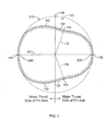
- the thrust force 254 may urge a major thrust surface 130 of the piston 100 against a major thrust side 230 of the cylinder wall 210.
- the thrust force component 254 may be in the thrust plane, which is a plane substantially normal to the pin axis 105 that may extend along a thrust axis 117 (also shown in FIG. 4 ) through the major thrust surface 130 of the piston 100.
- the thrust force 254 may generate a moment about the pin axis 105, causing the piston 100 to pivot about the pin axis 105 such that the piston axis 115 is angled from the cylinder bore axis at a rocking angle.
- the piston 100 may include a skirt portion 120 that bears against the cylinder wall 210-preferably with a hydrodynamic layer of lubricant therebetween. This skirt portion 120 may guide the piston 100 to restrict the rocking motion of the piston 100. In addition, the piston skirt 120 may flex when the thrust force 254 urges the piston 100 against the major thrust side 230 (described in more detail below).
- the piston 100 may react to a force from the rod 102 at the pin connection.
- the rod 102 may force the piston 100 to compress the combustion chamber in anticipation of a subsequent combustion event.
- a reaction component of the force from the rod 102 may be in the form of a thrust force that urges a minor thrust surface 140 of the piston 100 against that minor thrust side 240.
- the piston skirt 120 may guide the piston 100 to restrict the rocking motion of the piston 100.
- the piston 100 includes a piston head portion 110 and the piston skirt portion 120.
- the piston head 110 may include a piston top 112 that faces the combustion chamber described above in connection with FIG. 1A .
- the piston head 110 may include one or more ring grooves, such as one or more compressed-ring mounting grooves 113 (two shown) and one or more oil-ring mounting grooves 114 (one shown).
- the piston skirt 120 is adjacent the piston head 110 and begins at or about, and extends below, the bottom wall of the lowest ring groove (e.g., ring groove 114 in this embodiments) opposite the piston's top surface 112.
- the piston skirt 120 includes a generally hollow portion 121 proximal the bottom 122 of the piston 100.
- the piston skirt 120 may also include pin bores 124 aligned with the pin axis 105 to receive the pin 104.
- the pin 104 is joined with the pin bores 124 and is disposed in the hollow portion 121 of the skirt 120.
- the piston head 110 is generally more rigid than the piston skirt 120, and in some embodiments, may be a solid construction. As such, when the thrust force 254 urges the piston 100 against the major side 230 of the cylinder wall 210, the piston skirt 120 may flex substantially more than the piston head 110. However, the rigidity of the piston skirt 120 is not necessarily constant from the bottom 122 to the piston head 110. For example, in the embodiment shown in FIG. 1B , the circumferential wall 126 that surrounds the hollow portion 121 generally increases in thickness from the bottom 122 toward the piston head 110. In such circumstances, the piston skirt 120 may be more rigid near the piston head portion 110 of the piston 100 (where the wall thickness is greater).
- the axial profile (in the thrust plane) of the piston 100 is depicted schematically at operating temperature using axial profile line 150. Because of differences in temperature at different locations about the piston 100 that occur during operation, the amount of thermal expansion of the piston 100 along its axis may not be uniform. Accordingly, the axial profile of the piston 100 at ambient room temperature (most or all of the piston is at 25°C (77°F)) may be different than at operating temperature.
- the operating temperature is the temperature distribution about the piston 100 that is achieved and maintained when the engine 200 is operated at steady state for an extended time. The operating temperature may vary depending upon the configuration of the engine, but in general, the operating temperature is substantially greater than ambient room temperature. For example, at operating temperature, temperatures of the piston may be in the range of 65.6 °C to 538°C (150°F to 1000°F), and in some circumstances, in the range of (200°F to 700°F) 93.3° to 371°C
- the axial profile line 150 shows changes to the outer circumferential surface of the piston 100 in a direction along the piston axis 115.
- the axial profile line 150 illustrated in FIG. 1B represents the changes to the outer radius of the piston 100 relative to the axial height in a thrust plane cross-section.
- the thrust plane is substantially normal to the pin axis 105 and may extend along the thrust axis 117 (also shown in FIG. 4 ) through the major thrust surface 130 of the piston 100.
- the axial profile line 150 is shown in exaggerated form for illustrative purposes only. It should be understood that the change in the outer radius of the piston 100 may be small relative to the overall size of the piston 100, so the piston 100 may appear substantially cylindrical in shape when viewed from a distance.
- the axial profile line 150 along the major thrust surface 130 is similar in shape to the axial profile line 150 along the minor thrust surface 140.
- the axial profile line 150 may include a skirt profile line 152 coinciding with the skirt portion 120 and a head profile line 151 coinciding with the piston head portion 110.
- the head profile line 151 shows that, in this embodiment, the outer radius of the piston progressively decreases near the top surface 112 of the piston 100 (the head profile line 151 shown in FIG. 1B does not depict the exact contours of the piston at the grooves 113 and 114).
- the shape of the piston head 110 may provide some clearance space between top edge of the piston 100 and the cylinder wall 210. This clearance space may be required to reduce the likelihood of scuffing the cylinder wall 210 when the piston 100 is oriented at its maximum rocking angle.
- the piston 100 may be designed to have a reduced clearance space between top edge of the piston 100 and the cylinder wall 210.
- the piston skirt portion 120 may be configured to bear against the cylinder wall 210 and carry a substantial portion of the thrust load when the thrust force 254 urges the piston 100 against the cylinder wall 210.
- the tendency of the piston 100 to rock about the pin axis 105 may be reduced, which in turn permits a design having a reduced clearance space at the top edge of the piston 100.
- the head profile line 151 of the piston head 110 may have a constant outer radius which is smaller than the radius of the skirt portion 120.
- some clearance space between top edge of the piston 100 and the cylinder wall 210 would exist. Again, this clearance space can be reduced by causing the piston skirt 120 to bear against the cylinder wall 210 and carry a substantial portion of the thrust load when the thrust force 254 urges the piston 100 against the cylinder wall 210, as described in more detail below.
- the lower portion of the piston skirt 120 may include a maximum radius 155 in the thrust plane that is sized to be in interference with the cylinder wall 210 at operating temperatures. In such embodiments, no seizure of the piston 100 would occur due to flexure in the lower portion of the piston skirt 120.
- the lower portion of the piston skirt 120 flexes such that the lower portion of the skirt 120 is spring-loaded against the major thrust side 230 and the minor thrust side 240 of the cylinder wall 210. This interaction causes the lower portion of the skirt 120 to contribute in distribution of the thrust load, thereby distributing some of the load that might otherwise be applied at the upper skirt portion or at the head portion 110.
- By creating a more uniform load distribution along the piston skirt 120 the likelihood of generating local areas of relatively high stress concentrations is reduced, which in turn can reduce the likelihood of "polishing" or otherwise scuffing the cylinder wall 210.
- the piston 100 is provided with better guidance because the lower portion of the skirt 120 is spring-loaded against the major and minor thrust sides 230 and 240 of the cylinder wall 210 at operating temperatures.
- the tendency of the piston 100 to rock about the pin axis 105 may be reduced, which in turn permits a design having a minimal clearance space between the piston head 110 and the cylinder wall 210.
- this added friction may be negligible because a break in the hydrodynamic layer of lubricant between the cylinder wall 210 and the piston skirt 120 does not necessarily occur.
- these embodiments may provide a more uniform load distribution between the upper and lower portions of the skirt 120 (previously described), which may reduce the friction caused by "polishing" or otherwise scuffing the cylinder wall 210. Such a reduction in "polishing" friction may offset any friction potentially added by the lower portion of the piston skirt 120 being spring-loaded to bear against the major and minor thrust sides 230 and 240 of the cylinder wall 210 at operating temperatures.
- the polar profile line of the piston 100 at or about operating temperature is schematically depicted with a polar profile line 170.
- the polar profile line 170 shows the shape of the outer circumferential surface of the piston 100 in a cross-sectional radial plane.
- the polar profile line 170 is shown in a radial plane cross-section in the lower portion of the piston skirt 120 (see the cross-section line in FIG. 1 ).
- the general shape of the polar profile line 170 may be similar even if another radial plane cross-section is taken in another portion of the piston skirt 120.
- the size of the radii in the polar profile in another radial plane may be in proportion to the outer radius at the major and minor thrust surfaces 130 and 140 as shown in the axial profile line 150 and substantially follow the shape as shown in FIG. 2 .
- the polar profile line 170 is shown in exaggerated form for illustrative purposes only. It should be understood that changes in outer radius of the piston 100 in the radial plane may be small relative to the overall size of the piston 100, so the piston 100 may appear to have a circular cross-sectional shape when viewed from a distance.
- Various embodiments of the piston 100 may include piston skirts having cross-sectional shapes that do not perfectly coincide with the cross-sectional shape of the cylinder bore 205.
- the cross-sectional circumferential shape of the piston skirt 120 is somewhat like a modified ellipse and is not symmetrical about the pin axis 105.
- the cross-sectional circumferential shape may have a different appearance, such as an ellipse or a modified ellipse that is symmetrical about the pin axis 105.
- the piston 100 may have a polar profile design that is asymmetrical about a pin axis 105.
- the outer circumferential surface of the piston skirt 120 in the cross-sectional radial plane has a modified elliptical shape that is substantially symmetrical about the thrust axis 117.
- the maximum radii in the polar profile line 170 occur at the major thrust surface 130 and the minor thrust surface 140.
- the major thrust surface 130 and the minor thrust surface 140 are sufficiently sized to bear against the cylinder wall 210 along a major thrust side 230 and a minor thrust side 240, respectively.
- Such interaction between the piston skirt 120 and the cylinder wall 210 may cause the skirt 120 flex inward in a direction of the thrust axis 117 and correspondingly flex outward in a direction of pin axis 105.
- the thrust force 254 FIG. 1
- the major thrust surface 130 of the piston skirt may flex inward. This inward flexure causes the piston skirt 120 to flex outward in the direction of the pin axis 105.
- the radii along the non-thrust surfaces 132 and 142 of the piston skirt 120 may be smaller than the radii along the major and minor thrust surfaces 130 and 140 and may be smaller than the radius of the cylinder bore 205 at operating temperatures.
- the thrust loads on the major thrust surface 130 may be greater than on the minor thrust surface 140, so the piston skirt 120 may not uniformly flex outward.
- the minimum radius 175 may not extend in a direction parallel to the pin axis 105 but instead may extend toward the major thrust side of the pin axis 105 (e.g., the minimum radius point 176 in the polar profile line 170 is away from the pin axis 105 and toward the major thrust surface 130).
- polar profile line 170 is substantially symmetrical about the thrust axis 117, so the minimum radius point 176 exists on both sides of the thrust axis 117.
- the piston skirt 120 may flex outwardly more on the major thrust side than on the minor thrust side.
- many of the radii on the minor thrust side of the pin axis 105 may be relatively larger than the counterpart radii on the major thrust side of the pin axis 105.
- the relatively larger radii on the minor thrust side can provide a greater surface area to bear against the cylinder wall 210 and guide the piston 100.
- the minimum radius 175 on the major thrust side of the pin axis 105 may account for the outward flexure of the piston skirt 120 caused by the greater loading on the major thrust side of the pin axis 105.
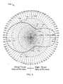
- FIG. 3 shows one example of the polar profile line 170 (for a piston 100 at or about operating temperature) represented in a plot. Because the scale for the piston skirt radius has been limited to a range of 75.7936 to 75.8952 mm (2.984 to 2.988 inches) in this example, the shape of the polar profile line 170 has been exaggerated. It should be understood that the dimensional scales shown in FIG. 3 are for illustrative purposes only, and that other embodiments may include a piston having various dimensions not illustrated in FIG. 3 . Furthermore, it should be understood that the polar profile's curvature, proportion, and shape shown in FIG.
- the polar profile line 170 shows that the outer circumferential surface of the piston skirt 120 in the cross-sectional radial plane has a modified elliptical shape which is asymmetrical about the pin axis 105 (and substantially symmetrical about the thrust axis 117).
- the minimum radius 175 has a length of about 75.8317 mm (2.9855 inches) and occurs at a point 176 on the major thrust side of the pin axis 105 at angle of about 25-degrees from the pin axis 105.
- the counterpart radius has a length of about 75.8571 mm (2.9865 inches) and occurs at a point 178 on the minor thrust side of the pin axis 105 at an angle of about 25-degrees from the pin axis 105.
- the maximum radius in this polar profile has a length of about 75.8901 mm (2.9878 inches) and occurs at the major and minor thrust surfaces 130 and 140.
- the radii along the non-thrust surfaces 132 and 142 are less than this maximum radius to provide clearance for the outward flexure of the piston skirt 120 in the direction of the pin axis 105.
- a piston may include the axial profile shown in FIG. 1 , and may also include a polar profile having a modified elliptical shape that is asymmetrical about the pin axis 105.
- a piston may include the axial profile shown in FIG. 1 , and may also include a polar profile having an elliptical shape that is symmetrical about the pin axis 105.
- the minimum radius may occur along the pin axis 105 and the maximum radius may occur along the thrust axis 117 at the major and minor thrust sides.
- a piston 300 may be configured so that the centroid of the thrust reaction forces imposed on the major thrust side of the piston 300 is located proximal to the center line 317 of the wrist pin. Such a configuration is capable of reducing the thrust force moment that would ordinarily cause a rocking motion of the piston 300. It should be understood that, in these embodiments, the thrust load is not necessarily distributed in a perfectly uniform manner along the entire major thrust side 330 of the piston skirt 320.
- the piston 300 can be configured such that the primary centroid of the reaction forces (represented as force centroid R1) is located at or slightly below the centerline height of the wrist pin.
- force centroid R1 the primary centroid of the reaction forces
- Such a configuration may effectively focus the thrust load to the more flexible portion of the piston skirt (the lower skirt portion in this embodiment) and away from the more rigid portions of the piston (the upper skirt portion and the piston head in this embodiment). This may reduce the likelihood of the more rigid portions of the piston causing scuffs along the cylinder wall, thereby permitting a substantially smaller clearance gap between the top land 316 that the cylinder wall.
- the thrust load may be concentrated below the ring grooves 313 and 314 where, in some embodiments, there is a more generous supply of engine oil or other lubricant to cushion the thrust load.
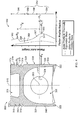
- FIG. 4 shows a cross-sectional view of the piston 300 in the thrust plane.
- the piston 300 may have some similar features to the previously described embodiments, but the piston 300 has a different axial profile 350.
- the piston may include a head portion 310, a skirt portion 320, a pin axis 305 and a piston axis 315.
- the head portion 310 may have a combustion bowl 311, a top surface 312, and ring grooves 313 and 314 that operate similar to the previously described embodiments.
- the skirt portion 320 may have a circumferential wall 326 that at least partially surrounds a hollow portion 321 proximal to the bottom 322 of the piston 300.
- the skirt portion 320 may include a major thrust side 330 and a minor thrust side 340 that may slidably engage the cylinder wall of an engine, similar to the previously described embodiments.
- the axial profile line 350 of the piston 300 may be represented on a plot showing the radius in the thrust plane relative to the axial height from the piston bottom 322.
- the plot in FIG. 6 illustrates the axial profile of the piston 300 at or about operating temperature (refer to the solid line) and at or about ambient room temperature (refer to the dashed line).
- the axial profile 350 of the piston 300 may be different depending on whether the piston 300 is at or about operating temperature or at or about ambient room temperature.
- the intermediate skirt profile 356 may be generally convex or linear when the piston is in a cooled state, but due to thermal expansion of the circumferential wall, the intermediate skirt profile 356 may adjust to include the concave curvature.
- the intermediate skirt profile 356 may include a concave curvature both when the piston 300 is in a thermally expanded state and when the piston 300 is in a cooled state.
- the piston skirt profile may include a lower skirt profile line 354, the intermediate skirt profile line 356, and an upper skirt profile line 358.
- at least a portion of the lower skirt profile line 354 may have a convex curvature including a maximum radius point 355.
- the lower skirt profile line 354 may include other curvatures or slopes.
- the lowest portion of the lower skirt profile line 354 may include a substantially linear profile that represents a linear reduction in the piston radius from the maximum radius point 355 to the piston bottom 322.
- the lowest portion of the lower skirt profile line 154 may include no reduction in the piston radius from a location at or about the maximum radius point 355 to a location at or about the piston bottom 322.
- the intermediate skirt profile line 354 may include a first inflection point 357, at which the lower skirt profile line 354 joins the intermediate skirt profile line 356. At least a portion of the intermediate skirt profile line 356 includes a concave curvature when the piston 300 is at or about operating temperature. Such a concave curvature may, for example, represent a substantial change of the piston skirt's radii in the thrust plane due to a substantial change in the rigidity of the piston skirt 320. It should be understood that other portions of the intermediate skirt profile line 356 may include other curvatures or slopes.
- the intermediate skirt profile line 356 may also include a second inflection point 359, at which the upper skirt profile line 358 joins the intermediate skirt profile line 356. At least a portion of the upper skirt profile line 358 may include a convex curvature or a linear slope that meets with the piston head profile line 360.
- At least some of the radii of the piston head profile line 360 in the thrust plane are larger than the radii of the upper skirt profile line 358 in the thrust plane.
- the radii along a portion of the top land 316 and the second land 318 may be greater than some of the radii of the upper skirt 358 when the piston 300 is at or about operating temperature, as shown in the offset portion 362 of the piston head profile line 360.
- the radii along the third land 319 may be substantially less than that of the top land 316 and the second land 318.
- Such a configuration may cause a radial offset 364 between the upper skirt and the piston head, which may be used to focus the centroid of the thrust reaction forces on the piston skirt 320 (represented as force centroid R1) to an axial position at or slightly below the centerline 317 of the wrist pin (described in more detail below).
- FIG. 5 shows one example of the axial profile line 350 represented in a plot where the piston is at or about operating temperature. Because the scale for the piston skirt radius has been limited to a range of 75.946 to 76.0984 mm (2.990 to 2.996 inches) in this example, the shape of the axial profile line 350 has been exaggerated. It should be understood that the dimensional scales shown in FIG. 7 are for illustrative purposes only, and that other embodiments may include a piston having various dimensions not illustrated in FIG. 7. Furthermore, it should be understood that the axial profile's curvature, proportion, and shape shown in FIG. 7 are for illustrative purposes only, and that other embodiments may include an axial profile having various curvatures, proportions, and shapes not illustrated in FIG 7.
- at least a portion of the intermediate skirt profile line 356 may include a concave curvature between inflection points 357 and 359.
- at least some of the radii in the piston head profile 360 are greater than some of the radii in the upper skirt profile 358, which creates a radial offset 364 when the piston 300 is at or about operating temperature.
- the lower portion of the piston skirt 320 may include a maximum radius (e.g., point 355) in the thrust plane that is sized to be in interference with the cylinder wall at operating temperatures. As previously described, no seizure of the piston 300 would occur due to flexure in the lower portion of the piston skirt 320.
- the lower portion of the piston skirt 320 is capable of flexing so that the lower portion of the skirt 320 is spring-loaded against the major thrust side and the minor thrust side of the cylinder wall. This interaction causes the lower portion of the skirt 320 to bear a substantial portion of the thrust reaction forces.
- the axial profile line 350 of the piston 300 in a thermally expanded state may be configured so that the radial offset 364 reduces the thrust reaction forces upon the upper skirt portion 356 (e.g., some portion of the upper skirt may not even contact the cylinder wall) and focuses the thrust reaction forces so that a centroid (represented as force centroid R1) is located at or slightly below the centerline 317 of the wrist pin (e.g., located at an axial height at or below the pivot axis 305).
- a centroid represented as force centroid R1
- Such a configuration is capable of reducing the thrust force moment that would ordinarily cause a rocking motion of the piston 300.
- such a configuration may reduce the likelihood of the more rigid portions of the piston 300 causing scuffs along the cylinder wall, thereby permitting a substantially smaller clearance gap between the top land 316 that the cylinder wall.
- the thrust reaction forces at the piston head 310 (represented as force centroid R2) are significantly smaller than the thrust reaction forces on the piston skirt (represented as force centroid R1).
- the wear caused by the piston head 310 may be small or insufficient to cause substantial scuffing.
- the radial offset 364 may substantially reduce or eliminate the contact between the cylinder wall and the upper skirt portion 358.
- the thrust load may be substantially distributed along two parts of the major thrust side 330-along the piston skirt 320 and along the piston head 310. These two parts may bear a different set of thrust reaction forces, which are represented as force centroid R1 and force centroid R2. Due to the axial profile shape of the skirt 320 and due to the radial offset 364 of the upper skirt portion, the force centroid R1 may occur at or slightly below the centerline 317 of the wrist pin (proximal to the maximum radius point 355).
- the force centroid R2 may occur along the major thrust side of the piston head (e.g., proximal to the second land 318 or the top land 316, and in this embodiment, above the third land 319).
- the thrust reaction forces can be expressed as a function of the thrust force which is transmitted through the pin centerline 317 (represented as force T in FIG. 4 ).
- R ⁇ 1 X ⁇ 2 X ⁇ 1 + X ⁇ 2 ⁇ T
- R ⁇ 2 X ⁇ 1 X ⁇ 1 + X ⁇ 2 ⁇ T
- X1 is the axial position of the centroid of the thrust reaction forces on the piston skirt 320 (represented as force centroid R1) relative to the height of the wrist pin centerline 317
- X2 is the axial position of the centroid of the thrust reaction forces on the piston head 310 (represented as force centroid R2) relative to the height of the wrist pin centerline 317 (refer, for example, to FIG. 4 ).
- the centroid (R1) of the thrust reaction forces on the piston skirt 320 may occur at or slightly below the height of the wrist pin centerline 317 so that X1 is relatively small (e.g., X1 ⁇ X2).
- X1 is relatively small
- the centroid (R2) of the thrust reaction forces on the piston head 310 becomes relatively small (e.g., R2 ⁇ R1).
- the thrust force (T) is substantially countered by the reaction forces on the piston skirt 320 (e.g., when R2 ⁇ R1, then R 1 ⁇ T). Accordingly, the thrust reaction forces on the piston head 310 (represented as centroid R2) may be substantially reduced, and the wear associated with the thrust reaction forces on the piston head 310 will likewise be reduced. As such, the wear caused by the piston head 310 may be small or insufficient to cause substantial scuffing, and the piston 300 may be configured to have a substantially smaller clearance gap between the top land 316 that the cylinder wall. A tight clearance gap may reduce the volume between the cylinder wall and piston head 316 above the sealing ring of the top land 316 (i.e.
- crevice volume Combustion mixture received in the crevice volume is typically not fully combusted and is thus exhausted as unburned hydrocarbons.
- the reduced crevice volume reduces the amount of unburned combustion mixture exhausted as undesirable emissions, because the volume of unburned combustion mixture is smaller.
- the tighter clearance gap between the top land 316 and the cylinder wall and the lower magnitude of the thrust reaction forces on the piston head 310 may substantially reduce wear on the top land 316, the piston ring(s), and the cylinder wall.
- the axial profile of the piston skirt 320 may be configured so that the reaction force centroid (R1) is aligned at or slightly below the height of the wrist pin centerline 317.
- the radial offset 364 may be increased to further reduce the amount of upper skirt portion 358 that bears upon the cylinder wall, which may cause the reaction force centroid (R1) to be located at a lower axial position on the skirt 320.
- the lower skirt portion 354 may include the maximum radius 355 proximal to the height of the wrist pin center line 317 so that as the thrust load increases and deflects the piston skirt 320, the loaded area of the skirt 320 may increase but the centroid (R1) of the thrust reaction forces on the piston skirt 320 may remain at or slightly below the pin centerline 317. In such circumstances, the magnitude of centroid (R1) for the thrust reaction forces on the piston skirt 320 would not exceed the magnitude of the thrust force (T). (If the reaction force centroid (R1) migrated towards the upper portion of the piston skirt 320, the axial position (X1) would have a negative value, thus causing the magnitude of reaction force centroid (R1)to be greater than the magnitude of the thrust force (T).)
- minor thrust side axial profile can, in some instances, be different than the major thrust side axial profile.
- radius one side may be different from the radius of the other. Accordingly, other embodiments are within the scope of the following claims.
Landscapes
- Engineering & Computer Science (AREA)
- General Engineering & Computer Science (AREA)
- Chemical & Material Sciences (AREA)
- Combustion & Propulsion (AREA)
- Mechanical Engineering (AREA)
- Pistons, Piston Rings, And Cylinders (AREA)
Abstract
Description
- This document relates to pistons for use in engines or the like.
- Various types of engines may use pistons in a cylinder bore. Each piston may reciprocate within its associated bore as a portion of the piston's outer circumferential surface is guided by the cylinder wall. The piston may include a skirt that is shaped to bear against the cylinder wall (with a hydrodynamic layer therebetween to provide lubrication) as the piston is reciprocated in the cylinder bore. In general, the lower portion of the piston within the piston skirt is substantially hollow while the upper portion of the piston near the piston face is solid. Accordingly, the piston may have non-uniform thermal expansion and non-uniform rigidity.
- Stress concentrations caused by the piston's thermal expansion, flexing, and rocking in the bore may cause the piston to "polish" or otherwise scuff the surface of the cylinder wall after repeated reciprocating movements. Also, thermal expansion of the piston material may increase the contact force between the piston and bore, causing high friction that may result in loss of efficiency and possible seizure of the piston in the cylinder bore. If the outer radius of the piston is too small, the outer circumferential surface may not sufficiently bear against the cylinder wall-causing the piston to excessively rock on the piston pin axis or vibrate within the cylinder bore.
-
JP 09170490A -
DE 37 40 820 C1 also discloses a piston for an internal combustion engine having a top portion and a skirt portion. The skirt portion of the piston has a convex shape. - The invention relates to an apparatus as claimed in
claim 1. - In some embodiments, an internal combustion engine may include at least one wall defining a bore, and a piston disposed in the bore and coupled to a piston rod to pivot about a pivot axis. The piston may include a substantially circumferential outer surface having a head portion and a skirt portion below the head portion. At least a portion of the outer surface may bear against the wall in a thrust plane when the piston is substantially at operating temperature and subject to a thrust force. The portion of the thrust force borne by the skirt portion in the thrust plane may be definable by a skirt force centroid, and the skirt force centroid may be positioned at an axial height at or below the pivot axis.
- A number of embodiments of a piston include a piston for use in an engine having a bore wall so that, when the piston is substantially at operating temperature and subject to a thrust force, the piston pivots about a pivot axis to bear against the bore wall in a thrust plane. The piston may include a substantially circumferential outer surface having a head portion and a skirt portion below the head portion. The head portion may have at least some radii in the thrust plane that are larger than at least some of the radii of the skirt portion when the piston is substantially at operating temperature so that the outer surface has a radial offset in the thrust plane above the pivot axis. The outer surface of the piston may bear at least a portion of the thrust force in the thrust plane. The portion of the thrust force borne by the skirt portion in the thrust plane may be definable by a skirt force centroid, and the skirt force centroid may be positioned at an axial height at or below the pivot axis. The portion of the thrust force borne by the head portion may be definable by a head force centroid, the head force centroid may be substantially smaller in magnitude than the skirt force centroid.
- These and other embodiments may be configured to provide one or more of the following advantages. First, the piston shape may provide better guidance within the cylinder bore. Second, the centroid of the thrust reaction forces on the piston skirt may occur at or slightly below the axial height of the pivot axis while the thrust reaction forces on the piston head are relatively small. As such, the thrust force moment that would ordinarily cause a rocking motion of the piston may be reduced. Third, the wear associated with the thrust reaction forces on the piston head may be may be small or insufficient to cause substantial scuffing. As such, the piston may be configured to have a substantially smaller clearance gap between the top land that the cylinder wall, which may reduce undesirable emissions. Moreover, in some circumstances the tighter clearance gap between the top land and the cylinder wall and the lower magnitude of the thrust reaction forces on the piston head may substantially reduce wear on the top land, the piston ring(s), and the cylinder wall.
- The details of one or more embodiments of the invention are set forth in the accompanying drawings and the description below. Other features, objects, and advantages of the invention will be apparent from the description and drawings, and from the claims.
-
-
FIG. 1A is a side view of a piston and a portion of an engine in accordance with some embodiments of the invention. -
FIG. 1B is a side view of the piston ofFIG. 1A . -
FIG. 2 is a schematic view of a cross-section of a piston in accordance with some further embodiments of the invention. -
FIG. 3 is a diagram showing an example of a polar profile of a piston in accordance with an embodiment of the invention. -
FIG. 4 is a cross-sectional view of a piston in accordance with some embodiments of the invention. -
FIG. 5 is a diagram showing an example of an axial profile of a piston head and piston skirt in accordance with an embodiment of the invention. - Like reference symbols in the various drawings indicate like elements.
- Referring to
FIGS. 1A-B , apiston 100 is capable of reciprocating within acylinder bore 205 of an engine 200 (a portion of theengine 200 has been removed fromFIG. 1A to better view the piston 100). A hydrodynamic layer of oil or other lubricant may coat portions of thecylinder wall 210 to reduce friction between thepiston 100 and thecylinder wall 210. Thepiston 100 may be pivotably engaged with apiston rod 102 using apin 104. In such circumstances, thepiston 100 may pivot about a pivot orpin axis 105 relative to therod 102. The pin connection permits thepiston 100 to transmit forces to, or receive forces from, therod 102 as thepiston 100 reciprocates within thebore 205. In certain embodiments, thepiston 100 is constructed in whole or in part from aluminum or alloys containing aluminum, carbon (e.g. carbon fiber and carbon/carbon), iron, steel, or other suitable materials and may include combinations of the above-mentioned or other materials. - Referring to
FIG. 1A , thecylinder bore 205 may define at least a portion of a combustion chamber where acombustion event 250 exerts a force on thepiston 100 and causes an expansion stroke. The combustion pressure may be transferred to thepiston 100 in a direction substantially parallel to the axis of the cylinder bore 205 because at least a portion of the piston's top surface 112 (FIG. 1B ) may be substantially perpendicular to the axis of thecylinder bore 205. A portion of the force from thecombustion event 250 may be transmitted as arod force component 252 to the rod 102 (in a longitudinal direction of the rod 102).
Also, because therod 102 may not be aligned with the direction of the combustion force, a portion of the force from thecombustion event 250 may be transmitted as athrust force component 254. - The
thrust force 254 may urge amajor thrust surface 130 of thepiston 100 against amajor thrust side 230 of thecylinder wall 210. Thethrust force component 254 may be in the thrust plane, which is a plane substantially normal to thepin axis 105 that may extend along a thrust axis 117 (also shown inFIG. 4 ) through themajor thrust surface 130 of thepiston 100. Thethrust force 254 may generate a moment about thepin axis 105, causing thepiston 100 to pivot about thepin axis 105 such that thepiston axis 115 is angled from the cylinder bore axis at a rocking angle. - To provide guidance during the reciprocation motion and to limit the rocking angle of the piston 100 (excessive rocking could cause stress concentrations that "polish" or otherwise scuff the cylinder wall 210), the
piston 100 may include askirt portion 120 that bears against the cylinder wall 210-preferably with a hydrodynamic layer of lubricant therebetween. Thisskirt portion 120 may guide thepiston 100 to restrict the rocking motion of thepiston 100. In addition, thepiston skirt 120 may flex when thethrust force 254 urges thepiston 100 against the major thrust side 230 (described in more detail below). - It should be understood that, during the compression stroke (not shown in
FIG. 1A ), thepiston 100 may react to a force from therod 102 at the pin connection. In some instances, therod 102 may force thepiston 100 to compress the combustion chamber in anticipation of a subsequent combustion event. A reaction component of the force from therod 102 may be in the form of a thrust force that urges aminor thrust surface 140 of thepiston 100 against thatminor thrust side 240. Again, in such circumstances, thepiston skirt 120 may guide thepiston 100 to restrict the rocking motion of thepiston 100. - Referring to
FIG. 1B , thepiston 100 includes apiston head portion 110 and thepiston skirt portion 120. Thepiston head 110 may include apiston top 112 that faces the combustion chamber described above in connection withFIG. 1A . Thepiston head 110 may include one or more ring grooves, such as one or more compressed-ring mounting grooves 113 (two shown) and one or more oil-ring mounting grooves 114 (one shown). In general, thepiston skirt 120 is adjacent thepiston head 110 and begins at or about, and extends below, the bottom wall of the lowest ring groove (e.g.,ring groove 114 in this embodiments) opposite the piston'stop surface 112. Thepiston skirt 120 includes a generallyhollow portion 121 proximal thebottom 122 of thepiston 100. Thepiston skirt 120 may also include pin bores 124 aligned with thepin axis 105 to receive thepin 104. Thepin 104 is joined with the pin bores 124 and is disposed in thehollow portion 121 of theskirt 120. - The
piston head 110 is generally more rigid than thepiston skirt 120, and in some embodiments, may be a solid construction. As such, when thethrust force 254 urges thepiston 100 against themajor side 230 of thecylinder wall 210, thepiston skirt 120 may flex substantially more than thepiston head 110. However, the rigidity of thepiston skirt 120 is not necessarily constant from the bottom 122 to thepiston head 110. For example, in the embodiment shown inFIG. 1B , thecircumferential wall 126 that surrounds thehollow portion 121 generally increases in thickness from the bottom 122 toward thepiston head 110. In such circumstances, thepiston skirt 120 may be more rigid near thepiston head portion 110 of the piston 100 (where the wall thickness is greater). - Still referring to
FIG. 1 B , the axial profile (in the thrust plane) of thepiston 100 is depicted schematically at operating temperature usingaxial profile line 150. Because of differences in temperature at different locations about thepiston 100 that occur during operation, the amount of thermal expansion of thepiston 100 along its axis may not be uniform. Accordingly, the axial profile of thepiston 100 at ambient room temperature (most or all of the piston is at 25°C (77°F)) may be different than at operating temperature. The operating temperature is the temperature distribution about thepiston 100 that is achieved and maintained when theengine 200 is operated at steady state for an extended time. The operating temperature may vary depending upon the configuration of the engine, but in general, the operating temperature is substantially greater than ambient room temperature. For example, at operating temperature, temperatures of the piston may be in the range of 65.6 °C to 538°C (150°F to 1000°F), and in some circumstances, in the range of (200°F to 700°F) 93.3° to 371°C - The
axial profile line 150 shows changes to the outer circumferential surface of thepiston 100 in a direction along thepiston axis 115. Theaxial profile line 150 illustrated inFIG. 1B represents the changes to the outer radius of thepiston 100 relative to the axial height in a thrust plane cross-section. As previously described, the thrust plane is substantially normal to thepin axis 105 and may extend along the thrust axis 117 (also shown inFIG. 4 ) through themajor thrust surface 130 of thepiston 100. Theaxial profile line 150 is shown in exaggerated form for illustrative purposes only. It should be understood that the change in the outer radius of thepiston 100 may be small relative to the overall size of thepiston 100, so thepiston 100 may appear substantially cylindrical in shape when viewed from a distance. In this embodiment, theaxial profile line 150 along themajor thrust surface 130 is similar in shape to theaxial profile line 150 along theminor thrust surface 140. - The
axial profile line 150 may include askirt profile line 152 coinciding with theskirt portion 120 and ahead profile line 151 coinciding with thepiston head portion 110. Thehead profile line 151 shows that, in this embodiment, the outer radius of the piston progressively decreases near thetop surface 112 of the piston 100 (thehead profile line 151 shown inFIG. 1B does not depict the exact contours of the piston at thegrooves 113 and 114). As such, the shape of thepiston head 110 may provide some clearance space between top edge of thepiston 100 and thecylinder wall 210. This clearance space may be required to reduce the likelihood of scuffing thecylinder wall 210 when thepiston 100 is oriented at its maximum rocking angle. The efficiency of transferring the combustion pressure to thepiston 100 may be increased, however, if the clearance space between top edge of thepiston 100 and thecylinder wall 210 is reduced. In this embodiment, thepiston 100 may be designed to have a reduced clearance space between top edge of thepiston 100 and thecylinder wall 210. As described in more detail below, thepiston skirt portion 120 may be configured to bear against thecylinder wall 210 and carry a substantial portion of the thrust load when thethrust force 254 urges thepiston 100 against thecylinder wall 210. When thepiston skirt portion 120 bears against thecylinder wall 210 and provides sufficient guidance to thepiston 100, the tendency of thepiston 100 to rock about thepin axis 105 may be reduced, which in turn permits a design having a reduced clearance space at the top edge of thepiston 100. - Alternatively, the
head profile line 151 of thepiston head 110 may have a constant outer radius which is smaller than the radius of theskirt portion 120. In such embodiments, some clearance space between top edge of thepiston 100 and thecylinder wall 210 would exist. Again, this clearance space can be reduced by causing thepiston skirt 120 to bear against thecylinder wall 210 and carry a substantial portion of the thrust load when thethrust force 254 urges thepiston 100 against thecylinder wall 210, as described in more detail below. - In some embodiments, including the previously described embodiments, the lower portion of the
piston skirt 120 may include amaximum radius 155 in the thrust plane that is sized to be in interference with thecylinder wall 210 at operating temperatures. In such embodiments, no seizure of thepiston 100 would occur due to flexure in the lower portion of thepiston skirt 120. The lower portion of thepiston skirt 120 flexes such that the lower portion of theskirt 120 is spring-loaded against themajor thrust side 230 and theminor thrust side 240 of thecylinder wall 210. This interaction causes the lower portion of theskirt 120 to contribute in distribution of the thrust load, thereby distributing some of the load that might otherwise be applied at the upper skirt portion or at thehead portion 110. By creating a more uniform load distribution along thepiston skirt 120, the likelihood of generating local areas of relatively high stress concentrations is reduced, which in turn can reduce the likelihood of "polishing" or otherwise scuffing thecylinder wall 210. - Also in some embodiments, the
piston 100 is provided with better guidance because the lower portion of theskirt 120 is spring-loaded against the major andminor thrust sides cylinder wall 210 at operating temperatures. As previously described, when thepiston skirt portion 120 bears against thecylinder wall 210 in such a manner and provides sufficient guidance to thepiston 100, the tendency of thepiston 100 to rock about thepin axis 105 may be reduced, which in turn permits a design having a minimal clearance space between thepiston head 110 and thecylinder wall 210. In such circumstances, it is possible that friction may be added to the system when the lower portion of theskirt 120 is spring-loaded to bear against the major andminor thrust sides cylinder wall 210 at operating temperatures. However, this added friction may be negligible because a break in the hydrodynamic layer of lubricant between thecylinder wall 210 and thepiston skirt 120 does not necessarily occur. Furthermore, these embodiments may provide a more uniform load distribution between the upper and lower portions of the skirt 120 (previously described), which may reduce the friction caused by "polishing" or otherwise scuffing thecylinder wall 210. Such a reduction in "polishing" friction may offset any friction potentially added by the lower portion of thepiston skirt 120 being spring-loaded to bear against the major andminor thrust sides cylinder wall 210 at operating temperatures. - Referring to
FIG. 2 , the polar profile line of thepiston 100 at or about operating temperature is schematically depicted with apolar profile line 170. Thepolar profile line 170 shows the shape of the outer circumferential surface of thepiston 100 in a cross-sectional radial plane. In this embodiment, thepolar profile line 170 is shown in a radial plane cross-section in the lower portion of the piston skirt 120 (see the cross-section line inFIG. 1 ). The general shape of thepolar profile line 170 may be similar even if another radial plane cross-section is taken in another portion of thepiston skirt 120. The size of the radii in the polar profile in another radial plane may be in proportion to the outer radius at the major and minor thrust surfaces 130 and 140 as shown in theaxial profile line 150 and substantially follow the shape as shown inFIG. 2 . - The
polar profile line 170 is shown in exaggerated form for illustrative purposes only. It should be understood that changes in outer radius of thepiston 100 in the radial plane may be small relative to the overall size of thepiston 100, so thepiston 100 may appear to have a circular cross-sectional shape when viewed from a distance. Various embodiments of thepiston 100 may include piston skirts having cross-sectional shapes that do not perfectly coincide with the cross-sectional shape of thecylinder bore 205. In the embodiment shown inFIG. 4 , the cross-sectional circumferential shape of thepiston skirt 120 is somewhat like a modified ellipse and is not symmetrical about thepin axis 105. In other embodiments, the cross-sectional circumferential shape may have a different appearance, such as an ellipse or a modified ellipse that is symmetrical about thepin axis 105. - Referring to
FIG. 2 , thepiston 100 may have a polar profile design that is asymmetrical about apin axis 105. In this embodiment, the outer circumferential surface of thepiston skirt 120 in the cross-sectional radial plane has a modified elliptical shape that is substantially symmetrical about thethrust axis 117. The maximum radii in thepolar profile line 170 occur at themajor thrust surface 130 and theminor thrust surface 140. In this radial plane, themajor thrust surface 130 and theminor thrust surface 140 are sufficiently sized to bear against thecylinder wall 210 along amajor thrust side 230 and aminor thrust side 240, respectively. Such interaction between thepiston skirt 120 and thecylinder wall 210 may cause theskirt 120 flex inward in a direction of thethrust axis 117 and correspondingly flex outward in a direction ofpin axis 105. For example, when the thrust force 254 (FIG. 1 ) urges themajor thrust surface 130 against themajor thrust side 230 of thecylinder wall 210, themajor thrust surface 130 of the piston skirt may flex inward. This inward flexure causes thepiston skirt 120 to flex outward in the direction of thepin axis 105. To allow clearance for this outward flexure in the direction of thepin axis 105, the radii along thenon-thrust surfaces piston skirt 120 may be smaller than the radii along the major and minor thrust surfaces 130 and 140 and may be smaller than the radius of the cylinder bore 205 at operating temperatures. - The thrust loads on the
major thrust surface 130 may be greater than on theminor thrust surface 140, so thepiston skirt 120 may not uniformly flex outward. In such embodiments, theminimum radius 175 may not extend in a direction parallel to thepin axis 105 but instead may extend toward the major thrust side of the pin axis 105 (e.g., theminimum radius point 176 in thepolar profile line 170 is away from thepin axis 105 and toward the major thrust surface 130). In this embodiment,polar profile line 170 is substantially symmetrical about thethrust axis 117, so theminimum radius point 176 exists on both sides of thethrust axis 117. Because the thrust loads on themajor thrust surface 130 may be greater than on theminor thrust surface 140, thepiston skirt 120 may flex outwardly more on the major thrust side than on the minor thrust side. To account for this non uniform flexure of thepiston skirt 120, many of the radii on the minor thrust side of thepin axis 105 may be relatively larger than the counterpart radii on the major thrust side of thepin axis 105. The relatively larger radii on the minor thrust side can provide a greater surface area to bear against thecylinder wall 210 and guide thepiston 100. Theminimum radius 175 on the major thrust side of thepin axis 105 may account for the outward flexure of thepiston skirt 120 caused by the greater loading on the major thrust side of thepin axis 105. -
FIG. 3 shows one example of the polar profile line 170 (for apiston 100 at or about operating temperature) represented in a plot. Because the scale for the piston skirt radius has been limited to a range of 75.7936 to 75.8952 mm (2.984 to 2.988 inches) in this example, the shape of thepolar profile line 170 has been exaggerated. It should be understood that the dimensional scales shown inFIG. 3 are for illustrative purposes only, and that other embodiments may include a piston having various dimensions not illustrated inFIG. 3 . Furthermore, it should be understood that the polar profile's curvature, proportion, and shape shown inFIG. 3 are for illustrative purposes only, and that other embodiments may include a polar profile having various curvatures, proportions, and shapes not illustrated inFIG. 3 . In this example, thepolar profile line 170 shows that the outer circumferential surface of thepiston skirt 120 in the cross-sectional radial plane has a modified elliptical shape which is asymmetrical about the pin axis 105 (and substantially symmetrical about the thrust axis 117). - Referring to
FIG. 3 , in this example, many of the radii on the minor thrust side of thepin axis 105 may be relatively larger than the counterpart radii on the major thrust side of thepin axis 105. For example, theminimum radius 175 has a length of about 75.8317 mm (2.9855 inches) and occurs at apoint 176 on the major thrust side of thepin axis 105 at angle of about 25-degrees from thepin axis 105. The counterpart radius has a length of about 75.8571 mm (2.9865 inches) and occurs at apoint 178 on the minor thrust side of thepin axis 105 at an angle of about 25-degrees from thepin axis 105. The maximum radius in this polar profile has a length of about 75.8901 mm (2.9878 inches) and occurs at the major and minor thrust surfaces 130 and 140. The radii along thenon-thrust surfaces piston skirt 120 in the direction of thepin axis 105. - Other embodiments of the piston may include a polar profile that is not illustrated in
FIG. 2 orFIG. 3 . For example, a piston may include the axial profile shown inFIG. 1 , and may also include a polar profile having a modified elliptical shape that is asymmetrical about thepin axis 105. In another example, a piston may include the axial profile shown inFIG. 1 , and may also include a polar profile having an elliptical shape that is symmetrical about thepin axis 105. In embodiments having a symmetrical polar profile, the minimum radius may occur along thepin axis 105 and the maximum radius may occur along thethrust axis 117 at the major and minor thrust sides. - Referring now to
FIG. 4 , some embodiments of apiston 300 may be configured so that the centroid of the thrust reaction forces imposed on the major thrust side of thepiston 300 is located proximal to thecenter line 317 of the wrist pin. Such a configuration is capable of reducing the thrust force moment that would ordinarily cause a rocking motion of thepiston 300. It should be understood that, in these embodiments, the thrust load is not necessarily distributed in a perfectly uniform manner along the entiremajor thrust side 330 of thepiston skirt 320. Even if some portions of themajor thrust side 330 of thepiston skirt 320 bear a greater share of the thrust load, thepiston 300 can be configured such that the primary centroid of the reaction forces (represented as force centroid R1) is located at or slightly below the centerline height of the wrist pin. Such a configuration may effectively focus the thrust load to the more flexible portion of the piston skirt (the lower skirt portion in this embodiment) and away from the more rigid portions of the piston (the upper skirt portion and the piston head in this embodiment). This may reduce the likelihood of the more rigid portions of the piston causing scuffs along the cylinder wall, thereby permitting a substantially smaller clearance gap between thetop land 316 that the cylinder wall. Furthermore, the thrust load may be concentrated below thering grooves -
FIG. 4 shows a cross-sectional view of thepiston 300 in the thrust plane. Thepiston 300 may have some similar features to the previously described embodiments, but thepiston 300 has a differentaxial profile 350. The piston may include ahead portion 310, askirt portion 320, apin axis 305 and apiston axis 315. Thehead portion 310 may have acombustion bowl 311, atop surface 312, andring grooves skirt portion 320 may have acircumferential wall 326 that at least partially surrounds ahollow portion 321 proximal to thebottom 322 of thepiston 300. Theskirt portion 320 may include amajor thrust side 330 and aminor thrust side 340 that may slidably engage the cylinder wall of an engine, similar to the previously described embodiments. - The
axial profile line 350 of thepiston 300 may be represented on a plot showing the radius in the thrust plane relative to the axial height from thepiston bottom 322. The plot in FIG. 6 illustrates the axial profile of thepiston 300 at or about operating temperature (refer to the solid line) and at or about ambient room temperature (refer to the dashed line). As previously described, theaxial profile 350 of thepiston 300 may be different depending on whether thepiston 300 is at or about operating temperature or at or about ambient room temperature. In this embodiment, theintermediate skirt profile 356 may be generally convex or linear when the piston is in a cooled state, but due to thermal expansion of the circumferential wall, theintermediate skirt profile 356 may adjust to include the concave curvature. In other embodiments, theintermediate skirt profile 356 may include a concave curvature both when thepiston 300 is in a thermally expanded state and when thepiston 300 is in a cooled state. - Still referring to
FIG. 4 , the piston skirt profile may include a lowerskirt profile line 354, the intermediateskirt profile line 356, and an upperskirt profile line 358. In this embodiment, at least a portion of the lowerskirt profile line 354 may have a convex curvature including amaximum radius point 355. It should be understood that in other embodiments the lowerskirt profile line 354 may include other curvatures or slopes. For example, the lowest portion of the lowerskirt profile line 354 may include a substantially linear profile that represents a linear reduction in the piston radius from themaximum radius point 355 to thepiston bottom 322. In other instances, the lowest portion of the lowerskirt profile line 154 may include no reduction in the piston radius from a location at or about themaximum radius point 355 to a location at or about thepiston bottom 322. The intermediateskirt profile line 354 may include afirst inflection point 357, at which the lowerskirt profile line 354 joins the intermediateskirt profile line 356. At least a portion of the intermediateskirt profile line 356 includes a concave curvature when thepiston 300 is at or about operating temperature. Such a concave curvature may, for example, represent a substantial change of the piston skirt's radii in the thrust plane due to a substantial change in the rigidity of thepiston skirt 320. It should be understood that other portions of the intermediateskirt profile line 356 may include other curvatures or slopes. The intermediateskirt profile line 356 may also include asecond inflection point 359, at which the upperskirt profile line 358 joins the intermediateskirt profile line 356. At least a portion of the upperskirt profile line 358 may include a convex curvature or a linear slope that meets with the pistonhead profile line 360. - In this embodiment, at least some of the radii of the piston
head profile line 360 in the thrust plane are larger than the radii of the upperskirt profile line 358 in the thrust plane. For example, the radii along a portion of thetop land 316 and thesecond land 318 may be greater than some of the radii of theupper skirt 358 when thepiston 300 is at or about operating temperature, as shown in the offsetportion 362 of the pistonhead profile line 360. Also, in some embodiments the radii along thethird land 319 may be substantially less than that of thetop land 316 and thesecond land 318. Such a configuration may cause a radial offset 364 between the upper skirt and the piston head, which may be used to focus the centroid of the thrust reaction forces on the piston skirt 320 (represented as force centroid R1) to an axial position at or slightly below thecenterline 317 of the wrist pin (described in more detail below). -
FIG. 5 shows one example of theaxial profile line 350 represented in a plot where the piston is at or about operating temperature. Because the scale for the piston skirt radius has been limited to a range of 75.946 to 76.0984 mm (2.990 to 2.996 inches) in this example, the shape of theaxial profile line 350 has been exaggerated. It should be understood that the dimensional scales shown in FIG. 7 are for illustrative purposes only, and that other embodiments may include a piston having various dimensions not illustrated in FIG. 7. Furthermore, it should be understood that the axial profile's curvature, proportion, and shape shown in FIG. 7 are for illustrative purposes only, and that other embodiments may include an axial profile having various curvatures, proportions, and shapes not illustrated in FIG 7. In this example, the lowest portion of the lower skirt profile line 354 (e.g., near the bottom 322 at axial height = 0.000) includes a convex curvature inward or a linear slope inward to avoid gouging the cylinder wall during the reciprocating motion of thepiston 300 and to avoid, in some circumstances, an interference fit when thepiston 300 is at ambient room temperature. As previously described, at least a portion of the intermediateskirt profile line 356 may include a concave curvature betweeninflection points piston head profile 360 are greater than some of the radii in theupper skirt profile 358, which creates a radial offset 364 when thepiston 300 is at or about operating temperature. - In the embodiments and examples described in connection with
FIGS. 4-5 , the lower portion of thepiston skirt 320 may include a maximum radius (e.g., point 355) in the thrust plane that is sized to be in interference with the cylinder wall at operating temperatures. As previously described, no seizure of thepiston 300 would occur due to flexure in the lower portion of thepiston skirt 320. The lower portion of thepiston skirt 320 is capable of flexing so that the lower portion of theskirt 320 is spring-loaded against the major thrust side and the minor thrust side of the cylinder wall. This interaction causes the lower portion of theskirt 320 to bear a substantial portion of the thrust reaction forces. Moreover, theaxial profile line 350 of thepiston 300 in a thermally expanded state may be configured so that the radial offset 364 reduces the thrust reaction forces upon the upper skirt portion 356 (e.g., some portion of the upper skirt may not even contact the cylinder wall) and focuses the thrust reaction forces so that a centroid (represented as force centroid R1) is located at or slightly below thecenterline 317 of the wrist pin (e.g., located at an axial height at or below the pivot axis 305). Such a configuration is capable of reducing the thrust force moment that would ordinarily cause a rocking motion of thepiston 300. Also, such a configuration may reduce the likelihood of the more rigid portions of thepiston 300 causing scuffs along the cylinder wall, thereby permitting a substantially smaller clearance gap between thetop land 316 that the cylinder wall. In such circumstances, even if thetop land 316 or other portion of thepiston head 310 bears against the major thrust side of the cylinder wall, the thrust reaction forces at the piston head 310 (represented as force centroid R2) are significantly smaller than the thrust reaction forces on the piston skirt (represented as force centroid R1). As such, the wear caused by thepiston head 310 may be small or insufficient to cause substantial scuffing. - Referring to
FIGS. 4 and5 , the radial offset 364 may substantially reduce or eliminate the contact between the cylinder wall and theupper skirt portion 358. As such, the thrust load may be substantially distributed along two parts of the major thrust side 330-along thepiston skirt 320 and along thepiston head 310. These two parts may bear a different set of thrust reaction forces, which are represented as force centroid R1 and force centroid R2. Due to the axial profile shape of theskirt 320 and due to the radial offset 364 of the upper skirt portion, the force centroid R1 may occur at or slightly below thecenterline 317 of the wrist pin (proximal to the maximum radius point 355). Also, because thepiston head 310 may bear against the cylinder wall in response to a thrust force, the force centroid R2 may occur along the major thrust side of the piston head (e.g., proximal to thesecond land 318 or thetop land 316, and in this embodiment, above the third land 319). - Presuming that the
piston 300 has no transverse acceleration force (this presumption is valid once the piston is pushed up against the cylinder liner after it moves due to secondary motion), the thrust reaction forces can be expressed as a function of the thrust force which is transmitted through the pin centerline 317 (represented as force T inFIG. 4 ). These expressions are as follows:
where X1 is the axial position of the centroid of the thrust reaction forces on the piston skirt 320 (represented as force centroid R1) relative to the height of thewrist pin centerline 317, and where X2 is the axial position of the centroid of the thrust reaction forces on the piston head 310 (represented as force centroid R2) relative to the height of the wrist pin centerline 317 (refer, for example, toFIG. 4 ). - Because the radial offset 364 may substantially reduce or eliminate the contact between the cylinder wall and the
upper skirt portion 358, and due to themaximum radius point 355 being located at or near the height of thewrist pin centerline 317, the centroid (R1) of the thrust reaction forces on thepiston skirt 320 may occur at or slightly below the height of thewrist pin centerline 317 so that X1 is relatively small (e.g., X1 << X2). When X1 is much smaller than X2, the centroid (R2) of the thrust reaction forces on thepiston head 310 becomes relatively small (e.g., R2 << R1). In such circumstances where R2 is much smaller than R1, the thrust force (T) is substantially countered by the reaction forces on the piston skirt 320 (e.g., when R2 << R1, then R1 ≅ T). Accordingly, the thrust reaction forces on the piston head 310 (represented as centroid R2) may be substantially reduced, and the wear associated with the thrust reaction forces on thepiston head 310 will likewise be reduced. As such, the wear caused by thepiston head 310 may be small or insufficient to cause substantial scuffing, and thepiston 300 may be configured to have a substantially smaller clearance gap between thetop land 316 that the cylinder wall. A tight clearance gap may reduce the volume between the cylinder wall andpiston head 316 above the sealing ring of the top land 316 (i.e. the crevice volume). Combustion mixture received in the crevice volume is typically not fully combusted and is thus exhausted as unburned hydrocarbons. The reduced crevice volume reduces the amount of unburned combustion mixture exhausted as undesirable emissions, because the volume of unburned combustion mixture is smaller. Furthermore, the tighter clearance gap between thetop land 316 and the cylinder wall and the lower magnitude of the thrust reaction forces on thepiston head 310 may substantially reduce wear on thetop land 316, the piston ring(s), and the cylinder wall. - Still referring to embodiments and examples described in connection with
FIGS. 4-5 , the axial profile of thepiston skirt 320 may be configured so that the reaction force centroid (R1) is aligned at or slightly below the height of thewrist pin centerline 317. For example, the radial offset 364 may be increased to further reduce the amount ofupper skirt portion 358 that bears upon the cylinder wall, which may cause the reaction force centroid (R1) to be located at a lower axial position on theskirt 320. Also, thelower skirt portion 354 may include themaximum radius 355 proximal to the height of the wristpin center line 317 so that as the thrust load increases and deflects thepiston skirt 320, the loaded area of theskirt 320 may increase but the centroid (R1) of the thrust reaction forces on thepiston skirt 320 may remain at or slightly below thepin centerline 317. In such circumstances, the magnitude of centroid (R1) for the thrust reaction forces on thepiston skirt 320 would not exceed the magnitude of the thrust force (T). (If the reaction force centroid (R1) migrated towards the upper portion of thepiston skirt 320, the axial position (X1) would have a negative value, thus causing the magnitude of reaction force centroid (R1)to be greater than the magnitude of the thrust force (T).) - A number of embodiments of the invention have been described. Nevertheless, it will be understood that various modifications may be made without departing from the scope of the invention. For example, the minor thrust side axial profile can, in some instances, be different than the major thrust side axial profile. Also, in instances where the axial profiles on the major and minor thrust sides are substantially the same, the radius one side may be different from the radius of the other. Accordingly, other embodiments are within the scope of the following claims.
Claims (13)
- An internal combustion engine, comprising:at least one wall (210) defining a bore (205); anda piston (300) disposed in the bore (205) and coupled to a piston rod (102) to pivot about a pivot axis (305), the piston comprising a substantially circumferential outer surface having a head-portion (310) and a skirt profile line (320) below the head portion (310), at least a portion of the outer surface bearing against the wall (210) in a thrust plane when the piston (300) is substantially at operating temperature and subject to a thrust force (T), the portion of the thrust force (T) borne by the skirt profile line (320) in the thrust plane is definable by a skirt force centroid (R1), the skirt force centroid (R1) being positioned at an axial height at or below the pivot axis (305),wherein the head portion (310) of the outer surface has radii that are larger than at least some of the radii of the skirt profile line (320) of the outer surface when the piston is substantially at operating temperature.
- The engine of claim 1, wherein the portion of the thrust force (T) borne by the head portion (310) is definable by a head force centroid (R2), the head force centroid (R2) being substantially smaller in magnitude than the skirt force centroid (R1).
- The engine of claim 2, wherein the head force centroid (R2) is positioned at an axial height above the pivot axis (305), the head force centroid being positioned a substantially greater distance from the pivot axis (305) than the skirt force centroid (R1).
- The engine of claim 1, wherein the outer surface has a profile (350) in the thrust plane that includes a lower skirt profile line (354), an intermediate skirt profile line (356), and an upper skirt profile line (358), the intermediate skirt profile line (356) including a concave curvature in the thrust plane when the piston (300) is substantially at operating temperature.
- The engine of claim 4, wherein the profile (350) in the thrust plane of the outer circumferential surface transitions from a substantially convex curvature of the lower skirt profile line (354) in the thrust plane to the substantially concave curvature of the intermediate skirt profile line (356).
- The engine of claim 1, wherein the outer surface has a profile (350) in the thrust plane that includes a lower skirt profile line (354), an intermediate skirt profile line (356), and an upper skirt profile line (358), the outer surface having a radial offset (364) in the thrust plane above the pivot axis (305) when the piston (300) is substantially at operating temperature.
- The engine of claim 6, wherein the upper skirt profile line (358) includes radii in the thrust plane that are smaller than at least some radii of the head portion (310) when the piston (300) is substantially at operating temperature.
- The engine of claim 1, wherein the outer surface has a profile (350) in the thrust plane that includes a lower skirt profile line (354), an intermediate skirt profile line (356), and an upper skirt profile line (358), lower skirt profile line (354) having a maximum radius that is in an interference fit with the wall (210) when the piston (300) is substantially at operating temperature.
- The engine of claim 8, wherein a lower skirt portion defined by the lower skirt profile line (354) flexes when in the interference fit to avoid seizure of the piston (300) in the bore (205).
- The engine of claim 8, wherein a lower skirt portion defined by the lower skirt profile line (354) is spring-loaded against major and minor thrust sides (230 and 240) of the wall (210) when in the interference fit with the wall (210).
- The engine of claim 10, wherein the outer surface is operable to guide the piston (300) in the bore (205) when the lower skirt profile line (354) is spring-loaded against major and minor thrust sides (230 and 240) of the wall (210).
- The engine of claim 10, wherein when the lower skirt profile line (354) is spring-loaded against major and minor thrust sides (230 and 240) of the wall (210), the upper skirt profile line (358) is radially offset from the major thrust side (230) of the wall (210) in the thrust plane..
- The engine of claim 1, wherein the piston (300) further comprises a polar profile (170) in a radial plane and the polar profile being asymmetrical about the pivot axis (305).
Applications Claiming Priority (3)
| Application Number | Priority Date | Filing Date | Title |
|---|---|---|---|
| US11/265,948 US7293497B2 (en) | 2005-11-03 | 2005-11-03 | Piston |
| US11/265,870 US7302884B2 (en) | 2005-11-03 | 2005-11-03 | Piston |
| EP06844250.8A EP1943444B2 (en) | 2005-11-03 | 2006-11-02 | Piston |
Related Parent Applications (3)
| Application Number | Title | Priority Date | Filing Date |
|---|---|---|---|
| EP06844250.8A Division-Into EP1943444B2 (en) | 2005-11-03 | 2006-11-02 | Piston |
| EP06844250.8A Division EP1943444B2 (en) | 2005-11-03 | 2006-11-02 | Piston |
| EP06844250.8 Division | 2006-11-02 |
Publications (2)
| Publication Number | Publication Date |
|---|---|
| EP2096337A1 true EP2096337A1 (en) | 2009-09-02 |
| EP2096337B1 EP2096337B1 (en) | 2011-08-10 |
Family
ID=37814063
Family Applications (2)
| Application Number | Title | Priority Date | Filing Date |
|---|---|---|---|
| EP06844250.8A Active EP1943444B2 (en) | 2005-11-03 | 2006-11-02 | Piston |
| EP09162350A Active EP2096337B1 (en) | 2005-11-03 | 2006-11-02 | Piston |
Family Applications Before (1)
| Application Number | Title | Priority Date | Filing Date |
|---|---|---|---|
| EP06844250.8A Active EP1943444B2 (en) | 2005-11-03 | 2006-11-02 | Piston |
Country Status (7)
| Country | Link |
|---|---|
| EP (2) | EP1943444B2 (en) |
| AT (2) | ATE475826T1 (en) |
| BR (1) | BRPI0618097B1 (en) |
| CA (2) | CA2840589C (en) |
| DE (1) | DE602006015834D1 (en) |
| RU (1) | RU2419736C2 (en) |
| WO (1) | WO2007056044A1 (en) |
Cited By (2)
| Publication number | Priority date | Publication date | Assignee | Title |
|---|---|---|---|---|
| DE102014010156A1 (en) | 2014-07-09 | 2015-07-09 | Daimler Ag | Arrangement of a piston in a cylinder of a reciprocating internal combustion engine and piston for a reciprocating internal combustion engine |
| US9359971B2 (en) | 2014-08-21 | 2016-06-07 | General Electric Company | System for controlling deposits on cylinder liner and piston of reciprocating engine |
Families Citing this family (2)
| Publication number | Priority date | Publication date | Assignee | Title |
|---|---|---|---|---|
| DE102009012161B8 (en) | 2009-03-06 | 2012-12-13 | Fraunhofer-Gesellschaft zur Förderung der angewandten Forschung e.V. | Process for the preparation of polysaccharide derivatives |
| US9932930B2 (en) | 2014-01-14 | 2018-04-03 | General Electric Company | Piston with reduced top land height and tight top land piston profile |
Citations (5)
| Publication number | Priority date | Publication date | Assignee | Title |
|---|---|---|---|---|
| DE3740820C1 (en) | 1987-12-02 | 1989-01-19 | Mahle Gmbh | Trunk piston for internal combustion engines with an upper inelastic and a lower elastic shaft region |
| DE3820473A1 (en) * | 1986-12-18 | 1989-12-21 | Mahle Gmbh | Trunk piston for internal combustion engines |
| US5158008A (en) * | 1988-12-24 | 1992-10-27 | Mahle Gmbh | Light plunger piston for internal combustion engines |
| US5193436A (en) * | 1991-01-25 | 1993-03-16 | Nissan Motor Co., Ltd. | Engine piston |
| JPH09170490A (en) | 1995-12-19 | 1997-06-30 | Komatsu Ltd | Cast iron piston for internal combustion engine |
Family Cites Families (5)
| Publication number | Priority date | Publication date | Assignee | Title |
|---|---|---|---|---|
| SU1249183A1 (en) * | 1984-09-11 | 1986-08-07 | Производственное Объединение "Владимирский Тракторный Завод Им.А.А.Жданова" | Piston for internal combustion engine |
| DE3437111A1 (en) † | 1984-10-10 | 1986-04-10 | Kolbenschmidt AG, 7107 Neckarsulm | LIGHT METAL PISTON |
| GB8432015D0 (en) † | 1984-12-19 | 1985-01-30 | Ae Plc | Pistons |
| JPH03110159U (en) † | 1990-02-27 | 1991-11-12 | ||
| US6502539B2 (en) † | 2001-06-01 | 2003-01-07 | Federal-Mogul World Wide, Inc. | Articulated piston having a profiled skirt |
-
2006
- 2006-11-02 AT AT06844250T patent/ATE475826T1/en active
- 2006-11-02 BR BRPI0618097-3A patent/BRPI0618097B1/en active IP Right Grant
- 2006-11-02 RU RU2008122043/06A patent/RU2419736C2/en active
- 2006-11-02 EP EP06844250.8A patent/EP1943444B2/en active Active
- 2006-11-02 CA CA2840589A patent/CA2840589C/en active Active
- 2006-11-02 CA CA2624119A patent/CA2624119C/en active Active
- 2006-11-02 WO PCT/US2006/042774 patent/WO2007056044A1/en not_active Ceased
- 2006-11-02 EP EP09162350A patent/EP2096337B1/en active Active
- 2006-11-02 AT AT09162350T patent/ATE519976T1/en active
- 2006-11-02 DE DE602006015834T patent/DE602006015834D1/en active Active
Patent Citations (5)
| Publication number | Priority date | Publication date | Assignee | Title |
|---|---|---|---|---|
| DE3820473A1 (en) * | 1986-12-18 | 1989-12-21 | Mahle Gmbh | Trunk piston for internal combustion engines |
| DE3740820C1 (en) | 1987-12-02 | 1989-01-19 | Mahle Gmbh | Trunk piston for internal combustion engines with an upper inelastic and a lower elastic shaft region |
| US5158008A (en) * | 1988-12-24 | 1992-10-27 | Mahle Gmbh | Light plunger piston for internal combustion engines |
| US5193436A (en) * | 1991-01-25 | 1993-03-16 | Nissan Motor Co., Ltd. | Engine piston |
| JPH09170490A (en) | 1995-12-19 | 1997-06-30 | Komatsu Ltd | Cast iron piston for internal combustion engine |
Cited By (2)
| Publication number | Priority date | Publication date | Assignee | Title |
|---|---|---|---|---|
| DE102014010156A1 (en) | 2014-07-09 | 2015-07-09 | Daimler Ag | Arrangement of a piston in a cylinder of a reciprocating internal combustion engine and piston for a reciprocating internal combustion engine |
| US9359971B2 (en) | 2014-08-21 | 2016-06-07 | General Electric Company | System for controlling deposits on cylinder liner and piston of reciprocating engine |
Also Published As
| Publication number | Publication date |
|---|---|
| ATE519976T1 (en) | 2011-08-15 |
| CA2624119C (en) | 2015-02-17 |
| BRPI0618097A2 (en) | 2011-08-16 |
| EP1943444B2 (en) | 2019-07-17 |
| EP1943444B1 (en) | 2010-07-28 |
| EP2096337B1 (en) | 2011-08-10 |
| CA2624119A1 (en) | 2007-05-18 |
| CA2840589C (en) | 2016-02-02 |
| BRPI0618097B1 (en) | 2021-01-26 |
| CA2840589A1 (en) | 2007-05-18 |
| DE602006015834D1 (en) | 2010-09-09 |
| ATE475826T1 (en) | 2010-08-15 |
| EP1943444A1 (en) | 2008-07-16 |
| RU2008122043A (en) | 2009-12-10 |
| WO2007056044A1 (en) | 2007-05-18 |
| RU2419736C2 (en) | 2011-05-27 |
Similar Documents
| Publication | Publication Date | Title |
|---|---|---|
| US7506575B2 (en) | Piston | |
| US7493850B2 (en) | Piston | |
| US6357341B1 (en) | Piston of internal combustion engine | |
| EP2045488B1 (en) | Piston ring of reciprocating engine | |
| US11536222B2 (en) | Block ribs for reducing liner distortion | |
| US5695199A (en) | Piston sealing assembly | |
| EP2096337B1 (en) | Piston | |
| JP4254634B2 (en) | Piston for internal combustion engine | |
| US7938058B2 (en) | Engine piston with rolling element skirt | |
| US20060266322A1 (en) | Piston for an internal combustion engine | |
| US20170299056A1 (en) | Oil Ring for a Piston Assembly | |
| JP4889975B2 (en) | Piston device | |
| EP4379204A1 (en) | A piston for assembly with a cylinder | |
| Donahue | Piston | |
| JP2005188303A (en) | Engine piston structure | |
| JP6166950B2 (en) | Bearing structure of internal combustion engine | |
| JPH0447148A (en) | Reciprocating machine | |
| JPH03282162A (en) | Expansion engine |
Legal Events
| Date | Code | Title | Description |
|---|---|---|---|
| PUAI | Public reference made under article 153(3) epc to a published international application that has entered the european phase |
Free format text: ORIGINAL CODE: 0009012 |
|
| AC | Divisional application: reference to earlier application |
Ref document number: 1943444 Country of ref document: EP Kind code of ref document: P |
|
| AK | Designated contracting states |
Kind code of ref document: A1 Designated state(s): AT BE BG CH CY CZ DE DK EE ES FI FR GB GR HU IE IS IT LI LT LU LV MC NL PL PT RO SE SI SK TR |
|
| 17P | Request for examination filed |
Effective date: 20091023 |
|
| 17Q | First examination report despatched |
Effective date: 20100628 |
|
| GRAP | Despatch of communication of intention to grant a patent |
Free format text: ORIGINAL CODE: EPIDOSNIGR1 |
|
| GRAS | Grant fee paid |
Free format text: ORIGINAL CODE: EPIDOSNIGR3 |
|
| GRAA | (expected) grant |
Free format text: ORIGINAL CODE: 0009210 |
|
| AC | Divisional application: reference to earlier application |
Ref document number: 1943444 Country of ref document: EP Kind code of ref document: P |
|
| AK | Designated contracting states |
Kind code of ref document: B1 Designated state(s): AT BE BG CH CY CZ DE DK EE ES FI FR GB GR HU IE IS IT LI LT LU LV MC NL PL PT RO SE SI SK TR |
|
| REG | Reference to a national code |
Ref country code: GB Ref legal event code: FG4D |
|
| REG | Reference to a national code |
Ref country code: CH Ref legal event code: EP |
|
| REG | Reference to a national code |
Ref country code: IE Ref legal event code: FG4D |
|
| REG | Reference to a national code |
Ref country code: DE Ref legal event code: R096 Ref document number: 602006023776 Country of ref document: DE Effective date: 20111020 |
|
| REG | Reference to a national code |
Ref country code: ES Ref legal event code: FG2A Ref document number: 2367951 Country of ref document: ES Kind code of ref document: T3 Effective date: 20111111 |
|
| REG | Reference to a national code |
Ref country code: NL Ref legal event code: T3 |
|
| LTIE | Lt: invalidation of european patent or patent extension |
Effective date: 20110810 |
|
| PG25 | Lapsed in a contracting state [announced via postgrant information from national office to epo] |
Ref country code: SE Free format text: LAPSE BECAUSE OF FAILURE TO SUBMIT A TRANSLATION OF THE DESCRIPTION OR TO PAY THE FEE WITHIN THE PRESCRIBED TIME-LIMIT Effective date: 20110810 Ref country code: PT Free format text: LAPSE BECAUSE OF FAILURE TO SUBMIT A TRANSLATION OF THE DESCRIPTION OR TO PAY THE FEE WITHIN THE PRESCRIBED TIME-LIMIT Effective date: 20111212 Ref country code: IS Free format text: LAPSE BECAUSE OF FAILURE TO SUBMIT A TRANSLATION OF THE DESCRIPTION OR TO PAY THE FEE WITHIN THE PRESCRIBED TIME-LIMIT Effective date: 20111210 Ref country code: LT Free format text: LAPSE BECAUSE OF FAILURE TO SUBMIT A TRANSLATION OF THE DESCRIPTION OR TO PAY THE FEE WITHIN THE PRESCRIBED TIME-LIMIT Effective date: 20110810 |
|
| PG25 | Lapsed in a contracting state [announced via postgrant information from national office to epo] |
Ref country code: LV Free format text: LAPSE BECAUSE OF FAILURE TO SUBMIT A TRANSLATION OF THE DESCRIPTION OR TO PAY THE FEE WITHIN THE PRESCRIBED TIME-LIMIT Effective date: 20110810 Ref country code: SI Free format text: LAPSE BECAUSE OF FAILURE TO SUBMIT A TRANSLATION OF THE DESCRIPTION OR TO PAY THE FEE WITHIN THE PRESCRIBED TIME-LIMIT Effective date: 20110810 Ref country code: CY Free format text: LAPSE BECAUSE OF FAILURE TO SUBMIT A TRANSLATION OF THE DESCRIPTION OR TO PAY THE FEE WITHIN THE PRESCRIBED TIME-LIMIT Effective date: 20110810 Ref country code: PL Free format text: LAPSE BECAUSE OF FAILURE TO SUBMIT A TRANSLATION OF THE DESCRIPTION OR TO PAY THE FEE WITHIN THE PRESCRIBED TIME-LIMIT Effective date: 20110810 Ref country code: GR Free format text: LAPSE BECAUSE OF FAILURE TO SUBMIT A TRANSLATION OF THE DESCRIPTION OR TO PAY THE FEE WITHIN THE PRESCRIBED TIME-LIMIT Effective date: 20111111 |
|
| PG25 | Lapsed in a contracting state [announced via postgrant information from national office to epo] |
Ref country code: BE Free format text: LAPSE BECAUSE OF FAILURE TO SUBMIT A TRANSLATION OF THE DESCRIPTION OR TO PAY THE FEE WITHIN THE PRESCRIBED TIME-LIMIT Effective date: 20110810 |
|
| PG25 | Lapsed in a contracting state [announced via postgrant information from national office to epo] |
Ref country code: SK Free format text: LAPSE BECAUSE OF FAILURE TO SUBMIT A TRANSLATION OF THE DESCRIPTION OR TO PAY THE FEE WITHIN THE PRESCRIBED TIME-LIMIT Effective date: 20110810 Ref country code: CZ Free format text: LAPSE BECAUSE OF FAILURE TO SUBMIT A TRANSLATION OF THE DESCRIPTION OR TO PAY THE FEE WITHIN THE PRESCRIBED TIME-LIMIT Effective date: 20110810 |
|
| PG25 | Lapsed in a contracting state [announced via postgrant information from national office to epo] |
Ref country code: EE Free format text: LAPSE BECAUSE OF FAILURE TO SUBMIT A TRANSLATION OF THE DESCRIPTION OR TO PAY THE FEE WITHIN THE PRESCRIBED TIME-LIMIT Effective date: 20110810 Ref country code: RO Free format text: LAPSE BECAUSE OF FAILURE TO SUBMIT A TRANSLATION OF THE DESCRIPTION OR TO PAY THE FEE WITHIN THE PRESCRIBED TIME-LIMIT Effective date: 20110810 |
|
| PLBE | No opposition filed within time limit |
Free format text: ORIGINAL CODE: 0009261 |
|
| STAA | Information on the status of an ep patent application or granted ep patent |
Free format text: STATUS: NO OPPOSITION FILED WITHIN TIME LIMIT |
|
| PG25 | Lapsed in a contracting state [announced via postgrant information from national office to epo] |
Ref country code: MC Free format text: LAPSE BECAUSE OF NON-PAYMENT OF DUE FEES Effective date: 20111130 Ref country code: DK Free format text: LAPSE BECAUSE OF FAILURE TO SUBMIT A TRANSLATION OF THE DESCRIPTION OR TO PAY THE FEE WITHIN THE PRESCRIBED TIME-LIMIT Effective date: 20110810 |
|
| REG | Reference to a national code |
Ref country code: CH Ref legal event code: PL |
|
| 26N | No opposition filed |
Effective date: 20120511 |
|
| GBPC | Gb: european patent ceased through non-payment of renewal fee |
Effective date: 20111110 |
|
| PG25 | Lapsed in a contracting state [announced via postgrant information from national office to epo] |
Ref country code: CH Free format text: LAPSE BECAUSE OF NON-PAYMENT OF DUE FEES Effective date: 20111130 Ref country code: LI Free format text: LAPSE BECAUSE OF NON-PAYMENT OF DUE FEES Effective date: 20111130 |
|
| REG | Reference to a national code |
Ref country code: FR Ref legal event code: ST Effective date: 20120731 |
|
| REG | Reference to a national code |
Ref country code: IE Ref legal event code: MM4A |
|
| REG | Reference to a national code |
Ref country code: DE Ref legal event code: R097 Ref document number: 602006023776 Country of ref document: DE Effective date: 20120511 |
|
| PG25 | Lapsed in a contracting state [announced via postgrant information from national office to epo] |
Ref country code: GB Free format text: LAPSE BECAUSE OF NON-PAYMENT OF DUE FEES Effective date: 20111110 Ref country code: IE Free format text: LAPSE BECAUSE OF NON-PAYMENT OF DUE FEES Effective date: 20111102 |
|
| PG25 | Lapsed in a contracting state [announced via postgrant information from national office to epo] |
Ref country code: FR Free format text: LAPSE BECAUSE OF NON-PAYMENT OF DUE FEES Effective date: 20111130 |
|
| PG25 | Lapsed in a contracting state [announced via postgrant information from national office to epo] |
Ref country code: LU Free format text: LAPSE BECAUSE OF NON-PAYMENT OF DUE FEES Effective date: 20111102 |
|
| PG25 | Lapsed in a contracting state [announced via postgrant information from national office to epo] |
Ref country code: BG Free format text: LAPSE BECAUSE OF FAILURE TO SUBMIT A TRANSLATION OF THE DESCRIPTION OR TO PAY THE FEE WITHIN THE PRESCRIBED TIME-LIMIT Effective date: 20111110 |
|
| PG25 | Lapsed in a contracting state [announced via postgrant information from national office to epo] |
Ref country code: TR Free format text: LAPSE BECAUSE OF FAILURE TO SUBMIT A TRANSLATION OF THE DESCRIPTION OR TO PAY THE FEE WITHIN THE PRESCRIBED TIME-LIMIT Effective date: 20110810 |
|
| PG25 | Lapsed in a contracting state [announced via postgrant information from national office to epo] |
Ref country code: HU Free format text: LAPSE BECAUSE OF FAILURE TO SUBMIT A TRANSLATION OF THE DESCRIPTION OR TO PAY THE FEE WITHIN THE PRESCRIBED TIME-LIMIT Effective date: 20110810 |
|
| PGFP | Annual fee paid to national office [announced via postgrant information from national office to epo] |
Ref country code: AT Payment date: 20151021 Year of fee payment: 10 |
|
| REG | Reference to a national code |
Ref country code: AT Ref legal event code: MM01 Ref document number: 519976 Country of ref document: AT Kind code of ref document: T Effective date: 20161102 |
|
| PG25 | Lapsed in a contracting state [announced via postgrant information from national office to epo] |
Ref country code: AT Free format text: LAPSE BECAUSE OF NON-PAYMENT OF DUE FEES Effective date: 20161102 |
|
| REG | Reference to a national code |
Ref country code: ES Ref legal event code: PC2A Owner name: GE DISTRIBUTED POWER, INC Effective date: 20181106 |
|
| REG | Reference to a national code |
Ref country code: DE Ref legal event code: R082 Ref document number: 602006023776 Country of ref document: DE Representative=s name: RUEGER ABEL PATENTANWAELTE PARTGMBB, DE Ref country code: DE Ref legal event code: R082 Ref document number: 602006023776 Country of ref document: DE Representative=s name: RUEGER ABEL PATENT- UND RECHTSANWAELTE, DE |
|
| REG | Reference to a national code |
Ref country code: DE Ref legal event code: R082 Ref document number: 602006023776 Country of ref document: DE Representative=s name: RUEGER ABEL PATENTANWAELTE PARTGMBB, DE Ref country code: DE Ref legal event code: R082 Ref document number: 602006023776 Country of ref document: DE Representative=s name: RUEGER ABEL PATENT- UND RECHTSANWAELTE, DE Ref country code: DE Ref legal event code: R081 Ref document number: 602006023776 Country of ref document: DE Owner name: GE DISTRIBUTED POWER, INC., WAUKESHA, US Free format text: FORMER OWNER: DRESSER, INC., ADDISON, TEX., US |
|
| REG | Reference to a national code |
Ref country code: NL Ref legal event code: PD Owner name: GE DISTRIBUTED POWER, INC.; US Free format text: DETAILS ASSIGNMENT: CHANGE OF OWNER(S), CHANGE OF LEGAL ENTITY; FORMER OWNER NAME: DRESSER, LLC Effective date: 20181101 |
|
| PGFP | Annual fee paid to national office [announced via postgrant information from national office to epo] |
Ref country code: NL Payment date: 20251022 Year of fee payment: 20 |
|
| PGFP | Annual fee paid to national office [announced via postgrant information from national office to epo] |
Ref country code: DE Payment date: 20251022 Year of fee payment: 20 |
|
| PGFP | Annual fee paid to national office [announced via postgrant information from national office to epo] |
Ref country code: FI Payment date: 20251022 Year of fee payment: 20 Ref country code: IT Payment date: 20251022 Year of fee payment: 20 |
|
| PGFP | Annual fee paid to national office [announced via postgrant information from national office to epo] |
Ref country code: ES Payment date: 20251201 Year of fee payment: 20 |