EP2096295A1 - Internal combustion engine egr apparatus - Google Patents
Internal combustion engine egr apparatus Download PDFInfo
- Publication number
- EP2096295A1 EP2096295A1 EP06841796A EP06841796A EP2096295A1 EP 2096295 A1 EP2096295 A1 EP 2096295A1 EP 06841796 A EP06841796 A EP 06841796A EP 06841796 A EP06841796 A EP 06841796A EP 2096295 A1 EP2096295 A1 EP 2096295A1
- Authority
- EP
- European Patent Office
- Prior art keywords
- egr
- compressor
- control means
- duct
- engine
- Prior art date
- Legal status (The legal status is an assumption and is not a legal conclusion. Google has not performed a legal analysis and makes no representation as to the accuracy of the status listed.)
- Granted
Links
- 238000002485 combustion reaction Methods 0.000 title description 2
- 238000006073 displacement reaction Methods 0.000 claims abstract description 9
- 238000011144 upstream manufacturing Methods 0.000 claims abstract description 8
- 230000004044 response Effects 0.000 claims abstract description 7
- 239000007789 gas Substances 0.000 description 15
- 238000010586 diagram Methods 0.000 description 8
- 239000013618 particulate matter Substances 0.000 description 7
- XEEYBQQBJWHFJM-UHFFFAOYSA-N Iron Chemical compound [Fe] XEEYBQQBJWHFJM-UHFFFAOYSA-N 0.000 description 2
- 230000008901 benefit Effects 0.000 description 2
- 230000006835 compression Effects 0.000 description 2
- 238000007906 compression Methods 0.000 description 2
- 229930195733 hydrocarbon Natural products 0.000 description 2
- 150000002430 hydrocarbons Chemical class 0.000 description 2
- 239000002243 precursor Substances 0.000 description 2
- 101100129500 Caenorhabditis elegans max-2 gene Proteins 0.000 description 1
- 230000032683 aging Effects 0.000 description 1
- 238000013459 approach Methods 0.000 description 1
- 230000015572 biosynthetic process Effects 0.000 description 1
- 239000003054 catalyst Substances 0.000 description 1
- 230000003197 catalytic effect Effects 0.000 description 1
- 230000008859 change Effects 0.000 description 1
- 238000011217 control strategy Methods 0.000 description 1
- 239000012809 cooling fluid Substances 0.000 description 1
- 239000000498 cooling water Substances 0.000 description 1
- 230000003247 decreasing effect Effects 0.000 description 1
- 230000001419 dependent effect Effects 0.000 description 1
- 238000011156 evaluation Methods 0.000 description 1
- 239000012530 fluid Substances 0.000 description 1
- 230000004907 flux Effects 0.000 description 1
- 230000001771 impaired effect Effects 0.000 description 1
- 229910052742 iron Inorganic materials 0.000 description 1
- 239000007788 liquid Substances 0.000 description 1
- 238000013178 mathematical model Methods 0.000 description 1
- 239000011159 matrix material Substances 0.000 description 1
- 230000003134 recirculating effect Effects 0.000 description 1
- 230000004043 responsiveness Effects 0.000 description 1
Images
Classifications
-
- F—MECHANICAL ENGINEERING; LIGHTING; HEATING; WEAPONS; BLASTING
- F04—POSITIVE - DISPLACEMENT MACHINES FOR LIQUIDS; PUMPS FOR LIQUIDS OR ELASTIC FLUIDS
- F04C—ROTARY-PISTON, OR OSCILLATING-PISTON, POSITIVE-DISPLACEMENT MACHINES FOR LIQUIDS; ROTARY-PISTON, OR OSCILLATING-PISTON, POSITIVE-DISPLACEMENT PUMPS
- F04C18/00—Rotary-piston pumps specially adapted for elastic fluids
- F04C18/30—Rotary-piston pumps specially adapted for elastic fluids having the characteristics covered by two or more of groups F04C18/02, F04C18/08, F04C18/22, F04C18/24, F04C18/48, or having the characteristics covered by one of these groups together with some other type of movement between co-operating members
- F04C18/34—Rotary-piston pumps specially adapted for elastic fluids having the characteristics covered by two or more of groups F04C18/02, F04C18/08, F04C18/22, F04C18/24, F04C18/48, or having the characteristics covered by one of these groups together with some other type of movement between co-operating members having the movement defined in group F04C18/08 or F04C18/22 and relative reciprocation between the co-operating members
- F04C18/356—Rotary-piston pumps specially adapted for elastic fluids having the characteristics covered by two or more of groups F04C18/02, F04C18/08, F04C18/22, F04C18/24, F04C18/48, or having the characteristics covered by one of these groups together with some other type of movement between co-operating members having the movement defined in group F04C18/08 or F04C18/22 and relative reciprocation between the co-operating members with vanes reciprocating with respect to the outer member
- F04C18/3562—Rotary-piston pumps specially adapted for elastic fluids having the characteristics covered by two or more of groups F04C18/02, F04C18/08, F04C18/22, F04C18/24, F04C18/48, or having the characteristics covered by one of these groups together with some other type of movement between co-operating members having the movement defined in group F04C18/08 or F04C18/22 and relative reciprocation between the co-operating members with vanes reciprocating with respect to the outer member the inner and outer member being in contact along one line or continuous surfaces substantially parallel to the axis of rotation
- F04C18/3564—Rotary-piston pumps specially adapted for elastic fluids having the characteristics covered by two or more of groups F04C18/02, F04C18/08, F04C18/22, F04C18/24, F04C18/48, or having the characteristics covered by one of these groups together with some other type of movement between co-operating members having the movement defined in group F04C18/08 or F04C18/22 and relative reciprocation between the co-operating members with vanes reciprocating with respect to the outer member the inner and outer member being in contact along one line or continuous surfaces substantially parallel to the axis of rotation the surfaces of the inner and outer member, forming the working space, being surfaces of revolution
-
- F—MECHANICAL ENGINEERING; LIGHTING; HEATING; WEAPONS; BLASTING
- F01—MACHINES OR ENGINES IN GENERAL; ENGINE PLANTS IN GENERAL; STEAM ENGINES
- F01C—ROTARY-PISTON OR OSCILLATING-PISTON MACHINES OR ENGINES
- F01C11/00—Combinations of two or more machines or engines, each being of rotary-piston or oscillating-piston type
- F01C11/006—Combinations of two or more machines or engines, each being of rotary-piston or oscillating-piston type of dissimilar working principle
- F01C11/008—Combinations of two or more machines or engines, each being of rotary-piston or oscillating-piston type of dissimilar working principle and of complementary function, e.g. internal combustion engine with supercharger
-
- F—MECHANICAL ENGINEERING; LIGHTING; HEATING; WEAPONS; BLASTING
- F02—COMBUSTION ENGINES; HOT-GAS OR COMBUSTION-PRODUCT ENGINE PLANTS
- F02D—CONTROLLING COMBUSTION ENGINES
- F02D41/00—Electrical control of supply of combustible mixture or its constituents
- F02D41/0025—Controlling engines characterised by use of non-liquid fuels, pluralities of fuels, or non-fuel substances added to the combustible mixtures
- F02D41/0047—Controlling exhaust gas recirculation [EGR]
- F02D41/0077—Control of the EGR valve or actuator, e.g. duty cycle, closed loop control of position
-
- F—MECHANICAL ENGINEERING; LIGHTING; HEATING; WEAPONS; BLASTING
- F02—COMBUSTION ENGINES; HOT-GAS OR COMBUSTION-PRODUCT ENGINE PLANTS
- F02M—SUPPLYING COMBUSTION ENGINES IN GENERAL WITH COMBUSTIBLE MIXTURES OR CONSTITUENTS THEREOF
- F02M26/00—Engine-pertinent apparatus for adding exhaust gases to combustion-air, main fuel or fuel-air mixture, e.g. by exhaust gas recirculation [EGR] systems
- F02M26/02—EGR systems specially adapted for supercharged engines
- F02M26/04—EGR systems specially adapted for supercharged engines with a single turbocharger
- F02M26/06—Low pressure loops, i.e. wherein recirculated exhaust gas is taken out from the exhaust downstream of the turbocharger turbine and reintroduced into the intake system upstream of the compressor
-
- F—MECHANICAL ENGINEERING; LIGHTING; HEATING; WEAPONS; BLASTING
- F02—COMBUSTION ENGINES; HOT-GAS OR COMBUSTION-PRODUCT ENGINE PLANTS
- F02M—SUPPLYING COMBUSTION ENGINES IN GENERAL WITH COMBUSTIBLE MIXTURES OR CONSTITUENTS THEREOF
- F02M26/00—Engine-pertinent apparatus for adding exhaust gases to combustion-air, main fuel or fuel-air mixture, e.g. by exhaust gas recirculation [EGR] systems
- F02M26/13—Arrangement or layout of EGR passages, e.g. in relation to specific engine parts or for incorporation of accessories
- F02M26/34—Arrangement or layout of EGR passages, e.g. in relation to specific engine parts or for incorporation of accessories with compressors, turbines or the like in the recirculation passage
-
- F—MECHANICAL ENGINEERING; LIGHTING; HEATING; WEAPONS; BLASTING
- F02—COMBUSTION ENGINES; HOT-GAS OR COMBUSTION-PRODUCT ENGINE PLANTS
- F02B—INTERNAL-COMBUSTION PISTON ENGINES; COMBUSTION ENGINES IN GENERAL
- F02B29/00—Engines characterised by provision for charging or scavenging not provided for in groups F02B25/00, F02B27/00 or F02B33/00 - F02B39/00; Details thereof
- F02B29/04—Cooling of air intake supply
- F02B29/0406—Layout of the intake air cooling or coolant circuit
-
- F—MECHANICAL ENGINEERING; LIGHTING; HEATING; WEAPONS; BLASTING
- F02—COMBUSTION ENGINES; HOT-GAS OR COMBUSTION-PRODUCT ENGINE PLANTS
- F02B—INTERNAL-COMBUSTION PISTON ENGINES; COMBUSTION ENGINES IN GENERAL
- F02B37/00—Engines characterised by provision of pumps driven at least for part of the time by exhaust
- F02B37/04—Engines with exhaust drive and other drive of pumps, e.g. with exhaust-driven pump and mechanically-driven second pump
-
- F—MECHANICAL ENGINEERING; LIGHTING; HEATING; WEAPONS; BLASTING
- F02—COMBUSTION ENGINES; HOT-GAS OR COMBUSTION-PRODUCT ENGINE PLANTS
- F02B—INTERNAL-COMBUSTION PISTON ENGINES; COMBUSTION ENGINES IN GENERAL
- F02B39/00—Component parts, details, or accessories relating to, driven charging or scavenging pumps, not provided for in groups F02B33/00 - F02B37/00
- F02B39/02—Drives of pumps; Varying pump drive gear ratio
- F02B39/08—Non-mechanical drives, e.g. fluid drives having variable gear ratio
- F02B39/10—Non-mechanical drives, e.g. fluid drives having variable gear ratio electric
-
- F—MECHANICAL ENGINEERING; LIGHTING; HEATING; WEAPONS; BLASTING
- F02—COMBUSTION ENGINES; HOT-GAS OR COMBUSTION-PRODUCT ENGINE PLANTS
- F02D—CONTROLLING COMBUSTION ENGINES
- F02D41/00—Electrical control of supply of combustible mixture or its constituents
- F02D41/0025—Controlling engines characterised by use of non-liquid fuels, pluralities of fuels, or non-fuel substances added to the combustible mixtures
- F02D41/0047—Controlling exhaust gas recirculation [EGR]
- F02D41/005—Controlling exhaust gas recirculation [EGR] according to engine operating conditions
-
- F—MECHANICAL ENGINEERING; LIGHTING; HEATING; WEAPONS; BLASTING
- F02—COMBUSTION ENGINES; HOT-GAS OR COMBUSTION-PRODUCT ENGINE PLANTS
- F02M—SUPPLYING COMBUSTION ENGINES IN GENERAL WITH COMBUSTIBLE MIXTURES OR CONSTITUENTS THEREOF
- F02M26/00—Engine-pertinent apparatus for adding exhaust gases to combustion-air, main fuel or fuel-air mixture, e.g. by exhaust gas recirculation [EGR] systems
- F02M26/02—EGR systems specially adapted for supercharged engines
- F02M26/09—Constructional details, e.g. structural combinations of EGR systems and supercharger systems; Arrangement of the EGR and supercharger systems with respect to the engine
- F02M26/10—Constructional details, e.g. structural combinations of EGR systems and supercharger systems; Arrangement of the EGR and supercharger systems with respect to the engine having means to increase the pressure difference between the exhaust and intake system, e.g. venturis, variable geometry turbines, check valves using pressure pulsations or throttles in the air intake or exhaust system
-
- F—MECHANICAL ENGINEERING; LIGHTING; HEATING; WEAPONS; BLASTING
- F02—COMBUSTION ENGINES; HOT-GAS OR COMBUSTION-PRODUCT ENGINE PLANTS
- F02M—SUPPLYING COMBUSTION ENGINES IN GENERAL WITH COMBUSTIBLE MIXTURES OR CONSTITUENTS THEREOF
- F02M26/00—Engine-pertinent apparatus for adding exhaust gases to combustion-air, main fuel or fuel-air mixture, e.g. by exhaust gas recirculation [EGR] systems
- F02M26/13—Arrangement or layout of EGR passages, e.g. in relation to specific engine parts or for incorporation of accessories
- F02M26/14—Arrangement or layout of EGR passages, e.g. in relation to specific engine parts or for incorporation of accessories in relation to the exhaust system
- F02M26/15—Arrangement or layout of EGR passages, e.g. in relation to specific engine parts or for incorporation of accessories in relation to the exhaust system in relation to engine exhaust purifying apparatus
-
- F—MECHANICAL ENGINEERING; LIGHTING; HEATING; WEAPONS; BLASTING
- F02—COMBUSTION ENGINES; HOT-GAS OR COMBUSTION-PRODUCT ENGINE PLANTS
- F02M—SUPPLYING COMBUSTION ENGINES IN GENERAL WITH COMBUSTIBLE MIXTURES OR CONSTITUENTS THEREOF
- F02M26/00—Engine-pertinent apparatus for adding exhaust gases to combustion-air, main fuel or fuel-air mixture, e.g. by exhaust gas recirculation [EGR] systems
- F02M26/13—Arrangement or layout of EGR passages, e.g. in relation to specific engine parts or for incorporation of accessories
- F02M26/22—Arrangement or layout of EGR passages, e.g. in relation to specific engine parts or for incorporation of accessories with coolers in the recirculation passage
- F02M26/23—Layout, e.g. schematics
- F02M26/28—Layout, e.g. schematics with liquid-cooled heat exchangers
-
- Y—GENERAL TAGGING OF NEW TECHNOLOGICAL DEVELOPMENTS; GENERAL TAGGING OF CROSS-SECTIONAL TECHNOLOGIES SPANNING OVER SEVERAL SECTIONS OF THE IPC; TECHNICAL SUBJECTS COVERED BY FORMER USPC CROSS-REFERENCE ART COLLECTIONS [XRACs] AND DIGESTS
- Y02—TECHNOLOGIES OR APPLICATIONS FOR MITIGATION OR ADAPTATION AGAINST CLIMATE CHANGE
- Y02T—CLIMATE CHANGE MITIGATION TECHNOLOGIES RELATED TO TRANSPORTATION
- Y02T10/00—Road transport of goods or passengers
- Y02T10/10—Internal combustion engine [ICE] based vehicles
- Y02T10/40—Engine management systems
Definitions
- the present invention relates to an exhaust gas recirculation (EGR) apparatus for an internal combustion (IC) engine, particularly a turbocharged automotive diesel engine.
- EGR exhaust gas recirculation
- EGR gas is routed through an EGR duct branching off the exhaust manifold upstream of the turbocharger turbine, and connected to the intake duct upstream of the turbocharger compressor.
- the EGR flow is ensured by the natural pressure difference between the exhaust manifold and the intake duct.
- the EGR flow rate and temperature are controlled via an EGR valve and an EGR cooler, respectively, located along the EGR duct.
- low-pressure EGR In order to solve these problems, new EGR schemes have been proposed, in which the EGR duct branches off the exhaust manifold downstream of the exhaust aftertreatment unit. These systems are generally designated "low-pressure EGR".
- the low-pressure circuit scheme has two fundamental advantages: the recirculated exhaust gas is colder (and therefore there is no need for substantially increasing the cooler dimensions) and free from PM precursors. More generally speaking, an added benefit is also the recirculation of a gas which has a low level of hydrocarbons, being them reduced by the catalyst.
- the low-pressure systems suffer from a drawback consisting in an insufficient pressure differential between the ends of the EGR ducts.
- the pressure in the exhaust pipe downstream of the aftertreatment unit can be close to the pressure in the intake duct, and therefore natural flow of gas through the EGR duct may be impaired.
- An object of the present invention is to devise an EGR control apparatus which is free from the drawbacks of the prior art.
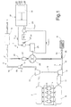
- numeral 1 designates an EGR apparatus providing recirculation of exhaust gases from an exhaust system 2 to an intake system 3 of an IC engine 4.
- Engine 4 is a turbocharged diesel engine, and includes a plurality of cylinders 5, an intake manifold 6 and an exhaust manifold 7 selectively connected to the cylinders via a known valve system, not shown.
- Air intake system 3 includes an air filter 9, a supercharging compressor 10 and an intercooler 11 cascading along an intake duct 12 connected to intake manifold 6.
- Exhaust system 2 includes a turbine 13, an exhaust aftertreatment apparatus 14 and a muffler 15 cascading along a an exhaust duct 16.
- the aftertreatment apparatus includes a catalytic converter 17 and a particulate matter (PM) filter 18.
- Compressor 10 and turbine 13 have respective rotors, not shown, that are rigidly connected to one another by a common shaft 19 in a conventional manner.
- the EGR apparatus of the present invention includes an EGR duct 20 connecting the exhaust duct 16 to the intake duct 12. More particularly, EGR duct 20 extends from an inlet branch point 21 at exhaust duct 16 located downstream of the aftertreatment apparatus 14, namely between aftertreatment apparatus 14 and muffler 15, to an outlet branch point 22 at intake duct 12 located upstream of compressor 10, namely between air filter 9 and compressor 10.
- the apparatus is therefore a so-called "low-pressure" EGR system, since the exhaust gas are not recirculated from the exhaust manifold, where typical parameters would be about 450°C and 2-3 ⁇ 10 5 Pa, but rather from downstream of the aftertratment apparatus 14, where temperature can be around 250°C and pressure about 1.05 to 1.2 ⁇ 10 5 Pa.
- the EGR apparatus 1 further includes an EGR cooler 23 and an EGR compressor 24 located along EGR duct 20 and aimed at controlling the recirculated exhaust gas temperature and mass flow rate, respectively.
- EGR cooler 23 is a conventional gas/liquid heat exchanger using engine cooling water as a cooling fluid for the exhaust gas. EGR cooler 23 can be also integrated inside the compressor casing in order to reduce the dimensions of the overall system.
- EGR compressor 24 is a rotary positive displacement compressor, e.g. a rotary vane compressor.
- EGR compressor 24 is driven by an electric motor 25 which is velocity-controlled by a control module 26 of the engine control unit (ECU) 27, so as to control the recirculated gas mass flow rate as described later on in grater detail.
- ECU engine control unit
- a velocity-controlled positive displacement EGR compressor 24 allows the EGR mass flow rate to be determined and controlled as a function of the emission control needs which, in turn, can be determined for each engine working conditions; in particular, an optimum EGR per cent value can be determined by the ECU, in a manner per se known, on the basis of a lookup table 28 as a function of operating parameters such as accelerator pedal position and speed (position derivate), engine rpm, and ambient temperature; such parameters are represented by signals S1, S2, S3, S4 that are input to ECU 27. Therefore, the target velocity of the compressor can be determined as a function of the engine working conditions, but is not dependent on the engine speed per se.
- the speed of motor 25 is controlled by varying the armature voltage.
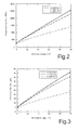
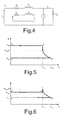
- the speed/armature voltage characteristic curve of motor 25 ( fig. 2 ) is quasi-linear. Since the EGR flow rate is proportional to the speed of compressor 24, a similar quasi-linear relationship exists - in steady conditions - between EGR mass flow rate request and the armature voltage of motor ( fig. 3 ). It is thus possible to control EGR mass flow rate by controlling the armature voltage of motor 25.
- an EGR flow rate request from the ECU can be seen as a speed set point for motor 25, and the variation in the compressor resisting torque can be seen as a disturbance.
- the resisting torque is subject to uncertainty, in particular because of friction, but can be estimated via a state observer that is based on a model of the electric motor/compressor unit, in order to provide a feedforward control for the electric motor that aims at a desired speed reference value.
- di a dt 1 L a ⁇ - R a ⁇ i a - K ⁇ ⁇ ⁇ ⁇ + V a t that represents the voltage balance across the armature circuit of the electric motor in accordance with the scheme of fig. 4 , where
- L c ⁇ B I V d p + V min ⁇ P del - P suc ⁇ m and therefore: C r ⁇ i ⁇ L c / 2 ⁇ ⁇ ⁇ ⁇ mech ⁇ ⁇ compr , pol ⁇ i ⁇ V max 2 ⁇ ⁇ ⁇ ⁇ mech ⁇ ⁇ compr , pol ⁇ m m - 1 ⁇ P suc t ⁇ ⁇ m - 1 + 1 ⁇ ⁇ P del t - P suc t ⁇ ⁇ m where:
- V a_ref C ⁇ r + ⁇ ⁇ C r K ⁇ ⁇ ⁇ R a + K ⁇ ⁇ ⁇ ⁇ t arg et
- the calculated nominal control voltage can be filtered via a compensator having one zero and one pole.
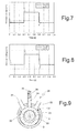
- spikes can be substituted by short overshooting step or stepped pulses as represented in fig. 8 , each pulse including one or more steps.
- a feedback speed control can be provided in order to produce a control system which is precise in term of speed set point, or for which the error in the electric motor-compressor speed is less that a fixed acceptable value.
- a conventional PID controller can be used.
- Gains K p and K i and K d can be adjusted to set the dynamic response of the assembly.
- a scheme of this control is represented in figure 1 .
- compressor 24 can be a single-vane, eccentric rotor compressor as shown schematically in fig 9 .
- Compressor 24 includes a casing 29 defining a cylindrical cavity 30 of axis A. Substantially radial suction port 31 and delivery port 32 communicate with cavity 30. Compressor 24 further includes an eccentric rotor 33 having an axis which is parallel but offset with respect to axis A. A single vane 34 is radially and slidingly housed in a seat 35 of casing 29 located between ports 31 and 32, and is biased by a spring 36 against rotor 33 so as to sealingly slide on the lateral surface 37 of rotor 33.
- This kind of compressor has proven to be particularly effective due to low friction and good dynamic behaviour with respect to conventional rotary vane compressors.
- a throttle valve 40 ( fig. 1 ) can be optionally included on intake duct 12, between air filter 9 and EGR outlet branch point 22, in order to lower the pressure value at point 22 and thus aid EGR flow or reduce the compressor work.
- a positive displacement compressor in the frame of a low-pressure EGR apparatus wherein EGR gas is fed to the inlet duct upstream from the supercharging compressor 10 provides for independent control of EGR flow rate, which can be set at any desired level in each operating condition of the engine, independently of the engine speed per se and the total exhaust gas flow rate.
- Positive displacement compressor 24, as such, has primarily transfer and metering functions, rather than pressurizing functions; to this end, it is important that branch point 22 is upstream of the supercharging compressor 10, where the pressure value is low and substantially constant.
- Positive displacement compressor 24 allows to dispense with the EGR valve.
- the part of the electric motor control based on a mathematical model estimating the future torque absorbed by the motor provides for a high responsiveness, with no need for look-up tables that require a lengthy experimentation to be set and do not take into account parameter drift during ageing of the system.
- the electric motor can be of different type, and the actuating quantity can be other than the voltage armature, e.g., current, duty cycle, frequency, etc. and in general any quantity that is suitable for the type of motor used.
- the feedback control can be of any known type, e.g. PI type.
- the evaluation of the EGR rate inside the ECU (as a function of engine speed and load) can be done also in different ways (model-based estimation, mixed lookup table / model-based, etc).
Landscapes
- Engineering & Computer Science (AREA)
- Mechanical Engineering (AREA)
- General Engineering & Computer Science (AREA)
- Chemical & Material Sciences (AREA)
- Combustion & Propulsion (AREA)
- Exhaust-Gas Circulating Devices (AREA)
- Supercharger (AREA)
- Output Control And Ontrol Of Special Type Engine (AREA)
Abstract
Description
- The present invention relates to an exhaust gas recirculation (EGR) apparatus for an internal combustion (IC) engine, particularly a turbocharged automotive diesel engine.
- It is well known that NOx emissions can be reduced by recirculating a portion of exhaust gases to engine intake. In present applications, EGR gas is routed through an EGR duct branching off the exhaust manifold upstream of the turbocharger turbine, and connected to the intake duct upstream of the turbocharger compressor. The EGR flow is ensured by the natural pressure difference between the exhaust manifold and the intake duct. The EGR flow rate and temperature are controlled via an EGR valve and an EGR cooler, respectively, located along the EGR duct.
- This arrangement is suitable for present applications, i.e. applications that are designed to overcome the present emission standards (e.g. Euro 4 requirements in Europe set a standard of 0.25 g/km for NOx). However, future standards are expected to be considerably stricter: in particular, NOx standards for Euro 5 are 20% lower than present standards. This requires that the EGR mass flow rate be considerably increased, up to expected values of 65% of the total exhaust flow rate. In connection with the new requirements, the know arrangement would bring about an unacceptable increase in the dimensions and weight of the EGR cooler and valve. Furthermore, an increased mass of the mobile parts of the EGR valve would cause unacceptably increased response times.
- Another problem connected with prior art systems of the aforesaid type, is that the EGR flow is still rich of precursors of particulate matter (PM) formation, such as oil droplets, hydrocarbons, chemically reactive PM. Therefore, this system is not suitable to comply with new PM requirements.
- In order to solve these problems, new EGR schemes have been proposed, in which the EGR duct branches off the exhaust manifold downstream of the exhaust aftertreatment unit. These systems are generally designated "low-pressure EGR". The low-pressure circuit scheme has two fundamental advantages: the recirculated exhaust gas is colder (and therefore there is no need for substantially increasing the cooler dimensions) and free from PM precursors. More generally speaking, an added benefit is also the recirculation of a gas which has a low level of hydrocarbons, being them reduced by the catalyst.
- However, the low-pressure systems suffer from a drawback consisting in an insufficient pressure differential between the ends of the EGR ducts. In facts, in certain operating conditions the pressure in the exhaust pipe downstream of the aftertreatment unit can be close to the pressure in the intake duct, and therefore natural flow of gas through the EGR duct may be impaired.
- Different solutions to this problems have been proposed, including the use of throttle devices in the exhaust duct downstream of the EGR duct inlet and in the air intake duct upstream of the EGR duct outlet, and the use of a compressor in the EGR duct. However, none of the known solutions has proven to be fully satisfactory in terms of control of the EGR mass flow rate and dynamic response.
- An object of the present invention is to devise an EGR control apparatus which is free from the drawbacks of the prior art.
- This scope is attained by an engine EGR apparatus as claimed in
claim 1. - A non-limiting embodiment of the present invention is described hereafter, with reference to the attached drawings in which:
-
Figure 1 is a scheme of an EGR apparatus according to the present invention; -
Figure 2 is a diagram representing the speed of an EGR compressor of the apparatus offigure 1 as a function of the armature voltage of the drive motor; -
Figure 3 is a diagram representing the mass flow rate of the EGR compressor as a function of the armature voltage of the motor; -
Figure 4 is a scheme of the motor equivalent circuit; -
Figure 5 is a diagram representing a first compressor working cycle; -
Figure 6 is a diagram representing a second compressor working cycle; -
Figure 7 is an exemplary diagram showing the motor armature voltage as a function of time; -
Figure 8 is another exemplary diagram showing the motor armature voltage as a function of time; -
Figure 9 is a schematic cross section of a preferred embodiment of the EGR compressor. - With reference to
figure 1 ,numeral 1 designates an EGR apparatus providing recirculation of exhaust gases from anexhaust system 2 to anintake system 3 of anIC engine 4. -
Engine 4 is a turbocharged diesel engine, and includes a plurality ofcylinders 5, anintake manifold 6 and an exhaust manifold 7 selectively connected to the cylinders via a known valve system, not shown. -
Air intake system 3 includes anair filter 9, asupercharging compressor 10 and anintercooler 11 cascading along anintake duct 12 connected tointake manifold 6. -
Exhaust system 2 includes aturbine 13, anexhaust aftertreatment apparatus 14 and amuffler 15 cascading along a anexhaust duct 16. The aftertreatment apparatus includes acatalytic converter 17 and a particulate matter (PM)filter 18. -
Compressor 10 andturbine 13 have respective rotors, not shown, that are rigidly connected to one another by acommon shaft 19 in a conventional manner. - The EGR apparatus of the present invention includes an
EGR duct 20 connecting theexhaust duct 16 to theintake duct 12. More particularly, EGRduct 20 extends from aninlet branch point 21 atexhaust duct 16 located downstream of theaftertreatment apparatus 14, namely betweenaftertreatment apparatus 14 andmuffler 15, to anoutlet branch point 22 atintake duct 12 located upstream ofcompressor 10, namely betweenair filter 9 andcompressor 10. The apparatus is therefore a so-called "low-pressure" EGR system, since the exhaust gas are not recirculated from the exhaust manifold, where typical parameters would be about 450°C and 2-3· 105 Pa, but rather from downstream of theaftertratment apparatus 14, where temperature can be around 250°C and pressure about 1.05 to 1.2·105 Pa. - The
EGR apparatus 1 further includes anEGR cooler 23 and anEGR compressor 24 located alongEGR duct 20 and aimed at controlling the recirculated exhaust gas temperature and mass flow rate, respectively. - EGR
cooler 23 is a conventional gas/liquid heat exchanger using engine cooling water as a cooling fluid for the exhaust gas. EGRcooler 23 can be also integrated inside the compressor casing in order to reduce the dimensions of the overall system. - EGR
compressor 24 is a rotary positive displacement compressor, e.g. a rotary vane compressor. EGRcompressor 24 is driven by anelectric motor 25 which is velocity-controlled by acontrol module 26 of the engine control unit (ECU) 27, so as to control the recirculated gas mass flow rate as described later on in grater detail. The use of a velocity-controlled positivedisplacement EGR compressor 24 allows the EGR mass flow rate to be determined and controlled as a function of the emission control needs which, in turn, can be determined for each engine working conditions; in particular, an optimum EGR per cent value can be determined by the ECU, in a manner per se known, on the basis of a lookup table 28 as a function of operating parameters such as accelerator pedal position and speed (position derivate), engine rpm, and ambient temperature; such parameters are represented by signals S1, S2, S3, S4 that are input toECU 27. Therefore, the target velocity of the compressor can be determined as a function of the engine working conditions, but is not dependent on the engine speed per se. - The speed of
motor 25 is controlled by varying the armature voltage. In steady conditions, the speed/armature voltage characteristic curve of motor 25 (fig. 2 ) is quasi-linear. Since the EGR flow rate is proportional to the speed ofcompressor 24, a similar quasi-linear relationship exists - in steady conditions - between EGR mass flow rate request and the armature voltage of motor (fig. 3 ). It is thus possible to control EGR mass flow rate by controlling the armature voltage ofmotor 25. - Clearly, in dynamic conditions a variation in EGR flow rate requires the compressor speed to change, and therefore brings about a variation in the compressor resisting torque.
- On the grounds of the above, and from a control standpoint, an EGR flow rate request from the ECU can be seen as a speed set point for
motor 25, and the variation in the compressor resisting torque can be seen as a disturbance. - The resisting torque is subject to uncertainty, in particular because of friction, but can be estimated via a state observer that is based on a model of the electric motor/compressor unit, in order to provide a feedforward control for the electric motor that aims at a desired speed reference value.
- A mathematical representation is given hereafter for the main elements (compressor, electric motor, control strategy) of the system. This could be done by following different approaches; the one presented here represents a suitable choice between model complexity and engineering purpose, being it clear that other models would be possible.
- In the case of a DC electric motor, actuated varying the voltage armature, an elementary model is defined by the following equations:

that represents the voltage balance across the armature circuit of the electric motor in accordance with the scheme offig. 4 , where - ia is the armature current,
- Ra is the armature equivalent resistance
- La is the armature equivalent inductance
- Va is the armature voltage;
- K Φ is the total magnetic flux, and
- ω is the motor speed;
and: - J is the moment of inertia of the rotating masses
- βc ω is the friction torque, and
- Cr is the resisting torque applied by
compressor 24. - The compressor resisting torque Cr depends on the polytropic work Lc performed by
compressor 24 on the fluid in each space between vanes. If there are i vanes:
where Pa is the power adsorbed bycompressor 24, η mech and η compr,pol are the mechanical and the polytropic compression efficiencies of the compressor. - With reference to the diagrams of
figure 5 and 6 , which represent the possible working cycles ofcompressor 24 depending on the delivery pressure level:
and therefore:
where: - Vmin, Vmax are the minimum and, respectively, maximum volume of the spaces between vanes;
- η compr, pol and η mech are the compression polytropic efficiency and the mechanical efficiency;
- Psuc is the pressure at suction side of the compressor;
- Pdel is the pressure at the delivery side of the compressor, i.e. at the
branch point 22; - ρ is the gas density; and
- m is the polytropic exponent.
- For simplicity of representation, η compr, pol and η mech have been considered equal to one hereinafter. However, proper values can be inserted easily into the following equations for a more comprehensive representation.
- Based on the above models, the equations of the state observer are the following:

where - ia_meas is the measured armature current
- Cr_nom is known from equation [5], and
- L1, L2 are feedback gains that determine the speed of the state observer
- Being:


and
gains L1 , and L2 can be estimated according to control theory. For instance, they can be determined by imposing the eigenvalues of the closed loop state matrix of the observer: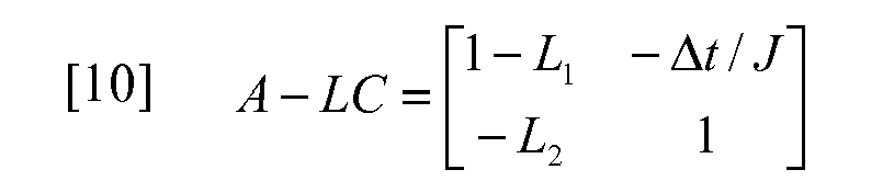
- On the grounds of the resisting torque value Cr + Δ Cr estimated according to the state observer described above and the motor target speed, a reference armature control voltage can be determined:

- In order to optimize the dynamic response of
motor 25, the calculated nominal control voltage can be filtered via a compensator having one zero and one pole. The compensator may be represented, in Laplace transform, by the following equation:
which, if the non-compensated armature reference voltage Va_ref is a step function, can be represented in the time domain by the diagram offig. 7 , where the compensated value Va_ff curve has spikes at each step front, each spike representing a rapidly decreasing, temporary voltage "overshooting" in the same direction as the desired voltage variation. - As an alternative, spikes can be substituted by short overshooting step or stepped pulses as represented in
fig. 8 , each pulse including one or more steps. - In addition to the above-described feedforward control, a feedback speed control can be provided in order to produce a control system which is precise in term of speed set point, or for which the error in the electric motor-compressor speed is less that a fixed acceptable value. For this purpose, a conventional PID controller can be used.
- In this case, the armature voltage can be provided, as follows:

where:
- Gains Kp and Ki and Kd can be adjusted to set the dynamic response of the assembly.
- A scheme of this control is represented in
figure 1 . - In this manner, optimum dynamic response is ensured by the feedforward control, and optimum accuracy is ensured by the feedback control.
- As an alternative, a further proportional feedback based on the difference between measured armature current ia_meas and calculated nominal armature current ia_nom can be added:

- According to an embodiment of the present invention,
compressor 24 can be a single-vane, eccentric rotor compressor as shown schematically infig 9 . -
Compressor 24 includes acasing 29 defining acylindrical cavity 30 of axis A. Substantiallyradial suction port 31 anddelivery port 32 communicate withcavity 30.Compressor 24 further includes aneccentric rotor 33 having an axis which is parallel but offset with respect to axis A. Asingle vane 34 is radially and slidingly housed in aseat 35 ofcasing 29 located betweenports spring 36 againstrotor 33 so as to sealingly slide on thelateral surface 37 ofrotor 33. - This kind of compressor has proven to be particularly effective due to low friction and good dynamic behaviour with respect to conventional rotary vane compressors.
- A throttle valve 40 (
fig. 1 ) can be optionally included onintake duct 12, betweenair filter 9 and EGRoutlet branch point 22, in order to lower the pressure value atpoint 22 and thus aid EGR flow or reduce the compressor work. - The use of a positive displacement compressor in the frame of a low-pressure EGR apparatus wherein EGR gas is fed to the inlet duct upstream from the supercharging
compressor 10 provides for independent control of EGR flow rate, which can be set at any desired level in each operating condition of the engine, independently of the engine speed per se and the total exhaust gas flow rate.Positive displacement compressor 24, as such, has primarily transfer and metering functions, rather than pressurizing functions; to this end, it is important thatbranch point 22 is upstream of the superchargingcompressor 10, where the pressure value is low and substantially constant. -
Positive displacement compressor 24 allows to dispense with the EGR valve. - The part of the electric motor control based on a mathematical model estimating the future torque absorbed by the motor provides for a high responsiveness, with no need for look-up tables that require a lengthy experimentation to be set and do not take into account parameter drift during ageing of the system.
- Clearly, the described EGR apparatus can be modified without departing from the scope of the claims.
- In particular, the electric motor can be of different type, and the actuating quantity can be other than the voltage armature, e.g., current, duty cycle, frequency, etc. and in general any quantity that is suitable for the type of motor used.
- The feedback control can be of any known type, e.g. PI type.
- The evaluation of the EGR rate inside the ECU (as a function of engine speed and load) can be done also in different ways (model-based estimation, mixed lookup table / model-based, etc...).

that represents the torque balance at the motor shaft, where the iron losses have been neglected and, in addition to already defined symbols,
Claims (9)
- An EGR apparatus for an IC engine (4) including an exhaust duct (16) directing a flow of exhaust gas from the IC engine through a turbine (13) and an aftertreatment device (14), an intake duct (12) directing a flow of intake air to the IC engine through a supercharging compressor (10), an EGR duct (20) connecting said exhaust duct (16) at a point downstream of said aftertreatment device (14) to said intake duct (12) at a point upstream of said compressor (10), said EGR apparatus including an EGR cooler (23) and a positive displacement compressor (24) along said EGR duct (20), an electric motor (25) driving said positive displacement compressor (24), and a control means (26) controlling said motor (25) in response to an EGR flow rate request depending on operating parameters of said IC engine (4).
- An EGR apparatus as claimed in claim 1, characterised in that said electric motor (25) is a DC motor that is velocity-controlled by varying the armature voltage.
- An EGR apparatus as claimed in claim 1, characterised in that said control means (26) is model-based.
- An EGR apparatus as claimed in any of the preceding claims, characterised in that said control means includes a state observer which estimates the resisting torque of said positive displacement compressor (24).
- An EGR apparatus as claimed in claim 4, characterised in that said control means include a control voltage compensator producing voltage overshooting at voltage transients in the same direction as voltage changes.
- An EGR apparatus as claimed in claim 5, characterised in that said control voltage compensator has a zero and a pole.
- An EGR apparatus as claimed in any of the preceding claims, characterised in that said control means include a model-based feedforward control means and a feedback control means.
- An EGR as claimed in claim 7, characterised in that said feedback control means is of PI type.
- An EGR as claimed in claim 7, characterised in that said feedback control means is of PID type.
Applications Claiming Priority (1)
| Application Number | Priority Date | Filing Date | Title |
|---|---|---|---|
| PCT/ES2006/070189 WO2008071810A1 (en) | 2006-12-11 | 2006-12-11 | Internal combustion engine egr apparatus |
Publications (2)
| Publication Number | Publication Date |
|---|---|
| EP2096295A1 true EP2096295A1 (en) | 2009-09-02 |
| EP2096295B1 EP2096295B1 (en) | 2011-03-09 |
Family
ID=37865791
Family Applications (1)
| Application Number | Title | Priority Date | Filing Date |
|---|---|---|---|
| EP06841796A Not-in-force EP2096295B1 (en) | 2006-12-11 | 2006-12-11 | Internal combustion engine egr apparatus |
Country Status (8)
| Country | Link |
|---|---|
| US (1) | US20120137679A1 (en) |
| EP (1) | EP2096295B1 (en) |
| JP (1) | JP4979773B2 (en) |
| CN (1) | CN101631947B (en) |
| AT (1) | ATE501350T1 (en) |
| BR (1) | BRPI0622194A2 (en) |
| DE (1) | DE602006020641D1 (en) |
| WO (1) | WO2008071810A1 (en) |
Cited By (3)
| Publication number | Priority date | Publication date | Assignee | Title |
|---|---|---|---|---|
| FR3057622A1 (en) * | 2016-10-14 | 2018-04-20 | Valeo Systemes De Controle Moteur | ENERGY RECOVERY SYSTEM WITH COOLING SYSTEM |
| IT201700044961A1 (en) * | 2017-04-26 | 2018-10-26 | Fpt Motorenforschung Ag | MOTOR SYSTEM WITH INTERNAL COMBUSTION AND FUNCTIONING OF THE SAME |
| WO2019141767A3 (en) * | 2018-01-17 | 2019-08-29 | Eaton Intelligent Power Limited | Method of operating an exhaust gas recirculation pump |
Families Citing this family (11)
| Publication number | Priority date | Publication date | Assignee | Title |
|---|---|---|---|---|
| US8549854B2 (en) * | 2010-05-18 | 2013-10-08 | Achates Power, Inc. | EGR constructions for opposed-piston engines |
| JP2012087636A (en) * | 2010-10-15 | 2012-05-10 | Nissan Motor Co Ltd | Exhaust gas recirculation control device for internal combustion engine |
| US20130174548A1 (en) | 2011-05-16 | 2013-07-11 | Achates Power, Inc. | EGR for a Two-Stroke Cycle Engine without a Supercharger |
| DE102016219097A1 (en) * | 2016-09-30 | 2018-04-05 | Ford Global Technologies, Llc | Internal combustion engine with exhaust gas recirculation and method for operating such an internal combustion engine |
| US10138822B2 (en) | 2016-12-16 | 2018-11-27 | Ford Global Technologies, Llc | Systems and methods for a split exhaust engine system |
| US10012159B1 (en) * | 2016-12-16 | 2018-07-03 | Ford Global Technologies, Llc | Systems and methods for a split exhaust engine system |
| CN106948975A (en) * | 2017-03-31 | 2017-07-14 | 哈尔滨工程大学 | A kind of diesel engine EGR device and its implementation based on large, medium and small three turbocharger |
| CN107401449A (en) * | 2017-09-06 | 2017-11-28 | 哈尔滨工程大学 | Diesel exhaust waste heat cools down ECR fan pressure charging system |
| WO2020001780A1 (en) * | 2018-06-29 | 2020-01-02 | Volvo Truck Corporation | An internal combustion engine |
| CN113969851A (en) * | 2021-09-28 | 2022-01-25 | 东风商用车有限公司 | EGR (exhaust gas recirculation) rate driving capability improving system and control method |
| CN116877264A (en) * | 2023-07-17 | 2023-10-13 | 中国北方发动机研究所 | Two-stage supercharger with cooling structure |
Family Cites Families (14)
| Publication number | Priority date | Publication date | Assignee | Title |
|---|---|---|---|---|
| JPH0742939B2 (en) * | 1985-10-07 | 1995-05-15 | 株式会社日立製作所 | Torque controlled compressor |
| JPH10103165A (en) | 1996-09-24 | 1998-04-21 | Ishikawajima Harima Heavy Ind Co Ltd | Exhaust gas recirculation system for turbocharged engines |
| US6164071A (en) * | 1997-09-08 | 2000-12-26 | Cummins Engine Company, Inc. | EGR delivery and control system using dedicated full authority compressor |
| JP2000053296A (en) * | 1998-08-07 | 2000-02-22 | Taisei Tekkosho:Kk | Driving method and mechanism for roll manufacturing device |
| US6192686B1 (en) * | 1999-03-22 | 2001-02-27 | Caterpillar Inc. | Exhaust gas recirculation system |
| JP3998861B2 (en) * | 1999-06-16 | 2007-10-31 | 株式会社小松製作所 | Exhaust gas recirculation device and control method thereof |
| EP1069314A1 (en) * | 1999-07-16 | 2001-01-17 | Abb Research Ltd. | Control of a compressor unit |
| US6775646B1 (en) * | 2000-02-23 | 2004-08-10 | Agilent Technologies, Inc. | Excitation signal and radial basis function methods for use in extraction of nonlinear black-box behavioral models |
| JP4281257B2 (en) * | 2000-06-29 | 2009-06-17 | トヨタ自動車株式会社 | Engine valve drive control device |
| JP2002332919A (en) * | 2001-02-26 | 2002-11-22 | Mitsubishi Heavy Ind Ltd | Exhaust gas recirculation system |
| JP4123960B2 (en) * | 2003-02-14 | 2008-07-23 | 日産自動車株式会社 | Control device for hybrid vehicle |
| JP2004291686A (en) * | 2003-03-25 | 2004-10-21 | Hitachi Unisia Automotive Ltd | Power steering device |
| JP4207695B2 (en) * | 2003-07-02 | 2009-01-14 | マツダ株式会社 | EGR control device for engine |
| JP2006242063A (en) * | 2005-03-02 | 2006-09-14 | Denso Corp | Control device for an internal combustion engine with a supercharger |
-
2006
- 2006-12-11 EP EP06841796A patent/EP2096295B1/en not_active Not-in-force
- 2006-12-11 WO PCT/ES2006/070189 patent/WO2008071810A1/en not_active Ceased
- 2006-12-11 AT AT06841796T patent/ATE501350T1/en not_active IP Right Cessation
- 2006-12-11 US US12/448,167 patent/US20120137679A1/en not_active Abandoned
- 2006-12-11 DE DE602006020641T patent/DE602006020641D1/en active Active
- 2006-12-11 BR BRPI0622194-7A patent/BRPI0622194A2/en not_active IP Right Cessation
- 2006-12-11 JP JP2009540795A patent/JP4979773B2/en not_active Expired - Fee Related
- 2006-12-11 CN CN2006800569069A patent/CN101631947B/en not_active Expired - Fee Related
Non-Patent Citations (1)
| Title |
|---|
| See references of WO2008071810A1 * |
Cited By (8)
| Publication number | Priority date | Publication date | Assignee | Title |
|---|---|---|---|---|
| FR3057622A1 (en) * | 2016-10-14 | 2018-04-20 | Valeo Systemes De Controle Moteur | ENERGY RECOVERY SYSTEM WITH COOLING SYSTEM |
| IT201700044961A1 (en) * | 2017-04-26 | 2018-10-26 | Fpt Motorenforschung Ag | MOTOR SYSTEM WITH INTERNAL COMBUSTION AND FUNCTIONING OF THE SAME |
| EP3396131A1 (en) * | 2017-04-26 | 2018-10-31 | FPT Motorenforschung AG | Internal combustion engine arrangement and operation thereof |
| EP3800336A1 (en) * | 2017-04-26 | 2021-04-07 | FPT Motorenforschung AG | Internal combustion engine arrangement and operation thereof |
| WO2019141767A3 (en) * | 2018-01-17 | 2019-08-29 | Eaton Intelligent Power Limited | Method of operating an exhaust gas recirculation pump |
| US11668269B2 (en) | 2018-01-17 | 2023-06-06 | Eaton Intelligent Power Limited | EGR pump system and control method of EGR pump |
| US12006896B2 (en) | 2018-01-17 | 2024-06-11 | Eaton Intelligent Power Limited | EGR pump system and control method of EGR pump |
| US12188437B2 (en) | 2018-01-17 | 2025-01-07 | Eaton Intelligent Power Limited | EGR pump system and control method of EGR pump |
Also Published As
| Publication number | Publication date |
|---|---|
| CN101631947A (en) | 2010-01-20 |
| CN101631947B (en) | 2012-02-08 |
| ATE501350T1 (en) | 2011-03-15 |
| WO2008071810A1 (en) | 2008-06-19 |
| DE602006020641D1 (en) | 2011-04-21 |
| JP2010512487A (en) | 2010-04-22 |
| US20120137679A1 (en) | 2012-06-07 |
| JP4979773B2 (en) | 2012-07-18 |
| EP2096295B1 (en) | 2011-03-09 |
| BRPI0622194A2 (en) | 2012-01-03 |
Similar Documents
| Publication | Publication Date | Title |
|---|---|---|
| US10815918B2 (en) | Controller and control method for supercharger-equipped internal combustion engine | |
| EP2096295B1 (en) | Internal combustion engine egr apparatus | |
| RU2600842C2 (en) | Turbo-compound supercharged engine unit | |
| US8522756B2 (en) | Interstage exhaust gas recirculation system for a dual turbocharged engine having a turbogenerator system | |
| US8522757B2 (en) | Metering exhaust gas recirculation system for a dual turbocharged engine having a turbogenerator system | |
| US10054038B2 (en) | Method for controlling a dual-supercharged combustion engine | |
| JP4741678B2 (en) | Diesel engine with supercharger | |
| US8393152B2 (en) | Electric supercharger | |
| CN108026866B (en) | Natural Gas Engine System with Improved Transient Response | |
| RU144414U1 (en) | ENERGY REGENERATION SYSTEM FOR INTERNAL COMBUSTION ENGINE | |
| US20130276443A1 (en) | System and method for controlling an exhaust-braking engine maneuver | |
| EP3814618B1 (en) | A method of operating a four stroke internal combustion engine system | |
| EP2749757A1 (en) | Method and apparatus for controlling a twin scroll turbocharger with variable geometry depending on the exhaust gas recirculation | |
| JPH1162720A (en) | Engine EGR control device | |
| EP3994345B1 (en) | An internal combustion engine system | |
| JP2018076838A (en) | Control device of internal combustion engine | |
| JP2018096351A (en) | Engine supercharger |
Legal Events
| Date | Code | Title | Description |
|---|---|---|---|
| PUAI | Public reference made under article 153(3) epc to a published international application that has entered the european phase |
Free format text: ORIGINAL CODE: 0009012 |
|
| 17P | Request for examination filed |
Effective date: 20090630 |
|
| AK | Designated contracting states |
Kind code of ref document: A1 Designated state(s): AT BE BG CH CY CZ DE DK EE ES FI FR GB GR HU IE IS IT LI LT LU LV MC NL PL PT RO SE SI SK TR |
|
| 17Q | First examination report despatched |
Effective date: 20090918 |
|
| DAX | Request for extension of the european patent (deleted) | ||
| GRAP | Despatch of communication of intention to grant a patent |
Free format text: ORIGINAL CODE: EPIDOSNIGR1 |
|
| GRAS | Grant fee paid |
Free format text: ORIGINAL CODE: EPIDOSNIGR3 |
|
| RAP1 | Party data changed (applicant data changed or rights of an application transferred) |
Owner name: BORGWARNER EMISSION SYSTEMS SPAIN, S.L. |
|
| GRAA | (expected) grant |
Free format text: ORIGINAL CODE: 0009210 |
|
| RAP3 | Party data changed (applicant data changed or rights of an application transferred) |
Owner name: BORGWARNER EMISSIONS SYSTEMS SPAIN, S.L. |
|
| AK | Designated contracting states |
Kind code of ref document: B1 Designated state(s): AT BE BG CH CY CZ DE DK EE ES FI FR GB GR HU IE IS IT LI LT LU LV MC NL PL PT RO SE SI SK TR |
|
| REG | Reference to a national code |
Ref country code: GB Ref legal event code: FG4D |
|
| REG | Reference to a national code |
Ref country code: CH Ref legal event code: EP |
|
| REG | Reference to a national code |
Ref country code: IE Ref legal event code: FG4D |
|
| REF | Corresponds to: |
Ref document number: 602006020641 Country of ref document: DE Date of ref document: 20110421 Kind code of ref document: P |
|
| REG | Reference to a national code |
Ref country code: DE Ref legal event code: R096 Ref document number: 602006020641 Country of ref document: DE Effective date: 20110421 |
|
| REG | Reference to a national code |
Ref country code: NL Ref legal event code: VDEP Effective date: 20110309 |
|
| PG25 | Lapsed in a contracting state [announced via postgrant information from national office to epo] |
Ref country code: ES Free format text: LAPSE BECAUSE OF FAILURE TO SUBMIT A TRANSLATION OF THE DESCRIPTION OR TO PAY THE FEE WITHIN THE PRESCRIBED TIME-LIMIT Effective date: 20110620 Ref country code: LT Free format text: LAPSE BECAUSE OF FAILURE TO SUBMIT A TRANSLATION OF THE DESCRIPTION OR TO PAY THE FEE WITHIN THE PRESCRIBED TIME-LIMIT Effective date: 20110309 Ref country code: GR Free format text: LAPSE BECAUSE OF FAILURE TO SUBMIT A TRANSLATION OF THE DESCRIPTION OR TO PAY THE FEE WITHIN THE PRESCRIBED TIME-LIMIT Effective date: 20110610 Ref country code: SE Free format text: LAPSE BECAUSE OF FAILURE TO SUBMIT A TRANSLATION OF THE DESCRIPTION OR TO PAY THE FEE WITHIN THE PRESCRIBED TIME-LIMIT Effective date: 20110309 Ref country code: LV Free format text: LAPSE BECAUSE OF FAILURE TO SUBMIT A TRANSLATION OF THE DESCRIPTION OR TO PAY THE FEE WITHIN THE PRESCRIBED TIME-LIMIT Effective date: 20110309 |
|
| LTIE | Lt: invalidation of european patent or patent extension |
Effective date: 20110309 |
|
| PG25 | Lapsed in a contracting state [announced via postgrant information from national office to epo] |
Ref country code: FI Free format text: LAPSE BECAUSE OF FAILURE TO SUBMIT A TRANSLATION OF THE DESCRIPTION OR TO PAY THE FEE WITHIN THE PRESCRIBED TIME-LIMIT Effective date: 20110309 Ref country code: SI Free format text: LAPSE BECAUSE OF FAILURE TO SUBMIT A TRANSLATION OF THE DESCRIPTION OR TO PAY THE FEE WITHIN THE PRESCRIBED TIME-LIMIT Effective date: 20110309 Ref country code: CY Free format text: LAPSE BECAUSE OF FAILURE TO SUBMIT A TRANSLATION OF THE DESCRIPTION OR TO PAY THE FEE WITHIN THE PRESCRIBED TIME-LIMIT Effective date: 20110309 Ref country code: AT Free format text: LAPSE BECAUSE OF FAILURE TO SUBMIT A TRANSLATION OF THE DESCRIPTION OR TO PAY THE FEE WITHIN THE PRESCRIBED TIME-LIMIT Effective date: 20110309 Ref country code: NL Free format text: LAPSE BECAUSE OF FAILURE TO SUBMIT A TRANSLATION OF THE DESCRIPTION OR TO PAY THE FEE WITHIN THE PRESCRIBED TIME-LIMIT Effective date: 20110309 Ref country code: BG Free format text: LAPSE BECAUSE OF FAILURE TO SUBMIT A TRANSLATION OF THE DESCRIPTION OR TO PAY THE FEE WITHIN THE PRESCRIBED TIME-LIMIT Effective date: 20110609 |
|
| PG25 | Lapsed in a contracting state [announced via postgrant information from national office to epo] |
Ref country code: BE Free format text: LAPSE BECAUSE OF FAILURE TO SUBMIT A TRANSLATION OF THE DESCRIPTION OR TO PAY THE FEE WITHIN THE PRESCRIBED TIME-LIMIT Effective date: 20110309 |
|
| PG25 | Lapsed in a contracting state [announced via postgrant information from national office to epo] |
Ref country code: PT Free format text: LAPSE BECAUSE OF FAILURE TO SUBMIT A TRANSLATION OF THE DESCRIPTION OR TO PAY THE FEE WITHIN THE PRESCRIBED TIME-LIMIT Effective date: 20110711 Ref country code: EE Free format text: LAPSE BECAUSE OF FAILURE TO SUBMIT A TRANSLATION OF THE DESCRIPTION OR TO PAY THE FEE WITHIN THE PRESCRIBED TIME-LIMIT Effective date: 20110309 |
|
| PG25 | Lapsed in a contracting state [announced via postgrant information from national office to epo] |
Ref country code: CZ Free format text: LAPSE BECAUSE OF FAILURE TO SUBMIT A TRANSLATION OF THE DESCRIPTION OR TO PAY THE FEE WITHIN THE PRESCRIBED TIME-LIMIT Effective date: 20110309 Ref country code: RO Free format text: LAPSE BECAUSE OF FAILURE TO SUBMIT A TRANSLATION OF THE DESCRIPTION OR TO PAY THE FEE WITHIN THE PRESCRIBED TIME-LIMIT Effective date: 20110309 Ref country code: SK Free format text: LAPSE BECAUSE OF FAILURE TO SUBMIT A TRANSLATION OF THE DESCRIPTION OR TO PAY THE FEE WITHIN THE PRESCRIBED TIME-LIMIT Effective date: 20110309 Ref country code: IS Free format text: LAPSE BECAUSE OF FAILURE TO SUBMIT A TRANSLATION OF THE DESCRIPTION OR TO PAY THE FEE WITHIN THE PRESCRIBED TIME-LIMIT Effective date: 20110709 |
|
| PLBE | No opposition filed within time limit |
Free format text: ORIGINAL CODE: 0009261 |
|
| STAA | Information on the status of an ep patent application or granted ep patent |
Free format text: STATUS: NO OPPOSITION FILED WITHIN TIME LIMIT |
|
| 26N | No opposition filed |
Effective date: 20111212 |
|
| PG25 | Lapsed in a contracting state [announced via postgrant information from national office to epo] |
Ref country code: PL Free format text: LAPSE BECAUSE OF FAILURE TO SUBMIT A TRANSLATION OF THE DESCRIPTION OR TO PAY THE FEE WITHIN THE PRESCRIBED TIME-LIMIT Effective date: 20110309 Ref country code: DK Free format text: LAPSE BECAUSE OF FAILURE TO SUBMIT A TRANSLATION OF THE DESCRIPTION OR TO PAY THE FEE WITHIN THE PRESCRIBED TIME-LIMIT Effective date: 20110309 |
|
| REG | Reference to a national code |
Ref country code: DE Ref legal event code: R097 Ref document number: 602006020641 Country of ref document: DE Effective date: 20111212 |
|
| PG25 | Lapsed in a contracting state [announced via postgrant information from national office to epo] |
Ref country code: IT Free format text: LAPSE BECAUSE OF FAILURE TO SUBMIT A TRANSLATION OF THE DESCRIPTION OR TO PAY THE FEE WITHIN THE PRESCRIBED TIME-LIMIT Effective date: 20110309 |
|
| PG25 | Lapsed in a contracting state [announced via postgrant information from national office to epo] |
Ref country code: MC Free format text: LAPSE BECAUSE OF NON-PAYMENT OF DUE FEES Effective date: 20111231 |
|
| REG | Reference to a national code |
Ref country code: CH Ref legal event code: PL |
|
| GBPC | Gb: european patent ceased through non-payment of renewal fee |
Effective date: 20111211 |
|
| REG | Reference to a national code |
Ref country code: IE Ref legal event code: MM4A |
|
| PG25 | Lapsed in a contracting state [announced via postgrant information from national office to epo] |
Ref country code: LI Free format text: LAPSE BECAUSE OF NON-PAYMENT OF DUE FEES Effective date: 20111231 Ref country code: CH Free format text: LAPSE BECAUSE OF NON-PAYMENT OF DUE FEES Effective date: 20111231 Ref country code: GB Free format text: LAPSE BECAUSE OF NON-PAYMENT OF DUE FEES Effective date: 20111211 Ref country code: IE Free format text: LAPSE BECAUSE OF NON-PAYMENT OF DUE FEES Effective date: 20111211 |
|
| PG25 | Lapsed in a contracting state [announced via postgrant information from national office to epo] |
Ref country code: LU Free format text: LAPSE BECAUSE OF NON-PAYMENT OF DUE FEES Effective date: 20111211 |
|
| PG25 | Lapsed in a contracting state [announced via postgrant information from national office to epo] |
Ref country code: TR Free format text: LAPSE BECAUSE OF FAILURE TO SUBMIT A TRANSLATION OF THE DESCRIPTION OR TO PAY THE FEE WITHIN THE PRESCRIBED TIME-LIMIT Effective date: 20110309 |
|
| PG25 | Lapsed in a contracting state [announced via postgrant information from national office to epo] |
Ref country code: HU Free format text: LAPSE BECAUSE OF FAILURE TO SUBMIT A TRANSLATION OF THE DESCRIPTION OR TO PAY THE FEE WITHIN THE PRESCRIBED TIME-LIMIT Effective date: 20110309 |
|
| REG | Reference to a national code |
Ref country code: DE Ref legal event code: R082 Ref document number: 602006020641 Country of ref document: DE Representative=s name: SAMSON & PARTNER, PATENTANWAELTE, DE |
|
| REG | Reference to a national code |
Ref country code: DE Ref legal event code: R081 Ref document number: 602006020641 Country of ref document: DE Owner name: BORGWARNER EMISSIONS SYSTEMS SPAIN, S.L.UNIPER, ES Free format text: FORMER OWNER: BORGWARNER EMISSIONS SYSTEMS SPAIN, S.L., VIGO, PONTEVEDRA, ES Effective date: 20150121 Ref country code: DE Ref legal event code: R082 Ref document number: 602006020641 Country of ref document: DE Representative=s name: SAMSON & PARTNER, PATENTANWAELTE, DE Effective date: 20150121 Ref country code: DE Ref legal event code: R082 Ref document number: 602006020641 Country of ref document: DE Representative=s name: SAMSON & PARTNER PATENTANWAELTE MBB, DE Effective date: 20150121 |
|
| PGFP | Annual fee paid to national office [announced via postgrant information from national office to epo] |
Ref country code: FR Payment date: 20141124 Year of fee payment: 9 |
|
| REG | Reference to a national code |
Ref country code: FR Ref legal event code: CD Owner name: BORGWARNER EMISSIONS SYSTEMS SPAIN, S.L. UNIPE, ES Effective date: 20150318 Ref country code: FR Ref legal event code: CJ Effective date: 20150318 |
|
| REG | Reference to a national code |
Ref country code: FR Ref legal event code: ST Effective date: 20160831 |
|
| PG25 | Lapsed in a contracting state [announced via postgrant information from national office to epo] |
Ref country code: FR Free format text: LAPSE BECAUSE OF NON-PAYMENT OF DUE FEES Effective date: 20151231 |
|
| PGFP | Annual fee paid to national office [announced via postgrant information from national office to epo] |
Ref country code: DE Payment date: 20171221 Year of fee payment: 12 |
|
| REG | Reference to a national code |
Ref country code: DE Ref legal event code: R119 Ref document number: 602006020641 Country of ref document: DE |
|
| PG25 | Lapsed in a contracting state [announced via postgrant information from national office to epo] |
Ref country code: DE Free format text: LAPSE BECAUSE OF NON-PAYMENT OF DUE FEES Effective date: 20190702 |