EP2096192A1 - Backside coating prevention device. - Google Patents
Backside coating prevention device. Download PDFInfo
- Publication number
- EP2096192A1 EP2096192A1 EP08160908A EP08160908A EP2096192A1 EP 2096192 A1 EP2096192 A1 EP 2096192A1 EP 08160908 A EP08160908 A EP 08160908A EP 08160908 A EP08160908 A EP 08160908A EP 2096192 A1 EP2096192 A1 EP 2096192A1
- Authority
- EP
- European Patent Office
- Prior art keywords
- coating
- barrier gas
- plate
- coating chamber
- transport system
- Prior art date
- Legal status (The legal status is an assumption and is not a legal conclusion. Google has not performed a legal analysis and makes no representation as to the accuracy of the status listed.)
- Withdrawn
Links
- 238000000576 coating method Methods 0.000 title claims abstract description 365
- 239000011248 coating agent Substances 0.000 title claims abstract description 346
- 230000002265 prevention Effects 0.000 title claims abstract description 78
- 239000000758 substrate Substances 0.000 claims abstract description 415
- 230000004888 barrier function Effects 0.000 claims abstract description 184
- 239000000463 material Substances 0.000 claims abstract description 44
- 230000003405 preventing effect Effects 0.000 claims abstract description 12
- 239000011521 glass Substances 0.000 claims description 219
- 238000004544 sputter deposition Methods 0.000 claims description 45
- 238000000034 method Methods 0.000 claims description 23
- 238000007599 discharging Methods 0.000 claims description 3
- 238000001771 vacuum deposition Methods 0.000 claims 2
- 239000007789 gas Substances 0.000 description 141
- 239000002245 particle Substances 0.000 description 31
- 238000009434 installation Methods 0.000 description 17
- 238000013461 design Methods 0.000 description 12
- 238000012986 modification Methods 0.000 description 10
- 230000004048 modification Effects 0.000 description 10
- 238000007665 sagging Methods 0.000 description 5
- 239000010409 thin film Substances 0.000 description 5
- 239000010408 film Substances 0.000 description 4
- 239000010935 stainless steel Substances 0.000 description 4
- 229910001220 stainless steel Inorganic materials 0.000 description 4
- 238000010586 diagram Methods 0.000 description 3
- 230000000694 effects Effects 0.000 description 3
- 239000000203 mixture Substances 0.000 description 3
- 239000013077 target material Substances 0.000 description 3
- 229910021417 amorphous silicon Inorganic materials 0.000 description 2
- 238000001816 cooling Methods 0.000 description 2
- 238000000151 deposition Methods 0.000 description 2
- 230000008021 deposition Effects 0.000 description 2
- 230000008020 evaporation Effects 0.000 description 2
- 238000001704 evaporation Methods 0.000 description 2
- 238000009501 film coating Methods 0.000 description 2
- 238000004519 manufacturing process Methods 0.000 description 2
- 239000002184 metal Substances 0.000 description 2
- 229910052751 metal Inorganic materials 0.000 description 2
- 229910021424 microcrystalline silicon Inorganic materials 0.000 description 2
- 229910000838 Al alloy Inorganic materials 0.000 description 1
- XEEYBQQBJWHFJM-UHFFFAOYSA-N Iron Chemical compound [Fe] XEEYBQQBJWHFJM-UHFFFAOYSA-N 0.000 description 1
- 229910045601 alloy Inorganic materials 0.000 description 1
- 239000000956 alloy Substances 0.000 description 1
- 229910052782 aluminium Inorganic materials 0.000 description 1
- XAGFODPZIPBFFR-UHFFFAOYSA-N aluminium Chemical compound [Al] XAGFODPZIPBFFR-UHFFFAOYSA-N 0.000 description 1
- 238000004140 cleaning Methods 0.000 description 1
- 238000011109 contamination Methods 0.000 description 1
- 239000005329 float glass Substances 0.000 description 1
- 239000011261 inert gas Substances 0.000 description 1
- 150000002500 ions Chemical class 0.000 description 1
- 238000012423 maintenance Methods 0.000 description 1
- 150000002739 metals Chemical class 0.000 description 1
- 239000002985 plastic film Substances 0.000 description 1
- 229920006255 plastic film Polymers 0.000 description 1
- 238000012545 processing Methods 0.000 description 1
- 230000001737 promoting effect Effects 0.000 description 1
- HUAUNKAZQWMVFY-UHFFFAOYSA-M sodium;oxocalcium;hydroxide Chemical compound [OH-].[Na+].[Ca]=O HUAUNKAZQWMVFY-UHFFFAOYSA-M 0.000 description 1
Images





Classifications
-
- C—CHEMISTRY; METALLURGY
- C23—COATING METALLIC MATERIAL; COATING MATERIAL WITH METALLIC MATERIAL; CHEMICAL SURFACE TREATMENT; DIFFUSION TREATMENT OF METALLIC MATERIAL; COATING BY VACUUM EVAPORATION, BY SPUTTERING, BY ION IMPLANTATION OR BY CHEMICAL VAPOUR DEPOSITION, IN GENERAL; INHIBITING CORROSION OF METALLIC MATERIAL OR INCRUSTATION IN GENERAL
- C23C—COATING METALLIC MATERIAL; COATING MATERIAL WITH METALLIC MATERIAL; SURFACE TREATMENT OF METALLIC MATERIAL BY DIFFUSION INTO THE SURFACE, BY CHEMICAL CONVERSION OR SUBSTITUTION; COATING BY VACUUM EVAPORATION, BY SPUTTERING, BY ION IMPLANTATION OR BY CHEMICAL VAPOUR DEPOSITION, IN GENERAL
- C23C14/00—Coating by vacuum evaporation, by sputtering or by ion implantation of the coating forming material
- C23C14/04—Coating on selected surface areas, e.g. using masks
- C23C14/042—Coating on selected surface areas, e.g. using masks using masks
-
- C—CHEMISTRY; METALLURGY
- C23—COATING METALLIC MATERIAL; COATING MATERIAL WITH METALLIC MATERIAL; CHEMICAL SURFACE TREATMENT; DIFFUSION TREATMENT OF METALLIC MATERIAL; COATING BY VACUUM EVAPORATION, BY SPUTTERING, BY ION IMPLANTATION OR BY CHEMICAL VAPOUR DEPOSITION, IN GENERAL; INHIBITING CORROSION OF METALLIC MATERIAL OR INCRUSTATION IN GENERAL
- C23C—COATING METALLIC MATERIAL; COATING MATERIAL WITH METALLIC MATERIAL; SURFACE TREATMENT OF METALLIC MATERIAL BY DIFFUSION INTO THE SURFACE, BY CHEMICAL CONVERSION OR SUBSTITUTION; COATING BY VACUUM EVAPORATION, BY SPUTTERING, BY ION IMPLANTATION OR BY CHEMICAL VAPOUR DEPOSITION, IN GENERAL
- C23C14/00—Coating by vacuum evaporation, by sputtering or by ion implantation of the coating forming material
- C23C14/22—Coating by vacuum evaporation, by sputtering or by ion implantation of the coating forming material characterised by the process of coating
- C23C14/56—Apparatus specially adapted for continuous coating; Arrangements for maintaining the vacuum, e.g. vacuum locks
-
- C—CHEMISTRY; METALLURGY
- C23—COATING METALLIC MATERIAL; COATING MATERIAL WITH METALLIC MATERIAL; CHEMICAL SURFACE TREATMENT; DIFFUSION TREATMENT OF METALLIC MATERIAL; COATING BY VACUUM EVAPORATION, BY SPUTTERING, BY ION IMPLANTATION OR BY CHEMICAL VAPOUR DEPOSITION, IN GENERAL; INHIBITING CORROSION OF METALLIC MATERIAL OR INCRUSTATION IN GENERAL
- C23C—COATING METALLIC MATERIAL; COATING MATERIAL WITH METALLIC MATERIAL; SURFACE TREATMENT OF METALLIC MATERIAL BY DIFFUSION INTO THE SURFACE, BY CHEMICAL CONVERSION OR SUBSTITUTION; COATING BY VACUUM EVAPORATION, BY SPUTTERING, BY ION IMPLANTATION OR BY CHEMICAL VAPOUR DEPOSITION, IN GENERAL
- C23C14/00—Coating by vacuum evaporation, by sputtering or by ion implantation of the coating forming material
- C23C14/22—Coating by vacuum evaporation, by sputtering or by ion implantation of the coating forming material characterised by the process of coating
- C23C14/56—Apparatus specially adapted for continuous coating; Arrangements for maintaining the vacuum, e.g. vacuum locks
- C23C14/564—Means for minimising impurities in the coating chamber such as dust, moisture, residual gases
-
- C—CHEMISTRY; METALLURGY
- C23—COATING METALLIC MATERIAL; COATING MATERIAL WITH METALLIC MATERIAL; CHEMICAL SURFACE TREATMENT; DIFFUSION TREATMENT OF METALLIC MATERIAL; COATING BY VACUUM EVAPORATION, BY SPUTTERING, BY ION IMPLANTATION OR BY CHEMICAL VAPOUR DEPOSITION, IN GENERAL; INHIBITING CORROSION OF METALLIC MATERIAL OR INCRUSTATION IN GENERAL
- C23C—COATING METALLIC MATERIAL; COATING MATERIAL WITH METALLIC MATERIAL; SURFACE TREATMENT OF METALLIC MATERIAL BY DIFFUSION INTO THE SURFACE, BY CHEMICAL CONVERSION OR SUBSTITUTION; COATING BY VACUUM EVAPORATION, BY SPUTTERING, BY ION IMPLANTATION OR BY CHEMICAL VAPOUR DEPOSITION, IN GENERAL
- C23C16/00—Chemical coating by decomposition of gaseous compounds, without leaving reaction products of surface material in the coating, i.e. chemical vapour deposition [CVD] processes
- C23C16/44—Chemical coating by decomposition of gaseous compounds, without leaving reaction products of surface material in the coating, i.e. chemical vapour deposition [CVD] processes characterised by the method of coating
- C23C16/455—Chemical coating by decomposition of gaseous compounds, without leaving reaction products of surface material in the coating, i.e. chemical vapour deposition [CVD] processes characterised by the method of coating characterised by the method used for introducing gases into reaction chamber or for modifying gas flows in reaction chamber
- C23C16/45519—Inert gas curtains
-
- H—ELECTRICITY
- H01—ELECTRIC ELEMENTS
- H01J—ELECTRIC DISCHARGE TUBES OR DISCHARGE LAMPS
- H01J37/00—Discharge tubes with provision for introducing objects or material to be exposed to the discharge, e.g. for the purpose of examination or processing thereof
- H01J37/32—Gas-filled discharge tubes
- H01J37/32431—Constructional details of the reactor
- H01J37/32458—Vessel
- H01J37/32477—Vessel characterised by the means for protecting vessels or internal parts, e.g. coatings
-
- H—ELECTRICITY
- H01—ELECTRIC ELEMENTS
- H01J—ELECTRIC DISCHARGE TUBES OR DISCHARGE LAMPS
- H01J37/00—Discharge tubes with provision for introducing objects or material to be exposed to the discharge, e.g. for the purpose of examination or processing thereof
- H01J37/32—Gas-filled discharge tubes
- H01J37/32431—Constructional details of the reactor
- H01J37/32623—Mechanical discharge control means
-
- H—ELECTRICITY
- H01—ELECTRIC ELEMENTS
- H01J—ELECTRIC DISCHARGE TUBES OR DISCHARGE LAMPS
- H01J37/00—Discharge tubes with provision for introducing objects or material to be exposed to the discharge, e.g. for the purpose of examination or processing thereof
- H01J37/32—Gas-filled discharge tubes
- H01J37/32431—Constructional details of the reactor
- H01J37/32733—Means for moving the material to be treated
- H01J37/32752—Means for moving the material to be treated for moving the material across the discharge
- H01J37/32761—Continuous moving
Definitions
- the present invention relates to a backside coating prevention device, a coating chamber, and a method of coating.
- the present invention relates to a backside coating prevention device adapted for a coating chamber for coating plate-shaped substrates, a coating chamber for coating plate-shaped substrates, the coating chamber comprising a backside coating prevention device, and a method of coating plate-shaped substrates.
- Thin-film coating of material on plate-shaped substrates may be accomplished in many ways, for example by evaporation or sputtering of the coating material. In some instances, for example in the manufacture of solar cells, it is desirable to coat exclusively one surface or maybe also the lateral faces of the plate-shaped substrates.
- each compartment comprises at least one sputtering cathode and process gas inlets, and is connected with a vacuum pump for evacuation.
- the compartments are connected to one another by means of openings, typically vacuum locks or airlocks, which may comprise one or more slit valves.
- a transport system comprising transport rolls for transporting the plate-shaped substrates along a path below the sputtering cathodes and passing the substrates through the openings between the compartments is provided.
- a plasma is established and ions of the plasma are accelerated onto a target of coating material to be deposited onto the substrates. This bombardment of the target results in ejection of atoms of the coating material, which accumulate as a deposited film on the substrate below the sputtering cathode.
- coating material may be deposited not only on the front sides and, in some instances, on the lateral sides of the plate-shaped substrates as desired, but also on the backsides thereof, which is especially undesirable for glass substrates for solar cells.
- a backside coating prevention device adapted for a coating chamber for coating plate-shaped substrates, said coating chamber being adapted for coating continuously or discontinuously transported plate-shaped substrates, including a front wall having a substrate feeding opening and a rear wall having a substrate discharge opening, a coating material source adapted for dispensing coating material into the coating chamber, and a transport system, a front side of the transport system facing the coating material source, the transport system being adapted for continuously or discontinuously transporting a plurality of plate-shaped substrates along a transport path on the front side of the transport system, wherein said backside coating prevention device is adapted for providing a gas barrier at the front side of the transport system and adjacent to the backsides of the plurality of plate-shapes substrates for preventing backside coating of the plate-shaped substrates.
- a further aspect is directed to a coating chamber for coating plate-shaped substrates, said coating chamber being adapted for coating continuously or discontinuously transported plate-shaped substrates, including a front wall having a substrate feeding opening and a rear wall having a substrate discharge opening, a coating material source adapted for dispensing coating material into the coating chamber, and a transport system, a front side of the transport system facing the coating material source, the transport system being adapted for continuously or discontinuously transporting a plurality of plate-shaped substrates along a transport path on the front side of the transport system, wherein said backside coating prevention device is adapted for providing a gas barrier at the front side of the transport system and adjacent to the backsides of the plurality of plate-shapes substrates for preventing backside coating of the plate-shaped substrates.
- a method of coating plate-shaped substrates in a coating chamber includes conveying a plurality of plate-shaped substrates through the coating chamber by a) feeding one of the plate-shaped substrates into the coating chamber through a substrate feeding opening in a front wall of the coating chamber and arranging the plate-shaped substrate on a transport system for continuously or discontinuously transporting the plurality of plate-shaped substrates along a transport path on the front side of the transport system, b) continuously or discontinuously transporting the plate-shaped substrate along the transport path, while providing a gas barrier at the front side of the transport system and adjacent to the backside of the plate-shaped substrate for preventing backside coating of the plate-shaped substrate and while dispensing coating material from a coating material source provided in the coating chamber towards a front side of the plate-shaped substrate, c) discharging the plate-shaped substrate through a substrate discharge opening in a rear wall of the coating chamber, wherein the plate-shaped substrate is discharged while another one of the plate-shaped substrates is being conveyed through the coating chamber
- Fig. 1 shows a cross-sectional view of a coating chamber including a backside coating prevention device according to embodiments described herein.
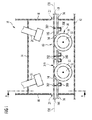
- Fig. 2 is a cross-sectional view of the coating chamber along line A-A shown in Fig. 1 , including a schematic illustration of a part of the backside costing prevention device outside the coating chamber according to embodiments described herein.
- Fig. 3 is a top view on a section of a transport system of the coating chamber shown in Fig. 1 and 2 .
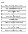
- Fig. 4 is a flow diagram of a coating method according to embodiments described herein.
- Fig. 5 is a flow diagram of another coating method according to embodiments described herein.
- Fig. 6 is a flow diagram of a further coating method according to embodiments described herein.
- Fig. 7 shows a top view on a section of a transport system of another coating chamber according to embodiments described herein.
- Fig. 8 is a top view on a section of a transport system of another coating chamber according to embodiments described herein.
- Fig. 9 shows a top view on a section of a transport system of another coating chamber according to embodiments described herein.
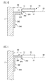
- Fig. 10 illustrates a part of another variation of a backside coating prevention device according to embodiments described herein.
- Fig. 11 shows a part of a further variation of a backside coating prevention device according to embodiments described herein.
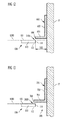
- Fig. 12 shows a part of a yet further variation of a backside coating prevention device according to embodiments described herein.
- Fig. 13 shows a part of another variation of a backside coating prevention device according to embodiments described herein.
- Fig. 14 shows a part of a further variation of a backside coating prevention device according to embodiments described herein.
- Fig. 15 shows a part of a yet further variation of a backside coating prevention device according to embodiments described herein.
- Fig. 16 shows a part of a yet further variation of a backside coating prevention device according to embodiments described herein.
- Fig. 17 shows a part of another variation of a backside coating prevention device according to embodiments described herein.
- applications of the backside coating prevention device, of the coating chamber and of the coating method of the invention are in vacuum sputtering compartments of installations for coating continuously or discontinuously conveyed plate-shaped substrates with thin films.
- the invention is especially useful for coating plate-shaped glass substrates with thin metal films, for example with Ag films, in the manufacture of solar cells.
- the following is directed to a backside coating prevention device in a vacuum sputtering coating chamber for thin-film Ag coating of continuously transported rectangular plate-shaped glass substrates.
- Embodiments of the present invention can also be applied to other coating methods, such as thin-film vapour deposition, and other coating materials than Ag, e.g. other metals or alloys.
- other substrates such as a web or plastic films, having modified shapes may be employed.
- the substrate(s) may be delivered to the coating chamber continuously or may be provided in the coating chamber in a discontinuous mode.
- the coating chamber may not be limited to a vacuum chamber.
- the glass substrate have a thickness in the range between 2 mm and 19 mm.
- the glass substrates have a thickness of 2 mm to 5 mm.
- the size of the glass substrates may be up to 3 meters by 6 meters in some applications.
- Fig. 1 illustrates a cross-sectional view of a coating chamber 10 designed as a vacuum sputtering chamber for thin-film coating of continuously transported rectangular plate-shaped glass substrates 100.
- the coating chamber 10 includes a backside coating prevention device 200, 202, according to embodiments described herein.
- Fig. 2 shows a cross-sectional view of the coating chamber 10 according to Fig. 1 , along line A-A.
- the coating chamber 10 comprises a bottom wall 12, a top wall 14, a front wall 16, a rear wall 18 and two sidewalls 17.
- the material of all walls is stainless steel and the coating chamber 10 is vacuum-tight.
- the front wall 16 includes a substrate feeding opening 20 and the rear wall 18 includes a substrate discharge opening 22.
- the substrate feeding and discharge openings 20, 22 are designed as vacuum locks or airlocks, typically as slit valves, for maintaining a vacuum in the coating chamber 10 when feeding and discharging the glass substrates 100.
- the coating chamber 10 further has process gas inlets (not shown) and is connected to vacuum pumps (not shown) for establishing a vacuum of about 10 -6 Torr.
- the pressure value of 10 -6 Torr should, of course, be understood as an example while other pressure values or ranges are also applicable.
- a typical pressure range for sputtering is between 10 -3 hPa to 10 -2 hPa
- a typical pressure range for evaporation is from lower than 10 -6 hPa to 10 -3 hPa, more typically in the range from 10 -5 hPa to 10 -4 hPa.
- at the top wall 14 one or more, typically two, sputtering cathodes 26 each comprising a target of Ag are provided as coating material source adapted for dispensing coating material into the coating chamber.
- a transport system 30 for continuously conveying a plurality of glass substrates 100 is mounted, as is shown in Fig. 1 and 2 , especially in Fig. 2 .
- the transport system 30 has a front side 31 facing the sputtering cathode 26 and is adapted for supporting on the front side 31 one or more plate-shaped glass substrates 100.
- the transport system 30 comprises a plurality of, typically two, rotatable rolls 32 arranged in parallel to each other throughout the coating chamber 10 successively from the front wall 16 to the rear wall 18. The rolls 32 extend from one sidewall 17 to the opposite sidewall 17.
- each roll 32 is positioned below a cover panel 36 of the transport system 30 and comprises a plurality of spaced apart rings 33 being each concentrically attached to the roll 32.
- the rings 33 extend through openings 34 in the cover panel 36 of the transport system 30 and support the glass substrates 100 and, thereby, define a substrate support plane 120 above the cover panel 36.
- the substrate support plane 120 is shown in Fig. 1 and 2 as a dashed line. Front sides 105 of the glass substrates 100 supported on the rings 33 face the sputtering cathodes 26.
- the cover panel 36 is disposed at a front side 31 of the transport system and has an installation height such that it is positioned typically about 2 mm to about 10 mm, more typically about 2 mm to about 5 mm, most typically at least about 2 mm beneath the substrate support plane 120.
- the resulting distance of at least about 2 mm between the cover panel 36 and the substrate support plane 120 or transported glass substrates 100, respectively, allows for vibrations or sagging of the glass substrates 100 during transport. At the same time contact or collisions of the glass substrates 100 with the cover panel 36 are avoided.
- the distance between cover panel 36 and substrate support plane 120 defines a space below the substrate support plane.
- the rolls 32 are connected to a driving unit 40, which is connected to a control unit 50, the latter being herein also referred to as control means. Both units 40 and 50 are provided outside the coating chamber as shown schematically in Fig. 2 .
- the transport system 30 is made for conveying the plate-shaped glass substrates 100 in a transport direction along a transport path 60.
- the transport path 60 is defined by the transported glass substrates 100 and is positioned on the substrate support plane 120 below the sputtering cathodes 26 and through the substrate feeding and discharge openings 20, 22 of the coating chamber 10. During coating operation, the transport direction extends from the substrate feeding opening 20 to the substrate discharge opening 22.
- each glass substrate 100 has one front side 105 to be coated and facing the sputtering cathodes 26 during transport of the glass substrate on the transport system 30.
- Each glass substrate 100 further includes a backside 110 opposite to the front side 105 and facing the transport system 30 during transport of the glass substrate thereon, and two lateral ends 112 each comprising a lateral side 114.
- gaps 210 are formed between successively transported rectangular plate-shaped glass substrates 100 on the transport system 30. The gaps 210 extend across the full width of the transport path 60.
- an efficient way of operating the sputtering cathodes is a continuous mode.
- Ag particles which are sputtered in the present coating chamber 10 by the sputtering cathodes 26 towards the glass substrates 100, move along a straight trajectory and may also be deflected by collisions with other particles or with the walls of the coating chamber 10.
- a number of the Ag coating material particles which travel to the front sides 105 of the glass substrates 100 may pass the gaps 210 between successively transported rectangular plate-shaped glass substrates 100 and may undesirably be deposited on the backsides 110 of the glass substrates 100.
- additional lateral gaps 500 are formed between the lateral sides 114 of successively transported rectangular plate-shaped glass substrates 100 and the sidewalls 17 of the coating chamber 10, as shown in Fig. 2 . Therefore, the sputtered Ag particles may also pass the lateral gaps 500 and may be deposited on the backsides 110 of the glass substrates 100.
- the backside coating prevention device comprising a barrier gas supply unit.
- the barrier gas supply unit includes a plurality of barrier gas conduits 200, a plurality of barrier gas outlets 202 and a barrier gas source 204.
- the barrier gas may be an inert gas, for example Ar gas of a suitable purity grade which is typically chosen to be the same purity grade as that of the sputter gasses used in the process.
- the barrier gas is not necessarily inert as also gas mixtures containing reactive gasses may be used.
- barrier gasses include inert gasses and/or gasses having high molecular weight.
- the barrier gas conduits 200 are attached to the backside of the cover panel 36 and extend in parallel to the rolls 32 of the transport system 30. Each roll 32 in the example shown in Fig. 1 to 3 is positioned between two barrier gas conduits 200.
- Each barrier gas conduit 200 is connected via a valve 206, typically a control valve, more typically a pressure control valve, to the barrier gas source 204.
- a mass flow controller may be used as an alternative to valve 206 or in combination with valve 206.
- a main MFC may be provided together with additional valves or MFCs at the individual inlets.
- the valve 206 also referred to as a barrier gas valve, and the barrier gas source 204 are provided outside the coating chamber 10.
- one common valve 206 may be provided for all barrier gas conduits 200.
- each barrier gas conduit 200 may have one separate valve 206.
- the valve(s) 206 are typically operated electromagnetically and are controlled by control unit 50.
- each barrier gas conduit 200 is connected to one of the barrier gas outlets 202.
- the barrier gas outlets 202 are provided in the cover panel 36 in parallel to the rolls 32 and transverse, typically perpendicular, to the transport path 60, i.e. transverse, typically perpendicular, to the transport direction during coating operation.
- the barrier gas outlets 202 are longitudinal slits formed in the cover panel 36.
- the barrier gas outlets 202 are arranged in parallel to each other and extend across the full width of the cover panel 36.
- the barrier gas outlets 202 are typically about 2 to about 10 mm, more typically about 2 to about 5 mm, most typically at least about 2 mm spaced apart from the substrate support plane 120, i.e. from the backsides 110 of the transported glass substrates 100.
- a plurality of rectangular plate shaped glass substrates 100 are conveyed one after another through the coating chamber 10, while the sputtering cathodes 26 are operated continuously.
- Each glass substrate 100 is fed into the coating chamber 10 through the substrate feeding opening 20 and arranged on the rings 33 of the transport system 30.
- each glass substrate 100 is continuously transported by the transport system 30 along the transport path 60 below the operating sputtering cathodes 26.
- each glass substrate 100 is discharged through the substrate discharge opening 22. Since a plurality of glass substrates 100 is to be coated and in order to improve the effectiveness of the coating processing, two or more glass substrates 100 may simultaneously be transported on the transport system 30 in the coating chamber 10 one after another. Therefore, each time two rectangular plate shaped glass substrates 100 are successively transported through the coating chamber 10, one of the gaps 210 is formed between the two glass substrates 100. This gap 210 is moving along the transport path 60 during transport of the glass substrates 100.
- a gas barrier is provided at the front side of the transport system and adjacent to the backsides of the plate-shaped substrates for preventing backside coating of the plate-shaped substrate. More typically, a gas barrier may be provided between the front side of the transport system and the plate-shaped substrates for preventing backside coating of the plate-shaped substrates.
- an Ar gas barrier is established in the coating chamber 10 beneath the glass substrates 100, i.e. in the space defined between the cover panel 36 and the backsides 110 of the glass substrates 100, and also in the gaps 210, which are formed between successively transported rectangular plate-shaped glass substrates 100.
- Particles of Ag coating material are ejected from the sputtering cathodes 26 towards the glass substrates 100 and also towards the gaps 210 between successive glass substrates 100. Because of the Ar gas barrier, passage of Ag particles through the gaps 210 between successively transported glass substrates 100 towards the backsides 110 of the glass substrates 100 is reduced or substantially inhibited. Furthermore, the Ar gas barrier also extends through the lateral gaps 500 formed between the lateral ends 114 of the glass substrates 100 and the sidewalls 17 of the coating chamber 10. Therefore, also Ag particles traveling to the lateral gaps 500 between the glass substrates 100 and the sidewalls 17 are prevented to pass these lateral gaps 500 and to deposit on the backsides 110 of the glass substrates 100.
- the Ar gas barrier established by the backside coating prevention device at least reduces or even prevents that Ag target material sputtered towards the glass substrates 100 enters the region below the glass substrates 100 via the gaps formed around the glass substrates 100.
- control unit 50 switches on a constant Ar barrier gas flow.
- This barrier gas flow is established from the barrier gas source 204 through the barrier gas conduits 200 to the barrier gas outlets 202 by opening the corresponding barrier gas valves 206.
- the gas flow rate depends on the type of substrate to be processed, the type, size, and/or geometry of coating chamber 10, as well as on the size of gap 210. Exemplary flow rates are from about 20 sccm up to about 500 sccm.
- the barrier gas flow is adjusted so that the maximum amount of barrier gas in the chamber will be of the same order of magnitude as the process gas.
- the sputtering cathodes 26 are then switched on or, alternatively, are already working.
- the first glass substrate 100 is continuously transported below the operating sputtering cathodes 26 and through the coating chamber 10 while being coated on its front side 105 with Ag particles and supplied on its backside 110 with Ar barrier gas.
- the front end of a second (nth) glass substrate 100 is fed into the coating chamber 10 through the substrate feeding opening 20.
- the second glass substrate 100 is arranged on the rings 33 of the transport system 30 and transported thereon.
- the barrier gas flow through the barrier gas outlets 202 is kept constant as before.
- the second glass substrate 100 is continuously transported below the operating sputtering cathodes 26 and through the coating chamber 10 while being coated on its front side 105 with Ag particles and supplied on its backside 110 with Ar barrier gas.
- the front end and the rear end of the continuously transported first glass substrate 100 consecutively arrive at and are discharged through the discharge opening 22.
- the first and the second periods of time depend on the length, i.e. the distance between the front and the rear ends, of the first glass substrate 100, as the skilled person is aware.
- the front end of the second glass substrate 100 arrives at the substrate discharge opening 22 and is discharged from the coating chamber 10.
- its rear end is discharged through the substrate discharge opening 22, thus completing the process of coating the second glass substrate 100.
- the method steps illustrated above for the second glass substrate 100 may be repeated with a third (n+1) and other successively transported glass substrate(s) 100, while the backsides 110 thereof are supplied with an Ar barrier gas flow, in order to coat a plurality of glass substrates 100 with thin Ag films and simultaneously reduce or prevent coating on the backsides 110 thereof.
- a constant Ar barrier gas flow is continuously supplied through the barrier gas outlets 202 after the first glass substrate 100 has entered the coating chamber 10 until the last glass substrate 100 has been discharged from the coating chamber 10.
- the control unit 50 controls the Ar barrier gas flow by opening and closing the barrier gas valves 206.
- the control unit 50 switches the Ar barrier gas flow on at the time the front end of the first glass substrate 100 is fed into the coating chamber and switches it off at the time the rear end of the last glass substrate 100 is discharged from the coating chamber. Both switching times can be calculated by the control unit 50 based on predetermined information about the length of the glass substrates 100, about the width of the gaps 210 between successively transported glass substrates 100 and based on the transport speed which is controlled by the control unit 50.
- the switching times may be determined based on information derived from sensors connected to the control unit 50, typically movement sensors. Such sensors may, for instance, be positioned outside the coating chamber 10 at the front and rear walls 16, 18 near the substrate feeding opening 20 and substrate discharge opening 22.
- sensors connected to the control unit 50 typically movement sensors.
- Such sensors may, for instance, be positioned outside the coating chamber 10 at the front and rear walls 16, 18 near the substrate feeding opening 20 and substrate discharge opening 22.
- one common barrier gas valve 206 connected to all barrier gas conduits 200 may be used.
- the Ar barrier gas flow may be controlled during transport. This controlling of the Ar gas flow results in a variable or even discontinuous supply of the Ar barrier gas to one or more barrier gas outlets 202.
- a separate barrier gas valve 206 is provided for each barrier gas conduit 200 . This means each barrier gas outlet 202 is connected via one of the barrier gas conduits 200 to the corresponding barrier gas valve 206, which is connected to the barrier gas source 204.
- the control unit 50 transmits a switching command to the barrier gas valve 206 connected to the respective barrier gas outlet 202, in order to reduce or stop the barrier gas flow. After the gap 210 has passed the barrier gas outlet 202, barrier gas flow through this barrier gas outlet is resumed by a command of the control unit 50 to the corresponding barrier gas valve 206.
- Information about the length of the glass substrates 100 and the width of the gaps 210 between successively transported glass substrates 100 may be fed into the control unit 50 before starting the coating process shown in Fig. 5 .
- Such information may be determined during transport by corresponding sensors connected to the control unit 50.
- the latter also controls the driving unit 40 of the transport system 30 and, hence, the transport speed of the glass substrates 100. Therefore, the control unit 50 is able to determine the moving position of each gap 210 between successive glass substrates 100, and the barrier gas valves 206 are accordingly controlled.
- the amount of Ar barrier gas required for backside coating prevention during coating may be reduced, since the barrier gas flow from a barrier gas outlet 202 directly through the gaps 210 between successively transported glass substrates 100 is reduced or avoided.
- the barrier gas flow through the other barrier gas outlets 202 is maintained as long as they are positioned below the transported glass substrates 100. Therefore, an Ar gas barrier below the glass substrates 100 is established and maintained, the gas barrier having a gas pressure and a gas flow into the gaps 210, which are sufficient to safely avoid backside coating.
- One example of typical embodiments described herein is directed to a coating method for glass substrates 100 which are shorter than the distance of the front wall 16 and the rear wall 18 of the coating chamber 10. This means that one or more gaps 210 between successively transported glass substrates 100 are arranged inside the coating chamber 10 during transport. For this case, the coating method explained above and illustrated in Fig. 5 is utilized. Again, backside coating of the glass substrates 100 is avoided while the amount of barrier gas required for backside prevention is reduced.
- the glass substrates 100 are equally long or longer than the distance between the front wall 16 and the rear wall 18. Therefore, during a certain time period of transport through the coating chamber 10, each glass substrate 100 spans the distance between the front wall 16 and the rear wall 18 of the coating chamber 10, i.e. between the substrate feeding and discharge openings 20 and 22. As a result, during this time period, no gap 210 between successive glass substrates 100 is inside the coating chamber 10. Therefore, the barrier gas flow to all barrier gas outlets 202 is reduced or switched off by control unit 50 controlling the barrier gas valves 206.
- the time period during which no gap 210 is arranged inside the coating chamber may be determined as explained above, i.e. based on the information of the length of the glass substrates 100, of the width of the gaps 210 between successive glass substrates 100 and of the transport speed, or based on data from corresponding sensors.
- barrier gas flow through all barrier gas outlets 202 is started and an Ar gas barrier is established beneath the glass substrates 100.
- barrier gas may be supplied consecutively only to such barrier gas outlets 202 which are next to and/or below the moving gap 210.
- only such barrier gas outlets 202 are provided with barrier gas, which are positioned before and after one of the gaps 210 moving through the coating chamber 10 and which at the same time are positioned below the successive glass substrates 100 forming this gap 210.
- a combination of at least parts of the methods shown in Fig. 4 or 5 and Fig. 6 may be utilized. That means, as long as no gap 210 between successively transported glass substrates 100 is arranged in the coating chamber, the Ar barrier gas flow may be reduced or switched off. As soon as one of the gaps 210 enters the coating chamber during transport of the glass substrates 100, one of the barrier gas step sequences shown in Fig. 4 and 5 is started. In each of these cases, backside coating of the glass substrates is avoided while the required amount of barrier gas is kept as small as possible.
- a further variation of embodiments of the backside coating prevention device described herein comprising a specific design of the barrier gas outlets provided in the cover panel 36 of the transport system 30.
- a plurality of barrier gas outlets 302 formed as longitudinal apertures are provided in line.
- each ring 33 extending through an opening 34 of the cover panel 36 is positioned between two parallel longitudinal apertures 302.
- the barrier gas flow will be adjusted to the specific design of the barrier gas outlets 302.
- Other suitable modifications of the embodiments of the backside coating prevention device as described herein are possible, e.g. a combination of the designs of the barrier gas outlets shown in Fig. 3 and 7 , as the skilled person will be aware of.
- Fig. 8 and 9 illustrate other examples of typical embodiments of the backside coating prevention device.
- Fig. 8 shows barrier gas outlets 402 being shorter than the barrier gas outlets 202 indicated in Fig. 3 , such that they do not extend across the full width of the cover panel 36.
- an additional barrier gas outlet 404 is provided in the lateral end portion of the cover panel 36, as shown in Fig. 8 , in parallel to the sidewall 17, i.e. perpendicular to the barrier gas outlets 402.
- the opposite lateral end portion (not shown) of cover panel 36 is also provided with such an additional barrier gas outlet 404 in a mirror-inverted design.
- the barrier gas outlets 404 are connected to additional barrier gas conduits (not shown).
- the barrier gas conduits of the barrier gas outlets 404 may also be connected to the common valve 206. Supplying barrier gas through the resulting system of barrier gas outlets 404 allows for establishing a strong Ar gas barrier in lateral gaps 500 between the transported glass substrates 100 and the sidewalls 17, thus promoting the backside coating preventing effect.
- the additional barrier gas outlets 404 may be connected to the barrier gas source 204 by additional barrier gas conduits connected to one or more additional barrier gas valves (not shown) which are separately controlled by the control unit 50.
- the latter example is especially suitable for a variation of the coating method including at least a part of the step sequence as illustrated in Fig. 6 , i.e. in case that some or all of the glass substrates 100 are equally long or longer than the distance of the front wall 16 and the rear wall 18.
- This example allows for a separate supply of barrier gas to the barrier gas outlets 404 during the time period when one of the glass substrates spans the distance between the front and the rear walls 16 and 18 of the coating chamber 10 and the barrier gas flow through the barrier gas outlets 402 is reduced or stopped. Thereby, a backside coating prevention mainly with respect to the lateral gaps 500 between the glass substrates 100 and the sidewalls 17 is effected.
- Fig. 9 shows a modified design of the example shown in Fig. 8 , the modification being due to the fact that the barrier gas outlets 402 and 404 illustrated in Fig. 8 are split into a plurality of shorter longitudinal apertures.
- the backside prevention effect of the design according to Fig. 9 corresponds to the one of the example shown in Fig. 8 .
- the coating chamber 10 will be designed for glass substrates of specific dimensions. Therefore, the dimensions of the backside coating prevention devices and the features of the corresponding coating method, e.g. the amount of the barrier gas flow, can be specifically adjusted to those dimensions of the glass substrates.
- the skilled person can determine the correct dimensions of the backside coating devices and the correct features of the corresponding coating method such that a suitable gas barrier for prevention of backside coating is achieved.
- the barrier gas outlets may be provided in alignment with the sputtering cathodes 26. That means that some or all of the barrier gas outlets described above, typically the barrier gas outlets 202, 302, 402, 502, 504, are provided only in one or more coating regions 70 below the sputtering cathodes 26, resulting in a reduced amount of barrier gas required for backside coating prevention.
- the barrier gas conduits and barrier gas outlets may be incorporated in a cooling arrangement for cooling the glass substrates 100, thus saving space inside the coating chamber.
- the backside coating prevention device further comprises at least two screens provided at two opposite sidewalls of the coating chamber, the sidewalls extending from the front wall to the rear wall of the coating chamber, each of the two sidewalls being provided with at least one of the screens, each screen having a protruding member protruding from the respective sidewall, each screen having the protruding member positioned so that each protruding member extends along the respective sidewall in parallel to the transport path and is spaced in the range from 1.5 mm to 5 mm from the plate-shaped substrates during coating.
- each glass substrate 100 has the front side 105 to be coated and facing the sputtering cathodes 26 during transport of the glass substrate on the transport system 30. Moreover, each glass substrate 100 has the backside 110 opposite to the front side 105 and facing the transport system 30 during transport of the glass substrate thereon, and two lateral ends 112 each comprising one lateral side 114. It is noted that Fig. 10 only shows one of the two lateral ends 112 of glass substrate 100. It will be understood by those skilled in the art, that the arrangement shown in Fig. 10 is also provided on the opposite lateral side 114 of the glass substrate 100 but in a mirrored configuration.
- two lateral gaps 500 will be formed between the lateral sides 114 of the rectangular plate-shaped glass substrates 100 arranged on the transport system 30 and the sidewalls 17 of the compartment.
- the lateral gaps 500 extend along the sidewalls 17 of the coating chamber 10 in parallel to the transport direction. A number of ejected atoms of the target material may pass these lateral gaps 500 and may undesirably be deposited on the backsides 110 of the glass substrates 100.
- the backside coating prevention device may optionally include two or more screens, the screens being provided at at least two of the walls of the coating chamber 10, the screens being optionally provided below the substrate support plane.
- Each screen has a protruding member protruding from the respective wall.
- two lateral screens 2000 may optionally be included, each sidewall 17 of the coating chamber 10 being provided with one of the screens 2000 below the substrate support plane 120.
- Fig. 10 illustrates an enlarged cross-sectional view of one of the screens 2000 shown in Fig. 2 .
- Each lateral screen 2000 is made of stainless steel and typically has an L-shaped cross section, i.e. it comprises two branches 2002 and 2004 arranged perpendicularly to each other.
- Branch 2002 is attached to the interior side of the sidewall 17 of the coating chamber 10.
- Branch 2004 is provided at the top end of branch 2002 and protrudes towards the centre of the coating chamber in parallel to the substrate support plane 120, i.e. perpendicularly to the sidewall 17. Therefore, branch 2004 forms the protruding member and extends along sidewall 17 in parallel to the transport path 60.
- branch 2004 is positioned about 2 to about 10 mm, typically about 2 to about 5 mm, most typically at least about 2 mm beneath the substrate support plane 120.
- Both branches 2002 and 2004 of the lateral screens 2000 further extend in parallel to the substrate support plane 120 along the sidewall 17 throughout the coating chamber 10, typically at least throughout a sputtering region of the coating chamber 10. That means that the sputtering cathode 26 forming the coating material source is adapted to dispense coating material at least into the coating region 70 of the coating chamber 10 and each screen 2000 is provided at least in the coating region 70.
- the protruding branch 2004 is positioned to be at least 2 mm spaced apart from the one or more plate-shaped substrates 100 during coating. Furthermore, branch 2004 protrudes from the sidewall 17 such that the substrate support plane 120 is positioned between the sputtering cathode 26 and branch 2004. More specifically, as mentioned above, each glass substrate 100 supported on the substrate support plane 120 has the backside 110 and two lateral ends 112 each comprising one lateral side 114. As shown in Fig.
- gap 2010 is formed between the backside 110 of the glass substrate 100 and the branch 2004, branch 2004 being about 2 to about 10 mm, typically about 2 to about 5 mm, most typically at least about 2 mm spaced apart from the backside 110 of the glass substrate 100, depending on the installation height of branch 2002 as explained above. Therefore, gap 2010 has a width of about 1.5 mm to about 10 mm, typically about 1.5 mm to about 5 mm, most typically at least about 2 mm. As a result of this small width, most of the Ag particles sputtered towards the lateral ends 112 of the glass substrate 100 are prevented from passing to the backside 110 thereof, since they are deposited on the upper surfaces of branches 2004 and the lateral sides 114 of the glass substrate.
- the gap 2010 between protruding branch 2004 and the glass substrate 100 also allows for vibrations or sagging of the glass substrate 100 during transport, preventing contact or collisions of the glass substrate 100 with the protruding branches 2004 of the backside coating prevention device.
- glass substrates 100 are successively fed into the coating chamber 10 through the substrate feeding opening 20, continuously conveyed by the transport system 30 along the transport path 60 on the substrate support plane 120 below the operating sputtering cathode 26, and discharged through the substrate discharge opening 22.
- Particles of Ag coating material are ejected from the sputtering cathode 26 towards the glass substrates 100 and also laterally towards the lateral gaps 500 which are formed between the rectangular plate-shaped glass substrates 100 and the sidewalls 17 of the coating chamber 10. Coating particles ejected laterally towards these lateral gaps 500 are mainly deposited on the upper surfaces of the protruding branches 2004 of the screens 2000.
- the backside coating prevention device may include screens each comprising a protruding member having a lateral end which protrudes into the coating chamber and is positioned on the substrate support plane 120.
- screens each comprising a protruding member having a lateral end which protrudes into the coating chamber and is positioned on the substrate support plane 120.
- FIG. 11 An example of this variation of embodiments is shown in Fig. 11 . Like in Fig. 10 , a cross-sectional view of only one screen 3000 of such a backside coating prevention device is illustrated in Fig. 11 . However, typically two lateral screens 3000 are included in this example of the backside coating prevention device.
- a screen 3000 comprises a branch 3002 attached to the sidewall 17 of the coating chamber 10 and a branch 3004 formed as protruding member.
- Branch 3004 is mounted at the upper end of branch 3002 and protrudes into the coating chamber 10.
- Branch 3004 has a lateral end 3006 facing the lateral side 114 of the glass substrate 100.
- the installation height of branch 3004 is such that the lateral end 3006 is positioned on the substrate support plane 120. Since in this example, screen 3000 is L-shaped, i.e. branches 3002 and 3004 are arranged perpendicularly to each other, the whole branch 3004 is positioned on the substrate support plane 120.
- the length of branch 3004 is such that its lateral end 3006 is at least about 2 mm spaced apart, more specifically about 2 to about 10 mm, typically about 2 to about 5 mm, most typically about 2 mm spaced apart from the lateral side 114 of the glass substrate 100.
- a small gap 3010 of a width of at least about 2 mm is provided between branch 3004 and the lateral side 114 of the glass substrate 100. Through this gap 3010, only a negligible amount of Ag particles ejected from the sputtering cathodes 26 towards the lateral ends 112 of the glass substrate 100 will pass.
- the backside coating prevention device including two screens 3000 according to the example shown in Fig. 11 during coating operation, substantially all Ag coating particles traveling towards the lateral gaps 500 between the glass substrate 100 and the sidewalls 17 are deposited on the upper surfaces of the protruding branches 3004, the lateral ends 3006 thereof and at the lateral sides 114 of the glass substrate 100.
- the screens 3000 on both sidewalls 17 of the coating chamber, passage of Ag particles through the lateral gaps 500 between the glass substrates 100 and the sidewalls 17 towards the backside 110 of the glass substrate 100 is reduced or substantially inhibited.
- the dimensions of the branches, especially of the protruding branches will be adjusted with respect to the width of the glass substrates to be coated.
- the coating chamber 10 will be designed for glass substrates of specific dimensions so that the dimensions, especially the lengths, of the screens of the backside coating prevention devices shown in Fig. 10 and 11 can be specifically adjusted to those dimensions of the glass substrates.
- the skilled person can determine the correct dimension of the screens of the embodiments of Fig. 10 and 11 , so that a specific gap width between the screens and the glass substrates is achieved in the coating chamber during operation.
- each glass substrate 100 has a substrate front side 105 (also referred to herein as front side 105) to be coated and facing the sputtering cathodes 26 during transport of the glass substrate on the transport system 30.
- the front side 105 of each glass substrate 100 defines a substrate front plane 1200.
- the substrate front plane 1200 is shown in Fig. 12 as a dashed line.
- each glass substrate 100 has a backside 110 opposite to the front side 105 and facing the transport system 30 during transport of the glass substrate thereon.
- each glass substrate has two lateral ends 112, each comprising a lateral side 114. It is noted that Fig. 12 only shows one of the two lateral ends 112 of glass substrate 100. It will be understood by those skilled in the art that the arrangement shown in Fig. 12 is provided on the opposite lateral side of glass substrate 100 but in mirrored configuration.
- the sputtering cathode 26 and, hence, the target thereof may extend over the lateral ends 112 of the glass substrate, in order to apply a coating of a uniform thickness, e.g. of a substantially constant thickness, onto the front side 105 of the substrate 100 over the whole area of the front side 105, i.e. even on the lateral ends 112.
- a uniform thickness e.g. of a substantially constant thickness
- two gaps 500 will be formed between the lateral sides 114 of the rectangular plate-shaped glass substrates 100 arranged on the transport system 30 and the sidewalls 17 of the compartment. These gaps 500 extend along the sidewalls 17 of the coating chamber 10 substantially in parallel to the transport direction.
- a number of ejected atoms of the target material may pass these gaps 500 and may undesirably be deposited on the backsides 110 of the glass substrates, typically due to scattering.
- a backside coating prevention device may optionally comprise two or more screens, the screens being provided at at least two of the walls of the coating chamber 10, each screen having a protruding member protruding from the respective wall, the screens being optionally provided above the substrate front plane.
- a backside coating prevention device may include two lateral screens 600, each sidewall 17 of the coating chamber 10 being provided with one of the screens 600 above the substrate front plane 1200.
- Fig. 12 illustrates an enlarged cross-sectional view of one example of the screens 600 of the backside coating prevention device according to embodiments disclosed herein. It is noted that the proportions of the screen 600 and the glass substrate 100 as shown in Fig. 12 are not to scale.
- Each lateral screen 600 is typically made of stainless steel and typically has an L-shaped cross section, i.e. it comprises two branches 602 and 604 arranged substantially perpendicularly to each other.
- Branch 602 is attached to the interior surface of the sidewall 17 of the coating chamber 10.
- Branch 604 is provided at the bottom end of branch 602 and protrudes towards the centre of the coating chamber substantially in parallel to the substrate front plane 1200, i.e. substantially perpendicularly to the sidewall 17.
- branch 604 forms the protruding member and extends along sidewall 17 substantially in parallel to the transport path 60.
- the installation height of branch 602 at the sidewall 17 in the coating chamber 10 is such that branch 604 is positioned about 1.5 to about 10 mm, typically about 1.5 to about 5 mm, most typically about 2 mm above the substrate front plane 1200.
- Both branches 602 and 604 of the lateral screens 600 further extend substantially in parallel to the substrate front plane 1200 along the sidewall 17 throughout the coating chamber 10, typically at least throughout a sputtering region of the coating chamber 10. That means that the sputtering cathode 26 forming the coating material source is adapted to dispense coating material at least into a coating region 70 of the coating chamber 10 and each screen 600 is provided at least in the coating region 70.
- the material(s) of the screens of any example of embodiments disclosed herein is (are) vacuum-compatible and may be at least one element selected from the group consisting of Aluminum, an Aluminum alloy, or stainless steel in any of the embodiments described herein.
- the thickness of the screens or of the protruding member in any embodiment described herein e.g. the thickness of any of the branches 602 and 604 in the present embodiment, may for example be a few mm, typically in the range from about 1 mm to about 10 mm, more typically from about 2 mm to about 5 mm.
- typical dimensions of the protruding member e.g.
- the dimensions of branch 604 in the present embodiment substantially in parallel to the transport direction may be in the range from about 20 cm to about 100 cm.
- the protruding branch 604 is positioned to be about 1.5 mm to about 10 mm spaced apart from the one or more plate-shaped substrates 100 during coating. Furthermore, branch 604 protrudes from the sidewall 17 such that the branch 604 is positioned between the sputtering cathode 26 and the substrate front plane 1200. More specifically, as mentioned above, each glass substrate 100 supported on the substrate support plane has a front side 105 and lateral ends 112 each comprising a lateral side 114. As shown in Fig.
- gap 2100 is formed between the front side 105 of the glass substrate 100 and the lower side of branch 604, branch 604 being about 1.5 to about 10 mm, typically about 1.5 to about 5 mm, most typically about 2 mm spaced apart from the front side 105 of the glass substrate 100, depending on the installation height of branch 602 as explained above. Therefore, gap 2100 has a width of about 1.5 mm to about 10 mm, typically about 1.5 mm to about 5 mm, most typically about 2 mm. As a result of this small width, most of the Ag particles sputtered towards the gaps 500 between the glass substrate 100 and the sidewalls 17 are prevented from passing to the backside 110 thereof, since they are deposited on the upper surface of branches 604.
- the gap 2100 between protruding branch 604 and glass substrate 100 also allows for vibrations or sagging of the glass substrate 100 during transport, preventing contact or collisions of the glass substrate 100 with the protruding branches 604 of the backside coating prevention device.
- the protruding member e.g. formed as branch 604 has a lateral end protruding into the coating chamber, wherein the lateral end is positioned to be spaced apart from but substantially aligned with one of the lateral sides 114 of at least one of the one or more plate-shaped substrates 100 on the substrate support.
- branch 604 has a lateral end formed as a front face 606. The lateral end of branch 604 is positioned above the substrate front plane 1200 and is spaced about 2 mm from the lateral side 114 of glass substrate 100 by gap 2100.
- front face 606 of screen 600 is substantially aligned with the lateral side 114 of the glass substrate 100 supported on the transport system 30. Therefore, contact or collisions of the glass substrate 100 with the protruding branches 604 of the backside coating prevention device are avoided. Furthermore, Ag particles, which are sputtered towards the gaps 500 between the glass substrate 100 and the sidewalls 17, move along a straight trajectory and may also be deflected or scattered by collisions with other particles or with the sidewalls 17.
- glass substrates 100 are successively fed into the coating chamber 10 through the substrate feeding opening, continuously conveyed by the transport system 30 along the transport path 60 on the substrate support plane below the operating sputtering cathode 26, and discharged through the substrate discharge opening. Consequently, since the plate-shaped glass substrates have typically the same thicknesses, the front sides of the glass substrates define a common substrate front plane.
- glass substrates of such varying dimensions or thicknesses may be successively fed into the coating chamber 10 that the protruding member of the backside coating prevention device is positioned to be spaced at least 1.5 mm from the one or more plate-shaped substrates during coating.
- branch 604 is about 1.5 to about 10 mm, typically about 1.5 to about 5 mm, most typically about 2 mm spaced apart from the front side 105 of the glass substrates 100 having varying dimensions and, hence, from the substrate front planes 1200 defined thereby.
- Particles of Ag coating material are ejected from the sputtering cathode 26 towards the glass substrates 100 and also laterally towards the gaps 500 which are formed between the rectangular plate-shaped glass substrates 100 and the sidewalls 17 of the coating chamber 10. Coating particles ejected laterally towards these gaps 500 are mainly deposited on the upper surfaces of the protruding branches 604 of the screens 600.
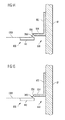
- FIG. 13 a cross-sectional view of only one screen 700 of such a backside coating prevention device is shown.
- typically two lateral screens 700 are included in the backside coating prevention device.
- Each lateral screen 700 includes two branches 702 and 704 which are arranged as described with respect to the embodiment shown in Fig. 12 .
- the backside coating prevention device includes a protruding member having a lateral end being positioned to extend over a lateral part of the front side 105 of at least one of the one or more plate-shaped substrates 100 on the substrate support.
- Branch 704 differs from branch 604 shown in Fig.
- branch 704 extends over the lateral part 112 of the front side 105 of the glass substrate 100 during transport, i.e. it extends partially over the front side of the transport path 60. Thereby, backside coating of glass substrate 100 is prevented, even if an amount of the Ag particles laterally ejected from the sputtering cathode 26 is deflected or scattered by the sidewalls 17 or other particles towards the gap 2100 between the protruding branch 704 and the front side 105 of the glass substrate 100.
- said lateral end of the protruding member of the screen may be formed to taper away from the front side of a plate-shaped substrate 100 on the substrate support.
- Figs. 14 and 15 respectively, examples of such a backside coating prevention device are shown, which correspond to the embodiment shown in Fig. 12 except for the design of the protruding lateral ends of the protruding branches.
- L-shaped screen 800 of Fig. 14 includes a branch 802 attached to the sidewall 17 and a branch 804 protruding above the substrate front plane 1200.
- the lateral end 806 of branch 804 has a wedge-shaped slanted face such that the protruding tip thereof is directed towards the top wall 14 of the coating chamber 10.
- Screen 850 shown in Fig. 15 has two branches 852 and 854.
- Branch 852 is attached to the sidewall 17 while branch 854 protrudes substantially in parallel to the substrate front plane 1200.
- the lateral end 856 of branch 854 has a tapered form such that the protruding central tip thereof is directed towards the opposing sidewall 17 of the coating chamber 10.
- the protruding laterals ends 806 and 856 of the screens 600 and 650 are formed tapering away from the front side of the glass substrate 100, the clearance of the glass substrate 100 during transport is improved.
- a sufficient width of gap 2100 may be provided in the tapered portion of the protruding branches 804, 854 while the bottom surface of these branches 804, 854 is spaced from the substrate front plane 1200 less than the sufficient minimum gap width.
- the backside coating prevention device may have screens each comprising a protruding member being substantially aligned with the substrate. Furthermore, according to embodiments described herein, the backside coating prevention device may have screens each comprising a protruding member being substantially aligned with the substrate front plane 1200. An example of these embodiments is shown in Fig. 16 .
- a screen 1000 comprises a branch 1002 attached to the sidewall 17 of the coating chamber 10 and a branch 1004 formed as a protruding member.
- Branch 1004 is mounted at the bottom end of branch 1002 and protrudes into the coating chamber 10.
- Branch 1004 has a lateral end 1006 facing the lateral side 114 of the glass substrate 100.
- the installation height of branch 1004 may be adjusted so that the upper side of branch 1004 is substantially aligned with the substrate front plane 1200, as shown in Fig. 16 .
- screen 1000 is L-shaped, i.e. branches 1002 and 1004 are arranged substantially perpendicularly to each other.
- the length of branch 1004 is such that its lateral end 1006 is laterally spaced from the lateral side 114 of the glass substrate 100 by about 1.5 to about 10 mm, typically about 1.5 to about 5 mm, and most typically about 2 mm.
- a small lateral gap 1010 having a width of about 1.5 to about 10 mm, typically about 1.5 to about 5 mm, and most typically about 2 mm is provided between branch 1004 and the lateral side 114 of the glass substrate 100. Through this gap 1010, only a negligible amount of Ag particles ejected from the sputtering cathodes 26 will pass.
- the protruding member may be substantially aligned with the substrate front plane.
- the installation height of branch 1004 may be adjusted so that the upper side of branch 1004 is substantially aligned with the substrate front plane 1200, resulting in a first position of the protruding member.
- the installation height of branch 1004 shown in Fig. 16 may be adjusted so that the lower side of branch 1004 is substantially aligned with the substrate front plane 1200, resulting in a second position of the protruding member.
- the protruding member may be installed at any other position substantially aligning the protruding member with the substrate front plane.
- the lateral end of the protruding member may be positioned on the substrate front plane.
- the upper part of the lateral end 1006 of the branch 1004 shown in Fig. 16 is positioned on the substrate front plane 1200.
- other parts of the lateral end 1006 may be positioned on the substrate front plane 1200.
- the protruding member may be positioned such that it is aligned with the substrate.
- the protruding member may have any position in which it is positioned opposite to, e.g. facing, a lateral side of a substrate supported on the substrate support.
- branch 1004 may have any position in which the lateral end 1006 of the branch 1004 may face, at least partially, the lateral side 114 of the substrate 100.
- the screens of the backside coating prevention device may each have a protruding branch arranged in an inclined way with an inclination different from 90 degrees with respect to the sidewall 17. Furthermore, for each screen the branch which is attached to the sidewall 17 may be mounted thereon at such an installation height, and the protruding branch may have such a length, that the lateral end of the protruding branch is positioned at least about 1.5 mm spaced apart from the lateral side 114 of the glass substrate 100.
- the backside coating prevention device may have screens each comprising a protruding member comprising a panel and a holder, the holder being provided at a respective wall.
- the panel may be provided at the holder.
- the panel may be an elongated panel.
- the holder may be an elongated holder or may include a plurality of holder elements.
- the holder may be a protruding integral part of the respective wall.
- the holder may be a member provided at the respective wall.
- a screen 4000 may be an elongated panel 4004 mounted at its lower side at fixture 4010 of an elongated holder 4008 protruding from a sidewall 17.
- the lower side of panel 4004 may be directly attached to the holder 4008, with no fixture or spacing between the lower side of the panel 4004 and the upper side of holder 4008.
- the panel 4004 may extend substantially in parallel to the transport path 60 and, hence, to the substrate front plane 1200.
- the holder 4008 may be an elongated protrusion of the sidewall 17.
- the holder 4008 may be an integral part of the sidewall 17, as shown in Fig. 17 .
- the holder 4008 may be an elongated member attached at the sidewall 17.
- the holder 4008 and the panel 4004 extend along the sidewall 17 in parallel to each other and in parallel to the transport path 60.
- the dimensions of panel 4004 are such that a front side 4006 of the panel 4004 is substantially aligned with the lateral side 114 of the substrate 100.
- the holder 4008 may be provided at an installation height at sidewall 17 such that the lower side of panel 4004 is positioned spaced from and above glass substrate 100 during transport, such that the gap 2100 is formed between the panel 4004 and the substrate 100.
- the gap width of the gap 2100 between the bottom surface of the panel 4004 and the substrate front plane 1200 is in the range of about 1.5 mm to 5 mm, more typically about 2 mm.
- the holder 4008 may be provided at the sidewall 17 in an installation height such that the upper side of the holder 4008 is substantially aligned with the front side 105 of the substrate and, at the same time, the gap 2100 is formed between the panel 4004 and the substrate 100.
- Each above mentioned design of the example shown in Fig. 17 results in a reliable reduction or prevention of a backside coating of glass substrate 100, because of the small width of the gaps 2100 between screen 4000 and the front side of glass substrate 100 in the range from about 1.5 to 5 mm, typically about 2 mm.
- the edges of the protruding members may have a rounded from, in order to avoid sharp edges which might damage the glass substrates 100 in case of vibrations or sagging during transport.
- one or more additional screens having a shape as described above in any of the embodiments and examples, respectively, may be provided at each sidewall 17 above and/or below the substrate front plane 1200, i. e. above and/or below the screens typically substantially in parallel thereto. Thereby, prevention of backside coating of the glass substrates 100 is promoted.
- the substrates 100 may be conveyed vertically instead of horizontally through the coating chamber.
- the screens may be installed at other positions in the coating chamber, e.g. at the top and the bottom wall of the coating chamber, or may have correspondingly adapted modified profiles, in order to allow an installation at the sidewalls.
- the coating chamber 10 may be a tube-shaped vessel having a tube-shaped wall closed by circular front and rear lids.
- the glass substrates 100 are transported in a direction parallel to the longitudinal axis of the tube-shaped vessel.
- the circular front and rear lids of this modification correspond to the front and rear walls as defined above.
- the sidewalls as defined above correspond to the areas of the tube-shaped wall facing the lateral ends 112 of the glass substrates 100 during transport.
- a typical example of a material of the glass substrate 100 is soda lime float glass and may have a standard or reduced iron content.
- a pre-coated glass substrate may be used.
- the glass substrate 100 may be coated with a transparent conductive oxide.
- the glass substrate 100 may have an amorphous and/or microcrystalline silicon p-in structure or an amorphous and/or microcrystalline silicon p-i-n-p-i-n tandem cell structure.
- substrates having a solar cell layer stack may be used in embodiments described herein.
- typical dimensions of glass plates used as glass substrate 100 according to embodiments described herein are in the range of about 1x1 sqm to about 3x6 sqm, typically about 2.2x2.6 sqm or about 1.1x1.3 sqm.
- the thickness of the glass substrate 100 according to embodiments described herein is in the range of about 2 mm to about 5 mm.
Landscapes
- Chemical & Material Sciences (AREA)
- Engineering & Computer Science (AREA)
- Materials Engineering (AREA)
- Chemical Kinetics & Catalysis (AREA)
- Mechanical Engineering (AREA)
- Metallurgy (AREA)
- Organic Chemistry (AREA)
- Plasma & Fusion (AREA)
- Analytical Chemistry (AREA)
- Physics & Mathematics (AREA)
- General Chemical & Material Sciences (AREA)
- Physical Vapour Deposition (AREA)
- Surface Treatment Of Glass (AREA)
- Coating Apparatus (AREA)
Abstract
Description
- The present invention relates to a backside coating prevention device, a coating chamber, and a method of coating. Particularly, the present invention relates to a backside coating prevention device adapted for a coating chamber for coating plate-shaped substrates, a coating chamber for coating plate-shaped substrates, the coating chamber comprising a backside coating prevention device, and a method of coating plate-shaped substrates.
- Thin-film coating of material on plate-shaped substrates may be accomplished in many ways, for example by evaporation or sputtering of the coating material. In some instances, for example in the manufacture of solar cells, it is desirable to coat exclusively one surface or maybe also the lateral faces of the plate-shaped substrates.
- In known installations for coating continuously conveyed plate-shaped substrates, typically glass substrates, with thin layers by cathode sputtering, several compartments are located one after another. Each compartment comprises at least one sputtering cathode and process gas inlets, and is connected with a vacuum pump for evacuation. The compartments are connected to one another by means of openings, typically vacuum locks or airlocks, which may comprise one or more slit valves. A transport system comprising transport rolls for transporting the plate-shaped substrates along a path below the sputtering cathodes and passing the substrates through the openings between the compartments is provided.
- When operating a sputtering cathode, a plasma is established and ions of the plasma are accelerated onto a target of coating material to be deposited onto the substrates. This bombardment of the target results in ejection of atoms of the coating material, which accumulate as a deposited film on the substrate below the sputtering cathode.
- In known designs of a compartment for sputtering continuously transported rectangular plate-shaped substrates, coating material may be deposited not only on the front sides and, in some instances, on the lateral sides of the plate-shaped substrates as desired, but also on the backsides thereof, which is especially undesirable for glass substrates for solar cells.
- In one aspect it is provided a backside coating prevention device adapted for a coating chamber for coating plate-shaped substrates, said coating chamber being adapted for coating continuously or discontinuously transported plate-shaped substrates, including a front wall having a substrate feeding opening and a rear wall having a substrate discharge opening, a coating material source adapted for dispensing coating material into the coating chamber, and a transport system, a front side of the transport system facing the coating material source, the transport system being adapted for continuously or discontinuously transporting a plurality of plate-shaped substrates along a transport path on the front side of the transport system, wherein said backside coating prevention device is adapted for providing a gas barrier at the front side of the transport system and adjacent to the backsides of the plurality of plate-shapes substrates for preventing backside coating of the plate-shaped substrates.
- A further aspect is directed to a coating chamber for coating plate-shaped substrates, said coating chamber being adapted for coating continuously or discontinuously transported plate-shaped substrates, including a front wall having a substrate feeding opening and a rear wall having a substrate discharge opening, a coating material source adapted for dispensing coating material into the coating chamber, and a transport system, a front side of the transport system facing the coating material source, the transport system being adapted for continuously or discontinuously transporting a plurality of plate-shaped substrates along a transport path on the front side of the transport system, wherein said backside coating prevention device is adapted for providing a gas barrier at the front side of the transport system and adjacent to the backsides of the plurality of plate-shapes substrates for preventing backside coating of the plate-shaped substrates.
- According to another aspect, a method of coating plate-shaped substrates in a coating chamber includes conveying a plurality of plate-shaped substrates through the coating chamber by a) feeding one of the plate-shaped substrates into the coating chamber through a substrate feeding opening in a front wall of the coating chamber and arranging the plate-shaped substrate on a transport system for continuously or discontinuously transporting the plurality of plate-shaped substrates along a transport path on the front side of the transport system, b) continuously or discontinuously transporting the plate-shaped substrate along the transport path, while providing a gas barrier at the front side of the transport system and adjacent to the backside of the plate-shaped substrate for preventing backside coating of the plate-shaped substrate and while dispensing coating material from a coating material source provided in the coating chamber towards a front side of the plate-shaped substrate, c) discharging the plate-shaped substrate through a substrate discharge opening in a rear wall of the coating chamber, wherein the plate-shaped substrate is discharged while another one of the plate-shaped substrates is being conveyed through the coating chamber.
- Some of the above mentioned aspects will be described in more detail in the following description of typical embodiments with reference to the following drawings in which:
-
Fig. 1 shows a cross-sectional view of a coating chamber including a backside coating prevention device according to embodiments described herein. -
Fig. 2 is a cross-sectional view of the coating chamber along line A-A shown inFig. 1 , including a schematic illustration of a part of the backside costing prevention device outside the coating chamber according to embodiments described herein. -
Fig. 3 is a top view on a section of a transport system of the coating chamber shown inFig. 1 and2 . -
Fig. 4 is a flow diagram of a coating method according to embodiments described herein. -
Fig. 5 is a flow diagram of another coating method according to embodiments described herein. -
Fig. 6 is a flow diagram of a further coating method according to embodiments described herein. -
Fig. 7 shows a top view on a section of a transport system of another coating chamber according to embodiments described herein. -
Fig. 8 is a top view on a section of a transport system of another coating chamber according to embodiments described herein. -
Fig. 9 shows a top view on a section of a transport system of another coating chamber according to embodiments described herein. -
Fig. 10 illustrates a part of another variation of a backside coating prevention device according to embodiments described herein. -
Fig. 11 shows a part of a further variation of a backside coating prevention device according to embodiments described herein. -
Fig. 12 shows a part of a yet further variation of a backside coating prevention device according to embodiments described herein. -
Fig. 13 shows a part of another variation of a backside coating prevention device according to embodiments described herein. -
Fig. 14 shows a part of a further variation of a backside coating prevention device according to embodiments described herein. -
Fig. 15 shows a part of a yet further variation of a backside coating prevention device according to embodiments described herein. -
Fig. 16 shows a part of a yet further variation of a backside coating prevention device according to embodiments described herein. -
Fig. 17 shows a part of another variation of a backside coating prevention device according to embodiments described herein. - Reference will now be made in detail to the various embodiments, one ore more examples of which are illustrated in the figures. Each example is provided by way of explanation, and is not meant as a limitation of the invention. Within the following description of the drawings, the same reference numbers refer to the same components. Generally, only the differences with respect to the individual embodiments are described.
- Typically, applications of the backside coating prevention device, of the coating chamber and of the coating method of the invention are in vacuum sputtering compartments of installations for coating continuously or discontinuously conveyed plate-shaped substrates with thin films. The invention is especially useful for coating plate-shaped glass substrates with thin metal films, for example with Ag films, in the manufacture of solar cells.
- Without limiting the scope of the invention, the following is directed to a backside coating prevention device in a vacuum sputtering coating chamber for thin-film Ag coating of continuously transported rectangular plate-shaped glass substrates. Embodiments of the present invention can also be applied to other coating methods, such as thin-film vapour deposition, and other coating materials than Ag, e.g. other metals or alloys. Furthermore, other substrates, such as a web or plastic films, having modified shapes may be employed. Moreover, the substrate(s) may be delivered to the coating chamber continuously or may be provided in the coating chamber in a discontinuous mode. Additionally, the coating chamber may not be limited to a vacuum chamber. Typically, the glass substrate have a thickness in the range between 2 mm and 19 mm. For example, in typical solar cell applications the glass substrates have a thickness of 2 mm to 5 mm. Furthermore, the size of the glass substrates may be up to 3 meters by 6 meters in some applications.
-
Fig. 1 illustrates a cross-sectional view of acoating chamber 10 designed as a vacuum sputtering chamber for thin-film coating of continuously transported rectangular plate-shaped glass substrates 100. Thecoating chamber 10 includes a backsidecoating prevention device Fig. 2 shows a cross-sectional view of thecoating chamber 10 according toFig. 1 , along line A-A. Thecoating chamber 10 comprises abottom wall 12, atop wall 14, afront wall 16, arear wall 18 and twosidewalls 17. The material of all walls is stainless steel and thecoating chamber 10 is vacuum-tight. Thefront wall 16 includes a substrate feeding opening 20 and therear wall 18 includes asubstrate discharge opening 22. The substrate feeding anddischarge openings coating chamber 10 when feeding and discharging theglass substrates 100. Thecoating chamber 10 further has process gas inlets (not shown) and is connected to vacuum pumps (not shown) for establishing a vacuum of about 10-6 Torr. The pressure value of 10-6 Torr should, of course, be understood as an example while other pressure values or ranges are also applicable. For example, a typical pressure range for sputtering is between 10-3 hPa to 10-2 hPa, a typical pressure range for evaporation is from lower than 10-6 hPa to 10-3 hPa, more typically in the range from 10-5 hPa to 10-4 hPa. Furthermore, at thetop wall 14 one or more, typically two, sputteringcathodes 26 each comprising a target of Ag are provided as coating material source adapted for dispensing coating material into the coating chamber. - On the
bottom wall 12, as a substrate support, atransport system 30 for continuously conveying a plurality ofglass substrates 100 is mounted, as is shown inFig. 1 and2 , especially inFig. 2 . Thetransport system 30 has afront side 31 facing thesputtering cathode 26 and is adapted for supporting on thefront side 31 one or more plate-shaped glass substrates 100. Thetransport system 30 comprises a plurality of, typically two,rotatable rolls 32 arranged in parallel to each other throughout thecoating chamber 10 successively from thefront wall 16 to therear wall 18. Therolls 32 extend from onesidewall 17 to theopposite sidewall 17. Furthermore, eachroll 32 is positioned below acover panel 36 of thetransport system 30 and comprises a plurality of spaced apart rings 33 being each concentrically attached to theroll 32. Therings 33 extend throughopenings 34 in thecover panel 36 of thetransport system 30 and support theglass substrates 100 and, thereby, define asubstrate support plane 120 above thecover panel 36. Thesubstrate support plane 120 is shown inFig. 1 and2 as a dashed line.Front sides 105 of theglass substrates 100 supported on therings 33 face the sputteringcathodes 26. Thecover panel 36 is disposed at afront side 31 of the transport system and has an installation height such that it is positioned typically about 2 mm to about 10 mm, more typically about 2 mm to about 5 mm, most typically at least about 2 mm beneath thesubstrate support plane 120. The resulting distance of at least about 2 mm between thecover panel 36 and thesubstrate support plane 120 or transportedglass substrates 100, respectively, allows for vibrations or sagging of theglass substrates 100 during transport. At the same time contact or collisions of theglass substrates 100 with thecover panel 36 are avoided. Furthermore, the distance betweencover panel 36 andsubstrate support plane 120 defines a space below the substrate support plane. - The
rolls 32 are connected to a drivingunit 40, which is connected to acontrol unit 50, the latter being herein also referred to as control means. Bothunits Fig. 2 . Thetransport system 30 is made for conveying the plate-shapedglass substrates 100 in a transport direction along a transport path 60. The transport path 60 is defined by the transportedglass substrates 100 and is positioned on thesubstrate support plane 120 below the sputteringcathodes 26 and through the substrate feeding anddischarge openings coating chamber 10. During coating operation, the transport direction extends from thesubstrate feeding opening 20 to thesubstrate discharge opening 22. - As shown in e.g.
Fig. 2 , eachglass substrate 100 has onefront side 105 to be coated and facing the sputteringcathodes 26 during transport of the glass substrate on thetransport system 30. Eachglass substrate 100 further includes abackside 110 opposite to thefront side 105 and facing thetransport system 30 during transport of the glass substrate thereon, and two lateral ends 112 each comprising alateral side 114. During transport of theglass substrates 100, as illustrated inFig. 1 ,gaps 210 are formed between successively transported rectangular plate-shapedglass substrates 100 on thetransport system 30. Thegaps 210 extend across the full width of the transport path 60. Typically, when coating a plurality of successively transported substrates, an efficient way of operating the sputtering cathodes is a continuous mode. Ag particles, which are sputtered in thepresent coating chamber 10 by the sputteringcathodes 26 towards theglass substrates 100, move along a straight trajectory and may also be deflected by collisions with other particles or with the walls of thecoating chamber 10. A number of the Ag coating material particles which travel to thefront sides 105 of theglass substrates 100 may pass thegaps 210 between successively transported rectangular plate-shapedglass substrates 100 and may undesirably be deposited on thebacksides 110 of theglass substrates 100. Moreover, additionallateral gaps 500 are formed between thelateral sides 114 of successively transported rectangular plate-shapedglass substrates 100 and thesidewalls 17 of thecoating chamber 10, as shown inFig. 2 . Therefore, the sputtered Ag particles may also pass thelateral gaps 500 and may be deposited on thebacksides 110 of theglass substrates 100. - Therefore, as is illustrated in
Fig. 1 to 3 , in the coating chamber 10 a backside coating prevention device is provided, the backside coating prevention device according to embodiments described herein comprising a barrier gas supply unit. In a typical example shown inFig. 1 to 3 , the barrier gas supply unit includes a plurality ofbarrier gas conduits 200, a plurality ofbarrier gas outlets 202 and abarrier gas source 204. The barrier gas may be an inert gas, for example Ar gas of a suitable purity grade which is typically chosen to be the same purity grade as that of the sputter gasses used in the process. However, the barrier gas is not necessarily inert as also gas mixtures containing reactive gasses may be used. For example, a mixture of Ar, N2, and O2 may be used in a reactive process. Such mixture is not inert due to the O2. In general, any gas not having a negative influence on the process may qualify as a barrier gas to be used in the disclosed apparatus and process. Typical but non-limiting examples of barrier gasses include inert gasses and/or gasses having high molecular weight. Thebarrier gas conduits 200 are attached to the backside of thecover panel 36 and extend in parallel to therolls 32 of thetransport system 30. Eachroll 32 in the example shown inFig. 1 to 3 is positioned between twobarrier gas conduits 200. Eachbarrier gas conduit 200 is connected via avalve 206, typically a control valve, more typically a pressure control valve, to thebarrier gas source 204. It will be understood by those skilled in the art that a mass flow controller (MFC) may be used as an alternative tovalve 206 or in combination withvalve 206. For example, a main MFC may be provided together with additional valves or MFCs at the individual inlets. Thevalve 206, also referred to as a barrier gas valve, and thebarrier gas source 204 are provided outside thecoating chamber 10. In typical designs of the backside coating prevention device according to embodiments described herein, onecommon valve 206 may be provided for allbarrier gas conduits 200. In another typical design, eachbarrier gas conduit 200 may have oneseparate valve 206. The valve(s) 206 are typically operated electromagnetically and are controlled bycontrol unit 50. Furthermore, eachbarrier gas conduit 200 is connected to one of thebarrier gas outlets 202. Thebarrier gas outlets 202 are provided in thecover panel 36 in parallel to therolls 32 and transverse, typically perpendicular, to the transport path 60, i.e. transverse, typically perpendicular, to the transport direction during coating operation. - As is illustrated in the top view on the
cover panel 36 according toFig. 3 , thebarrier gas outlets 202 are longitudinal slits formed in thecover panel 36. Thebarrier gas outlets 202 are arranged in parallel to each other and extend across the full width of thecover panel 36. Furthermore, as is shown inFig. 1 , because of the installation height of thecover panel 36, thebarrier gas outlets 202 are typically about 2 to about 10 mm, more typically about 2 to about 5 mm, most typically at least about 2 mm spaced apart from thesubstrate support plane 120, i.e. from thebacksides 110 of the transportedglass substrates 100. - During a typical coating operation, a plurality of rectangular plate shaped
glass substrates 100 are conveyed one after another through thecoating chamber 10, while the sputteringcathodes 26 are operated continuously. Eachglass substrate 100 is fed into thecoating chamber 10 through thesubstrate feeding opening 20 and arranged on therings 33 of thetransport system 30. After that, eachglass substrate 100 is continuously transported by thetransport system 30 along the transport path 60 below the operating sputteringcathodes 26. Finally, eachglass substrate 100 is discharged through thesubstrate discharge opening 22. Since a plurality ofglass substrates 100 is to be coated and in order to improve the effectiveness of the coating processing, two ormore glass substrates 100 may simultaneously be transported on thetransport system 30 in thecoating chamber 10 one after another. Therefore, each time two rectangular plate shapedglass substrates 100 are successively transported through thecoating chamber 10, one of thegaps 210 is formed between the twoglass substrates 100. Thisgap 210 is moving along the transport path 60 during transport of theglass substrates 100. - According to typical embodiments of the coating method described herein, a gas barrier is provided at the front side of the transport system and adjacent to the backsides of the plate-shaped substrates for preventing backside coating of the plate-shaped substrate. More typically, a gas barrier may be provided between the front side of the transport system and the plate-shaped substrates for preventing backside coating of the plate-shaped substrates. In one example, an Ar gas barrier is established in the
coating chamber 10 beneath theglass substrates 100, i.e. in the space defined between thecover panel 36 and thebacksides 110 of theglass substrates 100, and also in thegaps 210, which are formed between successively transported rectangular plate-shapedglass substrates 100. Particles of Ag coating material are ejected from the sputteringcathodes 26 towards theglass substrates 100 and also towards thegaps 210 betweensuccessive glass substrates 100. Because of the Ar gas barrier, passage of Ag particles through thegaps 210 between successively transportedglass substrates 100 towards thebacksides 110 of theglass substrates 100 is reduced or substantially inhibited. Furthermore, the Ar gas barrier also extends through thelateral gaps 500 formed between the lateral ends 114 of theglass substrates 100 and thesidewalls 17 of thecoating chamber 10. Therefore, also Ag particles traveling to thelateral gaps 500 between theglass substrates 100 and thesidewalls 17 are prevented to pass theselateral gaps 500 and to deposit on thebacksides 110 of theglass substrates 100. In summary, the Ar gas barrier established by the backside coating prevention device according to embodiments described herein at least reduces or even prevents that Ag target material sputtered towards theglass substrates 100 enters the region below theglass substrates 100 via the gaps formed around theglass substrates 100. - The following is an example of a coating method according to embodiments described herein, the beginning of which is shown schematically in
Fig. 4 . As soon as a front end of a first glass substrate 100 ((n-1)th glass substrate; n being an integer ≥ 2) has entered thecoating chamber 10,control unit 50 switches on a constant Ar barrier gas flow. This barrier gas flow is established from thebarrier gas source 204 through thebarrier gas conduits 200 to thebarrier gas outlets 202 by opening the correspondingbarrier gas valves 206. Typically, the gas flow rate depends on the type of substrate to be processed, the type, size, and/or geometry ofcoating chamber 10, as well as on the size ofgap 210. Exemplary flow rates are from about 20 sccm up to about 500 sccm. Typically, the barrier gas flow is adjusted so that the maximum amount of barrier gas in the chamber will be of the same order of magnitude as the process gas. The sputtering cathodes 26 are then switched on or, alternatively, are already working. Thefirst glass substrate 100 is continuously transported below theoperating sputtering cathodes 26 and through thecoating chamber 10 while being coated on itsfront side 105 with Ag particles and supplied on itsbackside 110 with Ar barrier gas. After the rear end of thefirst glass substrate 100 has entered thecoating chamber 10, the front end of a second (nth)glass substrate 100 is fed into thecoating chamber 10 through thesubstrate feeding opening 20. Thesecond glass substrate 100 is arranged on therings 33 of thetransport system 30 and transported thereon. The barrier gas flow through thebarrier gas outlets 202 is kept constant as before. Again, thesecond glass substrate 100 is continuously transported below theoperating sputtering cathodes 26 and through thecoating chamber 10 while being coated on itsfront side 105 with Ag particles and supplied on itsbackside 110 with Ar barrier gas. During conveying of thesecond glass substrate 100, after a first and a second period of time, the front end and the rear end of the continuously transportedfirst glass substrate 100 consecutively arrive at and are discharged through thedischarge opening 22. The first and the second periods of time depend on the length, i.e. the distance between the front and the rear ends, of thefirst glass substrate 100, as the skilled person is aware. Thereafter, the front end of thesecond glass substrate 100 arrives at thesubstrate discharge opening 22 and is discharged from thecoating chamber 10. Finally, after a period of time depending on the length of thesecond glass substrate 100, its rear end is discharged through thesubstrate discharge opening 22, thus completing the process of coating thesecond glass substrate 100. - In the course of above coating operation, because of the constant Ar barrier gas flow, a gas barrier is established beneath the first and
second glass substrates 100, in thegap 210 which is formed between the first andsecond glass substrates 100 during transport, and in thelateral gaps 500 between theglass substrates 100 and thesidewalls 17 of the coating chamber. Therefore, passage of Ag particles through thegaps 210 and thelateral gaps 500 is reduced or substantially inhibited. Thereby, backside coating of the first andsecond glass substrates 100 is avoided. The method steps illustrated above for thesecond glass substrate 100 may be repeated with a third (n+1) and other successively transported glass substrate(s) 100, while thebacksides 110 thereof are supplied with an Ar barrier gas flow, in order to coat a plurality ofglass substrates 100 with thin Ag films and simultaneously reduce or prevent coating on thebacksides 110 thereof. - According to the above example of a coating method, a constant Ar barrier gas flow is continuously supplied through the
barrier gas outlets 202 after thefirst glass substrate 100 has entered thecoating chamber 10 until thelast glass substrate 100 has been discharged from thecoating chamber 10. Thecontrol unit 50 controls the Ar barrier gas flow by opening and closing thebarrier gas valves 206. In this example thecontrol unit 50 switches the Ar barrier gas flow on at the time the front end of thefirst glass substrate 100 is fed into the coating chamber and switches it off at the time the rear end of thelast glass substrate 100 is discharged from the coating chamber. Both switching times can be calculated by thecontrol unit 50 based on predetermined information about the length of theglass substrates 100, about the width of thegaps 210 between successively transportedglass substrates 100 and based on the transport speed which is controlled by thecontrol unit 50. Alternatively, the switching times may be determined based on information derived from sensors connected to thecontrol unit 50, typically movement sensors. Such sensors may, for instance, be positioned outside thecoating chamber 10 at the front andrear walls substrate feeding opening 20 andsubstrate discharge opening 22. In this example of the coating method, instead of a plurality ofbarrier gas valves 206, one commonbarrier gas valve 206 connected to allbarrier gas conduits 200 may be used. - In another variation of a coating method according to embodiments described herein, the beginning of which is schematically shown in
Fig. 5 , the Ar barrier gas flow may be controlled during transport. This controlling of the Ar gas flow results in a variable or even discontinuous supply of the Ar barrier gas to one or morebarrier gas outlets 202. In the present example, for each barrier gas conduit 200 a separatebarrier gas valve 206 is provided. This means eachbarrier gas outlet 202 is connected via one of thebarrier gas conduits 200 to the correspondingbarrier gas valve 206, which is connected to thebarrier gas source 204. Each time one of thegaps 210 between successively transportedglass substrates 100 comes near any of thebarrier gas outlets 202, thecontrol unit 50 transmits a switching command to thebarrier gas valve 206 connected to the respectivebarrier gas outlet 202, in order to reduce or stop the barrier gas flow. After thegap 210 has passed thebarrier gas outlet 202, barrier gas flow through this barrier gas outlet is resumed by a command of thecontrol unit 50 to the correspondingbarrier gas valve 206. - Information about the length of the
glass substrates 100 and the width of thegaps 210 between successively transportedglass substrates 100 may be fed into thecontrol unit 50 before starting the coating process shown inFig. 5 . Alternatively, such information may be determined during transport by corresponding sensors connected to thecontrol unit 50. The latter also controls the drivingunit 40 of thetransport system 30 and, hence, the transport speed of theglass substrates 100. Therefore, thecontrol unit 50 is able to determine the moving position of eachgap 210 betweensuccessive glass substrates 100, and thebarrier gas valves 206 are accordingly controlled. Thereby, in the present example shown inFig. 5 , the amount of Ar barrier gas required for backside coating prevention during coating may be reduced, since the barrier gas flow from abarrier gas outlet 202 directly through thegaps 210 between successively transportedglass substrates 100 is reduced or avoided. At the same time, the barrier gas flow through the otherbarrier gas outlets 202 is maintained as long as they are positioned below the transportedglass substrates 100. Therefore, an Ar gas barrier below theglass substrates 100 is established and maintained, the gas barrier having a gas pressure and a gas flow into thegaps 210, which are sufficient to safely avoid backside coating. - One example of typical embodiments described herein is directed to a coating method for
glass substrates 100 which are shorter than the distance of thefront wall 16 and therear wall 18 of thecoating chamber 10. This means that one ormore gaps 210 between successively transportedglass substrates 100 are arranged inside thecoating chamber 10 during transport. For this case, the coating method explained above and illustrated inFig. 5 is utilized. Again, backside coating of theglass substrates 100 is avoided while the amount of barrier gas required for backside prevention is reduced. - In another example of a coating method according to embodiments described herein, the beginning of which is shown schematically in
Fig. 6 , theglass substrates 100 are equally long or longer than the distance between thefront wall 16 and therear wall 18. Therefore, during a certain time period of transport through thecoating chamber 10, eachglass substrate 100 spans the distance between thefront wall 16 and therear wall 18 of thecoating chamber 10, i.e. between the substrate feeding anddischarge openings gap 210 betweensuccessive glass substrates 100 is inside thecoating chamber 10. Therefore, the barrier gas flow to allbarrier gas outlets 202 is reduced or switched off bycontrol unit 50 controlling thebarrier gas valves 206. The time period during which nogap 210 is arranged inside the coating chamber may be determined as explained above, i.e. based on the information of the length of theglass substrates 100, of the width of thegaps 210 betweensuccessive glass substrates 100 and of the transport speed, or based on data from corresponding sensors. As soon as one of thegaps 210 between twosuccessive glass substrates 100 enters thecoating chamber 10, barrier gas flow through allbarrier gas outlets 202 is started and an Ar gas barrier is established beneath theglass substrates 100. Alternatively, barrier gas may be supplied consecutively only to suchbarrier gas outlets 202 which are next to and/or below the movinggap 210. In another modification, only suchbarrier gas outlets 202 are provided with barrier gas, which are positioned before and after one of thegaps 210 moving through thecoating chamber 10 and which at the same time are positioned below thesuccessive glass substrates 100 forming thisgap 210. - In case of
coating glass substrates 100 having varying lengths and includingglass substrates 100 which are shorter as well asglass substrates 100 which are equally long or longer than the distance between the front and therear walls coating chamber 10, a combination of at least parts of the methods shown inFig. 4 or5 andFig. 6 may be utilized. That means, as long as nogap 210 between successively transportedglass substrates 100 is arranged in the coating chamber, the Ar barrier gas flow may be reduced or switched off. As soon as one of thegaps 210 enters the coating chamber during transport of theglass substrates 100, one of the barrier gas step sequences shown inFig. 4 and5 is started. In each of these cases, backside coating of the glass substrates is avoided while the required amount of barrier gas is kept as small as possible. - In
Fig. 7 a further variation of embodiments of the backside coating prevention device described herein is shown, comprising a specific design of the barrier gas outlets provided in thecover panel 36 of thetransport system 30. According toFig. 7 , instead of each of thebarrier gas outlets 202 shown inFig. 3 and extending across the full width of thecover panel 36, a plurality ofbarrier gas outlets 302 formed as longitudinal apertures are provided in line. In the present example, eachring 33 extending through anopening 34 of thecover panel 36 is positioned between two parallellongitudinal apertures 302. As will be understood by the person skilled in the art, in this variation of embodiments the barrier gas flow will be adjusted to the specific design of thebarrier gas outlets 302. Other suitable modifications of the embodiments of the backside coating prevention device as described herein are possible, e.g. a combination of the designs of the barrier gas outlets shown inFig. 3 and7 , as the skilled person will be aware of. -
Fig. 8 and9 illustrate other examples of typical embodiments of the backside coating prevention device.Fig. 8 showsbarrier gas outlets 402 being shorter than thebarrier gas outlets 202 indicated inFig. 3 , such that they do not extend across the full width of thecover panel 36. Furthermore, an additionalbarrier gas outlet 404 is provided in the lateral end portion of thecover panel 36, as shown inFig. 8 , in parallel to thesidewall 17, i.e. perpendicular to thebarrier gas outlets 402. The opposite lateral end portion (not shown) ofcover panel 36 is also provided with such an additionalbarrier gas outlet 404 in a mirror-inverted design. Thebarrier gas outlets 404 are connected to additional barrier gas conduits (not shown). In case of an embodiment having only one commonbarrier gas valve 206 for all barrier gas conduits as mentioned above and suitable for the method illustrated inFig. 4 , the barrier gas conduits of thebarrier gas outlets 404 may also be connected to thecommon valve 206. Supplying barrier gas through the resulting system ofbarrier gas outlets 404 allows for establishing a strong Ar gas barrier inlateral gaps 500 between the transportedglass substrates 100 and thesidewalls 17, thus promoting the backside coating preventing effect. Alternatively, the additionalbarrier gas outlets 404 may be connected to thebarrier gas source 204 by additional barrier gas conduits connected to one or more additional barrier gas valves (not shown) which are separately controlled by thecontrol unit 50. The latter example is especially suitable for a variation of the coating method including at least a part of the step sequence as illustrated inFig. 6 , i.e. in case that some or all of theglass substrates 100 are equally long or longer than the distance of thefront wall 16 and therear wall 18. This example allows for a separate supply of barrier gas to thebarrier gas outlets 404 during the time period when one of the glass substrates spans the distance between the front and therear walls coating chamber 10 and the barrier gas flow through thebarrier gas outlets 402 is reduced or stopped. Thereby, a backside coating prevention mainly with respect to thelateral gaps 500 between theglass substrates 100 and thesidewalls 17 is effected. -
Fig. 9 shows a modified design of the example shown inFig. 8 , the modification being due to the fact that thebarrier gas outlets Fig. 8 are split into a plurality of shorter longitudinal apertures. The backside prevention effect of the design according toFig. 9 corresponds to the one of the example shown inFig. 8 . - Furthermore, it will be understood by those skilled in the art that in the above embodiments the
coating chamber 10 will be designed for glass substrates of specific dimensions. Therefore, the dimensions of the backside coating prevention devices and the features of the corresponding coating method, e.g. the amount of the barrier gas flow, can be specifically adjusted to those dimensions of the glass substrates. Thus, by knowing the dimensions of the glass substrates for which the coating chamber and the coating method is designed, the skilled person can determine the correct dimensions of the backside coating devices and the correct features of the corresponding coating method such that a suitable gas barrier for prevention of backside coating is achieved. - In a modification of the above examples of embodiments as described herein, the barrier gas outlets may be provided in alignment with the sputtering
cathodes 26. That means that some or all of the barrier gas outlets described above, typically thebarrier gas outlets more coating regions 70 below the sputteringcathodes 26, resulting in a reduced amount of barrier gas required for backside coating prevention. - In a further variation of the embodiments of the backside coating prevention device described herein, the barrier gas conduits and barrier gas outlets may be incorporated in a cooling arrangement for cooling the
glass substrates 100, thus saving space inside the coating chamber. - In another modification of the embodiments described herein, the backside coating prevention device further comprises at least two screens provided at two opposite sidewalls of the coating chamber, the sidewalls extending from the front wall to the rear wall of the coating chamber, each of the two sidewalls being provided with at least one of the screens, each screen having a protruding member protruding from the respective sidewall, each screen having the protruding member positioned so that each protruding member extends along the respective sidewall in parallel to the transport path and is spaced in the range from 1.5 mm to 5 mm from the plate-shaped substrates during coating.
- As mentioned above and shown in e.g.
Fig. 10 , eachglass substrate 100 has thefront side 105 to be coated and facing the sputteringcathodes 26 during transport of the glass substrate on thetransport system 30. Moreover, eachglass substrate 100 has thebackside 110 opposite to thefront side 105 and facing thetransport system 30 during transport of the glass substrate thereon, and two lateral ends 112 each comprising onelateral side 114. It is noted thatFig. 10 only shows one of the two lateral ends 112 ofglass substrate 100. It will be understood by those skilled in the art, that the arrangement shown inFig. 10 is also provided on the oppositelateral side 114 of theglass substrate 100 but in a mirrored configuration. During transport of theglass substrates 100, as mentioned above and as is visible particularly inFig. 10 showing only onelateral end 112 of one of theglass substrates 100, twolateral gaps 500 will be formed between thelateral sides 114 of the rectangular plate-shapedglass substrates 100 arranged on thetransport system 30 and thesidewalls 17 of the compartment. Thelateral gaps 500 extend along thesidewalls 17 of thecoating chamber 10 in parallel to the transport direction. A number of ejected atoms of the target material may pass theselateral gaps 500 and may undesirably be deposited on thebacksides 110 of theglass substrates 100. - In view of the above, in addition to the barrier gas supply unit as described above, the backside coating prevention device according to embodiments described herein may optionally include two or more screens, the screens being provided at at least two of the walls of the
coating chamber 10, the screens being optionally provided below the substrate support plane. Each screen has a protruding member protruding from the respective wall. In the example of the backside coating prevention device as shown inFig. 2 , twolateral screens 2000 may optionally be included, eachsidewall 17 of thecoating chamber 10 being provided with one of thescreens 2000 below thesubstrate support plane 120. -
Fig. 10 illustrates an enlarged cross-sectional view of one of thescreens 2000 shown inFig. 2 . Eachlateral screen 2000 is made of stainless steel and typically has an L-shaped cross section, i.e. it comprises twobranches Branch 2002 is attached to the interior side of thesidewall 17 of thecoating chamber 10.Branch 2004 is provided at the top end ofbranch 2002 and protrudes towards the centre of the coating chamber in parallel to thesubstrate support plane 120, i.e. perpendicularly to thesidewall 17. Therefore,branch 2004 forms the protruding member and extends alongsidewall 17 in parallel to the transport path 60. The installation height ofbranch 2002 at thesidewall 17 in thecoating chamber 10 is such thatbranch 2004 is positioned about 2 to about 10 mm, typically about 2 to about 5 mm, most typically at least about 2 mm beneath thesubstrate support plane 120. Bothbranches lateral screens 2000 further extend in parallel to thesubstrate support plane 120 along thesidewall 17 throughout thecoating chamber 10, typically at least throughout a sputtering region of thecoating chamber 10. That means that the sputteringcathode 26 forming the coating material source is adapted to dispense coating material at least into thecoating region 70 of thecoating chamber 10 and eachscreen 2000 is provided at least in thecoating region 70. - In a typical embodiment of this variation of the backside coating prevention device, the protruding
branch 2004 is positioned to be at least 2 mm spaced apart from the one or more plate-shapedsubstrates 100 during coating. Furthermore,branch 2004 protrudes from thesidewall 17 such that thesubstrate support plane 120 is positioned between the sputteringcathode 26 andbranch 2004. More specifically, as mentioned above, eachglass substrate 100 supported on thesubstrate support plane 120 has thebackside 110 and two lateral ends 112 each comprising onelateral side 114. As shown inFig. 10 , agap 2010 is formed between thebackside 110 of theglass substrate 100 and thebranch 2004,branch 2004 being about 2 to about 10 mm, typically about 2 to about 5 mm, most typically at least about 2 mm spaced apart from thebackside 110 of theglass substrate 100, depending on the installation height ofbranch 2002 as explained above. Therefore,gap 2010 has a width of about 1.5 mm to about 10 mm, typically about 1.5 mm to about 5 mm, most typically at least about 2 mm. As a result of this small width, most of the Ag particles sputtered towards the lateral ends 112 of theglass substrate 100 are prevented from passing to thebackside 110 thereof, since they are deposited on the upper surfaces ofbranches 2004 and thelateral sides 114 of the glass substrate. Thegap 2010 between protrudingbranch 2004 and theglass substrate 100 also allows for vibrations or sagging of theglass substrate 100 during transport, preventing contact or collisions of theglass substrate 100 with the protrudingbranches 2004 of the backside coating prevention device. - During coating operation,
glass substrates 100 are successively fed into thecoating chamber 10 through thesubstrate feeding opening 20, continuously conveyed by thetransport system 30 along the transport path 60 on thesubstrate support plane 120 below the operating sputteringcathode 26, and discharged through thesubstrate discharge opening 22. Particles of Ag coating material are ejected from the sputteringcathode 26 towards theglass substrates 100 and also laterally towards thelateral gaps 500 which are formed between the rectangular plate-shapedglass substrates 100 and thesidewalls 17 of thecoating chamber 10. Coating particles ejected laterally towards theselateral gaps 500 are mainly deposited on the upper surfaces of the protrudingbranches 2004 of thescreens 2000. Thereby, passage of Ag particles through thelateral gaps 500 between theglass substrates 100 and thesidewalls 17 towards thebackside 110 of theglass substrates 100 is reduced or substantially inhibited. Moreover, in this example, coating of thelateral sides 114 of theglass substrates 100 is not prevented, as is desired for some applications of the glass substrates. - Furthermore, according to embodiments described herein, the backside coating prevention device may include screens each comprising a protruding member having a lateral end which protrudes into the coating chamber and is positioned on the
substrate support plane 120. An example of this variation of embodiments is shown inFig. 11 . Like inFig. 10 , a cross-sectional view of only onescreen 3000 of such a backside coating prevention device is illustrated inFig. 11 . However, typically twolateral screens 3000 are included in this example of the backside coating prevention device. - According to
Fig. 11 , ascreen 3000 comprises abranch 3002 attached to thesidewall 17 of thecoating chamber 10 and abranch 3004 formed as protruding member.Branch 3004 is mounted at the upper end ofbranch 3002 and protrudes into thecoating chamber 10.Branch 3004 has alateral end 3006 facing thelateral side 114 of theglass substrate 100. The installation height ofbranch 3004 is such that thelateral end 3006 is positioned on thesubstrate support plane 120. Since in this example,screen 3000 is L-shaped, i.e.branches whole branch 3004 is positioned on thesubstrate support plane 120. The length ofbranch 3004 is such that itslateral end 3006 is at least about 2 mm spaced apart, more specifically about 2 to about 10 mm, typically about 2 to about 5 mm, most typically about 2 mm spaced apart from thelateral side 114 of theglass substrate 100. As a result, only asmall gap 3010 of a width of at least about 2 mm is provided betweenbranch 3004 and thelateral side 114 of theglass substrate 100. Through thisgap 3010, only a negligible amount of Ag particles ejected from the sputteringcathodes 26 towards the lateral ends 112 of theglass substrate 100 will pass. - Therefore, when using the backside coating prevention device including two
screens 3000 according to the example shown inFig. 11 during coating operation, substantially all Ag coating particles traveling towards thelateral gaps 500 between theglass substrate 100 and thesidewalls 17 are deposited on the upper surfaces of the protrudingbranches 3004, the lateral ends 3006 thereof and at thelateral sides 114 of theglass substrate 100. Hence, by providing thescreens 3000 on bothsidewalls 17 of the coating chamber, passage of Ag particles through thelateral gaps 500 between theglass substrates 100 and thesidewalls 17 towards thebackside 110 of theglass substrate 100 is reduced or substantially inhibited. - Furthermore, it will be understood by those skilled in the art that in the above embodiments described with reference to
Fig. 11 , i.e. the embodiments showing alateral gap 3010, the dimensions of the branches, especially of the protruding branches, will be adjusted with respect to the width of the glass substrates to be coated. In particular, it will be understood by those skilled in the art that thecoating chamber 10 will be designed for glass substrates of specific dimensions so that the dimensions, especially the lengths, of the screens of the backside coating prevention devices shown inFig. 10 and 11 can be specifically adjusted to those dimensions of the glass substrates. Thus, by knowing the dimensions of the glass substrates for which the coating chamber is designed, the skilled person can determine the correct dimension of the screens of the embodiments ofFig. 10 and 11 , so that a specific gap width between the screens and the glass substrates is achieved in the coating chamber during operation. - As mentioned above, and as shown in
Figs. 12 to 17 illustrating further examples of embodiments of a backside coating prevention device described herein, eachglass substrate 100 has a substrate front side 105 (also referred to herein as front side 105) to be coated and facing the sputteringcathodes 26 during transport of the glass substrate on thetransport system 30. Hence, thefront side 105 of eachglass substrate 100 defines asubstrate front plane 1200. Thesubstrate front plane 1200 is shown inFig. 12 as a dashed line. Furthermore, eachglass substrate 100 has abackside 110 opposite to thefront side 105 and facing thetransport system 30 during transport of the glass substrate thereon. In addition, each glass substrate has two lateral ends 112, each comprising alateral side 114. It is noted thatFig. 12 only shows one of the two lateral ends 112 ofglass substrate 100. It will be understood by those skilled in the art that the arrangement shown inFig. 12 is provided on the opposite lateral side ofglass substrate 100 but in mirrored configuration. - In each of the examples and embodiments disclosed herein, the sputtering
cathode 26 and, hence, the target thereof may extend over the lateral ends 112 of the glass substrate, in order to apply a coating of a uniform thickness, e.g. of a substantially constant thickness, onto thefront side 105 of thesubstrate 100 over the whole area of thefront side 105, i.e. even on the lateral ends 112. During transport of theglass substrates 100, twogaps 500 will be formed between thelateral sides 114 of the rectangular plate-shapedglass substrates 100 arranged on thetransport system 30 and thesidewalls 17 of the compartment. Thesegaps 500 extend along thesidewalls 17 of thecoating chamber 10 substantially in parallel to the transport direction. A number of ejected atoms of the target material may pass thesegaps 500 and may undesirably be deposited on thebacksides 110 of the glass substrates, typically due to scattering. - In view of the above, a backside coating prevention device according to embodiments described herein may optionally comprise two or more screens, the screens being provided at at least two of the walls of the
coating chamber 10, each screen having a protruding member protruding from the respective wall, the screens being optionally provided above the substrate front plane. As is shown inFig. 12 , one example of such a backside coating prevention device may include twolateral screens 600, eachsidewall 17 of thecoating chamber 10 being provided with one of thescreens 600 above thesubstrate front plane 1200. -
Fig. 12 illustrates an enlarged cross-sectional view of one example of thescreens 600 of the backside coating prevention device according to embodiments disclosed herein. It is noted that the proportions of thescreen 600 and theglass substrate 100 as shown inFig. 12 are not to scale. Eachlateral screen 600 is typically made of stainless steel and typically has an L-shaped cross section, i.e. it comprises twobranches Branch 602 is attached to the interior surface of thesidewall 17 of thecoating chamber 10.Branch 604 is provided at the bottom end ofbranch 602 and protrudes towards the centre of the coating chamber substantially in parallel to thesubstrate front plane 1200, i.e. substantially perpendicularly to thesidewall 17. Therefore,branch 604 forms the protruding member and extends alongsidewall 17 substantially in parallel to the transport path 60. The installation height ofbranch 602 at thesidewall 17 in thecoating chamber 10 is such thatbranch 604 is positioned about 1.5 to about 10 mm, typically about 1.5 to about 5 mm, most typically about 2 mm above thesubstrate front plane 1200. Bothbranches lateral screens 600 further extend substantially in parallel to thesubstrate front plane 1200 along thesidewall 17 throughout thecoating chamber 10, typically at least throughout a sputtering region of thecoating chamber 10. That means that the sputteringcathode 26 forming the coating material source is adapted to dispense coating material at least into acoating region 70 of thecoating chamber 10 and eachscreen 600 is provided at least in thecoating region 70. - Typically, the material(s) of the screens of any example of embodiments disclosed herein is (are) vacuum-compatible and may be at least one element selected from the group consisting of Aluminum, an Aluminum alloy, or stainless steel in any of the embodiments described herein. However, other materials which are vacuum-compatible may be contemplated. The thickness of the screens or of the protruding member in any embodiment described herein, e.g. the thickness of any of the
branches branch 604 in the present embodiment substantially in parallel to the transport direction, may be in the range from about 20 cm to about 100 cm. Furthermore, typical dimensions of the protruding member of any embodiment described herein, e.g. the dimensions ofbranch 604 of the present embodiment substantially perpendicular to the transport direction, may be in the range from about 10 cm to about 50 cm. That means that according to embodiments described herein, the dimensions of the protruding member of the screens may be LxW (Length x Width) = (10-50cm) x (20-100cm), wherein according to particular embodiments the Width W extends substantially in parallel to the transport direction. - In a typical embodiment, the protruding
branch 604 is positioned to be about 1.5 mm to about 10 mm spaced apart from the one or more plate-shapedsubstrates 100 during coating. Furthermore,branch 604 protrudes from thesidewall 17 such that thebranch 604 is positioned between the sputteringcathode 26 and thesubstrate front plane 1200. More specifically, as mentioned above, eachglass substrate 100 supported on the substrate support plane has afront side 105 and lateral ends 112 each comprising alateral side 114. As shown inFig. 12 , agap 2100 is formed between thefront side 105 of theglass substrate 100 and the lower side ofbranch 604,branch 604 being about 1.5 to about 10 mm, typically about 1.5 to about 5 mm, most typically about 2 mm spaced apart from thefront side 105 of theglass substrate 100, depending on the installation height ofbranch 602 as explained above. Therefore,gap 2100 has a width of about 1.5 mm to about 10 mm, typically about 1.5 mm to about 5 mm, most typically about 2 mm. As a result of this small width, most of the Ag particles sputtered towards thegaps 500 between theglass substrate 100 and thesidewalls 17 are prevented from passing to thebackside 110 thereof, since they are deposited on the upper surface ofbranches 604. Thegap 2100 between protrudingbranch 604 andglass substrate 100 also allows for vibrations or sagging of theglass substrate 100 during transport, preventing contact or collisions of theglass substrate 100 with the protrudingbranches 604 of the backside coating prevention device. - In one variation according to embodiments described herein, the protruding member, e.g. formed as
branch 604, has a lateral end protruding into the coating chamber, wherein the lateral end is positioned to be spaced apart from but substantially aligned with one of thelateral sides 114 of at least one of the one or more plate-shapedsubstrates 100 on the substrate support. In thescreen 600 shown inFig. 12 ,branch 604 has a lateral end formed as afront face 606. The lateral end ofbranch 604 is positioned above thesubstrate front plane 1200 and is spaced about 2 mm from thelateral side 114 ofglass substrate 100 bygap 2100. Simultaneously,front face 606 ofscreen 600 is substantially aligned with thelateral side 114 of theglass substrate 100 supported on thetransport system 30. Therefore, contact or collisions of theglass substrate 100 with the protrudingbranches 604 of the backside coating prevention device are avoided. Furthermore, Ag particles, which are sputtered towards thegaps 500 between theglass substrate 100 and thesidewalls 17, move along a straight trajectory and may also be deflected or scattered by collisions with other particles or with thesidewalls 17. Because of the alignment of front faces 606 of the protrudingbranches 604 with thelateral sides 114 of theglass substrate 100, most of the Ag particles, which are laterally sputtered towards thegaps 500 between theglass substrates 100 and thesidewalls 17, are adsorbed or deposited on the upper surfaces and the front faces 606 of thebranches 604. - During coating operation,
glass substrates 100, typically of substantially identical dimensions, are successively fed into thecoating chamber 10 through the substrate feeding opening, continuously conveyed by thetransport system 30 along the transport path 60 on the substrate support plane below the operating sputteringcathode 26, and discharged through the substrate discharge opening. Consequently, since the plate-shaped glass substrates have typically the same thicknesses, the front sides of the glass substrates define a common substrate front plane. Alternatively, in embodiments described herein, glass substrates of such varying dimensions or thicknesses may be successively fed into thecoating chamber 10 that the protruding member of the backside coating prevention device is positioned to be spaced at least 1.5 mm from the one or more plate-shaped substrates during coating. That means in the present embodiment, thatbranch 604 is about 1.5 to about 10 mm, typically about 1.5 to about 5 mm, most typically about 2 mm spaced apart from thefront side 105 of theglass substrates 100 having varying dimensions and, hence, from thesubstrate front planes 1200 defined thereby. Particles of Ag coating material are ejected from the sputteringcathode 26 towards theglass substrates 100 and also laterally towards thegaps 500 which are formed between the rectangular plate-shapedglass substrates 100 and thesidewalls 17 of thecoating chamber 10. Coating particles ejected laterally towards thesegaps 500 are mainly deposited on the upper surfaces of the protrudingbranches 604 of thescreens 600. Thereby, passage of Ag particles through thegaps 500 between theglass substrates 100 and thesidewalls 17 towards thebacksides 110 of theglass substrates 100 is reduced or substantially inhibited. Furthermore, coating of thelateral sides 114 of thesubstrates 100 is reduced or avoided. Moreover, the coating on the front sides of theglass substrates 100 is uniform even at the lateral ends 112 thereof, as is especially desired when glass substrates for solar cells are processed. - A further variation of embodiments is now described with reference to
Fig. 13 . Like inFig. 12 , a cross-sectional view of only onescreen 700 of such a backside coating prevention device is shown. However, typically twolateral screens 700 are included in the backside coating prevention device. Eachlateral screen 700 includes twobranches Fig. 12 . However, in the present embodiment the backside coating prevention device includes a protruding member having a lateral end being positioned to extend over a lateral part of thefront side 105 of at least one of the one or more plate-shapedsubstrates 100 on the substrate support.Branch 704 differs frombranch 604 shown inFig. 12 in that thefront face 706 ofbranch 704 is positioned above theglass substrate 100. That means thatbranch 704 extends over thelateral part 112 of thefront side 105 of theglass substrate 100 during transport, i.e. it extends partially over the front side of the transport path 60. Thereby, backside coating ofglass substrate 100 is prevented, even if an amount of the Ag particles laterally ejected from the sputteringcathode 26 is deflected or scattered by thesidewalls 17 or other particles towards thegap 2100 between the protrudingbranch 704 and thefront side 105 of theglass substrate 100. - In the examples shown in
Figs. 12 and 13 , respectively, during sputtering an amount of particles of the sputtered Ag material, which are laterally ejected towards thesidewalls 17, is deposited on the surfaces ofbranches screens sidewalls 17 of thecoating chamber 10 by Ag particles. Furthermore, maintenance of thecoating chamber 10 may include a replacement of the lateral screens 600, 700 without the need for a sidewall cleaning procedure. In particular, thebranches sidewall 17 up to thetop wall 14 of the chamber. - According to a further variation of embodiments described herein, said lateral end of the protruding member of the screen may be formed to taper away from the front side of a plate-shaped
substrate 100 on the substrate support. InFigs. 14 and 15 , respectively, examples of such a backside coating prevention device are shown, which correspond to the embodiment shown inFig. 12 except for the design of the protruding lateral ends of the protruding branches. For instance, L-shapedscreen 800 ofFig. 14 includes abranch 802 attached to thesidewall 17 and abranch 804 protruding above thesubstrate front plane 1200. Thelateral end 806 ofbranch 804 has a wedge-shaped slanted face such that the protruding tip thereof is directed towards thetop wall 14 of thecoating chamber 10.Screen 850 shown inFig. 15 has twobranches Branch 852 is attached to thesidewall 17 whilebranch 854 protrudes substantially in parallel to thesubstrate front plane 1200. In addition, thelateral end 856 ofbranch 854 has a tapered form such that the protruding central tip thereof is directed towards the opposingsidewall 17 of thecoating chamber 10. In the examples ofFigs. 14 and 15 , since the protruding laterals ends 806 and 856 of thescreens 600 and 650 are formed tapering away from the front side of theglass substrate 100, the clearance of theglass substrate 100 during transport is improved. Therefore, contact or collisions of theglass substrate 100 with thescreens glass substrate 100 during transport can be avoided more safely while backside coating of the glass substrate is reduced or prevented. Simultaneously, a sufficient width ofgap 2100 may be provided in the tapered portion of the protrudingbranches branches substrate front plane 1200 less than the sufficient minimum gap width. Thus, the unwanted deposition of coating material on the backside of the glass substrate can be further reduced due to the very small gap width. - According to embodiments disclosed herein, the backside coating prevention device may have screens each comprising a protruding member being substantially aligned with the substrate. Furthermore, according to embodiments described herein, the backside coating prevention device may have screens each comprising a protruding member being substantially aligned with the
substrate front plane 1200. An example of these embodiments is shown inFig. 16 . - According to
Fig. 16 , ascreen 1000 comprises abranch 1002 attached to thesidewall 17 of thecoating chamber 10 and abranch 1004 formed as a protruding member.Branch 1004 is mounted at the bottom end ofbranch 1002 and protrudes into thecoating chamber 10.Branch 1004 has alateral end 1006 facing thelateral side 114 of theglass substrate 100. The installation height ofbranch 1004 may be adjusted so that the upper side ofbranch 1004 is substantially aligned with thesubstrate front plane 1200, as shown inFig. 16 . Further in this example,screen 1000 is L-shaped, i.e.branches branch 1004 is such that itslateral end 1006 is laterally spaced from thelateral side 114 of theglass substrate 100 by about 1.5 to about 10 mm, typically about 1.5 to about 5 mm, and most typically about 2 mm. As a result, only asmall lateral gap 1010 having a width of about 1.5 to about 10 mm, typically about 1.5 to about 5 mm, and most typically about 2 mm is provided betweenbranch 1004 and thelateral side 114 of theglass substrate 100. Through thisgap 1010, only a negligible amount of Ag particles ejected from the sputteringcathodes 26 will pass. - Therefore, when using in a coating process a backside coating prevention device including two
screens 1000 according to the example shown inFig. 16 , substantially all Ag coating particles travelling towards thegaps 500 between theglass substrate 100 and thesidewalls 17 are deposited on the upper surfaces of the protrudingbranches 1004. Hence, by providingscreens 1000 on bothsidewalls 17 of the coating chamber, passage of Ag particles through thegaps 500 between theglass substrates 100 and thesidewalls 17 towards thebackside 110 of theglass substrate 100 is reduced or substantially inhibited. - Hence, according to embodiments disclosed herein, the protruding member may be substantially aligned with the substrate front plane. As shown in the example of
Fig. 16 , the installation height ofbranch 1004 may be adjusted so that the upper side ofbranch 1004 is substantially aligned with thesubstrate front plane 1200, resulting in a first position of the protruding member. In other examples, the installation height ofbranch 1004 shown inFig. 16 may be adjusted so that the lower side ofbranch 1004 is substantially aligned with thesubstrate front plane 1200, resulting in a second position of the protruding member. Furthermore, the protruding member may be installed at any other position substantially aligning the protruding member with the substrate front plane. For example, the installation height ofbranch 1004 shown inFig. 16 may be adjusted so that the protruding member is positioned between the first and the second position of the protruding member. Typically, the lateral end of the protruding member may be positioned on the substrate front plane. For instance, the upper part of thelateral end 1006 of thebranch 1004 shown inFig. 16 is positioned on thesubstrate front plane 1200. Alternatively, other parts of thelateral end 1006 may be positioned on thesubstrate front plane 1200. - Moreover, in embodiments disclosed herein, the protruding member may be positioned such that it is aligned with the substrate. Hence, the protruding member may have any position in which it is positioned opposite to, e.g. facing, a lateral side of a substrate supported on the substrate support. For instance, in a variation of the example shown in
Fig. 16 ,branch 1004 may have any position in which thelateral end 1006 of thebranch 1004 may face, at least partially, thelateral side 114 of thesubstrate 100. - In variations of the example shown in
Fig. 16 and of other examples of embodiments described herein, the screens of the backside coating prevention device may each have a protruding branch arranged in an inclined way with an inclination different from 90 degrees with respect to thesidewall 17. Furthermore, for each screen the branch which is attached to thesidewall 17 may be mounted thereon at such an installation height, and the protruding branch may have such a length, that the lateral end of the protruding branch is positioned at least about 1.5 mm spaced apart from thelateral side 114 of theglass substrate 100. These modifications of the example illustrated inFig. 16 will also result in a backside prevention effect as mentioned above for the example ofFig. 16 . - Furthermore, according to embodiments described herein, the backside coating prevention device may have screens each comprising a protruding member comprising a panel and a holder, the holder being provided at a respective wall. The panel may be provided at the holder. The panel may be an elongated panel. The holder may be an elongated holder or may include a plurality of holder elements. The holder may be a protruding integral part of the respective wall. Alternatively, the holder may be a member provided at the respective wall.
- Hence, as illustrated in
Fig. 17 showing a cross-sectional view of one example of embodiments described herein, ascreen 4000 may be anelongated panel 4004 mounted at its lower side atfixture 4010 of anelongated holder 4008 protruding from asidewall 17. According to another example (not shown), the lower side ofpanel 4004 may be directly attached to theholder 4008, with no fixture or spacing between the lower side of thepanel 4004 and the upper side ofholder 4008. Thepanel 4004 may extend substantially in parallel to the transport path 60 and, hence, to thesubstrate front plane 1200. As illustrated inFig. 17 , theholder 4008 may be an elongated protrusion of thesidewall 17. Hence, it may be an integral part of thesidewall 17, as shown inFig. 17 . Alternatively, theholder 4008 may be an elongated member attached at thesidewall 17. According to the example shown inFig. 17 , theholder 4008 and thepanel 4004 extend along thesidewall 17 in parallel to each other and in parallel to the transport path 60. Furthermore, in the present example, the dimensions ofpanel 4004 are such that afront side 4006 of thepanel 4004 is substantially aligned with thelateral side 114 of thesubstrate 100. Typically, theholder 4008 may be provided at an installation height atsidewall 17 such that the lower side ofpanel 4004 is positioned spaced from and aboveglass substrate 100 during transport, such that thegap 2100 is formed between thepanel 4004 and thesubstrate 100. The gap width of thegap 2100 between the bottom surface of thepanel 4004 and thesubstrate front plane 1200 is in the range of about 1.5 mm to 5 mm, more typically about 2 mm. According to a specific design of thescreen 4000 as shown inFig. 17 , theholder 4008 may be provided at thesidewall 17 in an installation height such that the upper side of theholder 4008 is substantially aligned with thefront side 105 of the substrate and, at the same time, thegap 2100 is formed between thepanel 4004 and thesubstrate 100. Each above mentioned design of the example shown inFig. 17 results in a reliable reduction or prevention of a backside coating ofglass substrate 100, because of the small width of thegaps 2100 betweenscreen 4000 and the front side ofglass substrate 100 in the range from about 1.5 to 5 mm, typically about 2 mm. - In a modification of the backside coating prevention device, in the above embodiments and examples described herein, respectively, the edges of the protruding members may have a rounded from, in order to avoid sharp edges which might damage the
glass substrates 100 in case of vibrations or sagging during transport. - Furthermore, in each of the above embodiments and examples including screens, also one or more additional screens having a shape as described above in any of the embodiments and examples, respectively, may be provided at each
sidewall 17 above and/or below thesubstrate front plane 1200, i. e. above and/or below the screens typically substantially in parallel thereto. Thereby, prevention of backside coating of theglass substrates 100 is promoted. - In addition, in further variations of the above embodiments and examples, respectively, the
substrates 100 may be conveyed vertically instead of horizontally through the coating chamber. In such a case, as will be understood by the skilled person, the screens may be installed at other positions in the coating chamber, e.g. at the top and the bottom wall of the coating chamber, or may have correspondingly adapted modified profiles, in order to allow an installation at the sidewalls. - Moreover, in another modification of the above embodiments and examples, respectively, the
coating chamber 10 may be a tube-shaped vessel having a tube-shaped wall closed by circular front and rear lids. Theglass substrates 100 are transported in a direction parallel to the longitudinal axis of the tube-shaped vessel. Furthermore, the circular front and rear lids of this modification correspond to the front and rear walls as defined above. The sidewalls as defined above correspond to the areas of the tube-shaped wall facing the lateral ends 112 of theglass substrates 100 during transport. - A typical example of a material of the
glass substrate 100, which may also be referred to as baseline substrate, is soda lime float glass and may have a standard or reduced iron content. In addition, in the embodiments described herein, a pre-coated glass substrate may be used. For example, theglass substrate 100 may be coated with a transparent conductive oxide. Further, theglass substrate 100 may have an amorphous and/or microcrystalline silicon p-in structure or an amorphous and/or microcrystalline silicon p-i-n-p-i-n tandem cell structure. Moreover, in case of coating a substrate for solar cells, substrates having a solar cell layer stack may be used in embodiments described herein. Furthermore, typical dimensions of glass plates used asglass substrate 100 according to embodiments described herein are in the range of about 1x1 sqm to about 3x6 sqm, typically about 2.2x2.6 sqm or about 1.1x1.3 sqm. Typically, the thickness of theglass substrate 100 according to embodiments described herein is in the range of about 2 mm to about 5 mm. - The written description uses examples to disclose the invention, including the best mode, and also to enable any person skilled in the art to make and use the invention. While the invention has been described in terms of various specific embodiments, those skilled in the art will recognize that the invention can be practiced with modifications within the spirit and scope of the claims. Especially, mutually non-exclusive features of the embodiments described above may be combined with each other. The patentable scope of the invention is defined by the claims, and may include other examples that occur to those skilled in the art. Such other examples are intended to be within the scope of the claims.
Claims (25)
- A backside coating prevention device adapted for a coating chamber for coating plate-shaped substrates
said coating chamber being adapted for coating continuously or discontinuously transported plate-shaped substrates, comprising
a front wall having a substrate feeding opening and a rear wall having a substrate discharge opening,
a coating material source adapted for dispensing coating material into the coating chamber, and
a transport system, a front side of the transport system facing the coating material source, the transport system being adapted for continuously or discontinuously transporting a plurality of plate-shaped substrates along a transport path on the front side of the transport system,
wherein
said backside coating prevention device is adapted for providing a gas barrier at the front side of the transport system and adjacent to the backsides of the plurality of plate-shapes substrates for preventing backside coating of the plate-shaped substrates. - The backside coating prevention device according to claim 1, comprising a barrier gas supply unit adapted for dispensing a barrier gas at the front side of the transport system and adjacent to the backsides of the plurality of plate-shapes substrates.
- The backside coating prevention device according to claim 2, wherein said barrier gas supply unit comprises
one or more barrier gas outlets provided in the front side of the transport system,
one or more barrier gas conduits connected to said one or more barrier gas outlets, and
a barrier gas source connected to said one or more barrier gas conduits. - The backside coating prevention device according to any of the preceding claims, further comprising a cover panel disposed at the front side of the transport system and below the backsides of the plurality of plate-shaped substrates, thus defining a space between the cover panel and the backsides of the plurality of plate-shaped substrates, wherein the coating prevention device is adapted for providing a gas barrier in the space defined between the cover panel and the backsides of said plurality of substrates.
- A coating chamber for coating plate-shaped substrates,
said coating chamber being adapted for coating continuously or discontinuously transported plate-shaped substrates, comprising
a front wall having a substrate feeding opening and a rear wall having a substrate discharge opening,
a coating material source adapted for dispensing coating material into the coating chamber, and
a transport system, a front side of the transport system facing the coating material source, the transport system being adapted for continuously or discontinuously transporting a plurality of plate-shaped substrates along a transport path on the front side of the transport system,
wherein
said backside coating prevention device is adapted for providing a gas barrier at the front side of the transport system and adjacent to the backsides of the plurality of plate-shapes substrates for preventing backside coating of the plate-shaped substrates. - The coating chamber according to claim 5, wherein said backside coating prevention device comprises a barrier gas supply unit adapted for dispensing a barrier gas at the front side of the transport system and adjacent to the backsides of the plurality of plate-shapes substrates.
- The coating chamber according to claim 6, wherein
said barrier gas supply unit comprises
one or more barrier gas outlets provided in the front side of the transport system,
one or more barrier gas conduits connected to said barrier gas outlets, and a barrier gas source connected to said one or more barrier gas conduits. - The coating chamber according to claim 7, wherein one or more of the barrier gas conduits are connected via one or more barrier gas valves to the barrier gas source, and wherein said barrier gas supply unit comprises a control means adapted for controlling the one or more barrier gas valves.
- The coating chamber according to any of claims 6 to 8, wherein
one or more of said barrier gas outlets have the shape of a longitudinal slit formed in the front side of the transport system, the barrier gas outlets being arranged in parallel to each other and transverse to the transport path. - The coating chamber according to any of claims 6 to 9, wherein
one or more of said barrier gas outlets extend across the full width of the front side of the transport system. - The coating chamber according to any of claims 6 to 10, wherein the transport system comprises a plurality of rotatable rolls arranged successively from the front wall to the rear wall in parallel to each other, each roll having a plurality of spaced apart rings being each concentrically attached to the roll and supporting the glass substrates.
- The coating chamber according to any of claims 6 to 11, the coating chamber being a vacuum coating chamber, and/or one or more of the openings in the front and rear walls of the vacuum coating chamber comprising a vacuum lock, an airlock or a slit valve or a combination thereof.
- The coating chamber according to any of claims 6 to 12, wherein said coating material source dispenses coating material at least into a coating region of the coating chamber and each barrier gas outlet is provided at least in the coating region.
- The coating chamber according to any of claims 6 to 13, wherein said coating chamber is adapted for coating by sputtering, the coating material source being one or more sputtering cathodes.
- The coating chamber according to any of claims 6 to 14, wherein said backside coating prevention device further comprises at least two screens provided at two opposite sidewalls of the coating chamber, the sidewalls extending from the front wall to the rear wall of the coating chamber, each of the two sidewalls being provided with at least one of the screens, each screen having a protruding member protruding from the respective sidewall, each screen having the protruding member positioned so that each protruding member extends along the respective sidewall in parallel to the transport path and is spaced in the range from 1.5 mm to 5 mm from the plate-shaped substrates during coating.
- The coating chamber according to any of claims 6 to 15, further comprising a cover panel disposed at the front side of the transport system and below the backsides of the plurality of plate-shaped substrates, thus defining a space between the cover panel and the backsides of the plurality of plate-shaped substrates, wherein the coating prevention device is adapted for providing a gas barrier in the space defined between the cover panel and the backsides of said plurality of substrates.
- A method of coating plate-shaped substrates in a coating chamber, comprising
conveying a plurality of plate-shaped substrates through the coating chamber bya) feeding one of the plate-shaped substrates into the coating chamber through a substrate feeding opening in a front wall of the coating chamber and arranging the plate-shaped substrate on a transport system for continuously or discontinuously transporting the plurality of plate-shaped substrates along a transport path on the front side of the transport system,b) continuously or discontinuously transporting the plate-shaped substrate along the transport path, while providing a gas barrier at the front side of the transport system and adjacent to the backside of the plate-shaped substrate for preventing backside coating of the plate-shaped substrate and while dispensing coating material from a coating material source provided in the coating chamber towards a front side of the plate-shaped substrate,c) discharging the plate-shaped substrate through a substrate discharge opening in a rear wall of the coating chamber, wherein the plate-shaped substrate is discharged while another one of the plate-shaped substrates is being conveyed through the coating chamber. - The method according to claim 17, wherein
two or more of the plate-shaped substrates are successively conveyed through the coating chamber,
gaps are formed between the two or more successively conveyed plate-shaped substrates, each gap being defined by two successively conveyed substrates and extending across the full width of the transport path,
the gas barrier is provided by supplying an amount of barrier gas at the front side of the transport system, the supplied amount of the barrier gas being controlled during steps a) to c). - The method according to claim 17 or18, wherein the gas barrier is provided by supplying an amount of a barrier gas from a barrier gas source through one or more barrier gas conduits and through one or more barrier gas outlets provided in the front side of the transport system.
- The method according to claim 19, wherein the amount of said barrier gas supplied to one or more of the barrier gas outlets is controlled by a control means.
- The method according to claim 19 or 20, wherein said barrier gas is supplied through the one or more of said barrier gas outlets, one or more of which having the shape of a longitudinal slit formed in the front side of the transport system and being arranged in parallel to each other and transverse to the transport path.
- The method according to any of claims 19 to 21, wherein said barrier gas is supplied through the one or more of said barrier gas outlets, one or more of which extending across the full width of the front side of the transport system.
- The method according to any of claims 19 to 22, wherein, when during steps a) to c) at least one of the barrier gas outlets is arranged near at least one of the gaps, the amount of barrier gas supplied to the at least one barrier gas outlet is reduced, while the amount of barrier gas supplied to other than the at least one barrier gas outlet is increased.
- The method according to any of claims 17 to 23, wherein
one or more of the plate-shaped substrates is longer than the distance between the substrate feeding opening and the substrate discharge opening of the coating chamber, and
the amount of barrier gas supplied for providing the gas barrier is reduced when during conveying one of the transported plate-shaped substrates spans the distance between the substrate feeding opening and the substrate discharge opening, and is increased when during conveying one of the gaps between successively transported substrates is arranged inside the coating chamber. - The method according to any of claims 17 to 24, wherein during step b) backside coating of the plate-shaped substrates is further prevented by at least two screens provided at two opposite sidewalls of the coating chamber, the sidewalls extending from the front wall to the rear wall of the coating chamber, each of the two sidewalls being provided with at least one of the screens, each screen having a protruding member protruding from the respective sidewall, each screen having the protruding member positioned so that each protruding member extends along the respective sidewall in parallel to the transport path and is spaced in the range from 1.5 mm to 5 mm from the plate-shaped substrates during coating.
Priority Applications (6)
| Application Number | Priority Date | Filing Date | Title |
|---|---|---|---|
| EP08160908A EP2096192A1 (en) | 2008-02-28 | 2008-07-22 | Backside coating prevention device. |
| PCT/IB2009/000357 WO2009106962A2 (en) | 2008-02-28 | 2009-02-26 | Backside coating prevention device, coating chamber comprising a backside coating prevention device, and method of coating |
| KR1020107021626A KR20100124791A (en) | 2008-02-28 | 2009-02-26 | Backside coating prevention device, coating chamber comprising a backside coating prevention device, and method of coating |
| TW098106188A TW200952112A (en) | 2008-02-28 | 2009-02-26 | Backside coating prevention device, coating chamber comprising a backside coating prevention device, and method of coating |
| CN2009801069957A CN101959617A (en) | 2008-02-28 | 2009-02-26 | Backside coating prevention device, coating chamber comprising a backside coating prevention device, and method of coating |
| JP2010548203A JP2011513588A (en) | 2008-02-28 | 2009-02-26 | Back coating prevention apparatus, coating chamber having back coating prevention apparatus, and coating method |
Applications Claiming Priority (5)
| Application Number | Priority Date | Filing Date | Title |
|---|---|---|---|
| EP08152074 | 2008-02-28 | ||
| US12/128,856 US20090217872A1 (en) | 2008-02-28 | 2008-05-29 | Backside coating prevention device, coating chamber device for coating plate-shaped substrates, and method of coating |
| EP08009828A EP2103709A1 (en) | 2008-02-28 | 2008-05-29 | Backside coating prevention device and method. |
| US12/177,632 US20090218214A1 (en) | 2008-02-28 | 2008-07-22 | Backside coating prevention device, coating chamber comprising a backside coating prevention device, and method of coating |
| EP08160908A EP2096192A1 (en) | 2008-02-28 | 2008-07-22 | Backside coating prevention device. |
Publications (1)
| Publication Number | Publication Date |
|---|---|
| EP2096192A1 true EP2096192A1 (en) | 2009-09-02 |
Family
ID=41012336
Family Applications (1)
| Application Number | Title | Priority Date | Filing Date |
|---|---|---|---|
| EP08160908A Withdrawn EP2096192A1 (en) | 2008-02-28 | 2008-07-22 | Backside coating prevention device. |
Country Status (7)
| Country | Link |
|---|---|
| US (1) | US20090218214A1 (en) |
| EP (1) | EP2096192A1 (en) |
| JP (1) | JP2011513588A (en) |
| KR (1) | KR20100124791A (en) |
| CN (1) | CN101959617A (en) |
| TW (1) | TW200952112A (en) |
| WO (1) | WO2009106962A2 (en) |
Cited By (1)
| Publication number | Priority date | Publication date | Assignee | Title |
|---|---|---|---|---|
| DE102015111275A1 (en) * | 2015-07-13 | 2017-01-19 | Von Ardenne Gmbh | Transport device, coating arrangement and method |
Families Citing this family (3)
| Publication number | Priority date | Publication date | Assignee | Title |
|---|---|---|---|---|
| US20100163406A1 (en) * | 2008-12-30 | 2010-07-01 | Applied Materials, Inc. | Substrate support in a reactive sputter chamber |
| JP5602005B2 (en) * | 2010-12-22 | 2014-10-08 | キヤノンアネルバ株式会社 | Vacuum processing apparatus and processing method using the same |
| JP7191922B2 (en) * | 2020-11-30 | 2022-12-19 | キヤノントッキ株式会社 | Conveying apparatus, film forming apparatus, film forming method, and electronic device manufacturing method |
Citations (3)
| Publication number | Priority date | Publication date | Assignee | Title |
|---|---|---|---|---|
| US5574247A (en) * | 1993-06-21 | 1996-11-12 | Hitachi, Ltd. | CVD reactor apparatus |
| WO1999042635A1 (en) * | 1998-02-19 | 1999-08-26 | First Solar, Llc. | Apparatus and method for depositing a semiconductor material |
| US20060042939A1 (en) * | 2004-08-30 | 2006-03-02 | Lg.Philips Lcd Co., Ltd. | Sputtering device with gas injection assembly |
Family Cites Families (13)
| Publication number | Priority date | Publication date | Assignee | Title |
|---|---|---|---|---|
| US3731823A (en) * | 1971-06-01 | 1973-05-08 | Ibm | Wafer transport system |
| JPS6355192A (en) * | 1986-08-26 | 1988-03-09 | Nec Corp | Normal-pressure vapor growth apparatus |
| JP3131855B2 (en) * | 1992-10-05 | 2001-02-05 | 東京エレクトロン株式会社 | Film forming method and apparatus |
| DE19513691A1 (en) * | 1995-04-11 | 1996-10-17 | Leybold Ag | Device for applying thin layers on a substrate |
| FR2734284B1 (en) * | 1995-05-19 | 1997-06-13 | Commissariat Energie Atomique | DEVICE FOR THE SURFACE CHEMICAL TREATMENT OF A FLAT SAMPLE USING AN ACTIVE GAS |
| JP3281810B2 (en) * | 1996-07-31 | 2002-05-13 | シャープ株式会社 | Vacuum processing equipment |
| US6287435B1 (en) * | 1998-05-06 | 2001-09-11 | Tokyo Electron Limited | Method and apparatus for ionized physical vapor deposition |
| US6146468A (en) * | 1998-06-29 | 2000-11-14 | Speedfam-Ipec Corporation | Semiconductor wafer treatment |
| TW432453B (en) * | 1998-11-12 | 2001-05-01 | Applied Materials Inc | Apparatus for protecting a substrate support surface and method of fabricating same |
| JP2000297368A (en) * | 1999-04-14 | 2000-10-24 | Canon Inc | Sputtering method and sputtering apparatus |
| JP2003065727A (en) * | 2001-08-28 | 2003-03-05 | Mitsubishi Heavy Ind Ltd | Device for measuring thickness of transmissive film and film producing apparatus employing the same |
| EP1579025B1 (en) * | 2002-12-31 | 2010-09-29 | Cardinal CG Company | Coater having substrate cleaning device and coating deposition method employing such coater |
| JP4413789B2 (en) * | 2005-01-24 | 2010-02-10 | 東京エレクトロン株式会社 | Stage device and coating treatment device |
-
2008
- 2008-07-22 US US12/177,632 patent/US20090218214A1/en not_active Abandoned
- 2008-07-22 EP EP08160908A patent/EP2096192A1/en not_active Withdrawn
-
2009
- 2009-02-26 TW TW098106188A patent/TW200952112A/en unknown
- 2009-02-26 JP JP2010548203A patent/JP2011513588A/en active Pending
- 2009-02-26 KR KR1020107021626A patent/KR20100124791A/en not_active Withdrawn
- 2009-02-26 WO PCT/IB2009/000357 patent/WO2009106962A2/en not_active Ceased
- 2009-02-26 CN CN2009801069957A patent/CN101959617A/en active Pending
Patent Citations (3)
| Publication number | Priority date | Publication date | Assignee | Title |
|---|---|---|---|---|
| US5574247A (en) * | 1993-06-21 | 1996-11-12 | Hitachi, Ltd. | CVD reactor apparatus |
| WO1999042635A1 (en) * | 1998-02-19 | 1999-08-26 | First Solar, Llc. | Apparatus and method for depositing a semiconductor material |
| US20060042939A1 (en) * | 2004-08-30 | 2006-03-02 | Lg.Philips Lcd Co., Ltd. | Sputtering device with gas injection assembly |
Cited By (2)
| Publication number | Priority date | Publication date | Assignee | Title |
|---|---|---|---|---|
| DE102015111275A1 (en) * | 2015-07-13 | 2017-01-19 | Von Ardenne Gmbh | Transport device, coating arrangement and method |
| DE102015111275B4 (en) * | 2015-07-13 | 2017-07-13 | Von Ardenne Gmbh | Transport device, coating arrangement and method |
Also Published As
| Publication number | Publication date |
|---|---|
| TW200952112A (en) | 2009-12-16 |
| KR20100124791A (en) | 2010-11-29 |
| WO2009106962A2 (en) | 2009-09-03 |
| US20090218214A1 (en) | 2009-09-03 |
| WO2009106962A3 (en) | 2010-02-04 |
| CN101959617A (en) | 2011-01-26 |
| JP2011513588A (en) | 2011-04-28 |
Similar Documents
| Publication | Publication Date | Title |
|---|---|---|
| EP1184483B1 (en) | Thin-film formation system and thin-film formation process | |
| US7157123B2 (en) | Plasma-enhanced film deposition | |
| US11674213B2 (en) | Sputtering apparatus including gas distribution system | |
| US20070227882A1 (en) | Sputter chamber for coating a substrate | |
| EP2096192A1 (en) | Backside coating prevention device. | |
| EP2630271B2 (en) | Modular coater separation | |
| EP2103709A1 (en) | Backside coating prevention device and method. | |
| US20100181187A1 (en) | Charged particle beam pvd device, shielding device, coating chamber for coating substrates, and method of coating | |
| US9051642B2 (en) | Process for coating a substrate, plant for implementing the process and feeder for feeding such a plant with metal | |
| US20100224481A1 (en) | Gas flow set-up for multiple, interacting reactive sputter sources | |
| EP2213765A1 (en) | Stray coating prevention device, coating chamber device for coating substrates, and method of coating | |
| CN106480421B (en) | Continuous film processing apparatus for erecting substrate | |
| US9567666B2 (en) | Apparatus and method for making sputtered films with reduced stress asymmetry | |
| SG172389A1 (en) | Charged particle beam pvd device, shielding device, coating chamber for coating substrates, and method of coating | |
| EP1826292A1 (en) | Sputter module. | |
| US20100183810A1 (en) | Stray coating prevention device, coating chamber device for coating substrates, and method of coating | |
| WO2010082109A2 (en) | Stray coating prevention device, coating chamber device for coating substrates, and method of coating |
Legal Events
| Date | Code | Title | Description |
|---|---|---|---|
| PUAI | Public reference made under article 153(3) epc to a published international application that has entered the european phase |
Free format text: ORIGINAL CODE: 0009012 |
|
| AK | Designated contracting states |
Kind code of ref document: A1 Designated state(s): AT BE BG CH CY CZ DE DK EE ES FI FR GB GR HR HU IE IS IT LI LT LU LV MC MT NL NO PL PT RO SE SI SK TR |
|
| AX | Request for extension of the european patent |
Extension state: AL BA MK RS |
|
| 17P | Request for examination filed |
Effective date: 20091116 |
|
| AKX | Designation fees paid |
Designated state(s): AT BE BG CH CY CZ DE DK EE ES FI FR GB GR HR HU IE IS IT LI LT LU LV MC MT NL NO PL PT RO SE SI SK TR |
|
| 17Q | First examination report despatched |
Effective date: 20130218 |
|
| STAA | Information on the status of an ep patent application or granted ep patent |
Free format text: STATUS: THE APPLICATION IS DEEMED TO BE WITHDRAWN |
|
| 18D | Application deemed to be withdrawn |
Effective date: 20130629 |