EP2095975A1 - Pneumatic tire - Google Patents
Pneumatic tire Download PDFInfo
- Publication number
- EP2095975A1 EP2095975A1 EP08019835A EP08019835A EP2095975A1 EP 2095975 A1 EP2095975 A1 EP 2095975A1 EP 08019835 A EP08019835 A EP 08019835A EP 08019835 A EP08019835 A EP 08019835A EP 2095975 A1 EP2095975 A1 EP 2095975A1
- Authority
- EP
- European Patent Office
- Prior art keywords
- tire
- main groove
- inclination
- blocks
- grooves
- Prior art date
- Legal status (The legal status is an assumption and is not a legal conclusion. Google has not performed a legal analysis and makes no representation as to the accuracy of the status listed.)
- Granted
Links
- 238000012360 testing method Methods 0.000 description 10
- XLYOFNOQVPJJNP-UHFFFAOYSA-N water Substances O XLYOFNOQVPJJNP-UHFFFAOYSA-N 0.000 description 5
- 230000000694 effects Effects 0.000 description 3
- 238000011156 evaluation Methods 0.000 description 3
- 238000013461 design Methods 0.000 description 1
- 230000006866 deterioration Effects 0.000 description 1
- 238000011161 development Methods 0.000 description 1
- 238000006073 displacement reaction Methods 0.000 description 1
- 230000020169 heat generation Effects 0.000 description 1
Images
Classifications
-
- B—PERFORMING OPERATIONS; TRANSPORTING
- B60—VEHICLES IN GENERAL
- B60C—VEHICLE TYRES; TYRE INFLATION; TYRE CHANGING; CONNECTING VALVES TO INFLATABLE ELASTIC BODIES IN GENERAL; DEVICES OR ARRANGEMENTS RELATED TO TYRES
- B60C11/00—Tyre tread bands; Tread patterns; Anti-skid inserts
- B60C11/03—Tread patterns
- B60C11/0302—Tread patterns directional pattern, i.e. with main rolling direction
-
- B—PERFORMING OPERATIONS; TRANSPORTING
- B60—VEHICLES IN GENERAL
- B60C—VEHICLE TYRES; TYRE INFLATION; TYRE CHANGING; CONNECTING VALVES TO INFLATABLE ELASTIC BODIES IN GENERAL; DEVICES OR ARRANGEMENTS RELATED TO TYRES
- B60C11/00—Tyre tread bands; Tread patterns; Anti-skid inserts
- B60C11/03—Tread patterns
- B60C11/0311—Patterns comprising tread lugs arranged parallel or oblique to the axis of rotation
- B60C11/0316—Patterns comprising tread lugs arranged parallel or oblique to the axis of rotation further characterised by the groove cross-section
-
- B—PERFORMING OPERATIONS; TRANSPORTING
- B60—VEHICLES IN GENERAL
- B60C—VEHICLE TYRES; TYRE INFLATION; TYRE CHANGING; CONNECTING VALVES TO INFLATABLE ELASTIC BODIES IN GENERAL; DEVICES OR ARRANGEMENTS RELATED TO TYRES
- B60C11/00—Tyre tread bands; Tread patterns; Anti-skid inserts
- B60C11/03—Tread patterns
- B60C11/13—Tread patterns characterised by the groove cross-section, e.g. for buttressing or preventing stone-trapping
- B60C11/1369—Tie bars for linking block elements and bridging the groove
-
- B—PERFORMING OPERATIONS; TRANSPORTING
- B60—VEHICLES IN GENERAL
- B60C—VEHICLE TYRES; TYRE INFLATION; TYRE CHANGING; CONNECTING VALVES TO INFLATABLE ELASTIC BODIES IN GENERAL; DEVICES OR ARRANGEMENTS RELATED TO TYRES
- B60C11/00—Tyre tread bands; Tread patterns; Anti-skid inserts
- B60C11/03—Tread patterns
- B60C2011/0337—Tread patterns characterised by particular design features of the pattern
- B60C2011/0339—Grooves
- B60C2011/0374—Slant grooves, i.e. having an angle of about 5 to 35 degrees to the equatorial plane
-
- Y—GENERAL TAGGING OF NEW TECHNOLOGICAL DEVELOPMENTS; GENERAL TAGGING OF CROSS-SECTIONAL TECHNOLOGIES SPANNING OVER SEVERAL SECTIONS OF THE IPC; TECHNICAL SUBJECTS COVERED BY FORMER USPC CROSS-REFERENCE ART COLLECTIONS [XRACs] AND DIGESTS
- Y10—TECHNICAL SUBJECTS COVERED BY FORMER USPC
- Y10S—TECHNICAL SUBJECTS COVERED BY FORMER USPC CROSS-REFERENCE ART COLLECTIONS [XRACs] AND DIGESTS
- Y10S152/00—Resilient tires and wheels
- Y10S152/03—Slits in threads
Definitions
- the present invention relates to pneumatic tires, and more particularly, to a pneumatic tire which can improve dry performance on a half dried road surface while maintaining high wet performance.
- pneumatic tires preferably used for racing cart tires which require high drainage characteristics when running straight and cornering on a rainy day
- a pneumatic tire having a tread pattern in which a main groove extending in the circumferential direction of the tire is provided on the equatorial plane of the tire and two types of inclination grooves are adequately disposed on the opposite sides of the main groove see Japanese Patent Application Kokai Publication 2003-175705 , for example.
- a racing course for the carts includes half dried road surface sections having wet road surface conditions without water, and wet road surface sections having water thereon when running on a rainy day.
- the carts may run also on the half dried road surface sections.
- the above pneumatic tire providing high wet performance by the main groove and inclination grooves must degrade dry performance (driving stability) on the half dried road surface sections which conflicts with wet performance, requiring improvement thereof.
- An object of the present invention is to provide a pneumatic tire capable of improving dry performance on a half dried road surface while maintaining high wet performance.
- the present invention provides a pneumatic tire having a rotation direction specified in one direction and a tread surface, a main groove extending in a circumferential direction of the tire being provided on an equatorial plane of the tire in the tread surface, right and left first inclination grooves being disposed at prescribed intervals in the circumferential direction of the tire, the right and left first inclination grooves extending from the main groove toward opposite sides of the tire in a widthwise direction of the tire beyond ground contact ends of the tire in an inclined manner toward a reverse rotation direction of the tire, right and left second inclination grooves being provided on opposite sides of the main groove at prescribed intervals in the circumferential direction of the tire, the right and left second inclination grooves extending across the right and left first inclination grooves in such an inclined manner with respect to the circumferential direction of the tire that tire reverse rotation direction sides of the second inclination grooves are more away from the main groove than tire rotation direction sides of the second inclination grooves, blocks being defined on the
- the first blocks are larger in the widthwise direction, enabling stiffness thereof to be enhanced. Therefore, driving stability during running on a half dried road surface can be raised, enabling improvement of dry performance on a half dried road surface.
- the tire has a drainage effect higher than one having second inclination grooves offset in the circumferential direction of the tire.
- the arrangement of the second inclination grooves compensates for a decrease in drainage characteristics arising from narrowing of the widths of the first main groove portions, which can suppress reduction of drainage characteristics. Accordingly, wet performance as high as that of the prior art can be obtained.
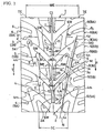
- FIG. 1 is a partial development view of a tread surface showing an embodiment of a pneumatic tire according to the present invention.
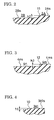
- FIG. 2 is an enlarged cross-sectional view of the bottom of a main groove taken along line II-II of FIG.1 .
- FIG. 3 is an enlarged cross-sectional view of the bottom of a second inclination groove taken along line III-III of FIG.1 .
- FIG. 4 is an enlarged cross-sectional view of the bottom of a first inclination groove taken along line IV-IV of FIG.1 .
- FIG. 1 there is shown a main part of a pneumatic tire according to the present invention; reference numeral 1 denotes a tread surface.
- the pneumatic tire has a rotation direction specified in one direction shown by arrow R.
- a main groove 2 extending straight in the circumferential direction T of the tire is provided on the equatorial plane CL of the tire in the tread surface 1.
- the right and left first inclination grooves 3 extend in a circularly curved manner beyond right and left ground contact ends TE of the tire on the tread surface 1, and are disposed at symmetrical positions with respect to the equatorial plane CL of the tire.
- the first inclination grooves 3 may extend in a straight manner instead of the circularly curved manner.
- Right and left second inclination grooves 4 which extend in an inclined manner with respect to the circumferential direction T of the tire, are provided on the opposite sides of the main groove 2 at prescribed intervals in the circumferential direction T of the tire.
- the second inclination grooves 4 extend to the ground contact ends TE of the tire in a circularly curved manner.
- Each second inclination groove 4 has a tire rotation direction side and a tire reverse rotation direction side which is more away from the main groove 2 than the tire rotation direction side, and has an inclination angle with respect to the circumferential direction T of the tire which gradually increases toward the tire reverse rotation direction side.
- the second inclination groove 4 extends across three first inclination grooves 3.
- the second inclination grooves 4, like the first inclination grooves 3, may extend in a straight manner instead of the circularly curved manner.
- a plurality of blocks 5 are defined by the main groove 2, right and left first inclination grooves 3, and right and left second inclination grooves 4 on the opposite sides of the main groove 2 in the tread surface 1. Also, a plurality of blocks 6 are defined by the right and left first inclination grooves 3 and right and left second inclination grooves 4 on the opposite shoulder sides of the tread surface 1.
- the right and left second inclination grooves 4 are disposed at symmetrical positions with respect to the equatorial plane CL of the tire, and have tire rotation direction side terminal ends 4x located in alternate blocks 5 (second blocks 5B) in the circumferential direction T of the tire and tire reverse rotation direction side terminal ends 4y located in alternate blocks 6 (first blocks 6A) in the circumferential direction T of the tire.
- the second inclination grooves 4 have tire rotation direction side portions 4m and tire reverse rotation direction side portions 4n, respectively.
- the blocks 5 comprise right and left first blocks 5A defined by the tire rotation direction side portions 4m of the right and left second inclination grooves 4, main groove 2 and right and left first inclination grooves 3, and right and left second blocks 5B defined by the tire reverse rotation direction side portions 4n of the right and left second inclination grooves 4, main groove 2 and right and left first inclination grooves 3.
- the right and left first blocks 5A and right and left second blocks 5B are alternately disposed in the circumferential direction T of the tire, respectively.
- Each first block 5A has a circumferential length LA measured along the circumferential direction T of the tire
- each second block 5B has a circumferential length LB measured along the circumferential direction T of the tire.
- the circumferential length LB of the second block 5B is greater than the circumferential length LA of the first block 5A.
- the second block 5B is greater also in width than the first block 5A.
- the first block 5A and second block 5B are each substantially in the form of a parallelogram in plan view and have obtuse-angled corners and acute-angled corners.
- Each of the acute-angled corners has a wall surface 5W which is circularly chamfered in cross section.
- Each block 5 has a tread surface section, where one sipe 7 extending straight along the widthwise direction of the tire is provided in its central region in the circumferential direction of the tire.
- the blocks 6 on each shoulder side comprise first blocks 6A which are adjacent to the first blocks 5A via the tire rotation direction side portions 4m of the second inclination grooves 4 and in which the tire reverse rotation direction side terminal ends 4y of the second inclination grooves 4 are located, and second blocks 6B adjacent to the second blocks 5B via the tire reverse rotation direction side portions 4n of the second inclination grooves 4.
- the first blocks 6A and second blocks 6B are alternately disposed in the circumferential direction T of the tire.
- the first blocks 6A and second blocks 6B have acute-angled corners and obtuse-angled corners facing the second inclination grooves 4.
- the acute-angled corners and obtuse-angled corners have wall surfaces 6W circularly chamfered in cross section.
- the first blocks 6A are greater in width than the second blocks 6B.
- Each block 6 has a tread surface section, where one subsidiary groove 8 extending in the widthwise direction of the tire is provided in its center in the circumferential direction of the tire.
- the subsidiary groove 8 extends in an inclined manner like the first inclination grooves 3 so that its inner terminal end 8x is away from a second inclination groove 4 adjacent thereto and its outer terminal end 8y is located on a design end of the tread surface 1.
- the subsidiary groove 8A disposed in the first block 6A extends longer inward in the widthwise direction of the tire than the subsidiary groove 8B disposed in the second block 6B.
- the subsidiary groove 8 is placed such that it does not communicate with the second inclination groove 4 as described above, whereby drainage characteristics are enhanced while a decrease in stiffness of the block 6 is suppressed.
- Each first block 6A has a tread surface section, where one sipe 9 extending straight from a second inclination groove 4 adjacent thereto outward in the widthwise direction of the tire is provided.
- the main groove 2 has first main groove portions 2A between the right and left first blocks 5A, and second main groove portions 2B between the right and left second blocks 5B.
- the first main groove portions 2A are each less in width than the second main groove portions 2B at a location of the tread surface 1.
- the first main groove portions 2A have the same widths as the second main groove portions 2B at the bottom of the main groove 2.
- the second main groove portions 2B each have a width which gradually increases toward the reverse rotation direction of the tire at the location of the tread surface 1.
- the right and left second blocks 5B each have a wall surface 5B1 beside the main groove 2.
- the wall surface 5B1 is inclined to the equatorial plane CL of the tire in cross section taken in a plane that contains the axis of rotation of the tire, and its inclination angle with respect to the equatorial plane CL of the tire gradually increases toward the reverse rotation direction of the tire.
- the widths of the first main groove portions 2A between the first blocks 5A are narrowed, whereby the first blocks 5A are larger in the widthwise direction, enabling stiffness thereof to be enhanced. Therefore, driving stability during running on a half dried road surface can be raised, enabling improvement of dry performance on a half dried road surface. If the widths of the second main groove portions 2B are narrowed to enhance stiffness of the second blocks 5B, differences in stiffness between the first blocks 5A and second blocks 5B are greater, creating a problem of uneven wear.
- the right and left second inclination grooves 4 are disposed at symmetrical positions with respect to the equatorial plane CL of the tire, whereby water can be expelled evenly sideways. Therefore, the tire has a drainage effect higher than one having second inclination grooves 4 offset in the circumferential direction of the tire.
- the symmetrically disposed second inclination grooves 4 compensate for a decrease in drainage characteristics arising from narrowing of the widths of the first main groove portions 2A, which can suppress reduction of drainage characteristics. Accordingly, wet performance as high as that of the prior art can be obtained.
- the widths of the first main groove portions 2A and second main groove portions 2B are preferably arranged such that the ratio W2/W1 of the maximum width W2 of each second main groove portion 2B to the minimum width W1 of each first main groove portion 2A is in the range of 2.5 to 4.5. If the ratio W2/W1 is under 2.5, reduction of wet performance and uneven wear are apt to occur. If the ratio W2/W1 is beyond 4.5, driving stability on a half dried road surface is deteriorated. Note that the first main groove portions 2A shown in FIG. 1 are constant in width, but the widths of the first main groove portions 2A may be varied.
- each second main groove portion 2B is preferably in the range of 6 % to 11 % of a ground contact width WE of the tire on the tread surface 1. If the width of the second main groove portion 2B is less than 6 % of the ground contact width WE of the tire, drainage characteristics are degraded. If the width of the second main groove portion 2B is greater than 11 % of the ground contact width WE of the tire, stiffness of the second blocks 5B is lowered, whereby driving stability during running on a half dried road surface can not be improved.
- the ratio LB/LA of the circumferential length LB of the second block 5B to the circumferential length LA of the first block 5A is preferably in the range of 1.1 to 1.9. If the ratio LB/LA is less than 1.1, stiffness of the second block 5B is lowered, whereby it is difficult to improve driving stability during running on a half dried road surface. If the ratio LB/LA is greater than 1.9, a stiffness difference between the blocks 5A and 5B is so great that uneven wear is apt to occur.
- Each of the first inclination grooves 3 has an inclination angle ⁇ with respect to the circumferential direction T of the tire, and the inclination angle ⁇ is preferably in the range of 40° to 60°. If the inclination angle ⁇ is under 40°, drainage characteristics are degraded. If the inclination angle ⁇ exceeds 60°, block stiffness is lowered, whereby driving stability during running on a half dried road surface is degraded.
- the first inclination groove 3 extends in a circularly curved manner as shown in FIG.
- the inclination angle ⁇ is an inclination angle, with respect to the circumferential direction T of the tire, of a straight line M passing an inner terminal end 3x of the first inclination groove 3 and a position 3z on the ground contact end TE of the tire which are located on the center line 3c of the first inclination groove 3.
- Each of the second inclination groove 4 has an inclination angle ⁇ with respect to the circumferential direction T of the tire, and the inclination angle ⁇ is preferably in the range of 10° to 30°. If the inclination angle ⁇ is under 10°, drainage characteristics are degraded when cornering. If the inclination angle ⁇ is beyond 30°, drainage characteristics are deteriorated when running straight.
- the inclination angle ⁇ is an inclination angle, with respect to the circumferential direction T of the tire, of a straight line N passing opposite terminal ends 4x and 4y of the second inclination groove 4 which are located on the center line 4c of the second inclination groove 4.
- the tread surface 1 has a center region 1C between positions away right and left from the equatorial plane CL of the tire by a distance of 55/2 % of the ground contact width WE of the tire.
- the center region 1C has a groove area percentage, which is preferably in the range of 50 % to 60 %. If the groove area percentage is under 50%, drainage characteristics are degraded. If the groove area percentage is beyond 60%, block stiffness is lowered, whereby it is difficult to improve driving stability during running on a half dried road surface.
- a bottom-raising portion 11 is preferably provided in each first main groove portion 2A in such a manner that the first main groove portion 2A having a bottom 2As is less in depth than the second main groove portion 2B having a bottom 2Bs, thereby connecting two first blocks 5A standing on the opposite sides of the main groove 2 by the bottom-raising portion 11. Also, as shown in FIG. 2 , as shown in FIG. 2 , a bottom-raising portion 11 is preferably provided in each first main groove portion 2A in such a manner that the first main groove portion 2A having a bottom 2As is less in depth than the second main groove portion 2B having a bottom 2Bs, thereby connecting two first blocks 5A standing on the opposite sides of the main groove 2 by the bottom-raising portion 11. Also, as shown in FIG.
- a bottom-raising portion 12 is preferably provided in each second inclination groove 4 in such a manner that the tire rotation direction side portion 4m of the second inclination groove 4 having a bottom 4ms is less in depth than the tire reverse rotation direction side portion 4n of the second inclination groove 4 having a bottom 4ns, thereby connecting a first blocks 5A and a first block 6A standing in the widthwise direction of the tire by the bottom-raising portion 12.
- This allows stiffness of the first block 5A to be further enhanced, enabling movement thereof to be suppressed. As a result, handle operability during running on a half dried road surface can be further raised.
- the first inclination grooves 3 are preferably arranged such that every other first inclination groove in the circumferential direction T of the tire is partially less in depth on the shoulder side of the tire.
- the every other first inclination groove is a first inclination groove 3A between a first block 6A and a second block 6B adjacent thereto in the rotation direction of the tire.
- the first inclination groove 3A has a groove portion 3A1 located outward in the widthwise direction of the tire from the ground contact end TE of the tire.
- a bottom-raising portion 10 is provided in the groove portion 3A1 in such a manner that the groove portion 3A having a bottom 3A1s is less in depth than the other groove portion of the first inclination groove 3A having a bottom.
- the bottom-raising portion 10 is located outward, in the widthwise direction of the tire, of an inclination groove 4 crossing to the first inclination groove 3A.
- the two blocks 6A and 6B adjacent in the circumferential direction T of the tire are connected by the bottom-raising portion 10, thereby allowing stiffness of the blocks 6A and 6B to be increased. This enables block stiffness in the shoulder regions of the tread surface 1 to be increased, whereby driving stability during running on a half dried road surface can be enhanced.
- the bottom-raising portion 10 may be provided in the other first inclination groove 3B instead of the first inclination groove 3A.
- the bottom-raising portion 10 has a height h1, the bottom-raising portion 11 has a height h2, and the bottom-raising portion 12 has a height h3. It is preferable in terms of an effective increase in block stiffness without noticeable deterioration of drainage characteristics that the height h1 be in the range of 30 % to 70 % of the depth of the first inclination groove 3A from the bottom thereof, the height h2 be in the range of 30 % to 70 % of the depth of the main groove 2 from the bottom thereof, and the height h3 be in the range of 30 % to 70 % of the depth of the second inclination groove 4 from the bottom thereof.
- the depths of the main groove 2, first inclination grooves 3 and second inclination grooves 4 can be in the range of 4 mm to 8.5 mm, respectively.
- each second inclination groove 4 is provided so as to extend across three first inclination grooves 3.
- the second inclination groove 4 may be disposed so as to extend across more than three first inclination grooves 3.
- the upper limit of the number of the first inclination grooves 3 that the second inclination groove 4 goes across is preferably eight at a maximum from the viewpoint of block stiffness although it is different in tire size.
- the present invention is preferably applicable to tires for racing carts in particular requiring high wet performance when running on a rainy day; however, the present invention is also suitable for application to pneumatic tires used for other vehicles as a matter of course.
- the tire ground contact width WE and the tire ground contact ends TE referred in the present invention are a maximum ground contact width of the tread surface 1 and ground contact ends thereof when measured under such conditions that, when the tire is used for racing carts and has a tire size of 4.5x10.0-5, it is mounted on a rim having a service rim width of 4.5 inches and inflated to an air pressure of 100 kPa, and a load of 0.45 kN is applied thereto, and that, when the tire is used for racing carts and has a tire size of 6.0x11.0-5, it is mounted on a rim having a service rim width of 6.5 inches and inflated to an air pressure of 100 kPa, and a load of 0.65 kN is applied thereto.
- the tire ground contact width WE and the tire ground contact ends TE referred in the present invention are a maximum ground contact width of the tread surface 1 and ground contact ends thereof when measured under such conditions that the tire is mounted on a standard rim specified by JATMA (Japanese Automobile tire manufacturer association) and inflated to an air pressure corresponding to the maximum load capacity specified by JATMA, and a load equivalent to 75 % of the maximum load capacity is applied thereto.
- JATMA Japanese Automobile tire manufacturer association
- test tires according to the present invention tires 1 and 2 (present examples 1 and 2) and control tire (control example), each used for a front tire having a tire size of 4.5x10.0-5, each used for a rear tire having a tire size of 6.0x11.0-5, the present invention tire 1 having a structure shown in FIG. 1 , the present invention tire 2 having the same structure as the present invention tire 1 except that there was no bottom-raising portion on the bottoms of the main groove, first inclination grooves and second inclination grooves, the control tire having the same structure as the present invention tire 2 except that the right and left second inclination grooves were disposed in positions offset in the circumferential direction of the tire and the main groove was constant in width.
- the ratio W2/W1 of the maximum width W2 of each second main groove portion to the minimum width W1 of each first main groove portion is 3.5
- the ratio LB/LA of the circumferential length LB of each second block to the circumferential length LA of each first block is 1.5
- the inclination angle ⁇ of each first inclination groove with respect to the circumferential direction of the tire is 50°
- the inclination angle ⁇ of each second inclination groove with respect to the circumferential direction of the tire is 20°.
- the width of each second main groove portion gradually increases in the range of 6 % to 11% of the tire ground contact width WE.
- the groove area percentage of the center region is 55 %.
- the depths of the main groove, first inclination grooves and second inclination grooves are 6 mm, respectively.
- the depths of parts of the main groove, first inclination grooves and second inclination grooves in which bottom-raising portions are provided to reduce their depths are 3 mm, respectively.
- the depth of the main groove is 8.5 % of the tire ground contact width WE, and the groove area percentage of the center region is 55 %.
- test tires were assembled to rims corresponding thereto, inflated to an air pressure of 100 kPa, and mounted on a vehicle (racing cart) of 125 cc displacement. Evaluation testing for wet performance, and driving stability and handle operability on a half dried road surface was carried out according to the testing methods shown below, obtaining the results shown in Table 1.
- the car was run on a wet road test course having a water depth of 2 mm to 3 mm, and feeling testing for driving stability was conducted by a test driver.
- the evaluation result thereof is represented by an index where the control tire is 100. As the index is greater, wet performance is better. Note that the index range of 98 to 102 is a range equivalent to the prior art level.
- the car was run on a test course having half dried conditions, and feeling testing for driving stability and handle operability was conducted by a test driver.
- the evaluation results thereof are respectively represented by an index where the control tire is 100. As the index is greater, each performance is better.
- Presnet Example 1 Presnet Example 2 Control Example Wet Performance 98 105 100 Half Dried Road Surface Driving Stability 110 105 100 Handle Operability 115 105 100
Landscapes
- Engineering & Computer Science (AREA)
- Mechanical Engineering (AREA)
- Tires In General (AREA)
Abstract
Description
- The present invention relates to pneumatic tires, and more particularly, to a pneumatic tire which can improve dry performance on a half dried road surface while maintaining high wet performance.
- As one of pneumatic tires preferably used for racing cart tires which require high drainage characteristics when running straight and cornering on a rainy day, there has conventionally been known a pneumatic tire having a tread pattern in which a main groove extending in the circumferential direction of the tire is provided on the equatorial plane of the tire and two types of inclination grooves are adequately disposed on the opposite sides of the main groove (see Japanese Patent Application Kokai Publication
2003-175705 - A racing course for the carts includes half dried road surface sections having wet road surface conditions without water, and wet road surface sections having water thereon when running on a rainy day. When the carts run thereon, the carts may run also on the half dried road surface sections. In this case, the above pneumatic tire providing high wet performance by the main groove and inclination grooves must degrade dry performance (driving stability) on the half dried road surface sections which conflicts with wet performance, requiring improvement thereof.
- An object of the present invention is to provide a pneumatic tire capable of improving dry performance on a half dried road surface while maintaining high wet performance.
- In order to achieve the above object, the present invention provides a pneumatic tire having a rotation direction specified in one direction and a tread surface, a main groove extending in a circumferential direction of the tire being provided on an equatorial plane of the tire in the tread surface, right and left first inclination grooves being disposed at prescribed intervals in the circumferential direction of the tire, the right and left first inclination grooves extending from the main groove toward opposite sides of the tire in a widthwise direction of the tire beyond ground contact ends of the tire in an inclined manner toward a reverse rotation direction of the tire, right and left second inclination grooves being provided on opposite sides of the main groove at prescribed intervals in the circumferential direction of the tire, the right and left second inclination grooves extending across the right and left first inclination grooves in such an inclined manner with respect to the circumferential direction of the tire that tire reverse rotation direction sides of the second inclination grooves are more away from the main groove than tire rotation direction sides of the second inclination grooves, blocks being defined on the opposite sides of the main groove by the main groove, right and left first inclination grooves and right and left second inclination grooves, wherein: the right and left second inclination grooves are disposed at symmetrical positions with respect to the equatorial plane of the tire; the blocks comprise right and left first blocks defined by tire rotation direction side portions of the right and left second inclination grooves, main groove and right and left first inclination grooves, and right and left second blocks defined by tire reverse rotation direction side portions of the right and left second inclination grooves, main groove and right and left first inclination grooves, the first blocks each having a circumferential length LA, the second blocks each having a circumferential length LB, the circumferential length LB being greater than the circumferential length LA; and the main groove has first main groove portions between the right and left first blocks and second main groove portions between the right and left second blocks, widths of the first main groove portions being less than widths of the second main groove portions.
- According to the present invention mentioned above, by narrowing the widths of the first main groove portions between the first blocks, the first blocks are larger in the widthwise direction, enabling stiffness thereof to be enhanced. Therefore, driving stability during running on a half dried road surface can be raised, enabling improvement of dry performance on a half dried road surface.
- On the other hand, by disposing the right and left second inclination grooves at symmetrical positions, water can be expelled evenly sideways during running on a wet road surface. Therefore, the tire has a drainage effect higher than one having second inclination grooves offset in the circumferential direction of the tire. As a result, the arrangement of the second inclination grooves compensates for a decrease in drainage characteristics arising from narrowing of the widths of the first main groove portions, which can suppress reduction of drainage characteristics. Accordingly, wet performance as high as that of the prior art can be obtained.
-
FIG. 1 is a partial development view of a tread surface showing an embodiment of a pneumatic tire according to the present invention.
FIG. 2 is an enlarged cross-sectional view of the bottom of a main groove taken along line II-II ofFIG.1 .
FIG. 3 is an enlarged cross-sectional view of the bottom of a second inclination groove taken along line III-III ofFIG.1 .
FIG. 4 is an enlarged cross-sectional view of the bottom of a first inclination groove taken along line IV-IV ofFIG.1 . - An embodiment of the present invention will be described in detail below with reference to the attached drawings.
- Referring to
FIG. 1 , there is shown a main part of a pneumatic tire according to the present invention; reference numeral 1 denotes a tread surface. The pneumatic tire has a rotation direction specified in one direction shown by arrow R. Amain groove 2 extending straight in the circumferential direction T of the tire is provided on the equatorial plane CL of the tire in the tread surface 1. Right and leftfirst inclination grooves 3, which extend from themain groove 2 toward the opposite sides of the tire in the widthwise direction of the tire in an inclined manner toward the reverse rotation direction of the tire, are disposed at prescribed intervals in the circumferential direction T of the tire. The right and leftfirst inclination grooves 3 extend in a circularly curved manner beyond right and left ground contact ends TE of the tire on the tread surface 1, and are disposed at symmetrical positions with respect to the equatorial plane CL of the tire. Thefirst inclination grooves 3 may extend in a straight manner instead of the circularly curved manner. - Right and left
second inclination grooves 4, which extend in an inclined manner with respect to the circumferential direction T of the tire, are provided on the opposite sides of themain groove 2 at prescribed intervals in the circumferential direction T of the tire. Thesecond inclination grooves 4 extend to the ground contact ends TE of the tire in a circularly curved manner. Eachsecond inclination groove 4 has a tire rotation direction side and a tire reverse rotation direction side which is more away from themain groove 2 than the tire rotation direction side, and has an inclination angle with respect to the circumferential direction T of the tire which gradually increases toward the tire reverse rotation direction side. Thesecond inclination groove 4 extends across threefirst inclination grooves 3. The second inclination grooves 4, like thefirst inclination grooves 3, may extend in a straight manner instead of the circularly curved manner. - A plurality of
blocks 5 are defined by themain groove 2, right and leftfirst inclination grooves 3, and right and leftsecond inclination grooves 4 on the opposite sides of themain groove 2 in the tread surface 1. Also, a plurality ofblocks 6 are defined by the right and leftfirst inclination grooves 3 and right and leftsecond inclination grooves 4 on the opposite shoulder sides of the tread surface 1. - The right and left
second inclination grooves 4 are disposed at symmetrical positions with respect to the equatorial plane CL of the tire, and have tire rotation directionside terminal ends 4x located in alternate blocks 5 (second blocks 5B) in the circumferential direction T of the tire and tire reverse rotation direction side terminal ends 4y located in alternate blocks 6 (first blocks 6A) in the circumferential direction T of the tire. Thesecond inclination grooves 4 have tire rotationdirection side portions 4m and tire reverse rotationdirection side portions 4n, respectively. - The
blocks 5 comprise right and leftfirst blocks 5A defined by the tire rotationdirection side portions 4m of the right and leftsecond inclination grooves 4,main groove 2 and right and leftfirst inclination grooves 3, and right and leftsecond blocks 5B defined by the tire reverse rotationdirection side portions 4n of the right and leftsecond inclination grooves 4,main groove 2 and right and leftfirst inclination grooves 3. The right and leftfirst blocks 5A and right and leftsecond blocks 5B are alternately disposed in the circumferential direction T of the tire, respectively. - Each
first block 5A has a circumferential length LA measured along the circumferential direction T of the tire, and eachsecond block 5B has a circumferential length LB measured along the circumferential direction T of the tire. The circumferential length LB of thesecond block 5B is greater than the circumferential length LA of thefirst block 5A. Thesecond block 5B is greater also in width than thefirst block 5A. Thefirst block 5A andsecond block 5B are each substantially in the form of a parallelogram in plan view and have obtuse-angled corners and acute-angled corners. Each of the acute-angled corners has awall surface 5W which is circularly chamfered in cross section. Eachblock 5 has a tread surface section, where onesipe 7 extending straight along the widthwise direction of the tire is provided in its central region in the circumferential direction of the tire. - The
blocks 6 on each shoulder side comprisefirst blocks 6A which are adjacent to thefirst blocks 5A via the tire rotationdirection side portions 4m of thesecond inclination grooves 4 and in which the tire reverse rotation direction side terminal ends 4y of thesecond inclination grooves 4 are located, andsecond blocks 6B adjacent to thesecond blocks 5B via the tire reverse rotationdirection side portions 4n of thesecond inclination grooves 4. Thefirst blocks 6A andsecond blocks 6B are alternately disposed in the circumferential direction T of the tire. Thefirst blocks 6A andsecond blocks 6B have acute-angled corners and obtuse-angled corners facing thesecond inclination grooves 4. The acute-angled corners and obtuse-angled corners havewall surfaces 6W circularly chamfered in cross section. Thefirst blocks 6A are greater in width than thesecond blocks 6B. - Each
block 6 has a tread surface section, where onesubsidiary groove 8 extending in the widthwise direction of the tire is provided in its center in the circumferential direction of the tire. Thesubsidiary groove 8 extends in an inclined manner like thefirst inclination grooves 3 so that itsinner terminal end 8x is away from asecond inclination groove 4 adjacent thereto and itsouter terminal end 8y is located on a design end of the tread surface 1. Thesubsidiary groove 8A disposed in thefirst block 6A extends longer inward in the widthwise direction of the tire than thesubsidiary groove 8B disposed in thesecond block 6B. Thesubsidiary groove 8 is placed such that it does not communicate with thesecond inclination groove 4 as described above, whereby drainage characteristics are enhanced while a decrease in stiffness of theblock 6 is suppressed. Eachfirst block 6A has a tread surface section, where one sipe 9 extending straight from asecond inclination groove 4 adjacent thereto outward in the widthwise direction of the tire is provided. - The
main groove 2 has firstmain groove portions 2A between the right and leftfirst blocks 5A, and secondmain groove portions 2B between the right and leftsecond blocks 5B. The firstmain groove portions 2A are each less in width than the secondmain groove portions 2B at a location of the tread surface 1. The firstmain groove portions 2A have the same widths as the secondmain groove portions 2B at the bottom of themain groove 2. The secondmain groove portions 2B each have a width which gradually increases toward the reverse rotation direction of the tire at the location of the tread surface 1. The right and leftsecond blocks 5B each have a wall surface 5B1 beside themain groove 2. The wall surface 5B1 is inclined to the equatorial plane CL of the tire in cross section taken in a plane that contains the axis of rotation of the tire, and its inclination angle with respect to the equatorial plane CL of the tire gradually increases toward the reverse rotation direction of the tire. - According to the present invention described above, the widths of the first
main groove portions 2A between thefirst blocks 5A are narrowed, whereby thefirst blocks 5A are larger in the widthwise direction, enabling stiffness thereof to be enhanced. Therefore, driving stability during running on a half dried road surface can be raised, enabling improvement of dry performance on a half dried road surface. If the widths of the secondmain groove portions 2B are narrowed to enhance stiffness of thesecond blocks 5B, differences in stiffness between thefirst blocks 5A andsecond blocks 5B are greater, creating a problem of uneven wear. - On the other hand, the right and left
second inclination grooves 4 are disposed at symmetrical positions with respect to the equatorial plane CL of the tire, whereby water can be expelled evenly sideways. Therefore, the tire has a drainage effect higher than one havingsecond inclination grooves 4 offset in the circumferential direction of the tire. As a result, the symmetrically disposedsecond inclination grooves 4 compensate for a decrease in drainage characteristics arising from narrowing of the widths of the firstmain groove portions 2A, which can suppress reduction of drainage characteristics. Accordingly, wet performance as high as that of the prior art can be obtained. - By gradually increasing the widths of the second
main groove portions 2B toward the reverse rotation direction of the tire, a drainage effect arising from the secondmain groove portions 2B can be enhanced. On the other hand, by gradually increasing the inclination angles, with respect to the equatorial plane CL of the tire, of the wall surfaces 5B1 of the right and leftsecond blocks 5B facing the gradually widening secondmain groove portions 2B toward the reverse rotation direction of the tire, stiffness of thesecond blocks 5B does not decrease when the widths of the secondmain groove portions 2B is gradually increased to thereby reduce the widths of thesecond blocks 5B. - When the tire is used for a front tire, heat generation of the
first blocks 5A is suppressed, and movements of thefirst blocks 5A can be less than before. Therefore, handle operability during running on a half dried road surface can be raised, enabling further improvement of dry performance on a half dried road surface. - In the present invention, the widths of the first
main groove portions 2A and secondmain groove portions 2B are preferably arranged such that the ratio W2/W1 of the maximum width W2 of each secondmain groove portion 2B to the minimum width W1 of each firstmain groove portion 2A is in the range of 2.5 to 4.5. If the ratio W2/W1 is under 2.5, reduction of wet performance and uneven wear are apt to occur. If the ratio W2/W1 is beyond 4.5, driving stability on a half dried road surface is deteriorated. Note that the firstmain groove portions 2A shown inFIG. 1 are constant in width, but the widths of the firstmain groove portions 2A may be varied. - The width of each second
main groove portion 2B is preferably in the range of 6 % to 11 % of a ground contact width WE of the tire on the tread surface 1. If the width of the secondmain groove portion 2B is less than 6 % of the ground contact width WE of the tire, drainage characteristics are degraded. If the width of the secondmain groove portion 2B is greater than 11 % of the ground contact width WE of the tire, stiffness of thesecond blocks 5B is lowered, whereby driving stability during running on a half dried road surface can not be improved. - The ratio LB/LA of the circumferential length LB of the
second block 5B to the circumferential length LA of thefirst block 5A is preferably in the range of 1.1 to 1.9. If the ratio LB/LA is less than 1.1, stiffness of thesecond block 5B is lowered, whereby it is difficult to improve driving stability during running on a half dried road surface. If the ratio LB/LA is greater than 1.9, a stiffness difference between theblocks - Each of the
first inclination grooves 3 has an inclination angle α with respect to the circumferential direction T of the tire, and the inclination angle α is preferably in the range of 40° to 60°. If the inclination angle α is under 40°, drainage characteristics are degraded. If the inclination angle α exceeds 60°, block stiffness is lowered, whereby driving stability during running on a half dried road surface is degraded. When thefirst inclination groove 3 extends in a circularly curved manner as shown inFIG. 1 , the inclination angle α is an inclination angle, with respect to the circumferential direction T of the tire, of a straight line M passing an innerterminal end 3x of thefirst inclination groove 3 and aposition 3z on the ground contact end TE of the tire which are located on the center line 3c of thefirst inclination groove 3. - Each of the
second inclination groove 4 has an inclination angle β with respect to the circumferential direction T of the tire, and the inclination angle β is preferably in the range of 10° to 30°. If the inclination angle β is under 10°, drainage characteristics are degraded when cornering. If the inclination angle β is beyond 30°, drainage characteristics are deteriorated when running straight. When thesecond inclination groove 4 extends in a circularly curved manner as shown inFIG. 1 , the inclination angle β is an inclination angle, with respect to the circumferential direction T of the tire, of a straight line N passing opposite terminal ends 4x and 4y of thesecond inclination groove 4 which are located on the center line 4c of thesecond inclination groove 4. - The tread surface 1 has a
center region 1C between positions away right and left from the equatorial plane CL of the tire by a distance of 55/2 % of the ground contact width WE of the tire. Thecenter region 1C has a groove area percentage, which is preferably in the range of 50 % to 60 %. If the groove area percentage is under 50%, drainage characteristics are degraded. If the groove area percentage is beyond 60%, block stiffness is lowered, whereby it is difficult to improve driving stability during running on a half dried road surface. - When the pneumatic tire described above is used for a front tire of a racing cart or the like, it is preferable that block stiffness be higher. In this case, as shown in
FIG. 2 , a bottom-raisingportion 11 is preferably provided in each firstmain groove portion 2A in such a manner that the firstmain groove portion 2A having a bottom 2As is less in depth than the secondmain groove portion 2B having a bottom 2Bs, thereby connecting twofirst blocks 5A standing on the opposite sides of themain groove 2 by the bottom-raisingportion 11. Also, as shown inFIG. 3 , a bottom-raisingportion 12 is preferably provided in eachsecond inclination groove 4 in such a manner that the tire rotationdirection side portion 4m of thesecond inclination groove 4 having a bottom 4ms is less in depth than the tire reverse rotationdirection side portion 4n of thesecond inclination groove 4 having a bottom 4ns, thereby connecting afirst blocks 5A and afirst block 6A standing in the widthwise direction of the tire by the bottom-raisingportion 12. This allows stiffness of thefirst block 5A to be further enhanced, enabling movement thereof to be suppressed. As a result, handle operability during running on a half dried road surface can be further raised. - In the case where driving stability during running on a half dried road surface is further improved, as shown in
FIGS. 1 and4 , thefirst inclination grooves 3 are preferably arranged such that every other first inclination groove in the circumferential direction T of the tire is partially less in depth on the shoulder side of the tire. InFIG. 1 , the every other first inclination groove is afirst inclination groove 3A between afirst block 6A and asecond block 6B adjacent thereto in the rotation direction of the tire. Thefirst inclination groove 3A has a groove portion 3A1 located outward in the widthwise direction of the tire from the ground contact end TE of the tire. A bottom-raisingportion 10 is provided in the groove portion 3A1 in such a manner that thegroove portion 3A having a bottom 3A1s is less in depth than the other groove portion of thefirst inclination groove 3A having a bottom. The bottom-raisingportion 10 is located outward, in the widthwise direction of the tire, of aninclination groove 4 crossing to thefirst inclination groove 3A. The twoblocks portion 10, thereby allowing stiffness of theblocks portion 10 may be provided in the otherfirst inclination groove 3B instead of thefirst inclination groove 3A. - The bottom-raising
portion 10 has a height h1, the bottom-raisingportion 11 has a height h2, and the bottom-raisingportion 12 has a height h3. It is preferable in terms of an effective increase in block stiffness without noticeable deterioration of drainage characteristics that the height h1 be in the range of 30 % to 70 % of the depth of thefirst inclination groove 3A from the bottom thereof, the height h2 be in the range of 30 % to 70 % of the depth of themain groove 2 from the bottom thereof, and the height h3 be in the range of 30 % to 70 % of the depth of thesecond inclination groove 4 from the bottom thereof. The depths of themain groove 2,first inclination grooves 3 andsecond inclination grooves 4 can be in the range of 4 mm to 8.5 mm, respectively. - In the embodiment described above, each
second inclination groove 4 is provided so as to extend across threefirst inclination grooves 3. However, thesecond inclination groove 4 may be disposed so as to extend across more than threefirst inclination grooves 3. The upper limit of the number of thefirst inclination grooves 3 that thesecond inclination groove 4 goes across is preferably eight at a maximum from the viewpoint of block stiffness although it is different in tire size. - The present invention is preferably applicable to tires for racing carts in particular requiring high wet performance when running on a rainy day; however, the present invention is also suitable for application to pneumatic tires used for other vehicles as a matter of course.
- It should be noted that the tire ground contact width WE and the tire ground contact ends TE referred in the present invention are a maximum ground contact width of the tread surface 1 and ground contact ends thereof when measured under such conditions that, when the tire is used for racing carts and has a tire size of 4.5x10.0-5, it is mounted on a rim having a service rim width of 4.5 inches and inflated to an air pressure of 100 kPa, and a load of 0.45 kN is applied thereto, and that, when the tire is used for racing carts and has a tire size of 6.0x11.0-5, it is mounted on a rim having a service rim width of 6.5 inches and inflated to an air pressure of 100 kPa, and a load of 0.65 kN is applied thereto. When the tire is a tire other than the tire for racing carts, the tire ground contact width WE and the tire ground contact ends TE referred in the present invention are a maximum ground contact width of the tread surface 1 and ground contact ends thereof when measured under such conditions that the tire is mounted on a standard rim specified by JATMA (Japanese Automobile tire manufacturer association) and inflated to an air pressure corresponding to the maximum load capacity specified by JATMA, and a load equivalent to 75 % of the maximum load capacity is applied thereto.
- Prepared respectively were test tires according to the present invention tires 1 and 2 (present examples 1 and 2) and control tire (control example), each used for a front tire having a tire size of 4.5x10.0-5, each used for a rear tire having a tire size of 6.0x11.0-5, the present invention tire 1 having a structure shown in
FIG. 1 , thepresent invention tire 2 having the same structure as the present invention tire 1 except that there was no bottom-raising portion on the bottoms of the main groove, first inclination grooves and second inclination grooves, the control tire having the same structure as thepresent invention tire 2 except that the right and left second inclination grooves were disposed in positions offset in the circumferential direction of the tire and the main groove was constant in width. - In each of the
present invention tires 1 and 2, the ratio W2/W1 of the maximum width W2 of each second main groove portion to the minimum width W1 of each first main groove portion is 3.5, the ratio LB/LA of the circumferential length LB of each second block to the circumferential length LA of each first block is 1.5, the inclination angle α of each first inclination groove with respect to the circumferential direction of the tire is 50°, and the inclination angle β of each second inclination groove with respect to the circumferential direction of the tire is 20°. The width of each second main groove portion gradually increases in the range of 6 % to 11% of the tire ground contact width WE. The groove area percentage of the center region is 55 %. - In each of the
present invention tires 1 and 2, the depths of the main groove, first inclination grooves and second inclination grooves are 6 mm, respectively. In the present invention tire 1, the depths of parts of the main groove, first inclination grooves and second inclination grooves in which bottom-raising portions are provided to reduce their depths are 3 mm, respectively. In the control tire, the depth of the main groove is 8.5 % of the tire ground contact width WE, and the groove area percentage of the center region is 55 %. - The respective test tires were assembled to rims corresponding thereto, inflated to an air pressure of 100 kPa, and mounted on a vehicle (racing cart) of 125 cc displacement. Evaluation testing for wet performance, and driving stability and handle operability on a half dried road surface was carried out according to the testing methods shown below, obtaining the results shown in Table 1.
- The car was run on a wet road test course having a water depth of 2 mm to 3 mm, and feeling testing for driving stability was conducted by a test driver. The evaluation result thereof is represented by an index where the control tire is 100. As the index is greater, wet performance is better. Note that the index range of 98 to 102 is a range equivalent to the prior art level.
- The car was run on a test course having half dried conditions, and feeling testing for driving stability and handle operability was conducted by a test driver. The evaluation results thereof are respectively represented by an index where the control tire is 100. As the index is greater, each performance is better.
-
[Table 1] Presnet Example 1 Presnet Example 2 Control Example Wet Performance 98 105 100 Half Dried Road Surface Driving Stability 110 105 100 Handle Operability 115 105 100 - From Table 1, it is understood that the present invention tires can improve dry performance on a half dried road surface while maintaining wet performance at the same level as the prior art.
Claims (12)
- A pneumatic tire having a rotation direction specified in one direction and a tread surface, a main groove extending in a circumferential direction of the tire being provided on an equatorial plane of the tire in the tread surface, right and left first inclination grooves being disposed at prescribed intervals in the circumferential direction of the tire, the right and left first inclination grooves extending from the main groove toward opposite sides of the tire in a widthwise direction of the tire beyond ground contact ends of the tire in an inclined manner toward a reverse rotation direction of the tire, right and left second inclination grooves being provided on opposite sides of the main groove at prescribed intervals in the circumferential direction of the tire, the right and left second inclination grooves extending across the right and left first inclination grooves in such an inclined manner with respect to the circumferential direction of the tire that tire reverse rotation direction sides of the second inclination grooves are more away from the main groove than tire rotation direction sides of the second inclination grooves, blocks being defined on the opposite sides of the main groove by the main groove, right and left first inclination grooves and right and left second inclination grooves, wherein:the right and left second inclination grooves are disposed at symmetrical positions with respect to the equatorial plane of the tire;the blocks comprise right and left first blocks defined by tire rotation direction side portions of the right and left second inclination grooves, main groove and right and left first inclination grooves, and right and left second blocks defined by tire reverse rotation direction side portions of the right and left second inclination grooves, main groove and right and left first inclination grooves, the first blocks each having a circumferential length LA, the second blocks each having a circumferential length LB, the circumferential length LB being greater than the circumferential length LA; andthe main groove has first main groove portions between the right and left first blocks and second main groove portions between the right and left second blocks, widths of the first main groove portions being less than widths of the second main groove portions.
- The pneumatic tire according to claim 1, wherein the widths of the second main groove portions gradually increase toward the reverse rotation direction of the tire.
- The pneumatic tire according to claim 2, wherein the right and left second blocks each have a wall surface beside the main groove, the wall surface being inclined to the equatorial plane of the tire in cross section taken in a plane that contains an axis of rotation of the tire and having an inclination angle with respect to the equatorial plane of the tire gradually increasing toward the reverse rotation direction of the tire.
- The pneumatic tire according to claim 1, 2 or 3, wherein a ratio W2/W1 of a maximum width W2 of each second main groove portion to a minimum width W1 of each first main groove portion is 2.5 to 4.5.
- The pneumatic tire according to any one of claims 1 to 4, wherein a ratio LB/LA of the circumferential length LB of the second block to the circumferential length LA of the first block is 1.1 to 1.9.
- The pneumatic tire according to any one of claims 1 to 5, wherein the first inclination grooves each have an inclination angle of 40° to 60° with respect to the circumferential direction of the tire, and wherein the second inclination grooves each have an inclination angle of 10° to 30° with respect to the circumferential direction of the tire.
- The pneumatic tire according to any one of claims 1 to 6, wherein each second inclination groove extends across three first inclination grooves, the second inclination groove having opposite terminal ends located within blocks.
- The pneumatic tire according to any one of claims 1 to 7, wherein the tread surface has a center region between positions away right and left from the equatorial plane of the tire by a distance of 55/2 % of a ground contact width of the tire, the center region having a groove area percentage of 50 % to 60 %.
- The pneumatic tire according to any one of claims 1 to 8, wherein the first main groove portions are less in depth than the second main groove portions.
- The pneumatic tire according to any one of claims 1 to 9, wherein the tire rotation direction side portions of the second inclination grooves are less in depth than the tire reverse rotation direction side portions of the second inclination grooves.
- The pneumatic tire according to any one of claims 1 to 10, wherein every other first inclination groove in the circumferential direction of the tire is partially less in depth on a shoulder side of the tire.
- The pneumatic tire according to any one of claims 1 to 11, wherein a sipe extending in the widthwise direction of the tire is provided in each of the first blocks and second blocks.
Applications Claiming Priority (1)
| Application Number | Priority Date | Filing Date | Title |
|---|---|---|---|
| JP2008049436A JP4137178B1 (en) | 2008-02-29 | 2008-02-29 | Pneumatic tire |
Publications (2)
| Publication Number | Publication Date |
|---|---|
| EP2095975A1 true EP2095975A1 (en) | 2009-09-02 |
| EP2095975B1 EP2095975B1 (en) | 2010-09-01 |
Family
ID=39758349
Family Applications (1)
| Application Number | Title | Priority Date | Filing Date |
|---|---|---|---|
| EP08019835A Ceased EP2095975B1 (en) | 2008-02-29 | 2008-11-13 | Pneumatic tire |
Country Status (4)
| Country | Link |
|---|---|
| US (1) | US7647958B2 (en) |
| EP (1) | EP2095975B1 (en) |
| JP (1) | JP4137178B1 (en) |
| TW (1) | TWI364369B (en) |
Families Citing this family (6)
| Publication number | Priority date | Publication date | Assignee | Title |
|---|---|---|---|---|
| WO2009069585A1 (en) * | 2007-11-28 | 2009-06-04 | Sumitomo Rubber Industries, Ltd. | Pneumatic tire |
| JP4996661B2 (en) * | 2009-10-15 | 2012-08-08 | 住友ゴム工業株式会社 | Pneumatic tire |
| JP6699193B2 (en) * | 2016-01-21 | 2020-05-27 | 住友ゴム工業株式会社 | Pneumatic tire |
| JP7145066B2 (en) * | 2018-12-27 | 2022-09-30 | Toyo Tire株式会社 | pneumatic tire |
| CN115551724A (en) * | 2020-06-25 | 2022-12-30 | 横滨橡胶株式会社 | Pneumatic tire |
| US20230339267A1 (en) * | 2020-06-25 | 2023-10-26 | The Yokohama Rubber Co., Ltd. | Pneumatic tire |
Citations (6)
| Publication number | Priority date | Publication date | Assignee | Title |
|---|---|---|---|---|
| EP1075971A1 (en) * | 1999-02-26 | 2001-02-14 | Bridgestone Corporation | Pneumatic tire |
| EP1116604A2 (en) * | 2000-01-17 | 2001-07-18 | Bridgestone Corporation | Pneumatic tires |
| US20030024621A1 (en) * | 2001-08-03 | 2003-02-06 | Neugebauer Paul M. | Pneumatic tire having tapered tie bars |
| US20030111151A1 (en) * | 2001-12-13 | 2003-06-19 | Takeo Masaki | Pneumatic tire |
| EP1437237A2 (en) * | 2003-01-07 | 2004-07-14 | Sumitomo Rubber Industries Ltd. | Pneumatic tire |
| EP1752314A1 (en) * | 2004-05-27 | 2007-02-14 | Bridgestone Corporation | Pneumatic tire |
Family Cites Families (16)
| Publication number | Priority date | Publication date | Assignee | Title |
|---|---|---|---|---|
| GB738143A (en) * | 1953-06-15 | 1955-10-05 | Sigurd Ingemann Olsen | Improvements in the treads of tyres for motor vehicles |
| JPH01204804A (en) * | 1988-02-09 | 1989-08-17 | Bridgestone Corp | Directional tread equipped pneumatic tire and application thereof |
| JPH0332907A (en) * | 1989-06-30 | 1991-02-13 | Yokohama Rubber Co Ltd:The | Pneumatic tire |
| JP2824672B2 (en) | 1989-08-25 | 1998-11-11 | 横浜ゴム株式会社 | Pneumatic tire |
| IT1250624B (en) * | 1991-07-04 | 1995-04-21 | Pirelli | RADIAL TIRE WITH SUB-CIRCUMFERENTIAL LONGITUDINAL SOCKETS. |
| US5375639A (en) * | 1991-07-10 | 1994-12-27 | The Yokohhama Rubber Co., Ltd. | Pneumatic tire |
| JPH06106916A (en) * | 1992-09-30 | 1994-04-19 | Bridgestone Corp | Pneumatic tire |
| WO1995018022A1 (en) * | 1993-12-27 | 1995-07-06 | Hirohisa Fukata | Tire for vehicle |
| JP3336512B2 (en) * | 1994-01-28 | 2002-10-21 | 東洋ゴム工業株式会社 | Pneumatic tire |
| JPH08295105A (en) * | 1995-04-27 | 1996-11-12 | Bridgestone Corp | Pneumatic radial tire with v-shaped directional slant grooves |
| JPH11342707A (en) | 1998-06-03 | 1999-12-14 | Bridgestone Corp | Pneumatic tire |
| JP3441705B2 (en) * | 2000-08-22 | 2003-09-02 | 住友ゴム工業株式会社 | Pneumatic tire |
| DE50104380D1 (en) * | 2001-03-06 | 2004-12-09 | Continental Ag | tire tread |
| JP4132785B2 (en) * | 2001-11-09 | 2008-08-13 | 住友ゴム工業株式会社 | Pneumatic tire |
| JP4473689B2 (en) | 2004-09-17 | 2010-06-02 | 株式会社ブリヂストン | Pneumatic tire |
| EP1637355B1 (en) * | 2004-09-17 | 2007-05-30 | Bridgestone Corporation | Pneumatic tire |
-
2008
- 2008-02-29 JP JP2008049436A patent/JP4137178B1/en not_active Expired - Fee Related
- 2008-11-05 US US12/265,345 patent/US7647958B2/en not_active Expired - Fee Related
- 2008-11-10 TW TW097143308A patent/TWI364369B/en not_active IP Right Cessation
- 2008-11-13 EP EP08019835A patent/EP2095975B1/en not_active Ceased
Patent Citations (7)
| Publication number | Priority date | Publication date | Assignee | Title |
|---|---|---|---|---|
| EP1075971A1 (en) * | 1999-02-26 | 2001-02-14 | Bridgestone Corporation | Pneumatic tire |
| EP1116604A2 (en) * | 2000-01-17 | 2001-07-18 | Bridgestone Corporation | Pneumatic tires |
| US20030024621A1 (en) * | 2001-08-03 | 2003-02-06 | Neugebauer Paul M. | Pneumatic tire having tapered tie bars |
| US20030111151A1 (en) * | 2001-12-13 | 2003-06-19 | Takeo Masaki | Pneumatic tire |
| JP2003175705A (en) | 2001-12-13 | 2003-06-24 | Yokohama Rubber Co Ltd:The | Pneumatic tire |
| EP1437237A2 (en) * | 2003-01-07 | 2004-07-14 | Sumitomo Rubber Industries Ltd. | Pneumatic tire |
| EP1752314A1 (en) * | 2004-05-27 | 2007-02-14 | Bridgestone Corporation | Pneumatic tire |
Also Published As
| Publication number | Publication date |
|---|---|
| EP2095975B1 (en) | 2010-09-01 |
| US20090218021A1 (en) | 2009-09-03 |
| JP4137178B1 (en) | 2008-08-20 |
| TW200936403A (en) | 2009-09-01 |
| TWI364369B (en) | 2012-05-21 |
| JP2009202811A (en) | 2009-09-10 |
| US7647958B2 (en) | 2010-01-19 |
Similar Documents
| Publication | Publication Date | Title |
|---|---|---|
| EP3421263B1 (en) | Tire | |
| US10894446B2 (en) | Tire | |
| EP3260308B1 (en) | Tire | |
| EP3153334B1 (en) | Tire | |
| EP2281698B1 (en) | Pneumatic tire | |
| EP3135504B1 (en) | Heavy duty tire | |
| EP2752309B1 (en) | Pneumatic tire | |
| EP3248810B1 (en) | Tire | |
| EP3042790B1 (en) | Heavy duty pneumatic tire | |
| CN103818193A (en) | Pneumatic tire | |
| EP3575110B1 (en) | Tyre | |
| EP4173849B1 (en) | Tire | |
| EP3925796B1 (en) | Tire | |
| EP3822093B1 (en) | Tire | |
| EP2095975B1 (en) | Pneumatic tire | |
| EP4000961B1 (en) | Tyre | |
| EP2095974B1 (en) | Pneumatic tire | |
| EP3828011B1 (en) | Tyre tread | |
| EP3747672B1 (en) | Tire tread | |
| US11654721B2 (en) | Tire | |
| US11535066B2 (en) | Tire | |
| JP5282479B2 (en) | Pneumatic tire | |
| US20250001810A1 (en) | Tire | |
| US12054008B2 (en) | Tire | |
| JP7669782B2 (en) | tire |
Legal Events
| Date | Code | Title | Description |
|---|---|---|---|
| PUAI | Public reference made under article 153(3) epc to a published international application that has entered the european phase |
Free format text: ORIGINAL CODE: 0009012 |
|
| AK | Designated contracting states |
Kind code of ref document: A1 Designated state(s): AT BE BG CH CY CZ DE DK EE ES FI FR GB GR HR HU IE IS IT LI LT LU LV MC MT NL NO PL PT RO SE SI SK TR |
|
| AX | Request for extension of the european patent |
Extension state: AL BA MK RS |
|
| 17P | Request for examination filed |
Effective date: 20091105 |
|
| GRAP | Despatch of communication of intention to grant a patent |
Free format text: ORIGINAL CODE: EPIDOSNIGR1 |
|
| AKX | Designation fees paid |
Designated state(s): FR IT |
|
| GRAS | Grant fee paid |
Free format text: ORIGINAL CODE: EPIDOSNIGR3 |
|
| REG | Reference to a national code |
Ref country code: DE Ref legal event code: 8566 |
|
| GRAA | (expected) grant |
Free format text: ORIGINAL CODE: 0009210 |
|
| RIN1 | Information on inventor provided before grant (corrected) |
Inventor name: MORI, SHINICHIC/O THE YOKOHAMA RUBBER CO., LTD. Inventor name: SEKOGUCHI, MASAHARUC/O THE YOKOHAMA RUBBER CO., LT |
|
| AK | Designated contracting states |
Kind code of ref document: B1 Designated state(s): FR IT |
|
| PLBE | No opposition filed within time limit |
Free format text: ORIGINAL CODE: 0009261 |
|
| STAA | Information on the status of an ep patent application or granted ep patent |
Free format text: STATUS: NO OPPOSITION FILED WITHIN TIME LIMIT |
|
| 26N | No opposition filed |
Effective date: 20110606 |
|
| REG | Reference to a national code |
Ref country code: FR Ref legal event code: PLFP Year of fee payment: 8 |
|
| REG | Reference to a national code |
Ref country code: FR Ref legal event code: PLFP Year of fee payment: 9 |
|
| REG | Reference to a national code |
Ref country code: FR Ref legal event code: PLFP Year of fee payment: 10 |
|
| REG | Reference to a national code |
Ref country code: FR Ref legal event code: PLFP Year of fee payment: 11 |
|
| PGFP | Annual fee paid to national office [announced via postgrant information from national office to epo] |
Ref country code: FR Payment date: 20191015 Year of fee payment: 12 Ref country code: IT Payment date: 20191108 Year of fee payment: 12 |
|
| PG25 | Lapsed in a contracting state [announced via postgrant information from national office to epo] |
Ref country code: IT Free format text: LAPSE BECAUSE OF NON-PAYMENT OF DUE FEES Effective date: 20201113 Ref country code: FR Free format text: LAPSE BECAUSE OF NON-PAYMENT OF DUE FEES Effective date: 20201130 |