EP2095960B1 - Ink cartridge - Google Patents
Ink cartridge Download PDFInfo
- Publication number
- EP2095960B1 EP2095960B1 EP08003702A EP08003702A EP2095960B1 EP 2095960 B1 EP2095960 B1 EP 2095960B1 EP 08003702 A EP08003702 A EP 08003702A EP 08003702 A EP08003702 A EP 08003702A EP 2095960 B1 EP2095960 B1 EP 2095960B1
- Authority
- EP
- European Patent Office
- Prior art keywords
- case
- ink
- front face
- movable member
- extends
- Prior art date
- Legal status (The legal status is an assumption and is not a legal conclusion. Google has not performed a legal analysis and makes no representation as to the accuracy of the status listed.)
- Active
Links
- 230000008602 contraction Effects 0.000 claims abstract description 9
- 238000004891 communication Methods 0.000 claims description 10
- 239000012530 fluid Substances 0.000 claims description 10
- 210000000078 claw Anatomy 0.000 description 7
- 239000000463 material Substances 0.000 description 5
- 230000005484 gravity Effects 0.000 description 4
- 230000003287 optical effect Effects 0.000 description 4
- 238000003825 pressing Methods 0.000 description 4
- 239000011347 resin Substances 0.000 description 3
- 229920005989 resin Polymers 0.000 description 3
- 238000000034 method Methods 0.000 description 2
- 238000003466 welding Methods 0.000 description 2
- 238000013459 approach Methods 0.000 description 1
- 230000006866 deterioration Effects 0.000 description 1
- 238000007599 discharging Methods 0.000 description 1
- 238000009434 installation Methods 0.000 description 1
- 239000007788 liquid Substances 0.000 description 1
- 238000004519 manufacturing process Methods 0.000 description 1
- 238000012986 modification Methods 0.000 description 1
- 230000004048 modification Effects 0.000 description 1
- 230000000149 penetrating effect Effects 0.000 description 1
- 230000002093 peripheral effect Effects 0.000 description 1
- 230000005855 radiation Effects 0.000 description 1
- 239000007787 solid Substances 0.000 description 1
Images


Classifications
-
- B—PERFORMING OPERATIONS; TRANSPORTING
- B41—PRINTING; LINING MACHINES; TYPEWRITERS; STAMPS
- B41J—TYPEWRITERS; SELECTIVE PRINTING MECHANISMS, i.e. MECHANISMS PRINTING OTHERWISE THAN FROM A FORME; CORRECTION OF TYPOGRAPHICAL ERRORS
- B41J2/00—Typewriters or selective printing mechanisms characterised by the printing or marking process for which they are designed
- B41J2/005—Typewriters or selective printing mechanisms characterised by the printing or marking process for which they are designed characterised by bringing liquid or particles selectively into contact with a printing material
- B41J2/01—Ink jet
- B41J2/17—Ink jet characterised by ink handling
- B41J2/175—Ink supply systems ; Circuit parts therefor
- B41J2/17503—Ink cartridges
- B41J2/1752—Mounting within the printer
-
- B—PERFORMING OPERATIONS; TRANSPORTING
- B41—PRINTING; LINING MACHINES; TYPEWRITERS; STAMPS
- B41J—TYPEWRITERS; SELECTIVE PRINTING MECHANISMS, i.e. MECHANISMS PRINTING OTHERWISE THAN FROM A FORME; CORRECTION OF TYPOGRAPHICAL ERRORS
- B41J2/00—Typewriters or selective printing mechanisms characterised by the printing or marking process for which they are designed
- B41J2/005—Typewriters or selective printing mechanisms characterised by the printing or marking process for which they are designed characterised by bringing liquid or particles selectively into contact with a printing material
- B41J2/01—Ink jet
- B41J2/17—Ink jet characterised by ink handling
- B41J2/175—Ink supply systems ; Circuit parts therefor
- B41J2/17503—Ink cartridges
- B41J2/17513—Inner structure
-
- B—PERFORMING OPERATIONS; TRANSPORTING
- B41—PRINTING; LINING MACHINES; TYPEWRITERS; STAMPS
- B41J—TYPEWRITERS; SELECTIVE PRINTING MECHANISMS, i.e. MECHANISMS PRINTING OTHERWISE THAN FROM A FORME; CORRECTION OF TYPOGRAPHICAL ERRORS
- B41J2/00—Typewriters or selective printing mechanisms characterised by the printing or marking process for which they are designed
- B41J2/005—Typewriters or selective printing mechanisms characterised by the printing or marking process for which they are designed characterised by bringing liquid or particles selectively into contact with a printing material
- B41J2/01—Ink jet
- B41J2/17—Ink jet characterised by ink handling
- B41J2/175—Ink supply systems ; Circuit parts therefor
- B41J2/17503—Ink cartridges
- B41J2/17553—Outer structure
-
- B—PERFORMING OPERATIONS; TRANSPORTING
- B41—PRINTING; LINING MACHINES; TYPEWRITERS; STAMPS
- B41J—TYPEWRITERS; SELECTIVE PRINTING MECHANISMS, i.e. MECHANISMS PRINTING OTHERWISE THAN FROM A FORME; CORRECTION OF TYPOGRAPHICAL ERRORS
- B41J2/00—Typewriters or selective printing mechanisms characterised by the printing or marking process for which they are designed
- B41J2/005—Typewriters or selective printing mechanisms characterised by the printing or marking process for which they are designed characterised by bringing liquid or particles selectively into contact with a printing material
- B41J2/01—Ink jet
- B41J2/17—Ink jet characterised by ink handling
- B41J2/175—Ink supply systems ; Circuit parts therefor
- B41J2/17566—Ink level or ink residue control
Definitions
- the present invention relates generally to ink cartridges.
- the present invention is related to ink cartridges which are configured to dispense ink when mounted in a printer.
- a known ink cartridge is configured to be mounted to a mounting portion of a known recording apparatus, such as an ink-jet recording apparatus.
- the known ink cartridge has an ink chamber configured to store ink therein, a wall defining at least a portion of the ink chamber, and an ink supply portion positioned at the wall, which is configured to supply ink from the interior of the ink chamber to the exterior of the ink chamber.
- the ink supply portion extends outwardly from the wall.
- a resilient member is disposed within the ink supply portion.
- the resilient member is disposed within the ink supply portion, an outer portion of the ink supply portion may be damaged when the ink supply portion contacts the surface, which may cause ink to leak from the ink supply portion. Moreover, if the ink cartridge contacts the surface at a position other than the ink supply portion, the ink cartridge may be damaged, and ink may leak from the ink cartridge.
- Another known ink cartridge is configured to be mounted to an accommodating chamber of the known recording apparatus, and the accommodating chamber includes a door which is configured to be opened and closed. After the known ink cartridge is mounted to the accommodating chamber and the door is closed, the door may latch on to the ink cartridge to remove the ink cartridge from the accommodating chamber when the door is opened by a user, which increases the.ease with which the ink cartridge may be removed from the accommodating chamber.
- a known ink cartridge is described in US 2007/0070140 A1 for example. Nevertheless, the user relies on the recording apparatus to remove the ink cartridge from the recording apparatus.
- an apparatus for ejecting droplets which is provided with an ejecting head for discharging droplets, and electric circuit board having an electric circuit formed on a surface of the electric circuit board, the electric circuit being connected to the ejecting head, a holder for supporting the ejecting head and the electric circuit board, and a cover that overlaps the surface of the electric board when the cover is fixed to the holder.
- the apparatus for ejecting droplets is further provided with a seal member that fills a gap formed between a peripheral region of the surface of the electric circuit board and an inner surface of the cover. The seal member effectively prevents droplets missed from penetrating to the electric circuit.
- a technical advantage of the present invention is that the ink cartridge may be protected from damage when the ink cartridge contacts the surface.
- Another technical advantage of the present invention is that the ink cartridge may be readily removed from the recording apparatus.
- an ink cartridge according to claim 1 is provided.
- ink cartridge is protected from damage when the ink cartridge contacts a surface. Moreover, ink cartridge is readily removed from a recording apparatus.
- At least one portion of the movable member may extend adjacent to and away from the front face of the case in the second direction.
- the ink supply portion may extend from the front face of the case in the second direction, and the at one portion of the movable member may extend further from the front face of the case in the second direction than the ink supply portion extends from the front face of the case in the second direction. With this configuration, ink supply portion may not contact the surface and may be protected from the damage.
- the ink cartridge may further comprise a translucent portion positioned at the front face of the case and extending away from the ink chamber, and the translucent portion may have an inner space formed therein, and the inner space may be configured to be in fluid communication with the ink chamber.
- the ink cartridge also may comprise a further movable member positioned within the inner space, and the further movable member may be configured to move within the inner space based on an amount of ink in the ink chamber.
- each of the ink supply portion and the translucent portion may extend from the front face of the case in the second direction, and the at least one portion of the movable member may extend further from the front face of the case in the second direction than each of the ink supply portion and the translucent portion extends from the front face of the case in the second direction.
- the ink supply portion may extend from the front face of the case in the second direction, and the second portion of the movable member may extend further from the front face of the case in the second direction than the ink supply portion extends from the front face of the case in the second direction.
- ink supply portion may not contact the surface and may be protected from the damage.
- the case may further comprise a further face opposite the particular face and connected to each of the front face and the rear face.
- the movable member may comprise a third portion extending from the first portion in the second direction.
- the third portion of the movable member may engage the further face and extend away from the front face in the second direction.
- the ink supply portion may extend from the front face of the case in the second direction, and each of the second portion and the third portion of the movable member may extend further from the front face of the case in the second direction than the ink supply portion extends from the front face of the case in the second direction. With this configuration, ink supply portion may not contact the surface and may be protected from the damage.
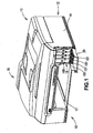
- Fig. 1 is a perspective view of a multi-function device, according to an embodiment of the present invention.
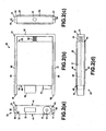
- Figs. 2(a)-2(d) are a front view, a side view, a rear view, and a bottom view, respectively, of an ink cartridge according to an embodiment of the present invention.
- Fig. 3(a) is a front view of a case of the ink cartridge of Figs. 2(a)-2(d) .
- Fig. 3(b) is a cross-sectional view of the case taken along the line IIIb-IIIb of Fig. 3(a) .
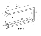
- Fig. 4 is a perspective view of a movable member of the ink cartridge of Figs. 2(a)-2(d) .
- Figs. 5(a) is a schematic depicting the ink cartridge of Figs. 2(a)-2(d) when colliding with a surface, in which a third plate portion of the movable member faces downward.
- Figs. 5(b) is another schematic depicting the ink cartridge of Figs. 2(a)-2(d) when colliding with a surface, in which the third plate portion of the movable member faces downward.
- Figs. 6(a) is a schematic depicting the ink cartridge of Figs. 2(a)-2(d) when colliding with a surface, in which a front face of the case faces downward.
- Figs. 6(b) is another schematic depicting the ink cartridge of Figs. 2(a)-2(d) when colliding with a surface, in which a front face of the case faces downward.
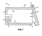
- Fig. 7 is a cross-sectional view of a cartridge accommodating case, according to an embodiment of the present invention.
- Fig. 8 is a cross-sectional view of the ink cartridge of Figs. 2(a)-2(d) mounted to the cartridge accommodating case of Fig. 7 , in which a lock lever is in an open position.
- Fig. 9 is a cross-sectional view of the ink cartridge of Figs. 2(a)-2(d) mounted to the cartridge accommodating case of Fig. 7 , in which a lock lever is in a closed position.
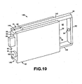
- Fig. 10 is a perspective view of an ink cartridge, according to another embodiment of the present invention.
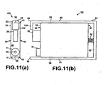
- Figs. 11 (a) and 11(b) are a front view and a side view, respectively, of an ink cartridge, according to yet another embodiment of the present invention.
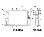
- Figs. 12(a) and 12(b) are a side view and a rear view, respectively, of an ink cartridge, according to still another embodiment of the present invention.
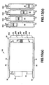
- Figs. 13(a) and 13(b) are a side view and a rear view, respectively, of the ink cartridges of Fig. 12(a) and 12(b) , in which four ink cartridges are positioned side by side.
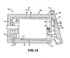
- Fig. 14 is a cross-sectional view of the ink cartridge of Figs. 12(a)-12(b) mounted to a cartridge accommodating case, in which a lock lever is in an open position.
- Fig. 15 is a cross-sectional view of the ink cartridge of Figs. 12(a)-12(b) mounted to the cartridge accommodating case, in which a lock lever is in a closed position.
- Multi-function device 10 configured to be used with an ink cartridge 30 according to an embodiment of the invention is depicted.
- Multi-function device 10 comprise s a printer portion 12 at the bottom and a scanner portion 13 at the top.
- Scanner portion 13 comprises an automatic sheet feeder 15.
- Multi-function device 10 is configured to be connected to a computer or another external device, e.g., a digital camera. When printing data is transmitted to printer portion 12 from the computer, the external device, or scanner portion 13, printer portion 12 prints an image on a sheet of paper based on the printing data.
- Multi-function device 10 has a substantially rectangular parallelepiped shape having a width, a depth, and a height. Each of the width and the depth is greater than the height.
- Printer portion 12 comprises a case 14, and case 14 has an opening 17 formed therethrough at a center of a front face of case 14.
- a tray (not shown) configured to accommodate sheets of paper is disposed in case 14, and the tray is configured to be removed from the interior of case 14 through opening 17.
- Case 14 also has an opening 18 formed therethrough at a position adjacent to an end of the front face of case 14 in the width direction of multi-function device 10.
- Multi-functional device 10 also comprises a cartridge accommodating portion 100 positioned in case 14, and cartridge accommodating portion 100 is exposed to the exterior of case 14 through opening 18.
- Cartridge accommodating portion 100 comprises a plurality of, e.g., four, cartridge accommodating cases 101, each of which is configured to accommodate an ink cartridge 30 therein.
- Each ink cartridge 30 stores ink therein, e.g., each ink cartridge 30 stores a different color of ink therein.
- a first ink cartridge 30 stores black ink therein
- a second ink cartridge 30 stores yellow ink therein
- a third ink cartridge 30 stores cyan ink therein
- a fourth ink cartridge stores magenta ink therein.
- the plurality of cartridge accommodating cases 101 are aligned in the width direction of multi-function device 10.
- Multi-function device 10 comprises a door 20, and the lower end of door 20 is coupled to case 14 below opening 18, such that door 20 is configured to pivot about the lower end of door 20.
- Door 20 is configured to expose cartridge accommodating portion 100 through opening 18 when door 20 is opened, and to cover opening 18 when door 20 is closed.
- ink cartridge 30 comprises a case 32, a movable member 33, and a resilient member, e.g., a coil spring 34.
- Case 32 and movable member 33 are coupled via coil spring 34, and movable member 33 is configured to move relative to case 32, e.g., to slide on case 32, when coil spring 34 expands in an expansion direction and contracts in a contraction direction which is opposite the expansion direction.
- a first end of coil spring 34 is coupled to case 32, and a second end of coil spring 34 is coupled to movable member 33.
- Coil spring 34 may be coupled to case 32 by direct contact or by indirect contact therebetween, and coil spring may be coupled to movable member 32 by direct contact or by indirect contact therebetween.
- coil spring 34 is indirectly connected to case 32, at least one element is positioned between coil spring 34 and case 32.
- coil spring 34 is indirectly connected to movable member 33, at least one element is positioned between coil spring 34 and movable member 33.
- Case 32 has a substantially rectangular parallelepiped shape having a front face 40, a rear face 42 opposite front face 40, a top face 41, a bottom face 43 opposite top face 41, and side faces 44 opposite each other.
- Each of top face 41 and bottom face 43 is connected to front face 40 and rear face 42
- each of side faces 44 is connected to front face 40, rear face 42, top face 41, and bottom face 43.
- Each of front face 40, top face 41, rear face 42, bottom face 43, and side faces 44 is substantially parallel to its opposing face, and substantially perpendicular to the other faces.
- Case 32 has a width from one of side faces 44 to the other of side faces 44, a depth from front face 40 to rear face 42, and a height from top face 41 to bottom face 43.
- Case 32 comprises an ink chamber 36 formed therein, and ink chamber 36 is configured to store ink.
- Case 32 comprises at least one translucent resin material, e.g., a transparent resin material or a semi-transparent resin material, which allows light to pass therethrough.
- a shape of case 32 in the expansion and contraction directions is not altered when coil spring 34 expands and contracts.
- the entire moveable member 33 is configured to substantially simultaneously move in a first direction relative to case 32 when coil spring 34 member expands, and the entire moveable member 33 is configured to substantially simultaneously move relative to case 32 in a second direction opposite the first direction when coil spring 34 contracts.
- Case 32 comprises a translucent portion 39, and rails 55 and 56 at top face 41 and bottom face 43, respectively.
- a pivotable member 60 is pivotally disposed within ink chamber 36.
- Translucent portion 39 is positioned at front face 40 and extends away from ink chamber 36.
- the translucent portion 39 is integral with case 32, and comprises the same material as frame 32.
- case 32 may comprise a frame which comprises front face 40, top face 41, rear face 42, and bottom face 43, and each of side faces 44 may comprise a film connected to, e.g., adhered to, the frame, such as by welding.
- Translucent portion 39 projects outward from a center portion of front face 40 of case 32 in a direction away from ink chamber 36.
- Translucent portion 39 is defined by five rectangular walls and has an inner space 46 formed therein which has a substantially a hollow box shape.
- translucent portion 39 is defined by a front wall, a pair of side walls, a top wall, and a bottom wall 47.
- the front wall extends parallel to front face 40 and is separated from front face 40 by a predetermined distance.
- the pair of side walls is connected to front face 40 and the front wall, the top wall is connected to the top ends of the front wall and the side walls, and bottom wall 47 is connected to bottom ends of the front wall and the side walls.
- the width of the front wall is less than the width of front face 40.
- Inner space 46 of translucent portion 39 is configured to be in fluid communication with ink chamber 36, e.g., there is no wall positioned between inner space 46 and ink chamber 36.
- An indicating portion 62 of the pivotable member 60 is configured to move within inner space 46, e.g., between a first position and a second position within inner space 46. For example, when indicating portion 62 is at the first position, indicating portion 62 contacts bottom wall 47 of translucent portion 39, as indicated by a solid line in Fig. 3(b) , and when indicating portion 62 is positioned at the second position, indicating portion 62 is separated form bottom wall 47 of translucent portion 39, as indicated by a dotted line in Fig. 3(b) .
- Pivotable member 60 is used to determine whether the amount of ink stored in the ink chamber 36 is greater than or equal to a sufficient amount of ink.
- Pivotable member 60 comprises indicating portion 62 at one end thereof, and a float portion 64 at the other end thereof.
- Pivotable member 60 also comprises a shaft 66 which is connected to indicating portion 62 and float portion 64. Shaft 66 extends in the width direction of case 32, and shaft 66 is supported by supporting portions disposed on inner surfaces of walls defining side faces 44, respectively, such that pivotable member 60 pivots about shaft 66 in directions indicated by arrows 67 and 68 in Fig. 3(b) .
- the specific gravity of float portion 64 is less than the specific gravity of ink stored in the ink chamber 36.
- Float portion 64 has a hollow formed therein, and floats on liquid, such that the float portion 64 moves upward and downward based on the amount of ink within the ink chamber 36, and pivotable member 60 pivots based on the movement of float portion 64.
- float portion 64 may be a solid element comprising a material having a specific gravity less than the specific gravity of ink.
- Indicating portion 62 is configured to indicate whether the amount of ink in the ink chamber 36 is greater than or equal to a sufficient amount of ink.
- indicating portion 62 contacts bottom wall 47 of translucent portion 39, such that further movement of pivotable member 60 is prevented and indicating portion 62 remains at the first position.
- indicating portion 62 moves away from bottom wall 47 of the translucent portion 39.
- float portion 64 contacts a bottom surface of the ink chamber 36, further movement of pivotable member 60 is prevented, and indicating portion 62 remains at the second position apart from bottom wall 47 of translucent portion 39 by a predetermined distance.
- Pivotable member 60 comprises a first portion extending from shaft 66 to indicating portion 62, and a second portion extending from shaft 66 to float portion 64.
- the mass of the first portion of pivotable member 60 is less than the mass of the second portion of pivotable member 60. Therefore, the second portion of pivotable member 60 is heavier than the first portion of pivotable member 60 in air. Accordingly, when the ink chamber 36 does not store a sufficient amount of ink therein, e.g., when the ink chamber 36 is empty of ink, pivotable member 60 pivots clockwise about shaft 66 in Fig. 3(b) , and indicating portion 62 separates from bottom wall 47 of detecting window 39.
- pivotable member 60 stops pivoting and the indicating portion 62 remains at the second position.
- indicator portion 62 it is determined that the amount of ink in ink chamber 36 is less than a sufficient amount of ink.
- whether the amount of ink in ink chamber 36 is greater than or equal to the predetermined amount of ink is determined based on the position of indicating portion 62 in the inner space 46, e.g., the position of indicating portion 62 is detected by a photo interrupter or viewed by a user.
- Front face 40 has an opening 52 formed therethrough adjacent to an end of front face 40 connected to bottom face 43, and the interior of ink chamber 36 is configured to be in fluid communication with the exterior of case 32 via opening 52.
- Ink cartridge 30 comprises an ink supply portion 51 positioned at front face 40 of case 32 adjacent to the end of front face 40 connected to bottom face 43.
- Ink supply portion 51 comprises a cylindrical rubber member having an inner hole 53 formed therethrough.
- the cylindrical rubber member comprises a first portion and a second portion. The first portion of the cylindrical rubber member is press fitted in opening 52, and the second portion of the cylindrical rubber member extends outward from front face 40. Opening 52 and inner hole 53 are aligned, such that the interior of ink chamber 36 is configured to be in fluid communication with the exterior of case 32 via opening 52 and inner hole 53.
- a film (not shown) is positioned on an end of the cylindrical rubber member to cover inner hole 53.
- a connecting portion 111 is connected to ink supply portion 51, such that a needle (not shown) of connecting portion 111 penetrates through the film and enters inner hole 53. Then, ink is supplied from ink chamber 36 to a recording head (not shown) of multi-function device 10 via ink supply portion 51 and connecting portion 111.
- An air intake hole 50 is formed through front face 40, and the interior of ink chamber 36 is configured to be in fluid communication with the exterior of case 32 via air intake hole 50.
- a sticker (not shown) covers the air intake hole 50, and the sticker prevents fluid communication between the interior of the ink chamber 36 and the exterior of case 32 via air intake hole 50.
- the user removes the sticker, and thereby ink chamber 36 is brought into fluid communication with the exterior of case 32 via air intake hole 50.
- Case 32 comprises a spring seat 48 formed on and extending outwardly from rear face 42 at a middle portion of rear face 42 in the height direction of case 32.
- An end of coil spring 34 is connected and fixed to spring seat 48.
- Rail 55 extends outwardly from top face 41 and extends from a portion adjacent to front face 40 to a portion adjacent to rear face 42 in the depth direction of case 32.
- the depth direction of case 32 is indicated by an arrow 69 in Fig. 3(b) .
- Rail 56 extends outwardly from bottom face 43 and extends from a portion adjacent to front face 40 to a portion adjacent to rear face 42 in the depth direction of case 32.
- movable member 33 is configured to support case 32, such that movable member 33 moves relative to case 32, e.g., slides on case 32 when coil spring 34 expands and contracts.
- Movable member 33 comprises a first plate portion 90, a second plate portion 91 opposite first plate portion 90, and a third plate portion 92 connected to first plate portion 90 and second plate portion 91.
- First plate portion 90 and second plate portion 91 are parallel to each other, and third plate portion 92 is perpendicular to each of first plate portion 90 and second plate portion 91.
- first plate portion 90 and second plate portion 91 has a first end 96 and a second end opposite first end 96
- third plate portion 92 has a first end and a second end opposite the first end.
- the first end of third plate potion 92 is connected to the second end of first plate portion 90
- the second end of third plate portion 92 is connected to the second end of the second plate portion 91.
- Case 32 is surrounded by first plate portion 90, second plate portion 91, and third plate portion 92.
- First plate portion 90 faces top face 41
- second plate portion 91 faces bottom face 43
- third plate portion 92 faces rear face 42.
- First plate potion 90 has a first groove 88 formed in the surface facing top face 41, and first groove 88 extends from first end 96 of first plate portion 90 towards the second end of first plate portion 90.
- First plate portion 90 engages top face 41, e.g., first groove 88 extends parallel to rail 55, and rail 55 is positioned within first groove 88.
- Second plate potion 91 has a second groove 89 formed in the surface facing bottom face 43, and second groove 89 extends from first end 96 of second plate portion 91 towards the second end of second plate portion 91.
- Second plate portion 91 engages bottom face 43, e.g., second groove 89 extends parallel to rail 56, and rail 56 is positioned within second groove 89.
- first groove 88 and second groove 89 has a wide portion 97 adjacent to first end 96, and the width of wide portion 97 increases as wide portion 97 approaches first end 96.
- rails 55 and 56 readily slide in first groove 88 and second groove 89 with the aid of wide portions 97.
- Third plate portion 92 comprises a spring seat 94 formed on and extending outwardly from the surface facing rear face 42 at a middle portion of third plate portion 92 in the height direction of case 32.
- An end of coil spring 34 is connected and fixed to spring seat 94.
- first plate portion 90 and second plate portion 91 extends adjacent to and away from front face 40 in the second direction in which translucent portion 39 and ink supply portion 51 extends outwardly from front face 40.
- Each of first plate portion 90 and second plate portion 91 extends further outwardly from front face 40 than translucent portion 39 and ink supply portion 51 extends from front face 40 in the second direction, independent of whether coil spring 34 is in an expanded or contracted position.
- first plate portion 90 or second plate portion 91 may be omitted.
- ink cartridge 30 is manufactured, as follows. An end of coil spring 34 is connected and fixed to spring seat 94 of third plate portion 94. Case 32 is then inserted from rear face 42 side into a space 87 which is surrounded by first plate portion 90, second plate portion 91, and third plate portion 92. Rails 55 and 56 is then inserted into first and second grooves 88 and 89, respectively, via wide portions 97. After that, the other end of coil spring 34 is connected and fixed to spring seat 48 of case 32. The direction in which movable member 33 and case 32 slides relative to each other is parallel to the direction in which coil spring 34 expands and contracts.
- ink cartridge 30 when ink cartridge 30 is transferred, e.g., during shipment of ink cartridge 30 from a factory, ink cartridge 30 may vibrate. Nevertheless, the vibration may not be transferred to case 32 because coil spring 34 absorbs the vibration. Consequently, the vibration may not generate air bubbles in ink chamber 36.
- first end 96 of first plate portion 90 or first end 96 of second plate portion 91, or both contacts the surface 23, and at least a portion of the impact of the collision is absorbed by coil spring 34. Consequently, case 32 is protected from the impact, and case 32 may not be damaged by the impact.
- first plate portion 90 and second plate portion 91 extends further outwardly from front face 40 than translucent portion 39 and ink supply portion 51 extends from front face 40, ink supply portion 51 and translucent portion 39 do not contact surface 23. Consequently, the impact is not directly transferred to ink supply portion 51 or translucent portion 39, or both, which prevents ink supply portion 51 and translucent portion 39 from being damaged.
- cartridge accommodating case 101 comprises a case main body 105 and a lock lever 106.
- Case main body 105 comprises an accommodating chamber 108 formed therein.
- Case main body 105 has an opening 110 formed therethrough, which is positioned adjacent to opening 18 of case 14 of printer portion 12.
- Ink cartridge 30 is selectively installed in and removed from accommodating chamber 108 via opening 110.
- Case main body 105 has a wall 114 defining an end of accommodating chamber 108 opposite from opening 110, and an optical sensor 103 is provided at wall 114.
- Optical sensor 103 is a photo interrupter comprising a light emitting portion and a light receiving portion.
- translucent portion 39 is positioned between the light emitting portion and the light receiving portion.
- the intensity of light received by the light receiving portion varies. Based on the intensity of light received by the light receiving portion, it is determined whether the amount of ink in ink cartridge 30 is greater than or equal to a sufficient amount of ink.
- a connecting portion 111 is provided at wall 114 below optical sensor 103. Connecting portion 111 extends from wall 144 towards the interior of accommodating chamber 108. When ink cartridge 30 is installed in accommodating chamber 108, connecting portion 111 is connected to ink supply portion 51, such that a needle (not shown) provided at connecting portion 111 penetrates through the film (not shown) of ink supply portion 51 and enters inner hole 53. Connecting portion 111 has a through hole 124 formed therethrough, and one end of through hole 14 is connected to the needle and the other end of through hole 14 is connected to a flexible tube (not shown) which is connected to a recording head (not shown).
- Case main body 105 comprises a bottom wall 117, and a space 113 is formed between bottom wall 117 and connecting portion 111.
- first end 96 of second plate portion 91 is positioned within space 113.
- lock lever 106 is coupled to case main body 105 above opening 110, such that lock lever 106 pivots about the upper end of lock lever 106.
- Lock lever 106 is configured to expose accommodating chamber 108 through opening 110 when lock lever 106 is opened, and to cover opening 110 when lock lever 106 is closed.
- Lock lever 106 comprises a pressing portion 125 and a claw 126. Pressing portion 125 extends from a middle portion of an inner surface 129 of lock lever 106.
- Claw 126 is positioned at the lower end of lock lever 106.
- Bottom wall 117 has a cut-out 127 formed in the outer surface of bottom wall 117 below opening 110, and claw 126 is configured to engage cut-out 127.
- Ink cartridge 30 is inserted into accommodating chamber 108 until ink supply portion 51 contacts connecting portion 111, translucent portion 39 enters between the light emitting portion and the light receiving portion of optical sensor 103, and first end 96 of second plate portion 91 enters space 113.
- Lock lever 106 is then pivoted towards the case main body 105 until pressing portion 125 contacts third plate potion 92.
- coil spring 34 contracts and movable member 33 moves towards wall 114, while case 32 remains stationary.
- claw 126 engages cut-out 127, and lock lever 160 is completely closed and is fixed to case main body 105.
- Lock lever 106 retains ink cartridge 30 in case main body 105 and ink supply portion 51 is pressed against connecting portion 111 by coil spring 34.
- ink cartage 30 is installed in cartridge accommodating case 101 securely. Moreover, ink cartridge 30 is pressed in an installation direction as indicated by an arrow 70 in Figs. 8 and 9 with a constant force depending on the elasticity of coil spring 34. Furthermore, because ink supply portion 51 is pressed against connecting portion 111 tightly, ink is prevented from leaking between ink supply portion 51 and connecting portion 111.
- case 32 in the expansion and contraction directions were altered when coil spring 34 expands and contracts, the shape of case 32 might be deformed when ink is consumed from ink chamber 36, and coil spring 34 might be fully expanded when ink stored in the ink chamber 36 is almost used up.
- coil spring 34 when the user disengages claw 126 from cut-out 127, coil spring 34 might not expand further, which might not cause movable member 33 to push up lock lever 106 and not cause ink cartridge 30 to be partially ejected from case main body 105.
- the shape of case 32 in the expansion and contraction directions is not be altered when coil spring 34 expands and contracts. Therefore, ink cartridge 30 is readily removed from cartridge accommodating case 101.
- the entire moveable member 33 is configured to substantially simultaneously move in a first direction relative to case 32 when coil spring 34 member expands, and the entire moveable member 33 is configured to substantially simultaneously move relative to case 32 in a second direction opposite the first direction when coil spring 34 contracts. Therefore, the impact of the collision is sufficiently absorbed by coil spring 34. If the entire moveable member 33 were not configured to substantially simultaneously move relative to case 32, the impact of the collision might not be absorbed by coil spring 34 sufficiently. In particular, if some portion of the movable member 33 were stationary relative to case 32 and attached to case 32, such a portion might be damaged by the impact.
- movable member 33 comprises a first plate portion 142 and a second plate portion 143 instead of first plate portion 90 and second plate portion 91.
- a cross-sectional shape of each of first plate portion 142 and second plate portion 143 is trapezoidal.
- the upper base of the trapezoidal cross sectional-shape of first plate portion 142 is shorter than the lower base of the trapezoidal cross-sectional shape of first plate portion 142.
- the upper base of the trapezoidal cross-sectional shape of second plate portion 143 is longer than the lower base of the trapezoidal cross-sectional shape of second plate portion 143.
- Case 32 does not comprise rails 55 and 56, but comprises a groove 144 and a groove 145 formed in top face 41 and bottom face 43, respectively.
- Groove 144 extends from the corner of top face 41 and front face 40 to the corner of top face 41 and rear face 42 in the depth direction of case 32
- groove 145 extends from the corner of bottom face 43 and front face 40 to the corner of bottom face 43 and rear face 42 in the depth direction of case 32.
- a cross-sectional shape of each of groove 144 and groove 145 is trapezoidal. The upper base of the trapezoidal cross-sectional shape of groove 144 is shorter than the lower base of the trapezoidal cross-sectional shape of groove 144.
- the upper base of the trapezoidal-cross sectional shape of groove 145 is longer than the lower base of the trapezoidal-cross sectional shape of groove 145.
- First plate portion 142 and second plate portion 143 are inserted into groove 144 and groove 145, respectively, such that first plate portion 142 and second plate portion 143 slides in groove 144 and groove 145, respectively. Because of the trapezoidal cross-sectional shape of first plate portion 142, second plate portion 143, groove 144, and groove 145, case 32 and movable member 30 are coupled securely, and ink cartridge 140 may be disassembled only when movable member 30 slides off case 32 in the depth direction of case 32.
- movable member 33 further comprises a fourth plate portion 152 extending from first end 96 of first plate portion 90 downwardly and substantially perpendicular to first plate portion 90.
- the lower end of fourth plate portion 152 is positioned above and adjacent to translucent portion 39.
- Fourth plate portion 152 may be manufactured separately from movable member 33, and may be attached to movable member 33 via ultrasonic welding.
- fourth plate portion 152 When ink cartridge 150 contacts a surface with front face 40 facing downward, front face 40 is protected by fourth plate portion 152.
- fourth plate portion 152 For example, when ink cartridge 150 contacts a surface with an amount of force greater than a predetermined amount of force, and coil spring 32 expands too much, the sliding motion of case 32 to the front face 40 side is restricted by forth plate portion 152.
- movable member 33 further comprises a grasping portion 162 formed on and extending from the outer surface of third plate portion 92.
- Ink cartridge 160 is configured to be installed in a cartridge accommodating case 165.
- the user grasps grasping portion 162.
- the position of grasping portion 162 depends on the color of ink stored in ink cartridge 160. Referring to Fig. 13 , a grasping portion 162K of an ink cartridge 160K storing black ink is positioned adjacent to the upper end of third plate portion 92, a grasping portion 162C of an ink cartridge 160C storing cyan ink is positioned below grasping portion 162K of ink cartridge 160K, a grasping portion 162Y of an ink cartridge 160Y storing yellow ink is positioned below grasping portion 162C of ink cartridge 160C, and a grasping portion 162M of an ink cartridge 160M storing magenta ink is positioned adjacent to the lower end of third plate portion 92 and below grasping portion 162Y of ink cartridge 160Y.
- grasping portions 162K, 162C, 162Y, and 162M are offset in the height direction of case 32. Therefore, a user readily grasps grasping portions 162K, 162C, 162Y, and 162M without interference from adjacent grasping portions 162K, 162C, 162Y, and 162M.
- lock lever 106 comprises a recess 167 formed in inner surface 129 of lock lever 106 instead of pressing portion 125.
- grasping portion 162 is accommodated in recess 167.
- the shape and the position of recess 167 corresponds to the shape and the position of grasping portion 162.
- the position of recess 167 depends on the color of ink which is stored in the installed ink cartridge 160.
- Ink cartridge 160 is inserted into accommodating chamber 108 until ink supply portion 51 contacts connecting portion 111.
- Lock lever 106 is then pivoted towards the case main body 105, grasping portion 162 enters recess 167, and an end 163 of grasping portion 162 contacts a bottom 168 of recess 167.
- coil spring 34 contracts and movable member 33 moves towards wall 114, and case 32 remains stationary.
- claw 126 engages cut-out 127, and lock lever 160 is completely closed and fixed to case main body 105.
- recess 167 depends on the color of ink which the installed ink cartridge 160 stores therein, if ink cartridge 160K is inadvertently installed in cartridge accommodating case 165 configured to accommodate ink cartridge 160C, recess 167 does not accommodate grasping portion 162K. Consequently, a user readily notices that the user installed the ink cartridge in a wrong one of cartridge accommodating cases 165.
Abstract
Description
- The present invention relates generally to ink cartridges. In particular, the present invention is related to ink cartridges which are configured to dispense ink when mounted in a printer.
- A known ink cartridge is configured to be mounted to a mounting portion of a known recording apparatus, such as an ink-jet recording apparatus. The known ink cartridge has an ink chamber configured to store ink therein, a wall defining at least a portion of the ink chamber, and an ink supply portion positioned at the wall, which is configured to supply ink from the interior of the ink chamber to the exterior of the ink chamber. The ink supply portion extends outwardly from the wall. A resilient member is disposed within the ink supply portion. When the known ink cartridge is dropped and collides with a surface, such as a floor, a portion of the impact of the collision may be absorbed by the resilient member. Such a known ink cartridge is described in
JP-A-2001-71522 - Nevertheless, because the resilient member is disposed within the ink supply portion, an outer portion of the ink supply portion may be damaged when the ink supply portion contacts the surface, which may cause ink to leak from the ink supply portion. Moreover, if the ink cartridge contacts the surface at a position other than the ink supply portion, the ink cartridge may be damaged, and ink may leak from the ink cartridge.
- Another known ink cartridge is configured to be mounted to an accommodating chamber of the known recording apparatus, and the accommodating chamber includes a door which is configured to be opened and closed. After the known ink cartridge is mounted to the accommodating chamber and the door is closed, the door may latch on to the ink cartridge to remove the ink cartridge from the accommodating chamber when the door is opened by a user, which increases the.ease with which the ink cartridge may be removed from the accommodating chamber. Such a known ink cartridge is described in
US 2007/0070140 A1 for example. Nevertheless, the user relies on the recording apparatus to remove the ink cartridge from the recording apparatus. - From
US 2006/0087532 A1 an apparatus for ejecting droplets is known which is provided with an ejecting head for discharging droplets, and electric circuit board having an electric circuit formed on a surface of the electric circuit board, the electric circuit being connected to the ejecting head, a holder for supporting the ejecting head and the electric circuit board, and a cover that overlaps the surface of the electric board when the cover is fixed to the holder. The apparatus for ejecting droplets is further provided with a seal member that fills a gap formed between a peripheral region of the surface of the electric circuit board and an inner surface of the cover. The seal member effectively prevents droplets missed from penetrating to the electric circuit. - Therefore, a need has arisen for ink cartridges which overcome these and other shortcomings of the related art. A technical advantage of the present invention is that the ink cartridge may be protected from damage when the ink cartridge contacts the surface. Another technical advantage of the present invention is that the ink cartridge may be readily removed from the recording apparatus.
- According to an embodiment of the present invention an ink cartridge according to claim 1 is provided.
- With this configuration, ink cartridge is protected from damage when the ink cartridge contacts a surface. Moreover, ink cartridge is readily removed from a recording apparatus.
- At least one portion of the movable member may extend adjacent to and away from the front face of the case in the second direction. Moreover, the ink supply portion may extend from the front face of the case in the second direction, and the at one portion of the movable member may extend further from the front face of the case in the second direction than the ink supply portion extends from the front face of the case in the second direction. With this configuration, ink supply portion may not contact the surface and may be protected from the damage.
- The ink cartridge may further comprise a translucent portion positioned at the front face of the case and extending away from the ink chamber, and the translucent portion may have an inner space formed therein, and the inner space may be configured to be in fluid communication with the ink chamber. The ink cartridge also may comprise a further movable member positioned within the inner space, and the further movable member may be configured to move within the inner space based on an amount of ink in the ink chamber. Moreover, each of the ink supply portion and the translucent portion may extend from the front face of the case in the second direction, and the at least one portion of the movable member may extend further from the front face of the case in the second direction than each of the ink supply portion and the translucent portion extends from the front face of the case in the second direction. With this configuration, each of the ink supply portion and the translucent portion may not contact the surface and may be protected from the damage.
- Moreover, the ink supply portion may extend from the front face of the case in the second direction, and the second portion of the movable member may extend further from the front face of the case in the second direction than the ink supply portion extends from the front face of the case in the second direction. With this configuration, ink supply portion may not contact the surface and may be protected from the damage.
- The case may further comprise a further face opposite the particular face and connected to each of the front face and the rear face. The movable member may comprise a third portion extending from the first portion in the second direction. The third portion of the movable member may engage the further face and extend away from the front face in the second direction. The ink supply portion may extend from the front face of the case in the second direction, and each of the second portion and the third portion of the movable member may extend further from the front face of the case in the second direction than the ink supply portion extends from the front face of the case in the second direction. With this configuration, ink supply portion may not contact the surface and may be protected from the damage.
- Other objects, features, and advantages of embodiments of the present invention will be apparent to persons of ordinary skill in the art from the following description of preferred embodiments with reference to the accompanying drawings.
- For a more complete understanding of the present invention, the needs satisfied thereby, and the objects, features, and advantages thereof, reference now is made to the following description taken in connection with the accompanying drawings.
-
Fig. 1 is a perspective view of a multi-function device, according to an embodiment of the present invention. -
Figs. 2(a)-2(d) are a front view, a side view, a rear view, and a bottom view, respectively, of an ink cartridge according to an embodiment of the present invention. -
Fig. 3(a) is a front view of a case of the ink cartridge ofFigs. 2(a)-2(d) . -
Fig. 3(b) is a cross-sectional view of the case taken along the line IIIb-IIIb ofFig. 3(a) . -
Fig. 4 is a perspective view of a movable member of the ink cartridge ofFigs. 2(a)-2(d) . -
Figs. 5(a) is a schematic depicting the ink cartridge ofFigs. 2(a)-2(d) when colliding with a surface, in which a third plate portion of the movable member faces downward. -
Figs. 5(b) is another schematic depicting the ink cartridge ofFigs. 2(a)-2(d) when colliding with a surface, in which the third plate portion of the movable member faces downward. -
Figs. 6(a) is a schematic depicting the ink cartridge ofFigs. 2(a)-2(d) when colliding with a surface, in which a front face of the case faces downward. -
Figs. 6(b) is another schematic depicting the ink cartridge ofFigs. 2(a)-2(d) when colliding with a surface, in which a front face of the case faces downward. -
Fig. 7 is a cross-sectional view of a cartridge accommodating case, according to an embodiment of the present invention. -
Fig. 8 is a cross-sectional view of the ink cartridge ofFigs. 2(a)-2(d) mounted to the cartridge accommodating case ofFig. 7 , in which a lock lever is in an open position. -
Fig. 9 is a cross-sectional view of the ink cartridge ofFigs. 2(a)-2(d) mounted to the cartridge accommodating case ofFig. 7 , in which a lock lever is in a closed position. -
Fig. 10 is a perspective view of an ink cartridge, according to another embodiment of the present invention. -
Figs. 11 (a) and 11(b) are a front view and a side view, respectively, of an ink cartridge, according to yet another embodiment of the present invention. -
Figs. 12(a) and 12(b) are a side view and a rear view, respectively, of an ink cartridge, according to still another embodiment of the present invention. -
Figs. 13(a) and 13(b) are a side view and a rear view, respectively, of the ink cartridges ofFig. 12(a) and 12(b) , in which four ink cartridges are positioned side by side. -
Fig. 14 is a cross-sectional view of the ink cartridge ofFigs. 12(a)-12(b) mounted to a cartridge accommodating case, in which a lock lever is in an open position. -
Fig. 15 is a cross-sectional view of the ink cartridge ofFigs. 12(a)-12(b) mounted to the cartridge accommodating case, in which a lock lever is in a closed position. - Embodiments of the present invention and their features and technical advantages may be understood by referring to
Figs. 1-15 , like numerals being used for like corresponding portions in the various drawings. - Referring to
Fig. 1 amulti-function device 10 configured to be used with anink cartridge 30 according to an embodiment of the invention is depicted.Multi-function device 10 comprise s a printer portion 12 at the bottom and ascanner portion 13 at the top.Scanner portion 13 comprises anautomatic sheet feeder 15.Multi-function device 10 is configured to be connected to a computer or another external device, e.g., a digital camera. When printing data is transmitted to printer portion 12 from the computer, the external device, orscanner portion 13, printer portion 12 prints an image on a sheet of paper based on the printing data. -
Multi-function device 10 has a substantially rectangular parallelepiped shape having a width, a depth, and a height. Each of the width and the depth is greater than the height. Printer portion 12 comprises acase 14, andcase 14 has anopening 17 formed therethrough at a center of a front face ofcase 14. A tray (not shown) configured to accommodate sheets of paper is disposed incase 14, and the tray is configured to be removed from the interior ofcase 14 throughopening 17.Case 14 also has anopening 18 formed therethrough at a position adjacent to an end of the front face ofcase 14 in the width direction ofmulti-function device 10.Multi-functional device 10 also comprises acartridge accommodating portion 100 positioned incase 14, andcartridge accommodating portion 100 is exposed to the exterior ofcase 14 throughopening 18.Cartridge accommodating portion 100 comprises a plurality of, e.g., four,cartridge accommodating cases 101, each of which is configured to accommodate anink cartridge 30 therein. Eachink cartridge 30 stores ink therein, e.g., eachink cartridge 30 stores a different color of ink therein. For example, afirst ink cartridge 30 stores black ink therein, asecond ink cartridge 30 stores yellow ink therein, athird ink cartridge 30 stores cyan ink therein, and a fourth ink cartridge stores magenta ink therein. The plurality of cartridgeaccommodating cases 101 are aligned in the width direction ofmulti-function device 10. -
Multi-function device 10 comprises adoor 20, and the lower end ofdoor 20 is coupled tocase 14 below opening 18, such thatdoor 20 is configured to pivot about the lower end ofdoor 20.Door 20 is configured to exposecartridge accommodating portion 100 throughopening 18 whendoor 20 is opened, and to coveropening 18 whendoor 20 is closed. - Referring to
Figs. 2-4 ,ink cartridge 30 comprises acase 32, amovable member 33, and a resilient member, e.g., acoil spring 34.Case 32 andmovable member 33 are coupled viacoil spring 34, andmovable member 33 is configured to move relative tocase 32, e.g., to slide oncase 32, whencoil spring 34 expands in an expansion direction and contracts in a contraction direction which is opposite the expansion direction. For example, a first end ofcoil spring 34 is coupled tocase 32, and a second end ofcoil spring 34 is coupled tomovable member 33.Coil spring 34 may be coupled tocase 32 by direct contact or by indirect contact therebetween, and coil spring may be coupled tomovable member 32 by direct contact or by indirect contact therebetween. Whencoil spring 34 is indirectly connected tocase 32, at least one element is positioned betweencoil spring 34 andcase 32. Similarly, whencoil spring 34 is indirectly connected tomovable member 33, at least one element is positioned betweencoil spring 34 andmovable member 33. -
Case 32 has a substantially rectangular parallelepiped shape having afront face 40, arear face 42 oppositefront face 40, atop face 41, abottom face 43 oppositetop face 41, and side faces 44 opposite each other. Each oftop face 41 andbottom face 43 is connected tofront face 40 andrear face 42, and each of side faces 44 is connected tofront face 40,rear face 42,top face 41, andbottom face 43. Each offront face 40,top face 41,rear face 42,bottom face 43, and side faces 44 is substantially parallel to its opposing face, and substantially perpendicular to the other faces.Case 32 has a width from one of side faces 44 to the other of side faces 44, a depth fromfront face 40 torear face 42, and a height fromtop face 41 tobottom face 43. The height ofcase 32 is greater than the width ofcase 32, and the depth ofcase 32 is greater than the height ofcase 32.Case 32 comprises anink chamber 36 formed therein, andink chamber 36 is configured to store ink.Case 32 comprises at least one translucent resin material, e.g., a transparent resin material or a semi-transparent resin material, which allows light to pass therethrough. - In an embodiment, a shape of
case 32 in the expansion and contraction directions is not altered whencoil spring 34 expands and contracts. The entiremoveable member 33 is configured to substantially simultaneously move in a first direction relative tocase 32 whencoil spring 34 member expands, and the entiremoveable member 33 is configured to substantially simultaneously move relative tocase 32 in a second direction opposite the first direction whencoil spring 34 contracts. -
Case 32 comprises atranslucent portion 39, and rails 55 and 56 attop face 41 andbottom face 43, respectively. A pivotable member 60 is pivotally disposed withinink chamber 36.Translucent portion 39 is positioned atfront face 40 and extends away fromink chamber 36. Thetranslucent portion 39 is integral withcase 32, and comprises the same material asframe 32. Whenink cartridge 30 is installed inmulti-function device 10,translucent portion 39 is irradiated with light emitted from asensor 103 ofmulti-function device 10. - In an embodiment, those portions of
case 32 other thantranslucent portion 39 may be covered with an opaque member to avoid the deterioration of ink disposed inink chamber 36 due to exposure to ultraviolet radiation. In another embodiment,case 32 may comprise a frame which comprisesfront face 40,top face 41,rear face 42, andbottom face 43, and each of side faces 44 may comprise a film connected to, e.g., adhered to, the frame, such as by welding. -
Translucent portion 39 projects outward from a center portion offront face 40 ofcase 32 in a direction away fromink chamber 36.Translucent portion 39 is defined by five rectangular walls and has aninner space 46 formed therein which has a substantially a hollow box shape. For example,translucent portion 39 is defined by a front wall, a pair of side walls, a top wall, and abottom wall 47. The front wall extends parallel tofront face 40 and is separated fromfront face 40 by a predetermined distance. The pair of side walls is connected tofront face 40 and the front wall, the top wall is connected to the top ends of the front wall and the side walls, andbottom wall 47 is connected to bottom ends of the front wall and the side walls. Moreover, the width of the front wall is less than the width offront face 40. -
Inner space 46 oftranslucent portion 39 is configured to be in fluid communication withink chamber 36, e.g., there is no wall positioned betweeninner space 46 andink chamber 36. An indicatingportion 62 of the pivotable member 60 is configured to move withininner space 46, e.g., between a first position and a second position withininner space 46. For example, when indicatingportion 62 is at the first position, indicatingportion 62contacts bottom wall 47 oftranslucent portion 39, as indicated by a solid line inFig. 3(b) , and when indicatingportion 62 is positioned at the second position, indicatingportion 62 is separated formbottom wall 47 oftranslucent portion 39, as indicated by a dotted line inFig. 3(b) . - Pivotable member 60 is used to determine whether the amount of ink stored in the
ink chamber 36 is greater than or equal to a sufficient amount of ink. Pivotable member 60 comprises indicatingportion 62 at one end thereof, and a float portion 64 at the other end thereof. Pivotable member 60 also comprises ashaft 66 which is connected to indicatingportion 62 and float portion 64.Shaft 66 extends in the width direction ofcase 32, andshaft 66 is supported by supporting portions disposed on inner surfaces of walls defining side faces 44, respectively, such that pivotable member 60 pivots aboutshaft 66 in directions indicated byarrows Fig. 3(b) . - The specific gravity of float portion 64 is less than the specific gravity of ink stored in the
ink chamber 36. Float portion 64 has a hollow formed therein, and floats on liquid, such that the float portion 64 moves upward and downward based on the amount of ink within theink chamber 36, and pivotable member 60 pivots based on the movement of float portion 64. Alternatively, float portion 64 may be a solid element comprising a material having a specific gravity less than the specific gravity of ink. - Indicating
portion 62 is configured to indicate whether the amount of ink in theink chamber 36 is greater than or equal to a sufficient amount of ink. When pivotable member 60 pivots counterclockwise inFig. 3(b) , indicatingportion 62contacts bottom wall 47 oftranslucent portion 39, such that further movement of pivotable member 60 is prevented and indicatingportion 62 remains at the first position. When pivotable member 60 pivots clockwise inFig. 3(b) , indicatingportion 62 moves away frombottom wall 47 of thetranslucent portion 39. When float portion 64 contacts a bottom surface of theink chamber 36, further movement of pivotable member 60 is prevented, and indicatingportion 62 remains at the second position apart frombottom wall 47 oftranslucent portion 39 by a predetermined distance. - Pivotable member 60 comprises a first portion extending from
shaft 66 to indicatingportion 62, and a second portion extending fromshaft 66 to float portion 64. The mass of the first portion of pivotable member 60 is less than the mass of the second portion of pivotable member 60. Therefore, the second portion of pivotable member 60 is heavier than the first portion of pivotable member 60 in air. Accordingly, when theink chamber 36 does not store a sufficient amount of ink therein, e.g., when theink chamber 36 is empty of ink, pivotable member 60 pivots clockwise aboutshaft 66 inFig. 3(b) , and indicatingportion 62 separates frombottom wall 47 of detectingwindow 39. When the lower end of float portion 64 contacts the bottom surface ofink chamber 36, pivotable member 60 stops pivoting and the indicatingportion 62 remains at the second position. Whenindicator portion 62 is at the second position, it is determined that the amount of ink inink chamber 36 is less than a sufficient amount of ink. - In contrast, when the amount of ink in
ink chamber 36 is greater than or equal to a sufficient amount of ink, and float portion 64 is submerged in the ink, a buoyancy force acts on float portion 64. The buoyancy force causes the pivotable member 60 to pivot counterclockwise aboutshaft 66 inFig. 3(b) . When pivotable member 60 pivots counterclockwise, indicatingportion 62contacts bottom wall 47 oftranslucent portion 39, and pivotable member 60 stops pivoting and indicatingportion 62 remains at the first position. When indicatingportion 62 is at the first position, it is determined that the amount of ink inink chamber 36 is greater than or equal to a sufficient amount of ink. - Specifically, whether the amount of ink in
ink chamber 36 is greater than or equal to the predetermined amount of ink is determined based on the position of indicatingportion 62 in theinner space 46, e.g., the position of indicatingportion 62 is detected by a photo interrupter or viewed by a user. -
Front face 40 has anopening 52 formed therethrough adjacent to an end offront face 40 connected tobottom face 43, and the interior ofink chamber 36 is configured to be in fluid communication with the exterior ofcase 32 viaopening 52.Ink cartridge 30 comprises anink supply portion 51 positioned atfront face 40 ofcase 32 adjacent to the end offront face 40 connected tobottom face 43.Ink supply portion 51 comprises a cylindrical rubber member having aninner hole 53 formed therethrough. The cylindrical rubber member comprises a first portion and a second portion. The first portion of the cylindrical rubber member is press fitted in opening 52, and the second portion of the cylindrical rubber member extends outward fromfront face 40.Opening 52 andinner hole 53 are aligned, such that the interior ofink chamber 36 is configured to be in fluid communication with the exterior ofcase 32 viaopening 52 andinner hole 53. A film (not shown) is positioned on an end of the cylindrical rubber member to coverinner hole 53. Whenink cartridge 30 is installed in cartridgeaccommodating case 101, a connectingportion 111 is connected toink supply portion 51, such that a needle (not shown) of connectingportion 111 penetrates through the film and entersinner hole 53. Then, ink is supplied fromink chamber 36 to a recording head (not shown) ofmulti-function device 10 viaink supply portion 51 and connectingportion 111. - An
air intake hole 50 is formed throughfront face 40, and the interior ofink chamber 36 is configured to be in fluid communication with the exterior ofcase 32 viaair intake hole 50. Beforeink cartridge 30 is used, a sticker (not shown) covers theair intake hole 50, and the sticker prevents fluid communication between the interior of theink chamber 36 and the exterior ofcase 32 viaair intake hole 50. When a user intends to useink cartridge 30, the user removes the sticker, and therebyink chamber 36 is brought into fluid communication with the exterior ofcase 32 viaair intake hole 50. -
Case 32 comprises aspring seat 48 formed on and extending outwardly fromrear face 42 at a middle portion ofrear face 42 in the height direction ofcase 32. An end ofcoil spring 34 is connected and fixed to springseat 48. -
Rail 55 extends outwardly fromtop face 41 and extends from a portion adjacent tofront face 40 to a portion adjacent torear face 42 in the depth direction ofcase 32. The depth direction ofcase 32 is indicated by anarrow 69 inFig. 3(b) .Rail 56 extends outwardly frombottom face 43 and extends from a portion adjacent tofront face 40 to a portion adjacent torear face 42 in the depth direction ofcase 32. - Referring to
Figs. 2 and4 ,movable member 33 is configured to supportcase 32, such thatmovable member 33 moves relative tocase 32, e.g., slides oncase 32 whencoil spring 34 expands and contracts.Movable member 33 comprises afirst plate portion 90, asecond plate portion 91 oppositefirst plate portion 90, and athird plate portion 92 connected tofirst plate portion 90 andsecond plate portion 91.First plate portion 90 andsecond plate portion 91 are parallel to each other, andthird plate portion 92 is perpendicular to each offirst plate portion 90 andsecond plate portion 91. Each offirst plate portion 90 andsecond plate portion 91 has afirst end 96 and a second end oppositefirst end 96, andthird plate portion 92 has a first end and a second end opposite the first end. The first end ofthird plate potion 92 is connected to the second end offirst plate portion 90, and the second end ofthird plate portion 92 is connected to the second end of thesecond plate portion 91.Case 32 is surrounded byfirst plate portion 90,second plate portion 91, andthird plate portion 92.First plate portion 90 facestop face 41,second plate portion 91 facesbottom face 43, andthird plate portion 92 facesrear face 42. -
First plate potion 90 has afirst groove 88 formed in the surface facingtop face 41, andfirst groove 88 extends fromfirst end 96 offirst plate portion 90 towards the second end offirst plate portion 90.First plate portion 90 engagestop face 41, e.g.,first groove 88 extends parallel to rail 55, andrail 55 is positioned withinfirst groove 88.Second plate potion 91 has asecond groove 89 formed in the surface facingbottom face 43, andsecond groove 89 extends fromfirst end 96 ofsecond plate portion 91 towards the second end ofsecond plate portion 91.Second plate portion 91 engagesbottom face 43, e.g.,second groove 89 extends parallel to rail 56, andrail 56 is positioned withinsecond groove 89. Each offirst groove 88 andsecond groove 89 has awide portion 97 adjacent tofirst end 96, and the width ofwide portion 97 increases aswide portion 97 approachesfirst end 96. During the manufacture ofink cartridge 30, rails 55 and 56 readily slide infirst groove 88 andsecond groove 89 with the aid ofwide portions 97. -
Third plate portion 92 comprises aspring seat 94 formed on and extending outwardly from the surface facingrear face 42 at a middle portion ofthird plate portion 92 in the height direction ofcase 32. An end ofcoil spring 34 is connected and fixed to springseat 94. - Each of
first plate portion 90 andsecond plate portion 91 extends adjacent to and away fromfront face 40 in the second direction in whichtranslucent portion 39 andink supply portion 51 extends outwardly fromfront face 40. Each offirst plate portion 90 andsecond plate portion 91 extends further outwardly fromfront face 40 thantranslucent portion 39 andink supply portion 51 extends fromfront face 40 in the second direction, independent of whethercoil spring 34 is in an expanded or contracted position. - In another embodiment,
first plate portion 90 orsecond plate portion 91 may be omitted. - In an embodiment of the present invention,
ink cartridge 30 is manufactured, as follows. An end ofcoil spring 34 is connected and fixed to springseat 94 ofthird plate portion 94.Case 32 is then inserted fromrear face 42 side into aspace 87 which is surrounded byfirst plate portion 90,second plate portion 91, andthird plate portion 92.Rails second grooves wide portions 97. After that, the other end ofcoil spring 34 is connected and fixed to springseat 48 ofcase 32. The direction in whichmovable member 33 andcase 32 slides relative to each other is parallel to the direction in whichcoil spring 34 expands and contracts. - Referring to
Fig. 5(a) , whenink cartridge 30 is dropped and collides with asurface 23 withthird plate portion 92 facing downward,third plate portion 92 contacts thesurface 23, and the impact of the collision is at least partially absorbed bycoil spring 34. Moreover, referring toFig. 5(b) , when the corner offirst plate portion 90 andthird plate portion 92 contacts surface 23, a component of the impact in the depth direction ofcase 32 is absorbed bycoil spring 34. Consequently,case 32 is protected from the impact, andcase 32 may not be damaged by the impact. - Moreover, when
ink cartridge 30 is transferred, e.g., during shipment ofink cartridge 30 from a factory,ink cartridge 30 may vibrate. Nevertheless, the vibration may not be transferred tocase 32 becausecoil spring 34 absorbs the vibration. Consequently, the vibration may not generate air bubbles inink chamber 36. - Referring to
Figs. 6(a) and 6(b) , whenink cartridge 30 is dropped and collides withsurface 23 withfront face 40 facing downward, eitherfirst end 96 offirst plate portion 90 orfirst end 96 ofsecond plate portion 91, or both, contacts thesurface 23, and at least a portion of the impact of the collision is absorbed bycoil spring 34. Consequently,case 32 is protected from the impact, andcase 32 may not be damaged by the impact. Moreover, because each offirst plate portion 90 andsecond plate portion 91 extends further outwardly fromfront face 40 thantranslucent portion 39 andink supply portion 51 extends fromfront face 40,ink supply portion 51 andtranslucent portion 39 do not contactsurface 23. Consequently, the impact is not directly transferred toink supply portion 51 ortranslucent portion 39, or both, which preventsink supply portion 51 andtranslucent portion 39 from being damaged. - Referring to
Fig. 7 ,cartridge accommodating case 101 comprises a casemain body 105 and alock lever 106. Casemain body 105 comprises anaccommodating chamber 108 formed therein. Casemain body 105 has anopening 110 formed therethrough, which is positioned adjacent to opening 18 ofcase 14 of printer portion 12.Ink cartridge 30 is selectively installed in and removed from accommodatingchamber 108 viaopening 110. - Case
main body 105 has awall 114 defining an end of accommodatingchamber 108 opposite from opening 110, and anoptical sensor 103 is provided atwall 114.Optical sensor 103 is a photo interrupter comprising a light emitting portion and a light receiving portion. Whenink cartridge 30 is installed in accommodatingchamber 108,translucent portion 39 is positioned between the light emitting portion and the light receiving portion. Depending on the position of indicatingportion 62 intranslucent portion 39, the intensity of light received by the light receiving portion varies. Based on the intensity of light received by the light receiving portion, it is determined whether the amount of ink inink cartridge 30 is greater than or equal to a sufficient amount of ink. - A connecting
portion 111 is provided atwall 114 belowoptical sensor 103. Connectingportion 111 extends fromwall 144 towards the interior ofaccommodating chamber 108. Whenink cartridge 30 is installed in accommodatingchamber 108, connectingportion 111 is connected toink supply portion 51, such that a needle (not shown) provided at connectingportion 111 penetrates through the film (not shown) ofink supply portion 51 and entersinner hole 53. Connectingportion 111 has a throughhole 124 formed therethrough, and one end of throughhole 14 is connected to the needle and the other end of throughhole 14 is connected to a flexible tube (not shown) which is connected to a recording head (not shown). - Case
main body 105 comprises abottom wall 117, and aspace 113 is formed betweenbottom wall 117 and connectingportion 111. Whenink cartridge 30 is installed in accommodatingchamber 108,first end 96 ofsecond plate portion 91 is positioned withinspace 113. - The upper end of
lock lever 106 is coupled to casemain body 105 above opening 110, such thatlock lever 106 pivots about the upper end oflock lever 106.Lock lever 106 is configured to exposeaccommodating chamber 108 throughopening 110 whenlock lever 106 is opened, and to coveropening 110 whenlock lever 106 is closed.Lock lever 106 comprises apressing portion 125 and aclaw 126. Pressingportion 125 extends from a middle portion of aninner surface 129 oflock lever 106.Claw 126 is positioned at the lower end oflock lever 106.Bottom wall 117 has a cut-out 127 formed in the outer surface ofbottom wall 117 below opening 110, and claw 126 is configured to engage cut-out 127. - Referring to
Figs. 8 and9 , the process of installingink cartridge 30 in cartridgeaccommodating case 101 is described.Ink cartridge 30 is inserted intoaccommodating chamber 108 untilink supply portion 51contacts connecting portion 111,translucent portion 39 enters between the light emitting portion and the light receiving portion ofoptical sensor 103, andfirst end 96 ofsecond plate portion 91 entersspace 113. -
Lock lever 106 is then pivoted towards the casemain body 105 until pressingportion 125 contactsthird plate potion 92. Whenlock lever 106 pivots further,coil spring 34 contracts andmovable member 33 moves towardswall 114, whilecase 32 remains stationary. Whenlock lever 106 pivots further, claw 126 engages cut-out 127, and locklever 160 is completely closed and is fixed to casemain body 105.Lock lever 106 retainsink cartridge 30 in casemain body 105 andink supply portion 51 is pressed against connectingportion 111 bycoil spring 34. - With this configuration,
ink cartage 30 is installed in cartridgeaccommodating case 101 securely. Moreover,ink cartridge 30 is pressed in an installation direction as indicated by anarrow 70 inFigs. 8 and9 with a constant force depending on the elasticity ofcoil spring 34. Furthermore, becauseink supply portion 51 is pressed against connectingportion 111 tightly, ink is prevented from leaking betweenink supply portion 51 and connectingportion 111. - When a user intends to remove
ink cartridge 30 fromcartridge accommodating case 101, the user disengagesclaw 126 from cut-out 127. Consequently,coil spring 34 expands, which causesmovable member 33 to push uplock lever 106 and causesink cartridge 30 to be partially ejected from casemain body 105. The user then grasps the rear portion ofmovable member 33 and removesink cartridge 30 fromcartridge accommodating case 101. Thus,ink cartridge 30 is readily removed fromcartridge accommodating case 101. - If the shape of
case 32 in the expansion and contraction directions were altered whencoil spring 34 expands and contracts, the shape ofcase 32 might be deformed when ink is consumed fromink chamber 36, andcoil spring 34 might be fully expanded when ink stored in theink chamber 36 is almost used up. In such a case, when the user disengagesclaw 126 from cut-out 127,coil spring 34 might not expand further, which might not causemovable member 33 to push uplock lever 106 and not causeink cartridge 30 to be partially ejected from casemain body 105. Nevertheless, in an embodiment, the shape ofcase 32 in the expansion and contraction directions is not be altered whencoil spring 34 expands and contracts. Therefore,ink cartridge 30 is readily removed fromcartridge accommodating case 101. - In an embodiment, the entire
moveable member 33 is configured to substantially simultaneously move in a first direction relative tocase 32 whencoil spring 34 member expands, and the entiremoveable member 33 is configured to substantially simultaneously move relative tocase 32 in a second direction opposite the first direction whencoil spring 34 contracts. Therefore, the impact of the collision is sufficiently absorbed bycoil spring 34. If the entiremoveable member 33 were not configured to substantially simultaneously move relative tocase 32, the impact of the collision might not be absorbed bycoil spring 34 sufficiently. In particular, if some portion of themovable member 33 were stationary relative tocase 32 and attached tocase 32, such a portion might be damaged by the impact. - Referring to
Fig. 10 , anink cartridge 140 according to another embodiment of the present invention is depicted. In this embodiment,movable member 33 comprises afirst plate portion 142 and asecond plate portion 143 instead offirst plate portion 90 andsecond plate portion 91. A cross-sectional shape of each offirst plate portion 142 andsecond plate portion 143 is trapezoidal. The upper base of the trapezoidal cross sectional-shape offirst plate portion 142 is shorter than the lower base of the trapezoidal cross-sectional shape offirst plate portion 142. The upper base of the trapezoidal cross-sectional shape ofsecond plate portion 143 is longer than the lower base of the trapezoidal cross-sectional shape ofsecond plate portion 143.Case 32 does not compriserails groove 144 and agroove 145 formed intop face 41 andbottom face 43, respectively.Groove 144 extends from the corner oftop face 41 andfront face 40 to the corner oftop face 41 andrear face 42 in the depth direction ofcase 32, and groove 145 extends from the corner ofbottom face 43 andfront face 40 to the corner ofbottom face 43 andrear face 42 in the depth direction ofcase 32. A cross-sectional shape of each ofgroove 144 and groove 145 is trapezoidal. The upper base of the trapezoidal cross-sectional shape ofgroove 144 is shorter than the lower base of the trapezoidal cross-sectional shape ofgroove 144. The upper base of the trapezoidal-cross sectional shape ofgroove 145 is longer than the lower base of the trapezoidal-cross sectional shape ofgroove 145.First plate portion 142 andsecond plate portion 143 are inserted intogroove 144 andgroove 145, respectively, such thatfirst plate portion 142 andsecond plate portion 143 slides ingroove 144 andgroove 145, respectively. Because of the trapezoidal cross-sectional shape offirst plate portion 142,second plate portion 143,groove 144, and groove 145,case 32 andmovable member 30 are coupled securely, andink cartridge 140 may be disassembled only whenmovable member 30 slides offcase 32 in the depth direction ofcase 32. - Referring to
Figs. 11(a) and 11(b) , anink cartridge 150 according to yet another embodiment of the present invention is depicted. In this embodiment,movable member 33 further comprises afourth plate portion 152 extending fromfirst end 96 offirst plate portion 90 downwardly and substantially perpendicular tofirst plate portion 90. The lower end offourth plate portion 152 is positioned above and adjacent totranslucent portion 39.Fourth plate portion 152 may be manufactured separately frommovable member 33, and may be attached tomovable member 33 via ultrasonic welding. - When
ink cartridge 150 contacts a surface withfront face 40 facing downward,front face 40 is protected byfourth plate portion 152. For example, whenink cartridge 150 contacts a surface with an amount of force greater than a predetermined amount of force, andcoil spring 32 expands too much, the sliding motion ofcase 32 to thefront face 40 side is restricted byforth plate portion 152. - Referring to
Figs. 12(a)-15 , anink cartridge 160 according to still another embodiment of the present invention is depicted. In this embodiment,movable member 33 further comprises a graspingportion 162 formed on and extending from the outer surface ofthird plate portion 92.Ink cartridge 160 is configured to be installed in a cartridgeaccommodating case 165. When a user intends to install or removeink cartridge 160 in or fromcartridge accommodating case 165, the user grasps graspingportion 162. - The position of grasping
portion 162 depends on the color of ink stored inink cartridge 160. Referring toFig. 13 , a graspingportion 162K of anink cartridge 160K storing black ink is positioned adjacent to the upper end ofthird plate portion 92, a graspingportion 162C of an ink cartridge 160C storing cyan ink is positioned below graspingportion 162K ofink cartridge 160K, a graspingportion 162Y of an ink cartridge 160Y storing yellow ink is positioned below graspingportion 162C of ink cartridge 160C, and a graspingportion 162M of an ink cartridge 160M storing magenta ink is positioned adjacent to the lower end ofthird plate portion 92 and below graspingportion 162Y of ink cartridge 160Y. Whenink cartridges portions case 32. Therefore, a user readily grasps graspingportions portions - Referring to
Figs. 14 and15 ,lock lever 106 comprises arecess 167 formed ininner surface 129 oflock lever 106 instead of pressingportion 125. Whenink cartridge 160 is installed in cartridgeaccommodating case 165, graspingportion 162 is accommodated inrecess 167. The shape and the position ofrecess 167 corresponds to the shape and the position of graspingportion 162. The position ofrecess 167 depends on the color of ink which is stored in the installedink cartridge 160. - Referring to
Figs. 14 and15 , the process of installingink cartridge 160 in cartridgeaccommodating case 165 is described.Ink cartridge 160 is inserted intoaccommodating chamber 108 untilink supply portion 51contacts connecting portion 111.Lock lever 106 is then pivoted towards the casemain body 105, graspingportion 162 entersrecess 167, and anend 163 of graspingportion 162 contacts abottom 168 ofrecess 167. Whenlock lever 106 pivots further,coil spring 34 contracts andmovable member 33 moves towardswall 114, andcase 32 remains stationary. Whenlock lever 160 pivots further, claw 126 engages cut-out 127, and locklever 160 is completely closed and fixed to casemain body 105. - Because the position of
recess 167 depends on the color of ink which the installedink cartridge 160 stores therein, ifink cartridge 160K is inadvertently installed in cartridgeaccommodating case 165 configured to accommodate ink cartridge 160C,recess 167 does not accommodate graspingportion 162K. Consequently, a user readily notices that the user installed the ink cartridge in a wrong one of cartridgeaccommodating cases 165. - While the invention has been described in connection with exemplary embodiments, it will be understood by those skilled in the art that other variations and modifications of the exemplary embodiments described above may be made without departing from the scope of the invention as claimed. Other embodiments will be apparent to those skilled in the art from a consideration of the specification or practice of the invention disclosed herein. It is intended that the specification and the described examples are considered merely as exemplary of the invention, with the true scope of the invention being indicated by the claims.
Claims (14)
- An ink cartridge, comprising:a case (32) having at least a portion of an ink chamber (36) defined therein, wherein the ink chamber (36) is configured to store ink, and the case (32) has a front face (40) and a rear face (42) opposite the front face (40);an ink supply portion (51) positioned at the front face (40) of the case (32), wherein the ink supply portion (51) is configured to dispense ink from an interior of the ink chamber (36) to an exterior of the ink chamber (36);a movable member (33) configured to move relative to the case (32); andat least one resilient member (34) having a first end which is coupled to the rear face (42) of the case (32) and a second end which is coupled to the movable member (33),wherein the at least one resilient member (34) is configured to expand in an expansion direction and to contract in a contraction direction opposite the expansion direction to move the movable member (33) relative to the case (32), and a shape of the case (32) in the expansion and contraction directions is unaltered when the at least one resilient member (34) expands and contracts,wherein the entire moveable member (33) is configured to substantially simultaneously move in a first direction relative to the case (32) when the at least one resilient member (34) expands, and the entire movable member (33) is configured to substantially simultaneously move in a second direction opposite the first direction when the at least one resilient member (34) contracts;wherein the first and second directions are parallel to the expansion and contraction directions;characterized in that the case (32) further comprises a particular face connected to each of the front face (40) and the rear face (42), and the movable member (33) comprises a first portion (92) and a second portion (90, 91) extending from the first portion (92) in the second direction, wherein the at least one resilient member (34) is coupled to the first portion (92) of the movable member (33), and the second portion (90, 91) of the movable member (33) engages the particular face and is configured to slide on the particular face.
- The ink cartridge of claim 1, further comprising an air intake portion (50) positioned at the case (32), wherein the air intake portion is configured to draw air into the ink chamber (36).
- The ink cartridge of claim 2, wherein the air intake portion (50) is positioned at the front face (40) of the case (32).
- The ink cartridge of claim 1, wherein at least one portion of the movable member (33) extends adjacent to and away from the front face (40) of the case (32) in the second direction.
- The ink cartridge of claim 4, wherein the ink supply portion (51) extends from the front face (40) of the case (32) in the second direction, and the at least one portion of the movable member (33) extends further from the front face (40) of the case (32) in the second direction than the ink supply portion extends from the front face of the case in the second direction.
- The ink cartridge of claim 1, further comprising:a translucent portion (39) positioned at the front face (40) of the case (32) andextending away from the ink chamber (36), wherein the translucent portion (39) has an inner space (46) formed therein, and the inner space (46) is configured to be in fluid communication with the ink chamber (36);a further movable member (62) positioned within the inner space (46), wherein the further movable member (62) is configured to move within the inner space (46) based on an amount of ink in the ink chamber (36).
- The ink cartridge of claim 6, wherein at least one portion of the movable member (33) extends adjacent to and away from the front face (40) of the case (32) in the second direction.
- The ink cartridge of claim 7, wherein each of the ink supply portion (51) and the translucent portion (39) extends from the front face (40) of the case (32) in the second direction, and the at least one portion of the movable member (33) extends further from the front face (40) of the case (32) in the second direction than each of the ink supply portion (51) and the translucent portion (39) extends from the front face (40) of the case (32) in the second direction.
- The ink cartridge of claim 1, wherein the second portion of the movable member (33) extends away from the front face (40) in the second direction.
- The ink cartridge of claim 9, wherein the ink supply portion (51) extends from the front face (40) of the case (32) in the second direction, and the second portion of the movable member (33) extends further from the front face (40) of the case (32) in the second direction than the ink supply portion (51) extends from the front face (40) of the case (32) in the second direction.
- The ink cartridge of claim 10, further comprising:a translucent portion (39) positioned at the front face (40) of the case (32) andextending away from the ink chamber (36), wherein the translucent portion (39) has an inner space (46) formed therein, and the inner space (46) is configured to be in fluid communication with the ink chamber (36);a further movable member (62) positioned within the inner space (46), wherein the further movable member (62) is configured to move within the inner space (46) based on an amount of ink in the ink chamber (36),wherein each of the ink supply portion (51) and the translucent portion (39) extends from the front face (40) of the case (32) in the second direction, and the second portion of the movable member (33) extends further from the front face (40) of the case (32) in the second direction than each of the ink supply portion (51) and the translucent portion (39) extends from the front face (40) of the case (32) in the second direction.
- The ink cartridge of claim 1, wherein the case (32) further comprises a further face opposite the particular face and connected to each of the front face (40) and the rear face (42), wherein the movable member (33) further comprises a third portion extending from the first portion in the second direction, wherein third portion of the movable member (33) engages the further face and extends away from the front face (40) in the second direction.
- The ink cartridge of claim 12, wherein the ink supply portion (51) extends from the front face (40) of the case (32) in the second direction, and each of the second portion and the third portion of the movable member (33) extends further from the front face (40) of the case (32) in the second direction than the ink supply portion (51) extends from the front face (40) of the case (32) in the second direction.
- The ink cartridge of claim 13, further comprising:a translucent portion (39) positioned at the front face (40) of the case (32) and extending away from the ink chamber (36), wherein the translucent portion (39) has an inner space (46) formed therein, and the inner space (46) is configured to be in fluid communication with the ink chamber (36);a further movable member (62) positioned within the inner space (46), wherein the further movable member (62) is configured to move within the inner space (46) based on an amount of ink in the ink chamber (36),wherein each of the ink supply portion (51) and the translucent portion (39) extends from the front face (40) of the case (32) in the second direction, and each of the second portion and the third portion of the movable member (33) extends further from the front face (40) of the case (32) in the second direction than each of the ink supply portion (51) and the translucent portion (39) extends from the front face (40) of the case (32) in the second direction.
Priority Applications (6)
| Application Number | Priority Date | Filing Date | Title |
|---|---|---|---|
| DE602008001595T DE602008001595D1 (en) | 2008-02-28 | 2008-02-28 | ink cartridge |
| EP10157796A EP2204287B1 (en) | 2008-02-28 | 2008-02-28 | Ink cartridge |
| AT08003702T ATE471819T1 (en) | 2008-02-28 | 2008-02-28 | INK CARTRIDGE |
| EP08003702A EP2095960B1 (en) | 2008-02-28 | 2008-02-28 | Ink cartridge |
| ES08003702T ES2345412T3 (en) | 2008-02-28 | 2008-02-28 | INK CARTRIDGE. |
| HK09109254.3A HK1130032A1 (en) | 2008-02-28 | 2009-10-07 | Ink cartridge |
Applications Claiming Priority (1)
| Application Number | Priority Date | Filing Date | Title |
|---|---|---|---|
| EP08003702A EP2095960B1 (en) | 2008-02-28 | 2008-02-28 | Ink cartridge |
Related Child Applications (1)
| Application Number | Title | Priority Date | Filing Date |
|---|---|---|---|
| EP10157796.3 Division-Into | 2010-03-25 |
Publications (2)
| Publication Number | Publication Date |
|---|---|
| EP2095960A1 EP2095960A1 (en) | 2009-09-02 |
| EP2095960B1 true EP2095960B1 (en) | 2010-06-23 |
Family
ID=39472640
Family Applications (2)
| Application Number | Title | Priority Date | Filing Date |
|---|---|---|---|
| EP10157796A Active EP2204287B1 (en) | 2008-02-28 | 2008-02-28 | Ink cartridge |
| EP08003702A Active EP2095960B1 (en) | 2008-02-28 | 2008-02-28 | Ink cartridge |
Family Applications Before (1)
| Application Number | Title | Priority Date | Filing Date |
|---|---|---|---|
| EP10157796A Active EP2204287B1 (en) | 2008-02-28 | 2008-02-28 | Ink cartridge |
Country Status (5)
| Country | Link |
|---|---|
| EP (2) | EP2204287B1 (en) |
| AT (1) | ATE471819T1 (en) |
| DE (1) | DE602008001595D1 (en) |
| ES (1) | ES2345412T3 (en) |
| HK (1) | HK1130032A1 (en) |
Families Citing this family (1)
| Publication number | Priority date | Publication date | Assignee | Title |
|---|---|---|---|---|
| CN104968501B (en) * | 2013-01-24 | 2017-05-03 | 精工爱普生株式会社 | Liquid accommodating container and liquid-spraying device |
Family Cites Families (8)
| Publication number | Priority date | Publication date | Assignee | Title |
|---|---|---|---|---|
| CA2310181C (en) * | 1999-05-31 | 2004-06-22 | Canon Kabushiki Kaisha | Ink tank, ink-jet cartridge, ink-supplying apparatus, ink-jet printing apparatus and method for supplying ink |
| JP2001071522A (en) | 1999-09-03 | 2001-03-21 | Canon Inc | Liquid container and printing apparatus |
| EP1300247B1 (en) * | 2001-10-05 | 2006-05-17 | Canon Kabushiki Kaisha | Liquid container, liquid supplying apparatus, and recording apparatus |
| US7604324B2 (en) * | 2004-10-27 | 2009-10-20 | Brother Kogyo Kabushiki Kaisha | Apparatus for ejecting droplets |
| US7690773B2 (en) * | 2006-03-31 | 2010-04-06 | Brother Kogyo Kabushiki Kaisha | Ink cartridges |
| US7578584B2 (en) | 2005-09-29 | 2009-08-25 | Brother Kogyo Kabushiki Kaisha | Ink cartridge |
| US7438399B2 (en) * | 2005-12-05 | 2008-10-21 | Silverbrook Research Pty Ltd | Printhead cartridge having constant negative pressure head ink supply |
| US7188939B1 (en) * | 2006-03-31 | 2007-03-13 | Brother Kogyo Kabushiki Kaisha | Ink cartridges |
-
2008
- 2008-02-28 DE DE602008001595T patent/DE602008001595D1/en active Active
- 2008-02-28 EP EP10157796A patent/EP2204287B1/en active Active
- 2008-02-28 AT AT08003702T patent/ATE471819T1/en not_active IP Right Cessation
- 2008-02-28 EP EP08003702A patent/EP2095960B1/en active Active
- 2008-02-28 ES ES08003702T patent/ES2345412T3/en active Active
-
2009
- 2009-10-07 HK HK09109254.3A patent/HK1130032A1/en not_active IP Right Cessation
Also Published As
| Publication number | Publication date |
|---|---|
| DE602008001595D1 (en) | 2010-08-05 |
| EP2095960A1 (en) | 2009-09-02 |
| EP2204287A2 (en) | 2010-07-07 |
| ATE471819T1 (en) | 2010-07-15 |
| EP2204287B1 (en) | 2012-11-14 |
| EP2204287A3 (en) | 2010-07-28 |
| ES2345412T3 (en) | 2010-09-22 |
| HK1130032A1 (en) | 2009-12-18 |
Similar Documents
| Publication | Publication Date | Title |
|---|---|---|
| US8042925B2 (en) | Ink cartridges | |
| US8147047B2 (en) | Liquid supply apparatuses and liquid containers | |
| US8317306B2 (en) | Liquid cartridge determination systems and liquid cartridge determination methods | |
| US10828904B2 (en) | Liquid cartridge including circuit board supported by support member | |
| JP4840177B2 (en) | Liquid supply device and liquid container | |
| US20180093485A1 (en) | Liquid cartridge having engaging portion, and liquid-consuming device using the same | |
| EP3616922B1 (en) | Liquid cartridge | |
| US8172382B2 (en) | Container arrangement including ink tank and adapter configured to be mounted to ink tank | |
| JP5083537B2 (en) | Ink supply device | |
| JP4284556B2 (en) | Ink supply apparatus, ink cartridge, and inkjet image recording apparatus | |
| EP2095960B1 (en) | Ink cartridge | |
| JP4984931B2 (en) | Ink cartridge and recording apparatus | |
| US8197044B2 (en) | Ink cartridges | |
| AU2008348977B2 (en) | Ink cartridge | |
| US11285727B2 (en) | Liquid cartridge including circuit board and deformable member | |
| NZ579000A (en) | A damage resistant ink cartridge configured to dispense ink and be readily removed when mounted in a printer | |
| RU2407645C1 (en) | Ink cartridge | |
| EP2147794B1 (en) | Adapter for ink cartridge | |
| US20230302810A1 (en) | Liquid cartridge including plate having attenuating surface configured to attenuate incident light | |
| EP3505353B1 (en) | System including liquid cartridge and cartridge receiving portion | |
| US20230045050A1 (en) | Liquid cartridge including plate member pivotally movable between first posture and second posture | |
| EP2311641B1 (en) | Ink cartridges | |
| JP2007268888A (en) | Ink refill unit |
Legal Events
| Date | Code | Title | Description |
|---|---|---|---|
| PUAI | Public reference made under article 153(3) epc to a published international application that has entered the european phase |
Free format text: ORIGINAL CODE: 0009012 |
|
| AK | Designated contracting states |
Kind code of ref document: A1 Designated state(s): AT BE BG CH CY CZ DE DK EE ES FI FR GB GR HR HU IE IS IT LI LT LU LV MC MT NL NO PL PT RO SE SI SK TR |
|
| AX | Request for extension of the european patent |
Extension state: AL BA MK RS |
|
| 17P | Request for examination filed |
Effective date: 20090909 |
|
| GRAP | Despatch of communication of intention to grant a patent |
Free format text: ORIGINAL CODE: EPIDOSNIGR1 |
|
| REG | Reference to a national code |
Ref country code: HK Ref legal event code: DE Ref document number: 1130032 Country of ref document: HK |
|
| GRAC | Information related to communication of intention to grant a patent modified |
Free format text: ORIGINAL CODE: EPIDOSCIGR1 |
|
| AKX | Designation fees paid |
Designated state(s): AT BE BG CH CY CZ DE DK EE ES FI FR GB GR HR HU IE IS IT LI LT LU LV MC MT NL NO PL PT RO SE SI SK TR |
|
| GRAS | Grant fee paid |
Free format text: ORIGINAL CODE: EPIDOSNIGR3 |
|
| GRAA | (expected) grant |
Free format text: ORIGINAL CODE: 0009210 |
|
| AK | Designated contracting states |
Kind code of ref document: B1 Designated state(s): AT BE BG CH CY CZ DE DK EE ES FI FR GB GR HR HU IE IS IT LI LT LU LV MC MT NL NO PL PT RO SE SI SK TR |
|
| REG | Reference to a national code |
Ref country code: CH Ref legal event code: EP |
|
| REG | Reference to a national code |
Ref country code: IE Ref legal event code: FG4D |
|
| REG | Reference to a national code |
Ref country code: NL Ref legal event code: T3 |
|
| REF | Corresponds to: |
Ref document number: 602008001595 Country of ref document: DE Date of ref document: 20100805 Kind code of ref document: P |
|
| REG | Reference to a national code |
Ref country code: CH Ref legal event code: NV Representative=s name: R. A. EGLI & CO. PATENTANWAELTE |
|
| REG | Reference to a national code |
Ref country code: ES Ref legal event code: FG2A Ref document number: 2345412 Country of ref document: ES Kind code of ref document: T3 |
|
| PG25 | Lapsed in a contracting state [announced via postgrant information from national office to epo] |
Ref country code: NO Free format text: LAPSE BECAUSE OF FAILURE TO SUBMIT A TRANSLATION OF THE DESCRIPTION OR TO PAY THE FEE WITHIN THE PRESCRIBED TIME-LIMIT Effective date: 20100923 Ref country code: LT Free format text: LAPSE BECAUSE OF FAILURE TO SUBMIT A TRANSLATION OF THE DESCRIPTION OR TO PAY THE FEE WITHIN THE PRESCRIBED TIME-LIMIT Effective date: 20100623 Ref country code: SE Free format text: LAPSE BECAUSE OF FAILURE TO SUBMIT A TRANSLATION OF THE DESCRIPTION OR TO PAY THE FEE WITHIN THE PRESCRIBED TIME-LIMIT Effective date: 20100623 |
|
| REG | Reference to a national code |
Ref country code: HK Ref legal event code: GR Ref document number: 1130032 Country of ref document: HK |
|
| LTIE | Lt: invalidation of european patent or patent extension |
Effective date: 20100623 |
|
| PG25 | Lapsed in a contracting state [announced via postgrant information from national office to epo] |
Ref country code: LV Free format text: LAPSE BECAUSE OF FAILURE TO SUBMIT A TRANSLATION OF THE DESCRIPTION OR TO PAY THE FEE WITHIN THE PRESCRIBED TIME-LIMIT Effective date: 20100623 Ref country code: SI Free format text: LAPSE BECAUSE OF FAILURE TO SUBMIT A TRANSLATION OF THE DESCRIPTION OR TO PAY THE FEE WITHIN THE PRESCRIBED TIME-LIMIT Effective date: 20100623 Ref country code: HR Free format text: LAPSE BECAUSE OF FAILURE TO SUBMIT A TRANSLATION OF THE DESCRIPTION OR TO PAY THE FEE WITHIN THE PRESCRIBED TIME-LIMIT Effective date: 20100623 Ref country code: AT Free format text: LAPSE BECAUSE OF FAILURE TO SUBMIT A TRANSLATION OF THE DESCRIPTION OR TO PAY THE FEE WITHIN THE PRESCRIBED TIME-LIMIT Effective date: 20100623 Ref country code: FI Free format text: LAPSE BECAUSE OF FAILURE TO SUBMIT A TRANSLATION OF THE DESCRIPTION OR TO PAY THE FEE WITHIN THE PRESCRIBED TIME-LIMIT Effective date: 20100623 |
|
| PG25 | Lapsed in a contracting state [announced via postgrant information from national office to epo] |
Ref country code: PL Free format text: LAPSE BECAUSE OF FAILURE TO SUBMIT A TRANSLATION OF THE DESCRIPTION OR TO PAY THE FEE WITHIN THE PRESCRIBED TIME-LIMIT Effective date: 20100623 |
|
| PG25 | Lapsed in a contracting state [announced via postgrant information from national office to epo] |
Ref country code: EE Free format text: LAPSE BECAUSE OF FAILURE TO SUBMIT A TRANSLATION OF THE DESCRIPTION OR TO PAY THE FEE WITHIN THE PRESCRIBED TIME-LIMIT Effective date: 20100623 |
|
| PG25 | Lapsed in a contracting state [announced via postgrant information from national office to epo] |
Ref country code: BE Free format text: LAPSE BECAUSE OF FAILURE TO SUBMIT A TRANSLATION OF THE DESCRIPTION OR TO PAY THE FEE WITHIN THE PRESCRIBED TIME-LIMIT Effective date: 20100623 Ref country code: CY Free format text: LAPSE BECAUSE OF FAILURE TO SUBMIT A TRANSLATION OF THE DESCRIPTION OR TO PAY THE FEE WITHIN THE PRESCRIBED TIME-LIMIT Effective date: 20100623 Ref country code: SK Free format text: LAPSE BECAUSE OF FAILURE TO SUBMIT A TRANSLATION OF THE DESCRIPTION OR TO PAY THE FEE WITHIN THE PRESCRIBED TIME-LIMIT Effective date: 20100623 Ref country code: RO Free format text: LAPSE BECAUSE OF FAILURE TO SUBMIT A TRANSLATION OF THE DESCRIPTION OR TO PAY THE FEE WITHIN THE PRESCRIBED TIME-LIMIT Effective date: 20100623 Ref country code: IS Free format text: LAPSE BECAUSE OF FAILURE TO SUBMIT A TRANSLATION OF THE DESCRIPTION OR TO PAY THE FEE WITHIN THE PRESCRIBED TIME-LIMIT Effective date: 20101023 Ref country code: CZ Free format text: LAPSE BECAUSE OF FAILURE TO SUBMIT A TRANSLATION OF THE DESCRIPTION OR TO PAY THE FEE WITHIN THE PRESCRIBED TIME-LIMIT Effective date: 20100623 |
|
| PG25 | Lapsed in a contracting state [announced via postgrant information from national office to epo] |
Ref country code: DK Free format text: LAPSE BECAUSE OF FAILURE TO SUBMIT A TRANSLATION OF THE DESCRIPTION OR TO PAY THE FEE WITHIN THE PRESCRIBED TIME-LIMIT Effective date: 20100623 |
|
| PLBE | No opposition filed within time limit |
Free format text: ORIGINAL CODE: 0009261 |
|
| STAA | Information on the status of an ep patent application or granted ep patent |
Free format text: STATUS: NO OPPOSITION FILED WITHIN TIME LIMIT |
|
| PG25 | Lapsed in a contracting state [announced via postgrant information from national office to epo] |
Ref country code: GR Free format text: LAPSE BECAUSE OF FAILURE TO SUBMIT A TRANSLATION OF THE DESCRIPTION OR TO PAY THE FEE WITHIN THE PRESCRIBED TIME-LIMIT Effective date: 20100924 |
|
| 26N | No opposition filed |
Effective date: 20110324 |
|
| REG | Reference to a national code |
Ref country code: DE Ref legal event code: R097 Ref document number: 602008001595 Country of ref document: DE Effective date: 20110323 |
|
| PG25 | Lapsed in a contracting state [announced via postgrant information from national office to epo] |
Ref country code: MC Free format text: LAPSE BECAUSE OF NON-PAYMENT OF DUE FEES Effective date: 20110228 |
|
| REG | Reference to a national code |
Ref country code: IE Ref legal event code: MM4A |
|
| PG25 | Lapsed in a contracting state [announced via postgrant information from national office to epo] |
Ref country code: MT Free format text: LAPSE BECAUSE OF FAILURE TO SUBMIT A TRANSLATION OF THE DESCRIPTION OR TO PAY THE FEE WITHIN THE PRESCRIBED TIME-LIMIT Effective date: 20100623 |
|
| PG25 | Lapsed in a contracting state [announced via postgrant information from national office to epo] |
Ref country code: IE Free format text: LAPSE BECAUSE OF NON-PAYMENT OF DUE FEES Effective date: 20110228 |
|
| PG25 | Lapsed in a contracting state [announced via postgrant information from national office to epo] |
Ref country code: LU Free format text: LAPSE BECAUSE OF NON-PAYMENT OF DUE FEES Effective date: 20110228 |
|
| PG25 | Lapsed in a contracting state [announced via postgrant information from national office to epo] |
Ref country code: PT Free format text: LAPSE BECAUSE OF NON-PAYMENT OF DUE FEES Effective date: 20100623 |
|
| PG25 | Lapsed in a contracting state [announced via postgrant information from national office to epo] |
Ref country code: TR Free format text: LAPSE BECAUSE OF FAILURE TO SUBMIT A TRANSLATION OF THE DESCRIPTION OR TO PAY THE FEE WITHIN THE PRESCRIBED TIME-LIMIT Effective date: 20100623 Ref country code: BG Free format text: LAPSE BECAUSE OF FAILURE TO SUBMIT A TRANSLATION OF THE DESCRIPTION OR TO PAY THE FEE WITHIN THE PRESCRIBED TIME-LIMIT Effective date: 20100923 |
|
| PG25 | Lapsed in a contracting state [announced via postgrant information from national office to epo] |
Ref country code: HU Free format text: LAPSE BECAUSE OF FAILURE TO SUBMIT A TRANSLATION OF THE DESCRIPTION OR TO PAY THE FEE WITHIN THE PRESCRIBED TIME-LIMIT Effective date: 20100623 |
|
| REG | Reference to a national code |
Ref country code: FR Ref legal event code: PLFP Year of fee payment: 9 |
|
| REG | Reference to a national code |
Ref country code: FR Ref legal event code: PLFP Year of fee payment: 10 |
|
| REG | Reference to a national code |
Ref country code: FR Ref legal event code: PLFP Year of fee payment: 11 |
|
| PGFP | Annual fee paid to national office [announced via postgrant information from national office to epo] |
Ref country code: IT Payment date: 20210212 Year of fee payment: 14 Ref country code: CH Payment date: 20210115 Year of fee payment: 14 Ref country code: NL Payment date: 20210115 Year of fee payment: 14 |
|
| PGFP | Annual fee paid to national office [announced via postgrant information from national office to epo] |
Ref country code: ES Payment date: 20210301 Year of fee payment: 14 |
|
| PGFP | Annual fee paid to national office [announced via postgrant information from national office to epo] |
Ref country code: FR Payment date: 20220119 Year of fee payment: 15 |
|
| REG | Reference to a national code |
Ref country code: NL Ref legal event code: MM Effective date: 20220301 |
|
| REG | Reference to a national code |
Ref country code: CH Ref legal event code: PL |
|
| PG25 | Lapsed in a contracting state [announced via postgrant information from national office to epo] |
Ref country code: NL Free format text: LAPSE BECAUSE OF NON-PAYMENT OF DUE FEES Effective date: 20220301 |
|
| PG25 | Lapsed in a contracting state [announced via postgrant information from national office to epo] |
Ref country code: LI Free format text: LAPSE BECAUSE OF NON-PAYMENT OF DUE FEES Effective date: 20220228 Ref country code: CH Free format text: LAPSE BECAUSE OF NON-PAYMENT OF DUE FEES Effective date: 20220228 |
|
| REG | Reference to a national code |
Ref country code: ES Ref legal event code: FD2A Effective date: 20230403 |
|
| PG25 | Lapsed in a contracting state [announced via postgrant information from national office to epo] |
Ref country code: ES Free format text: LAPSE BECAUSE OF NON-PAYMENT OF DUE FEES Effective date: 20220228 |
|
| PG25 | Lapsed in a contracting state [announced via postgrant information from national office to epo] |
Ref country code: IT Free format text: LAPSE BECAUSE OF NON-PAYMENT OF DUE FEES Effective date: 20220228 |
|
| PGFP | Annual fee paid to national office [announced via postgrant information from national office to epo] |
Ref country code: GB Payment date: 20230111 Year of fee payment: 16 Ref country code: DE Payment date: 20230111 Year of fee payment: 16 |
|
| PG25 | Lapsed in a contracting state [announced via postgrant information from national office to epo] |
Ref country code: FR Free format text: LAPSE BECAUSE OF NON-PAYMENT OF DUE FEES Effective date: 20230228 |