EP2095793A1 - Device for attaching a stent structure to aaa graft material - Google Patents
Device for attaching a stent structure to aaa graft material Download PDFInfo
- Publication number
- EP2095793A1 EP2095793A1 EP09152304A EP09152304A EP2095793A1 EP 2095793 A1 EP2095793 A1 EP 2095793A1 EP 09152304 A EP09152304 A EP 09152304A EP 09152304 A EP09152304 A EP 09152304A EP 2095793 A1 EP2095793 A1 EP 2095793A1
- Authority
- EP
- European Patent Office
- Prior art keywords
- stent
- graft material
- graft
- stent segment
- aneurysm
- Prior art date
- Legal status (The legal status is an assumption and is not a legal conclusion. Google has not performed a legal analysis and makes no representation as to the accuracy of the status listed.)
- Granted
Links
- 239000000463 material Substances 0.000 title claims abstract description 76
- 230000008439 repair process Effects 0.000 claims abstract description 22
- 206010002329 Aneurysm Diseases 0.000 claims description 55
- 229910001000 nickel titanium Inorganic materials 0.000 claims description 10
- 239000012781 shape memory material Substances 0.000 claims 2
- 230000033001 locomotion Effects 0.000 abstract description 26
- 239000003356 suture material Substances 0.000 abstract description 3
- 238000000034 method Methods 0.000 description 17
- 229910000734 martensite Inorganic materials 0.000 description 13
- 210000000709 aorta Anatomy 0.000 description 12
- 229910001566 austenite Inorganic materials 0.000 description 12
- 210000003090 iliac artery Anatomy 0.000 description 12
- 208000002223 abdominal aortic aneurysm Diseases 0.000 description 11
- 230000010339 dilation Effects 0.000 description 11
- 210000002254 renal artery Anatomy 0.000 description 11
- 238000004873 anchoring Methods 0.000 description 10
- 229910045601 alloy Inorganic materials 0.000 description 8
- 239000000956 alloy Substances 0.000 description 8
- 210000001367 artery Anatomy 0.000 description 8
- 230000000541 pulsatile effect Effects 0.000 description 8
- 238000001356 surgical procedure Methods 0.000 description 8
- 238000013461 design Methods 0.000 description 7
- 238000007789 sealing Methods 0.000 description 7
- 208000007474 aortic aneurysm Diseases 0.000 description 5
- 238000010276 construction Methods 0.000 description 5
- 239000010432 diamond Substances 0.000 description 5
- 230000002441 reversible effect Effects 0.000 description 5
- 230000009466 transformation Effects 0.000 description 5
- 229910003460 diamond Inorganic materials 0.000 description 4
- 239000012530 fluid Substances 0.000 description 4
- 238000007373 indentation Methods 0.000 description 4
- 229920000728 polyester Polymers 0.000 description 4
- 229910001285 shape-memory alloy Inorganic materials 0.000 description 4
- 208000001750 Endoleak Diseases 0.000 description 3
- OKKJLVBELUTLKV-UHFFFAOYSA-N Methanol Chemical compound OC OKKJLVBELUTLKV-UHFFFAOYSA-N 0.000 description 3
- HZEWFHLRYVTOIW-UHFFFAOYSA-N [Ti].[Ni] Chemical compound [Ti].[Ni] HZEWFHLRYVTOIW-UHFFFAOYSA-N 0.000 description 3
- 230000001154 acute effect Effects 0.000 description 3
- 238000002399 angioplasty Methods 0.000 description 3
- 210000002376 aorta thoracic Anatomy 0.000 description 3
- 230000017531 blood circulation Effects 0.000 description 3
- 238000003698 laser cutting Methods 0.000 description 3
- 230000008569 process Effects 0.000 description 3
- 238000000926 separation method Methods 0.000 description 3
- 230000002792 vascular Effects 0.000 description 3
- 229920004934 Dacron® Polymers 0.000 description 2
- FAPWRFPIFSIZLT-UHFFFAOYSA-M Sodium chloride Chemical compound [Na+].[Cl-] FAPWRFPIFSIZLT-UHFFFAOYSA-M 0.000 description 2
- 201000008982 Thoracic Aortic Aneurysm Diseases 0.000 description 2
- 230000003187 abdominal effect Effects 0.000 description 2
- 238000013459 approach Methods 0.000 description 2
- 239000000560 biocompatible material Substances 0.000 description 2
- 238000005422 blasting Methods 0.000 description 2
- 239000008280 blood Substances 0.000 description 2
- 210000004369 blood Anatomy 0.000 description 2
- 230000036772 blood pressure Effects 0.000 description 2
- 238000005516 engineering process Methods 0.000 description 2
- 239000004744 fabric Substances 0.000 description 2
- 239000000835 fiber Substances 0.000 description 2
- 210000003141 lower extremity Anatomy 0.000 description 2
- 238000003754 machining Methods 0.000 description 2
- -1 polytetrafluoroethylene Polymers 0.000 description 2
- 230000010349 pulsation Effects 0.000 description 2
- 238000011084 recovery Methods 0.000 description 2
- 239000011780 sodium chloride Substances 0.000 description 2
- 238000011282 treatment Methods 0.000 description 2
- 210000005166 vasculature Anatomy 0.000 description 2
- 208000017667 Chronic Disease Diseases 0.000 description 1
- 102000008186 Collagen Human genes 0.000 description 1
- 108010035532 Collagen Proteins 0.000 description 1
- 208000034657 Convalescence Diseases 0.000 description 1
- 206010016717 Fistula Diseases 0.000 description 1
- 206010022680 Intestinal ischaemia Diseases 0.000 description 1
- 208000019693 Lung disease Diseases 0.000 description 1
- GRYLNZFGIOXLOG-UHFFFAOYSA-N Nitric acid Chemical compound O[N+]([O-])=O GRYLNZFGIOXLOG-UHFFFAOYSA-N 0.000 description 1
- 206010033799 Paralysis Diseases 0.000 description 1
- 239000004698 Polyethylene Substances 0.000 description 1
- 208000001647 Renal Insufficiency Diseases 0.000 description 1
- 208000002847 Surgical Wound Diseases 0.000 description 1
- 208000007536 Thrombosis Diseases 0.000 description 1
- 210000000683 abdominal cavity Anatomy 0.000 description 1
- 230000002159 abnormal effect Effects 0.000 description 1
- 238000004026 adhesive bonding Methods 0.000 description 1
- 230000036760 body temperature Effects 0.000 description 1
- 210000002302 brachial artery Anatomy 0.000 description 1
- 229920001436 collagen Polymers 0.000 description 1
- 238000004891 communication Methods 0.000 description 1
- 230000007797 corrosion Effects 0.000 description 1
- 238000005260 corrosion Methods 0.000 description 1
- 238000011161 development Methods 0.000 description 1
- 239000003814 drug Substances 0.000 description 1
- 229940079593 drug Drugs 0.000 description 1
- 230000009977 dual effect Effects 0.000 description 1
- 230000010102 embolization Effects 0.000 description 1
- 230000001856 erectile effect Effects 0.000 description 1
- 208000003457 familial thoracic 1 aortic aneurysm Diseases 0.000 description 1
- 210000001105 femoral artery Anatomy 0.000 description 1
- 230000003890 fistula Effects 0.000 description 1
- 210000002216 heart Anatomy 0.000 description 1
- 208000019622 heart disease Diseases 0.000 description 1
- 238000010438 heat treatment Methods 0.000 description 1
- 230000008676 import Effects 0.000 description 1
- 201000001881 impotence Diseases 0.000 description 1
- 230000006872 improvement Effects 0.000 description 1
- 208000015181 infectious disease Diseases 0.000 description 1
- 230000002452 interceptive effect Effects 0.000 description 1
- 210000003734 kidney Anatomy 0.000 description 1
- 208000017169 kidney disease Diseases 0.000 description 1
- 201000006370 kidney failure Diseases 0.000 description 1
- 201000002818 limb ischemia Diseases 0.000 description 1
- 210000004185 liver Anatomy 0.000 description 1
- 208000019423 liver disease Diseases 0.000 description 1
- 230000007774 longterm Effects 0.000 description 1
- 210000004072 lung Anatomy 0.000 description 1
- 238000002595 magnetic resonance imaging Methods 0.000 description 1
- 238000007726 management method Methods 0.000 description 1
- 238000004519 manufacturing process Methods 0.000 description 1
- 239000003550 marker Substances 0.000 description 1
- 229910052751 metal Inorganic materials 0.000 description 1
- 239000002184 metal Substances 0.000 description 1
- 150000002739 metals Chemical class 0.000 description 1
- 230000005012 migration Effects 0.000 description 1
- 238000013508 migration Methods 0.000 description 1
- 208000031225 myocardial ischemia Diseases 0.000 description 1
- PXHVJJICTQNCMI-UHFFFAOYSA-N nickel Substances [Ni] PXHVJJICTQNCMI-UHFFFAOYSA-N 0.000 description 1
- HLXZNVUGXRDIFK-UHFFFAOYSA-N nickel titanium Chemical compound [Ti].[Ti].[Ti].[Ti].[Ti].[Ti].[Ti].[Ti].[Ti].[Ti].[Ti].[Ni].[Ni].[Ni].[Ni].[Ni].[Ni].[Ni].[Ni].[Ni].[Ni].[Ni].[Ni].[Ni].[Ni] HLXZNVUGXRDIFK-UHFFFAOYSA-N 0.000 description 1
- 229910017604 nitric acid Inorganic materials 0.000 description 1
- 239000004033 plastic Substances 0.000 description 1
- 229920003023 plastic Polymers 0.000 description 1
- 229920000573 polyethylene Polymers 0.000 description 1
- 239000005020 polyethylene terephthalate Substances 0.000 description 1
- 229920001296 polysiloxane Polymers 0.000 description 1
- 229920001343 polytetrafluoroethylene Polymers 0.000 description 1
- 239000004810 polytetrafluoroethylene Substances 0.000 description 1
- 230000002265 prevention Effects 0.000 description 1
- 238000012545 processing Methods 0.000 description 1
- 238000002271 resection Methods 0.000 description 1
- 238000001228 spectrum Methods 0.000 description 1
- 208000020431 spinal cord injury Diseases 0.000 description 1
- 238000011272 standard treatment Methods 0.000 description 1
- 230000007847 structural defect Effects 0.000 description 1
- 239000000126 substance Substances 0.000 description 1
- 238000011477 surgical intervention Methods 0.000 description 1
- 229920002994 synthetic fiber Polymers 0.000 description 1
- 230000009885 systemic effect Effects 0.000 description 1
- 229910052715 tantalum Inorganic materials 0.000 description 1
- GUVRBAGPIYLISA-UHFFFAOYSA-N tantalum atom Chemical compound [Ta] GUVRBAGPIYLISA-UHFFFAOYSA-N 0.000 description 1
- 210000000115 thoracic cavity Anatomy 0.000 description 1
- 150000003673 urethanes Chemical class 0.000 description 1
- 238000003466 welding Methods 0.000 description 1
Images





Classifications
-
- A—HUMAN NECESSITIES
- A61—MEDICAL OR VETERINARY SCIENCE; HYGIENE
- A61F—FILTERS IMPLANTABLE INTO BLOOD VESSELS; PROSTHESES; DEVICES PROVIDING PATENCY TO, OR PREVENTING COLLAPSING OF, TUBULAR STRUCTURES OF THE BODY, e.g. STENTS; ORTHOPAEDIC, NURSING OR CONTRACEPTIVE DEVICES; FOMENTATION; TREATMENT OR PROTECTION OF EYES OR EARS; BANDAGES, DRESSINGS OR ABSORBENT PADS; FIRST-AID KITS
- A61F2/00—Filters implantable into blood vessels; Prostheses, i.e. artificial substitutes or replacements for parts of the body; Appliances for connecting them with the body; Devices providing patency to, or preventing collapsing of, tubular structures of the body, e.g. stents
- A61F2/02—Prostheses implantable into the body
- A61F2/04—Hollow or tubular parts of organs, e.g. bladders, tracheae, bronchi or bile ducts
- A61F2/06—Blood vessels
- A61F2/07—Stent-grafts
-
- A—HUMAN NECESSITIES
- A61—MEDICAL OR VETERINARY SCIENCE; HYGIENE
- A61F—FILTERS IMPLANTABLE INTO BLOOD VESSELS; PROSTHESES; DEVICES PROVIDING PATENCY TO, OR PREVENTING COLLAPSING OF, TUBULAR STRUCTURES OF THE BODY, e.g. STENTS; ORTHOPAEDIC, NURSING OR CONTRACEPTIVE DEVICES; FOMENTATION; TREATMENT OR PROTECTION OF EYES OR EARS; BANDAGES, DRESSINGS OR ABSORBENT PADS; FIRST-AID KITS
- A61F2/00—Filters implantable into blood vessels; Prostheses, i.e. artificial substitutes or replacements for parts of the body; Appliances for connecting them with the body; Devices providing patency to, or preventing collapsing of, tubular structures of the body, e.g. stents
- A61F2/82—Devices providing patency to, or preventing collapsing of, tubular structures of the body, e.g. stents
- A61F2/86—Stents in a form characterised by the wire-like elements; Stents in the form characterised by a net-like or mesh-like structure
- A61F2/89—Stents in a form characterised by the wire-like elements; Stents in the form characterised by a net-like or mesh-like structure the wire-like elements comprising two or more adjacent rings flexibly connected by separate members
-
- A—HUMAN NECESSITIES
- A61—MEDICAL OR VETERINARY SCIENCE; HYGIENE
- A61F—FILTERS IMPLANTABLE INTO BLOOD VESSELS; PROSTHESES; DEVICES PROVIDING PATENCY TO, OR PREVENTING COLLAPSING OF, TUBULAR STRUCTURES OF THE BODY, e.g. STENTS; ORTHOPAEDIC, NURSING OR CONTRACEPTIVE DEVICES; FOMENTATION; TREATMENT OR PROTECTION OF EYES OR EARS; BANDAGES, DRESSINGS OR ABSORBENT PADS; FIRST-AID KITS
- A61F2/00—Filters implantable into blood vessels; Prostheses, i.e. artificial substitutes or replacements for parts of the body; Appliances for connecting them with the body; Devices providing patency to, or preventing collapsing of, tubular structures of the body, e.g. stents
- A61F2/82—Devices providing patency to, or preventing collapsing of, tubular structures of the body, e.g. stents
- A61F2/86—Stents in a form characterised by the wire-like elements; Stents in the form characterised by a net-like or mesh-like structure
- A61F2/90—Stents in a form characterised by the wire-like elements; Stents in the form characterised by a net-like or mesh-like structure characterised by a net-like or mesh-like structure
-
- A—HUMAN NECESSITIES
- A61—MEDICAL OR VETERINARY SCIENCE; HYGIENE
- A61F—FILTERS IMPLANTABLE INTO BLOOD VESSELS; PROSTHESES; DEVICES PROVIDING PATENCY TO, OR PREVENTING COLLAPSING OF, TUBULAR STRUCTURES OF THE BODY, e.g. STENTS; ORTHOPAEDIC, NURSING OR CONTRACEPTIVE DEVICES; FOMENTATION; TREATMENT OR PROTECTION OF EYES OR EARS; BANDAGES, DRESSINGS OR ABSORBENT PADS; FIRST-AID KITS
- A61F2/00—Filters implantable into blood vessels; Prostheses, i.e. artificial substitutes or replacements for parts of the body; Appliances for connecting them with the body; Devices providing patency to, or preventing collapsing of, tubular structures of the body, e.g. stents
- A61F2/02—Prostheses implantable into the body
- A61F2/04—Hollow or tubular parts of organs, e.g. bladders, tracheae, bronchi or bile ducts
- A61F2/06—Blood vessels
- A61F2002/065—Y-shaped blood vessels
-
- A—HUMAN NECESSITIES
- A61—MEDICAL OR VETERINARY SCIENCE; HYGIENE
- A61F—FILTERS IMPLANTABLE INTO BLOOD VESSELS; PROSTHESES; DEVICES PROVIDING PATENCY TO, OR PREVENTING COLLAPSING OF, TUBULAR STRUCTURES OF THE BODY, e.g. STENTS; ORTHOPAEDIC, NURSING OR CONTRACEPTIVE DEVICES; FOMENTATION; TREATMENT OR PROTECTION OF EYES OR EARS; BANDAGES, DRESSINGS OR ABSORBENT PADS; FIRST-AID KITS
- A61F2/00—Filters implantable into blood vessels; Prostheses, i.e. artificial substitutes or replacements for parts of the body; Appliances for connecting them with the body; Devices providing patency to, or preventing collapsing of, tubular structures of the body, e.g. stents
- A61F2/02—Prostheses implantable into the body
- A61F2/04—Hollow or tubular parts of organs, e.g. bladders, tracheae, bronchi or bile ducts
- A61F2/06—Blood vessels
- A61F2/07—Stent-grafts
- A61F2002/075—Stent-grafts the stent being loosely attached to the graft material, e.g. by stitching
-
- A—HUMAN NECESSITIES
- A61—MEDICAL OR VETERINARY SCIENCE; HYGIENE
- A61F—FILTERS IMPLANTABLE INTO BLOOD VESSELS; PROSTHESES; DEVICES PROVIDING PATENCY TO, OR PREVENTING COLLAPSING OF, TUBULAR STRUCTURES OF THE BODY, e.g. STENTS; ORTHOPAEDIC, NURSING OR CONTRACEPTIVE DEVICES; FOMENTATION; TREATMENT OR PROTECTION OF EYES OR EARS; BANDAGES, DRESSINGS OR ABSORBENT PADS; FIRST-AID KITS
- A61F2/00—Filters implantable into blood vessels; Prostheses, i.e. artificial substitutes or replacements for parts of the body; Appliances for connecting them with the body; Devices providing patency to, or preventing collapsing of, tubular structures of the body, e.g. stents
- A61F2/82—Devices providing patency to, or preventing collapsing of, tubular structures of the body, e.g. stents
- A61F2/848—Devices providing patency to, or preventing collapsing of, tubular structures of the body, e.g. stents having means for fixation to the vessel wall, e.g. barbs
- A61F2002/8483—Barbs
-
- A—HUMAN NECESSITIES
- A61—MEDICAL OR VETERINARY SCIENCE; HYGIENE
- A61F—FILTERS IMPLANTABLE INTO BLOOD VESSELS; PROSTHESES; DEVICES PROVIDING PATENCY TO, OR PREVENTING COLLAPSING OF, TUBULAR STRUCTURES OF THE BODY, e.g. STENTS; ORTHOPAEDIC, NURSING OR CONTRACEPTIVE DEVICES; FOMENTATION; TREATMENT OR PROTECTION OF EYES OR EARS; BANDAGES, DRESSINGS OR ABSORBENT PADS; FIRST-AID KITS
- A61F2220/00—Fixations or connections for prostheses classified in groups A61F2/00 - A61F2/26 or A61F2/82 or A61F9/00 or A61F11/00 or subgroups thereof
- A61F2220/0025—Connections or couplings between prosthetic parts, e.g. between modular parts; Connecting elements
- A61F2220/0075—Connections or couplings between prosthetic parts, e.g. between modular parts; Connecting elements sutured, ligatured or stitched, retained or tied with a rope, string, thread, wire or cable
-
- A—HUMAN NECESSITIES
- A61—MEDICAL OR VETERINARY SCIENCE; HYGIENE
- A61F—FILTERS IMPLANTABLE INTO BLOOD VESSELS; PROSTHESES; DEVICES PROVIDING PATENCY TO, OR PREVENTING COLLAPSING OF, TUBULAR STRUCTURES OF THE BODY, e.g. STENTS; ORTHOPAEDIC, NURSING OR CONTRACEPTIVE DEVICES; FOMENTATION; TREATMENT OR PROTECTION OF EYES OR EARS; BANDAGES, DRESSINGS OR ABSORBENT PADS; FIRST-AID KITS
- A61F2250/00—Special features of prostheses classified in groups A61F2/00 - A61F2/26 or A61F2/82 or A61F9/00 or A61F11/00 or subgroups thereof
- A61F2250/0014—Special features of prostheses classified in groups A61F2/00 - A61F2/26 or A61F2/82 or A61F9/00 or A61F11/00 or subgroups thereof having different values of a given property or geometrical feature, e.g. mechanical property or material property, at different locations within the same prosthesis
- A61F2250/0039—Special features of prostheses classified in groups A61F2/00 - A61F2/26 or A61F2/82 or A61F9/00 or A61F11/00 or subgroups thereof having different values of a given property or geometrical feature, e.g. mechanical property or material property, at different locations within the same prosthesis differing in diameter
Definitions
- the present invention relates to aneurysm repair devices, and more particularly, to devices for attaching graft material to intraluminal scaffolds or stents to eliminate the relative movement between the graft material and the stent.
- An aneurysm is an abnormal dilation of a layer or layers of an arterial wall, usually caused by a systemic collagen synthetic or structural defect.
- An abdominal aortic aneurysm is an aneurysm in the abdominal portion of the aorta, usually located in or near one or both of the two iliac arteries or near the renal arteries. The aneurysm often arises in the infrarenal portion of the diseased aorta, for example, below the kidneys.
- a thoracic aortic aneurysm is an aneurysm in the thoracic portion of the aorta. When left untreated, the aneurysm may rupture, usually causing rapid fatal haemorrhaging.
- Aneurysms may be classified or typed by their position as well as by the number of aneurysms in a cluster. Typically, abdominal aortic aneurysms may be classified into five types.
- a Type I aneurysm is a single dilation located between the renal arteries and the iliac arteries. Typically, in a Type I aneurysm, the aorta is healthy between the renal arteries and the aneurysm and between the aneurysm and the iliac arteries.
- a Type II A aneurysm is a single dilation located between the renal arteries and the iliac arteries.
- the aorta is healthy between the renal arteries and the aneurysm, but not healthy between the aneurysm and the iliac arteries.
- the dilation extends to the aortic bifurcation.
- a Type II B aneurysm comprises three dilations. One dilation is located between the renal arteries and the iliac arteries.
- the aorta is healthy between the aneurysm and the renal arteries, but not healthy between the aneurysm and the iliac arteries.
- the other two dilations are located in the iliac arteries between the aortic bifurcation and the bifurcations between the external iliacs and the internal iliacs.
- the iliac arteries are healthy between the iliac bifurcation and the aneurysms.
- a Type II C aneurysm also comprises three dilations. However, in a Type II C aneurysm, the dilations in the iliac arteries extend to the iliac bifurcation.
- a Type III aneurysm is a single dilation located between the renal arteries and the iliac arteries.
- the aorta is not healthy between the renal arteries and the aneurysm. In other words, the dilation extends to the renal arteries.
- a ruptured abdominal aortic aneurysm is presently the thirteenth leading cause of death in the United States.
- the routine management of abdominal aortic aneurysms has been surgical bypass, with the placement of a graft in the involved or dilated segment.
- resection with a synthetic graft via a transperitoneal or retroperitoneal procedure has been the standard treatment, it is associated with significant risk.
- complications include perioperative myocardial ischemia, renal failure, erectile impotence, intestinal ischemia, infection, lower limb ischemia, spinal cord injury with paralysis, aorta-enteric fistula, and death.
- Surgical treatment of abdominal aortic aneurysms is associated with an overall mortality rate of five percent in asymptomatic patients, sixteen to nineteen percent in symptomatic patients, and is as high as fifty percent in patients with ruptured abdominal aortic aneurysms.
- Disadvantages associated with conventional surgery include an extended recovery period associated with the large surgical incision and the opening of the abdominal cavity, difficulties in suturing the graft to the aorta, the loss of the existing thrombosis to support and reinforce the graft, the unsuitability of the surgery for many patients having abdominal aortic aneurysms, and the problems associated with performing the surgery on an emergency basis after the aneurysm has ruptured.
- the typical recovery period is from one to two weeks in the hospital and a convalescence period, at home, ranging from two to three months or more, if complications ensue. Since many patients having abdominal aortic aneurysms have other chronic illnesses, such as heart, lung, liver and/or kidney disease, coupled with the fact that many of these patients are older, they are less than ideal candidates for surgery.
- aneurysms The occurrence of aneurysms is not confined to the abdominal region. While abdominal aortic aneurysms are generally the most common, aneurysms in other regions of the aorta or one of its branches are possible. For example, aneurysms may occur in the thoracic aorta. As is the case with abdominal aortic aneurysms, the widely accepted approach to treating an aneurysm in the thoracic aorta is surgical repair, involving replacing the aneurysmal segment with a prosthetic device. This surgery, as described above, is a major undertaking, with associated high risks and with significant mortality and morbidity.
- Endovascular (catheter directed) techniques for the treatment of aneurysms have been developed. This has been facilitated by the development of vascular stents, which can and have been used in conjunction with standard or thin-wall graft material in order to create a stent-graft or endograft.
- vascular stents which can and have been used in conjunction with standard or thin-wall graft material in order to create a stent-graft or endograft.
- the potential advantages of less invasive treatments have included reduced surgical morbidity and mortality along with shorter hospital and intensive care unit stays.
- Stent-grafts or endoprostheses are now Food and Drug Administration (FDA) approved and commercially available.
- FDA Food and Drug Administration
- Their delivery procedure typically involves advanced angiographic techniques performed through vascular accesses gained via surgical cut down of a remote artery, which may include the common femoral or brachial arteries.
- a remote artery which may include the common femoral or brachial arteries.
- the appropriate size introducer Over a guidewire, the appropriate size introducer will be placed. The catheter and guidewire are passed through the aneurysm. Through the introducer, the stent-graft will be advanced to the appropriate position.
- Typical deployment of the stent-graft device requires withdrawal of an outer sheath while maintaining the position of the stent-graft with an inner-stabilizing device.
- stent-grafts are self-expanding; however, an additional angioplasty procedure, e.g., balloon angioplasty, may be required to secure the position of the stent-graft. Following the placement of the stent-graft, standard angiographic views may be obtained.
- additional angioplasty procedure e.g., balloon angioplasty
- arteriotomy closure typically requires open surgical repair.
- Some procedures may require additional surgical techniques, such as hypogastric artery embolization, vessel ligation, or surgical bypass in order to adequately treat the aneurysm or to maintain blood flow to both lower extremities.
- additional surgical techniques such as hypogastric artery embolization, vessel ligation, or surgical bypass in order to adequately treat the aneurysm or to maintain blood flow to both lower extremities.
- additional advanced catheter directed techniques such as angioplasty, stent placement and embolisation, in order to successfully exclude the aneurysm and efficiently manage leaks.
- endoprostheses represent a significant improvement over conventional surgical techniques
- One concern with the use of endoprostheses is the prevention of endo-leaks and the disruption of the normal fluid dynamics of the vasculature.
- Devices using any technology should preferably be simple to position and reposition as necessary, should preferably provide an acute, fluid tight seal, and should preferably be anchored to prevent migration without interfering with normal blood flow in both the aneurysmal vessel as well as branching vessels.
- devices using the technology should preferably be able to be anchored, sealed, and maintained in bifurcated vessels, tortuous vessels, highly angulated vessels, partially diseased vessels, calcified vessels, odd shaped vessels, short vessels, and long vessels.
- the endoprostheses should preferably be highly durable, extendable and re-configurable while maintaining acute and long-term fluid tight seals and anchoring positions.
- the endoprostheses should also preferably be able to be delivered percutaneously utilizing catheters, guidewires and other devices which substantially eliminate the need for open surgical intervention. Accordingly, the diameter of the endoprostheses in the catheter is an important factor. This is especially true for aneurysms in the larger vessels, such as the thoracic aorta.
- the endoprostheses should preferably be percutaneously delivered and deployed such that surgical cut down is unnecessary.
- the present invention overcomes the disadvantages associated with currently used aneurysm repair devices that exhibit relative motion between the components of the system as briefly described above.
- the invention provides an aneurysm repair system which comprises at least one substantially cylindrical stent segment and graft material affixed, via attachment elements, to the at least one substantially cylindrical stent segment.
- the at least one substantially cylindrical stent segment comprises a substantially zigzag shaped configuration with attachment sections proximate at least one apex.
- the invention provides an aneurysm repair system which comprises at least one substantially cylindrical stent segment and graft material affixed to the at least one substantially cylindrical stent segment.
- the graft material comprises a plurality of openings and the substantially cylindrical stent segment comprises a substantially zigzag shaped configuration with attachment sections proximate at least one apex that are configured to be positioned and secured with the plurality of openings in the graft material.
- aneurysm repair devices such as abdominal aortic aneurysm repair devices currently on the market utilize a woven synthetic fibre graft material and a metallic stent.
- the stents are attached to the graft material by sutures. Even with the stents sutured in place, this does not completely eliminate stent movement caused by the pulsatile movement of the vessel, e.g. the aorta.
- This relative motion between the stent and the graft is what causes fibre wear and potential fibre separation. In other words, the pulsatile motion of the vessel causes the stent to rub against the graft material potentially resulting in holes that cause endoleaks.
- the present invention is directed to a unique stent apex configuration and its attachment method to prevent or substantially eliminate any relative motion between the stent and the graft.
- a unique attachment method the so called the delta stitch is added to ensure better security at the attachment site.
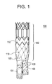
- FIG. 1 shows an anchoring and sealing component 100 of an aneurysm repair system.
- the anchoring and sealing component 100 comprises a trunk section 102 and a bifurcated section, including two legs 104, 106.
- Graft material 108 is affixed to at least a portion of the trunk section 102 and to all of the legs 104, 106.
- the graft material may be attached via any number of means.
- the graft material 108 is attached to various portions of the underlying structure by sutures 110.
- the graft material 108 is affixed with a continuous stitch pattern on the end of the trunk section 102 and by single stitches elsewhere. It is important to note that any stitch pattern may be used, and other devices, such as staples, may be used to connect the graft material 108 to the underlying structure.
- the sutures 110 may comprise any suitable biocompatible material that is preferably highly durable and wear resistant.
- the underlying structure of the trunk section 102 comprises a substantially tubular stent structure or lattice comprising multiple stent sections.
- the stent or lattice structure comprises a single row of substantially diamond shaped elements 112 on one end, multiple rows of substantially diamond shaped elements 114 on the other end, a plurality of longitudinal struts 116 and a single, substantially zigzag shaped stent element 117.
- the plurality of longitudinal struts 116 are connected to the apexes of the substantially diamond shaped elements 114.
- the single, substantially zigzag shaped stent element 117 comprises a number of barbs 119 protruding therefrom for anchoring the device in the vessel to be repaired.
- This construction may be used for anchoring and sealing in positions wherein there are branches off the main artery.
- this exemplary embodiment may be used for supra-renal anchoring.
- the graft material 108 is only attached below the longitudinal struts 116 so that blood may flow into the renal arteries from the aorta. Infra-renal designs are also possible.
- the underlying structure of the bifurcated section comprises a plurality of individual, substantially tubular stent elements 118.
- Each stent element 118 comprises a substantially zigzag pattern.
- leg 104 comprises three stent elements 118a, 118b, 118c and leg 106 comprises two stent elements 118d, 118e.
- the stent elements do not line up and the legs are of two different lengths. This design allows for nesting of the legs 104, 106 such that the profile of the device is reduced.
- the legs are connected at the bifurcation as illustrated in Figure 1 .
- the legs 104, 106 may be connected in any suitable manner. In the construction, the two legs 104, 106 are connected by suturing them together.
- the sutures 120 connect the graft material 108 on each leg 104, 106 together.
- the sutures may be non-biodegradable or biodegradable. Biodegradable sutures would dissolve over time thereby allowing the two legs to move independently.
- Figure 3 shows an endovascular graft 300 of an aneurysm repair system, which comprises one or more first stent segments 310, one second stent segment 320 and a third stent segment 330.
- the third stent segment 330 would be anchored in healthy tissue below the aneurysm and the uppermost first stent segment 310 would be in fluid communication with the anchoring and sealing component 100.
- the second stent segment 320 comprises a tapered profile, having a diameter at one end equal to that of the first stent segment 310 and a diameter at the other end equal to that of the third stent segment 330.
- the length of the endovascular graft 300 may be adjusted by varying the number of first stent segments 310 used.
- Figure 4 shows an embodiment of the third stent segment 330.
- the third stent segment 330 comprises a plurality of struts 332 connected in a substantially zigzag pattern.
- the exemplary third stent segment 330 comprises three sets of zigzag-connected struts 332, thereby forming substantially diamond-shaped cells.
- the non- connected apex 334 of each diamond shaped cell illustrated in greater detail in Figure 4A , comprises a smooth, uniform width curved region formed at the intersection of two struts 332 of each diamond-shaped cell. This shape is cut directly into the stent segment 330 during the initial machining steps, typically laser cutting, and is maintained during all subsequent finishing processing.
- junctions 336 between the zigzag- connected struts 332, illustrated in greater detail in Figure 4B occurs at the intersection of four struts 332.
- each junction 336 of four struts 332 comprises two indentations 338 and 340 as shown in Figure 4B .
- the regions close to the non-connected apexes 334 and the junctions 336 are generally the highest stress regions in the third stent segment 330. To minimise stresses in these regions, these regions are designed to maintain uniform beam widths close to where the struts 332 interconnect. Beam width refers to the width of a strut junction 336. Indentations 338 and 340 are cut or machined into the junctions 336 to maintain a uniform beam width in this area, which is generally subject to the highest stress.
- junctions 336 Essentially, by designing the junctions 336 to maintain uniform beam widths, the stress and strain that would normally build up in a concentrated area, proximate the junction 336, is allowed to spread out into the connecting regions, thereby lowering the peak values of the stress and strain in the stent structure.
- the struts 332 may have a tapering width in order to minimise the maximum stresses in the struts 332 of the third stent segment 330 further.
- a struts 332 may be designed to become wider as it approaches a junction 336.
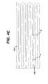
- Figure 4C is an enlarged partial view of the third sent segment 330 in its expanded conditions which illustrates the tapering width of the struts 332.
- the strut 332 proximate the junction 336 (width a) is about 0.025 cm and gradually tapers to a dimension of about 0.0178 cm in the mid-region of the strut 332 (width b).
- the stresses in the struts 332 adjacent the junction 336 is spread out away from the junction 336.
- the tapering of the struts 332 is accomplished during the machining of the tube of material from which the stent 330 is cut.
- the stent segment 330 becomes somewhat less resistant to localized deformations, caused for example, by a protrusion within the vessel lumen. This localized deformation may lead to a local torsional loading on some of the struts 332, and, therefore, since the struts 332 in this embodiment have a relatively significant portion of their length with a reduced width, their torsional rigidity is reduced.
- the struts 332 may be maintained at a uniform width, or more preferably have a reverse taper, as illustrated in Figure 4D , wherein the width at point a is less than the width at point b.
- the reverse taper struts 332 are about 0.025 cm close to the junction 336 and about 0.028 cm in the central region of the struts. While this reverse taper tends to increase the stresses somewhat proximate the junctions 336, this increase is very small relative to the decrease in stresses gained by having the side indentations 338, 340 illustrated in Figure 4B , as well as the uniform width connections illustrated in Figure 4A .
- the stent structure resists local deformation and tends to maintain a substantially circular cross-sectional geometry, even if the lumen into which the stent is positioned in non-circular in cross-section.
- the third stent segment 330 is fabricated from a laser cut tube, of initial dimensions 0.229 cm inside diameter by 0.318 cm outside diameter.
- the struts 332 are preferably 0.0229 cm wide adjacent the four strut junctions 336 and 6 mm long, with a reverse taper strut width.
- the third stent segment 330 have an expanded diameter of 16 mm.
- the proximal portion of the graft material forming the legs is flared, having a diameter of 16 mm.
- This single diameter for the third stent segment of the graft system would enable its use in arteries having a non-aneurysmal region of a diameter from between 8 and 14 mm in diameter. It is also contemplated that multiple diameter combinations of third stent segment 330 and graft flare would be desirable.
- the one or more first stent segments 310 are also formed from a shape set laser cut tube, similar to the third stent segment 330 described above.
- the one or more first stent segments 310 comprise a single circumferential row of zigzag or sinusoidally arranged elements.
- the first stent segment 310 comprises ten zigzag or sinusoidal undulations.
- the one or more first stent segments 310 are formed with uniform width connections at the intersections 314 of the struts 312 forming the zigzag or sinusoidal pattern.
- the one or more first stent segments 310 are preferably cut from tubing having an inside diameter of 0.251 cm and an outside diameter of 0.317 cm.
- the strut widths are preferably about 0.33 cm wide adjacent strut intersections 314 and the struts 312 are preferably 7 mm long and the one or more first stent segments 310 are preferably 11 mm in diameter when expanded.
- the second stent segment 320 comprises a tapered profile, having a diameter at one end which is the same as the one or more first stent segments 310, and a diameter at the other end matching the diameter of the third stent segment 330.
- the second stent segment 320 is identical to the one or more first stent segments 310 except for the taper.
- the stent segments 310, 320 and 330 are secured in position by the graft material.
- Nickel titanium based shape memory alloys are used in a wide variety of applications, including medical device applications as described herein.
- NiTi alloys are widely used in the fabrication or construction of medical devices for a number of properties, including biomechanical compatibility, biocompatibility, fatigue resistance, kink resistance, uniform plastic deformation, magnetic resonance imaging compatibility, constant and gentle outward pressure, dynamic interference, thermal deployment capability, elastic deployment capability, hysteresis characteristics and radio-opacity.
- Nickel titanium based alloys can exhibit shape memory including superelastic characteristics.
- Shape memory characteristics may be simplistically described as follows.
- a NiTi metallic structure, for example a tube, that is in an austenite phase may be cooled to a temperature such that it is in the martensite phase. Once in the martensite, the tube may be deformed into a particular configuration or shape by the application of stress. As long as the tube is maintained in the martensite phase, the tube will remain in its deformed shape. If the tube is heated to a temperature sufficient to cause the alloy to reach the austenite phase, the tube will return to its original or programmed shape. The original shape is programmed to be a particular shape by well known techniques.
- Superelastic characteristics may be simplistically described as follows.
- a metallic structure for example, a tube that is in an austenite phase may be deformed to a particular shape or configuration by the application of mechanical energy.
- the application of mechanical energy causes a stress induced martensite phase transformation.
- the mechanical energy causes the tube to transform from the austenite phase to the martensite phase.
- the tube undergoes another mechanical phase transformation back to the austenite phase and thus its original or programmed shape.
- the original shape is programmed by well known techniques.
- the martensite and austenite phases are common phases in many metals.
- the martensite phase is the low temperature phase.
- a material in the martensite phase is typically very soft and malleable. These properties make it easier to shape or configure articles made from the alloy into complicated or complex structures.
- the austenite phase is the high temperature phase. A material in the austenite phase is generally much stronger than the material in the martensite phase.
- many medical devices are cooled to the martensite phase for manipulation and loading into delivery systems, as described above with respect to stents and then when the device is deployed at body temperature, they return to the austenite phase.
- the first, second and third stent segments 310, 320, 330 are preferably self-expandable and formed from a shape memory alloy. Such an alloy may be deformed from an original, heat-stable configuration to a second, heat-unstable configuration. The application of a desired temperature causes the alloy to revert to an original heat-stable configuration.
- a particularly preferred shape memory alloy for this application is binary nickel titanium alloy comprising about 55.8 percent Ni by weight. This NiTi alloy undergoes a phase transformation at physiological temperatures.
- a stent made of this material is deformable when chilled. Thus, at low temperatures, for example, below 20°C, the stent is compressed so that it can be delivered to the desired location.
- the stent may be kept at low temperatures by circulating chilled saline solutions. The stent expands when the chilled saline is removed and it is exposed to higher temperatures within the patient's body, generally around 37°C.
- each stent is fabricated from a single piece of alloy tubing.
- the tubing is laser cut, shape-set by placing the tubing on a mandrel, and heat-set to its desired expanded shape and size.
- the shape setting is performed in stages at five hundred degrees centigrade. That is, the stents are placed on sequentially larger mandrels and briefly heated to five hundred degrees centigrade. To minimize grain growth, the total time of exposure to a temperature of 500°C is limited to five minutes. The stents are given their final shape set for four minutes at 550°C, and then aged to a temperature of 475 °C to set a desired martensite to austenite transformation temperature, then blasted, as described in detail subsequently, before electropolishing. This heat treatment process provides for a stent that has a martensite to austenite transformation which occurs over a relatively narrow temperature range; for example, around 15°C.
- the rough edges left by the laser cutting are removed by combination of mechanical grit blasting and electropolishing.
- the grit blasting is performed to remove the brittle recast layer left by the laser cutting process. This layer is not readily removable by the electropolishing process, and if left intact, could lead to a brittle fracture of the stent struts.
- a solution of seventy percent methanol and thirty percent nitric acid at a temperature of-40°C or less has been shown to work effectively as an electropolishing solution.
- Electrical parameters of the electropolishing are selected to remove approximately 0.00127 cm of material from the surfaces of the struts.
- the clean, electropolished surface is the final desired surface for attachment to the graft materials. This surface has been found to import good corrosion resistance, fatigue resistance, and wear resistance.
- the graft material or component 600 may be made from any number of suitable biocompatible materials, including woven, knitted, sutured, extruded, or cast materials comprising polyester, polytetrafluoroethylene, silicones, urethanes, and ultralight weight polyethylene, such as that commercially sold under the trade mark SPECTRA.
- the materials may be porous or nonporous.
- Exemplary materials include a woven polyester fabric made from a polyester such as that sold under the trade mark DACRON.
- the fabric for the graft material is a forty denier (denier is defined as the weight in grams of nine thousand metres of a filament or yarn) twenty-seven filament polyester yarn, having about seventy to one-hundred end yarns per cm and thirty-two to forty-six pick yarns per cm. At this weave density, the graft material is relatively impermeable to blood flow through the wall, but is relatively thin, ranging between 0.08 and 0.12 mm in wall thickness.
- the graft component 600 is a single lumen tube and preferably has a taper and flared portion woven directly from the loom, as illustrated for the endovascular graft 300 shown in Figure 3 .
- crimps Prior to attachment of the graft component 600 to the stents 310, 320, 330, crimps are formed between the stent positions by placing the graft material on a shaped mandrel and thermally forming indentations in the surface.
- the crimps 602 in the graft 400 are about 2 mm long and 0.5 mm deep. With these dimensions, the endovascular graft 300 can bend and flex while maintaining an open lumen.
- the graft material is cut in a shape to mate with the end of each end stent.
- each of the stent segments 310, 320 and 330 is attached to the graft material 600.
- the graft material 600 may be attached to the stent segments 310, 320, 330 in any number of suitable ways.
- the graft material 600 may be attached to the stent segments 310, 320, 330 by sutures.
- the method of suturing stents in place is important for minimizing the relative motion or rubbing between the stent struts and the graft material. Because of the pulsatile motion of the vasculature and therefore the graft system, it is possible for relative motion to occur, particularly in areas where the graft system is in a bend, or if there are residual folds in the graft material, due to being constrained by the aorta or iliac arteries.
- each strut of each stent segment is secured to the graft material by sutures.
- the suture material is blanket stitched to the stent segments at numerous points to securely fasten the graft material to the stent segments.
- a secure hold is desirable in preventing relative motion in an environment in which the graft system experiences dynamic motion arising from pulsatile blood pressure, in addition to pulsation of the arteries that are in direct mechanical contact with the graft system.
- the stents nearest the aortic and iliac ends of the graft system are subject to the pulsatile motion arising from direct internal contact.
- the stitches 604 on the upper most first stent segment 310 are positioned along the entire zigzag arrangement of struts.
- the upper and lower apexes of the third stent segment may be stitched utilizing a similar configuration. It is difficult to manipulate the suture thread precisely around the struts that are located some distance away from an open end, accordingly, various other simpler stitches may be used on these struts, or no stitches may be used in these areas.
- each of the struts in the first stent segment 310 is secured to the graft material 600 which has been cut to match the shape of the stent segment 310.
- the blanket stitching 604 completely encircles the strut and bites into the graft material 600.
- the stitch 604 encircles the strut at approximately five equally spaced locations.
- Each of the struts on each end of the third stent segment 330 is attached to the graft material, which has been cut to make the shape of the stent segment 330, in the same manner as the first stent segment 310.
- a significant portion of the graft will not rest directly against vascular tissue. This portion of the graft will be within the dilated aneurysm itself. Therefore, this portion of the graft will not experience any significant pulsatile motion. For this reason, it is not necessary to secure the stent segments to the graft material as aggressively as the stent structure described above. Therefore, only point stitches 606 are necessary for securing these stents.
- the invention provides means for attaching graft material to stent structures in such a manner as to reduce or even to eliminate this relative motion.
- the means may be used in any of the stent structures described herein, including the stents forming the trunk section and bifurcated section of the anchoring and sealing component of the repair device and the first, second and third stent segments of the endovascular graft.
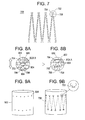
- Figure 7 shows a modified stent cell 700 design.
- the modified stent cell 700 comprises a more complex or modified apex 702 that is designed to more securely attach the graft to the stent while allowing the graft material to move with the apex as shown in Figures 8A and 8B and described below.
- the modified apex 702 comprises a tab like structure 704 and a narrow neck structure 706. This configuration allows the sutures to be connected using a delta stitch as described in more detail below.
- This modified apex 702 may comprise other suitable configurations and sizes so long as it allows for securely holding the delta stitch or any other stitch or attaching elements, and does not significantly affect the size of the overall device.
- the modified apex 702 may comprise radiopaque material such as tantalum and serve a dual role as holder and marker.
- Figures 8A and 8B show the more complex apex 702 relative to the graft material 802 forming the particular component.
- the more complex modified apex 702 is secured to the graft material 802 by any suitable, non-biodegradable or non-bioerodable suture material 804 utilizing a delta stitch.
- the delta stitch is so named because when looked at as a single entity, the stitching pattern forms a substantially delta configuration.
- the delta stitch suture 804 fits around two struts 708 and the narrow neck structure 706. With this configuration, the apex itself holds two legs of the delta stitch in position, and the combination of the narrow neck structure 706 along with the tab 704 holds the third leg of the delta stitch in position.
- Any stitch may be used and that if so desired, the stitching material may be made out of a degradable material. Using a degradable stitch material allows for an acute connection, but also allows for removal of a component if desired after the material degrades.
- this unique arrangement not only holds the graft to the stent, but also allows for movement of the graft together with the stent, thereby ensuring minimal or substantially no relative movement.
- the black square 806 of the graft material 802 is always maintained in position behind the tab 704 even though the stent structure moves and changes shape. Without this relative movement, wear is reduced.
- the graft material itself may comprise openings for securing the more complex apex 702 shown in Figures 7, 8A and 8B .
- Figure 9A shows a substantially cylindrical section of graft material 902 comprising a plurality of openings or slits 904. These slits 904 are designed large enough for the tabs 704 of the stent to go through, but small enough to hold them in place as shown in Figure 9B with the stent struts 708 shown in phantom.
- FIG. 7 A modified apex having a protrusion was used in the embodiment shown in Figure 7 .
- Figure 10 shows a modified apex 1002 having a necked down region 1004 for holding a stitch or other suitable holding device such as a clip or staple.
- Figure 11 shows a modified apex 1102 having multiple holes 1104 for securing a stitch or other suitable securing devices.
- a modified apex 1202 may comprise a series of indents or notches 1204 to hold the attachment means. In each of these embodiments, there is an attachment section but no protrusion.
- the invention may be used on one, every other one or any combination of apexes.
- the present invention works more effectively on zigzag shaped structures and less effectively on closed shaped structures such as diamonds.
Landscapes
- Health & Medical Sciences (AREA)
- Gastroenterology & Hepatology (AREA)
- Pulmonology (AREA)
- Cardiology (AREA)
- Oral & Maxillofacial Surgery (AREA)
- Transplantation (AREA)
- Engineering & Computer Science (AREA)
- Biomedical Technology (AREA)
- Heart & Thoracic Surgery (AREA)
- Vascular Medicine (AREA)
- Life Sciences & Earth Sciences (AREA)
- Animal Behavior & Ethology (AREA)
- General Health & Medical Sciences (AREA)
- Public Health (AREA)
- Veterinary Medicine (AREA)
- Prostheses (AREA)
- Media Introduction/Drainage Providing Device (AREA)
- Materials For Medical Uses (AREA)
Abstract
Description
- The present invention relates to aneurysm repair devices, and more particularly, to devices for attaching graft material to intraluminal scaffolds or stents to eliminate the relative movement between the graft material and the stent.
- An aneurysm is an abnormal dilation of a layer or layers of an arterial wall, usually caused by a systemic collagen synthetic or structural defect. An abdominal aortic aneurysm is an aneurysm in the abdominal portion of the aorta, usually located in or near one or both of the two iliac arteries or near the renal arteries. The aneurysm often arises in the infrarenal portion of the diseased aorta, for example, below the kidneys. A thoracic aortic aneurysm is an aneurysm in the thoracic portion of the aorta. When left untreated, the aneurysm may rupture, usually causing rapid fatal haemorrhaging.
- Aneurysms may be classified or typed by their position as well as by the number of aneurysms in a cluster. Typically, abdominal aortic aneurysms may be classified into five types. A Type I aneurysm is a single dilation located between the renal arteries and the iliac arteries. Typically, in a Type I aneurysm, the aorta is healthy between the renal arteries and the aneurysm and between the aneurysm and the iliac arteries.
- A Type II A aneurysm is a single dilation located between the renal arteries and the iliac arteries. In a Type II A aneurysm, the aorta is healthy between the renal arteries and the aneurysm, but not healthy between the aneurysm and the iliac arteries. In other words, the dilation extends to the aortic bifurcation. A Type II B aneurysm comprises three dilations. One dilation is located between the renal arteries and the iliac arteries. Like a Type II A aneurysm, the aorta is healthy between the aneurysm and the renal arteries, but not healthy between the aneurysm and the iliac arteries. The other two dilations are located in the iliac arteries between the aortic bifurcation and the bifurcations between the external iliacs and the internal iliacs. The iliac arteries are healthy between the iliac bifurcation and the aneurysms. A Type II C aneurysm also comprises three dilations. However, in a Type II C aneurysm, the dilations in the iliac arteries extend to the iliac bifurcation.
- A Type III aneurysm is a single dilation located between the renal arteries and the iliac arteries. In a Type III aneurysm, the aorta is not healthy between the renal arteries and the aneurysm. In other words, the dilation extends to the renal arteries.
- A ruptured abdominal aortic aneurysm is presently the thirteenth leading cause of death in the United States. The routine management of abdominal aortic aneurysms has been surgical bypass, with the placement of a graft in the involved or dilated segment. Although resection with a synthetic graft via a transperitoneal or retroperitoneal procedure has been the standard treatment, it is associated with significant risk. For example, complications include perioperative myocardial ischemia, renal failure, erectile impotence, intestinal ischemia, infection, lower limb ischemia, spinal cord injury with paralysis, aorta-enteric fistula, and death. Surgical treatment of abdominal aortic aneurysms is associated with an overall mortality rate of five percent in asymptomatic patients, sixteen to nineteen percent in symptomatic patients, and is as high as fifty percent in patients with ruptured abdominal aortic aneurysms.
- Disadvantages associated with conventional surgery, in addition to the high mortality rate, include an extended recovery period associated with the large surgical incision and the opening of the abdominal cavity, difficulties in suturing the graft to the aorta, the loss of the existing thrombosis to support and reinforce the graft, the unsuitability of the surgery for many patients having abdominal aortic aneurysms, and the problems associated with performing the surgery on an emergency basis after the aneurysm has ruptured. Further, the typical recovery period is from one to two weeks in the hospital and a convalescence period, at home, ranging from two to three months or more, if complications ensue. Since many patients having abdominal aortic aneurysms have other chronic illnesses, such as heart, lung, liver and/or kidney disease, coupled with the fact that many of these patients are older, they are less than ideal candidates for surgery.
- The occurrence of aneurysms is not confined to the abdominal region. While abdominal aortic aneurysms are generally the most common, aneurysms in other regions of the aorta or one of its branches are possible. For example, aneurysms may occur in the thoracic aorta. As is the case with abdominal aortic aneurysms, the widely accepted approach to treating an aneurysm in the thoracic aorta is surgical repair, involving replacing the aneurysmal segment with a prosthetic device. This surgery, as described above, is a major undertaking, with associated high risks and with significant mortality and morbidity.
- Endovascular (catheter directed) techniques for the treatment of aneurysms, specifically abdominal aortic aneurysms, have been developed. This has been facilitated by the development of vascular stents, which can and have been used in conjunction with standard or thin-wall graft material in order to create a stent-graft or endograft. The potential advantages of less invasive treatments have included reduced surgical morbidity and mortality along with shorter hospital and intensive care unit stays.
- Stent-grafts or endoprostheses are now Food and Drug Administration (FDA) approved and commercially available. Their delivery procedure typically involves advanced angiographic techniques performed through vascular accesses gained via surgical cut down of a remote artery, which may include the common femoral or brachial arteries. Over a guidewire, the appropriate size introducer will be placed. The catheter and guidewire are passed through the aneurysm. Through the introducer, the stent-graft will be advanced to the appropriate position. Typical deployment of the stent-graft device requires withdrawal of an outer sheath while maintaining the position of the stent-graft with an inner-stabilizing device. Most stent-grafts are self-expanding; however, an additional angioplasty procedure, e.g., balloon angioplasty, may be required to secure the position of the stent-graft. Following the placement of the stent-graft, standard angiographic views may be obtained.
- Due to the large diameter of the above-described devices, typically greater than twenty French (3F=1 mm), arteriotomy closure typically requires open surgical repair. Some procedures may require additional surgical techniques, such as hypogastric artery embolization, vessel ligation, or surgical bypass in order to adequately treat the aneurysm or to maintain blood flow to both lower extremities. Likewise, some procedures will require additional advanced catheter directed techniques, such as angioplasty, stent placement and embolisation, in order to successfully exclude the aneurysm and efficiently manage leaks.
- While the above-described endoprostheses represent a significant improvement over conventional surgical techniques, there is a need to improve the endoprostheses, their method of use and their applicability to varied biological conditions. Accordingly, in order to provide a safe and effective alternate means for treating aneurysms, including abdominal aortic aneurysms and thoracic aortic aneurysms, a number of difficulties associated with currently known endoprostheses and their delivery systems must be overcome. One concern with the use of endoprostheses is the prevention of endo-leaks and the disruption of the normal fluid dynamics of the vasculature. Devices using any technology should preferably be simple to position and reposition as necessary, should preferably provide an acute, fluid tight seal, and should preferably be anchored to prevent migration without interfering with normal blood flow in both the aneurysmal vessel as well as branching vessels. In addition, devices using the technology should preferably be able to be anchored, sealed, and maintained in bifurcated vessels, tortuous vessels, highly angulated vessels, partially diseased vessels, calcified vessels, odd shaped vessels, short vessels, and long vessels. In order to accomplish this, the endoprostheses should preferably be highly durable, extendable and re-configurable while maintaining acute and long-term fluid tight seals and anchoring positions.
- The endoprostheses should also preferably be able to be delivered percutaneously utilizing catheters, guidewires and other devices which substantially eliminate the need for open surgical intervention. Accordingly, the diameter of the endoprostheses in the catheter is an important factor. This is especially true for aneurysms in the larger vessels, such as the thoracic aorta. In addition, the endoprostheses should preferably be percutaneously delivered and deployed such that surgical cut down is unnecessary.
- Many aneurysm repair devices currently in the market utilize a woven Dacron® graft material and a metallic stent or scaffold. Typically, the stents are attached to the graft material by sutures. Even though the stents are sutured in place, this does not completely eliminate relative movement between the stent and the graft material caused by the pulsatile movement of the blood in the particular artery and the movement of the artery itself. This relative motion between the stent and the graft causes wear and potentially a separation or opening between the graft and the stent. This potential separation or opening may in turn lead to endo leaks. Accordingly, it would be highly advantageous to develop a system for preventing this or substantially eliminating relative movement between the stent and the graft.
- The present invention overcomes the disadvantages associated with currently used aneurysm repair devices that exhibit relative motion between the components of the system as briefly described above.
- In one aspect, the invention provides an aneurysm repair system which comprises at least one substantially cylindrical stent segment and graft material affixed, via attachment elements, to the at least one substantially cylindrical stent segment. The at least one substantially cylindrical stent segment comprises a substantially zigzag shaped configuration with attachment sections proximate at least one apex.
- In another aspect, the invention provides an aneurysm repair system which comprises at least one substantially cylindrical stent segment and graft material affixed to the at least one substantially cylindrical stent segment. The graft material comprises a plurality of openings and the substantially cylindrical stent segment comprises a substantially zigzag shaped configuration with attachment sections proximate at least one apex that are configured to be positioned and secured with the plurality of openings in the graft material.
- A majority of aneurysm repair devices such as abdominal aortic aneurysm repair devices currently on the market utilize a woven synthetic fibre graft material and a metallic stent. Typically, the stents are attached to the graft material by sutures. Even with the stents sutured in place, this does not completely eliminate stent movement caused by the pulsatile movement of the vessel, e.g. the aorta. This relative motion between the stent and the graft is what causes fibre wear and potential fibre separation. In other words, the pulsatile motion of the vessel causes the stent to rub against the graft material potentially resulting in holes that cause endoleaks. Accordingly, the present invention is directed to a unique stent apex configuration and its attachment method to prevent or substantially eliminate any relative motion between the stent and the graft. In addition to the stent shape, a unique attachment method, the so called the delta stitch is added to ensure better security at the attachment site.
- Embodiments of the invention are described below by way of example with reference to the accompanying drawings, in which:
-
Figure 1 is a diagrammatic representation of the exemplary anchoring and sealing prosthesis in accordance with the present invention. -
Figure 2 is a diagrammatic representation of an exemplary anchoring and sealing prosthesis with no graft material and/or stitching in certain locations in accordance with the present invention. -
Figure 3 is an elevational view of an endovascular graft in accordance with the present invention. -
Figure 4 is a perspective view of an expanded stent segment of the endovascular graft in accordance with the present invention. -
Figure 4A is a fragmentary perspective view of a portion of the stent segment ofFigure 4 . -
Figure 4B is a fragmentary perspective view of a portion of the stent segment ofFigure 4 . -
Figure 4C is an enlarged plan view of a section of the stent segment ofFigure 4 . -
Figure 4D is an enlarged plan view of a section of the stent segment ofFigure 4 . -
Figure 5 is a perspective view of another expanded stent segment of the endovascular graft in accordance with the present invention. -
Figure 6 is an elevational view of an endovascular graft in accordance with the present invention. -
Figure 7 is a diagrammatic representation of a stent segment having a first modified apex design in accordance with the present invention. -
Figures 8A and 8B are diagrammatic representations of a portion of the modified apex as it is attached to the graft material in accordance with the present invention. -
Figure 9A is a diagrammatic presentation of a modified graft in accordance with the present invention. -
Figure 9B is a diagrammatic representation of a modified stent-graft in accordance with the present invention. -
Figure 10 is a diagrammatic representation of a stent segment having a second modified apex design in accordance with the present invention. -
Figure 11 is a diagrammatic representation of a stent segment having a third modified apex design in accordance with the present invention. -
Figure 12 is a diagrammatic representation of a stent segment having a fourth modified apex design in accordance with the present invention. - Referring to the drawings,
Figure 1 shows an anchoring and sealingcomponent 100 of an aneurysm repair system. The anchoring and sealingcomponent 100 comprises atrunk section 102 and a bifurcated section, including twolegs Graft material 108, described in detail below, is affixed to at least a portion of thetrunk section 102 and to all of thelegs graft material 108 is attached to various portions of the underlying structure bysutures 110. As illustrated, thegraft material 108 is affixed with a continuous stitch pattern on the end of thetrunk section 102 and by single stitches elsewhere. It is important to note that any stitch pattern may be used, and other devices, such as staples, may be used to connect thegraft material 108 to the underlying structure. Thesutures 110 may comprise any suitable biocompatible material that is preferably highly durable and wear resistant. - The underlying structure of the
trunk section 102, as shown inFigure 2 , comprises a substantially tubular stent structure or lattice comprising multiple stent sections. The stent or lattice structure comprises a single row of substantially diamond shapedelements 112 on one end, multiple rows of substantially diamond shapedelements 114 on the other end, a plurality oflongitudinal struts 116 and a single, substantially zigzag shapedstent element 117. The plurality oflongitudinal struts 116 are connected to the apexes of the substantially diamond shapedelements 114. The single, substantially zigzag shapedstent element 117 comprises a number ofbarbs 119 protruding therefrom for anchoring the device in the vessel to be repaired. This construction may be used for anchoring and sealing in positions wherein there are branches off the main artery. For example, this exemplary embodiment may be used for supra-renal anchoring. Accordingly, thegraft material 108 is only attached below thelongitudinal struts 116 so that blood may flow into the renal arteries from the aorta. Infra-renal designs are also possible. - The underlying structure of the bifurcated section, as shown in
Figure 2 , comprises a plurality of individual, substantiallytubular stent elements 118. Eachstent element 118 comprises a substantially zigzag pattern. As illustrated,leg 104 comprises threestent elements leg 106 comprises twostent elements 118d, 118e. As illustrated, in this construction, the stent elements do not line up and the legs are of two different lengths. This design allows for nesting of thelegs - In order to compensate for the missing stent elements, the legs are connected at the bifurcation as illustrated in
Figure 1 . Thelegs legs sutures 120 connect thegraft material 108 on eachleg -
Figure 3 shows anendovascular graft 300 of an aneurysm repair system, which comprises one or morefirst stent segments 310, onesecond stent segment 320 and athird stent segment 330. In a typical application, thethird stent segment 330 would be anchored in healthy tissue below the aneurysm and the uppermostfirst stent segment 310 would be in fluid communication with the anchoring and sealingcomponent 100. Thesecond stent segment 320 comprises a tapered profile, having a diameter at one end equal to that of thefirst stent segment 310 and a diameter at the other end equal to that of thethird stent segment 330. The length of theendovascular graft 300 may be adjusted by varying the number offirst stent segments 310 used. -
Figure 4 shows an embodiment of thethird stent segment 330. Thethird stent segment 330 comprises a plurality ofstruts 332 connected in a substantially zigzag pattern. The exemplarythird stent segment 330 comprises three sets of zigzag-connectedstruts 332, thereby forming substantially diamond-shaped cells. The non-connected apex 334 of each diamond shaped cell, illustrated in greater detail inFigure 4A , comprises a smooth, uniform width curved region formed at the intersection of twostruts 332 of each diamond-shaped cell. This shape is cut directly into thestent segment 330 during the initial machining steps, typically laser cutting, and is maintained during all subsequent finishing processing. Thejunctions 336 between the zigzag- connectedstruts 332, illustrated in greater detail inFigure 4B occurs at the intersection of four struts 332. Preferably, eachjunction 336 of fourstruts 332 comprises twoindentations Figure 4B . - The regions close to the
non-connected apexes 334 and thejunctions 336 are generally the highest stress regions in thethird stent segment 330. To minimise stresses in these regions, these regions are designed to maintain uniform beam widths close to where thestruts 332 interconnect. Beam width refers to the width of astrut junction 336.Indentations junctions 336 to maintain a uniform beam width in this area, which is generally subject to the highest stress. Essentially, by designing thejunctions 336 to maintain uniform beam widths, the stress and strain that would normally build up in a concentrated area, proximate thejunction 336, is allowed to spread out into the connecting regions, thereby lowering the peak values of the stress and strain in the stent structure. - The
struts 332 may have a tapering width in order to minimise the maximum stresses in thestruts 332 of thethird stent segment 330 further. For example, in one embodiment, astruts 332 may be designed to become wider as it approaches ajunction 336.Figure 4C is an enlarged partial view of thethird sent segment 330 in its expanded conditions which illustrates the tapering width of thestruts 332. In this exemplary embodiment, thestrut 332 proximate the junction 336 (width a) is about 0.025 cm and gradually tapers to a dimension of about 0.0178 cm in the mid-region of the strut 332 (width b). By tapering the widths of the struts, the stresses in thestruts 332 adjacent thejunction 336 is spread out away from thejunction 336. The tapering of thestruts 332 is accomplished during the machining of the tube of material from which thestent 330 is cut. However, by tapering thestruts 332 in this manner, thestent segment 330 becomes somewhat less resistant to localized deformations, caused for example, by a protrusion within the vessel lumen. This localized deformation may lead to a local torsional loading on some of thestruts 332, and, therefore, since thestruts 332 in this embodiment have a relatively significant portion of their length with a reduced width, their torsional rigidity is reduced. - If maximizing the resistance to localized deformation is preferred, the
struts 332 may be maintained at a uniform width, or more preferably have a reverse taper, as illustrated inFigure 4D , wherein the width at point a is less than the width at point b. In this exemplary embodiment, the reverse taper struts 332 are about 0.025 cm close to thejunction 336 and about 0.028 cm in the central region of the struts. While this reverse taper tends to increase the stresses somewhat proximate thejunctions 336, this increase is very small relative to the decrease in stresses gained by having theside indentations Figure 4B , as well as the uniform width connections illustrated inFigure 4A . In addition, since the reverse taper serves to increase the torsional rigidity of thestrut 332, the stent structure resists local deformation and tends to maintain a substantially circular cross-sectional geometry, even if the lumen into which the stent is positioned in non-circular in cross-section. - In a preferred embodiment, the
third stent segment 330 is fabricated from a laser cut tube, of initial dimensions 0.229 cm inside diameter by 0.318 cm outside diameter. Thestruts 332 are preferably 0.0229 cm wide adjacent the fourstrut junctions 336 and 6 mm long, with a reverse taper strut width. Also, to minimize the number of different diameter combination of grafts systems, it is preferred that thethird stent segment 330 have an expanded diameter of 16 mm. Similarly, the proximal portion of the graft material forming the legs is flared, having a diameter of 16 mm. This single diameter for the third stent segment of the graft system would enable its use in arteries having a non-aneurysmal region of a diameter from between 8 and 14 mm in diameter. It is also contemplated that multiple diameter combinations ofthird stent segment 330 and graft flare would be desirable. - Referring back to
Figure 3 , the one or morefirst stent segments 310 are also formed from a shape set laser cut tube, similar to thethird stent segment 330 described above. The one or morefirst stent segments 310 comprise a single circumferential row of zigzag or sinusoidally arranged elements. In the exemplary embodiment illustrated inFigure 3 , and in greater detail inFigure 5 , thefirst stent segment 310 comprises ten zigzag or sinusoidal undulations. The one or morefirst stent segments 310 are formed with uniform width connections at theintersections 314 of thestruts 312 forming the zigzag or sinusoidal pattern. The one or morefirst stent segments 310 are preferably cut from tubing having an inside diameter of 0.251 cm and an outside diameter of 0.317 cm. The strut widths are preferably about 0.33 cm wideadjacent strut intersections 314 and thestruts 312 are preferably 7 mm long and the one or morefirst stent segments 310 are preferably 11 mm in diameter when expanded. - The
second stent segment 320 comprises a tapered profile, having a diameter at one end which is the same as the one or morefirst stent segments 310, and a diameter at the other end matching the diameter of thethird stent segment 330. Thesecond stent segment 320 is identical to the one or morefirst stent segments 310 except for the taper. - As is explained in detail subsequently, the
stent segments - Nickel titanium based shape memory alloys, sometimes referred to collectively as Nitinol, are used in a wide variety of applications, including medical device applications as described herein. NiTi alloys are widely used in the fabrication or construction of medical devices for a number of properties, including biomechanical compatibility, biocompatibility, fatigue resistance, kink resistance, uniform plastic deformation, magnetic resonance imaging compatibility, constant and gentle outward pressure, dynamic interference, thermal deployment capability, elastic deployment capability, hysteresis characteristics and radio-opacity.
- Nickel titanium based alloys can exhibit shape memory including superelastic characteristics. Shape memory characteristics may be simplistically described as follows. A NiTi metallic structure, for example a tube, that is in an austenite phase may be cooled to a temperature such that it is in the martensite phase. Once in the martensite, the tube may be deformed into a particular configuration or shape by the application of stress. As long as the tube is maintained in the martensite phase, the tube will remain in its deformed shape. If the tube is heated to a temperature sufficient to cause the alloy to reach the austenite phase, the tube will return to its original or programmed shape. The original shape is programmed to be a particular shape by well known techniques. Superelastic characteristics may be simplistically described as follows. A metallic structure, for example, a tube that is in an austenite phase may be deformed to a particular shape or configuration by the application of mechanical energy. The application of mechanical energy causes a stress induced martensite phase transformation. In other words, the mechanical energy causes the tube to transform from the austenite phase to the martensite phase. By using the appropriate measuring instruments, one can determine that the stress from the mechanical energy causes a temperature drop in the tube. Once the mechanical energy or stress is released, the tube undergoes another mechanical phase transformation back to the austenite phase and thus its original or programmed shape. As described above, the original shape is programmed by well known techniques. The martensite and austenite phases are common phases in many metals.
- Medical devices constructed from nickel titanium based shape memory alloys are typically used in both the martensite phase and/or the austenite phase. The martensite phase is the low temperature phase. A material in the martensite phase is typically very soft and malleable. These properties make it easier to shape or configure articles made from the alloy into complicated or complex structures. The austenite phase is the high temperature phase. A material in the austenite phase is generally much stronger than the material in the martensite phase. Typically, many medical devices are cooled to the martensite phase for manipulation and loading into delivery systems, as described above with respect to stents and then when the device is deployed at body temperature, they return to the austenite phase.
- The first, second and
third stent segments - In preferred embodiments, each stent is fabricated from a single piece of alloy tubing. The tubing is laser cut, shape-set by placing the tubing on a mandrel, and heat-set to its desired expanded shape and size.
- In preferred embodiments, the shape setting is performed in stages at five hundred degrees centigrade. That is, the stents are placed on sequentially larger mandrels and briefly heated to five hundred degrees centigrade. To minimize grain growth, the total time of exposure to a temperature of 500°C is limited to five minutes. The stents are given their final shape set for four minutes at 550°C, and then aged to a temperature of 475 °C to set a desired martensite to austenite transformation temperature, then blasted, as described in detail subsequently, before electropolishing. This heat treatment process provides for a stent that has a martensite to austenite transformation which occurs over a relatively narrow temperature range; for example, around 15°C.
- To improve the mechanical integrity of the stent, the rough edges left by the laser cutting are removed by combination of mechanical grit blasting and electropolishing. The grit blasting is performed to remove the brittle recast layer left by the laser cutting process. This layer is not readily removable by the electropolishing process, and if left intact, could lead to a brittle fracture of the stent struts. A solution of seventy percent methanol and thirty percent nitric acid at a temperature of-40°C or less has been shown to work effectively as an electropolishing solution. Electrical parameters of the electropolishing are selected to remove approximately 0.00127 cm of material from the surfaces of the struts. The clean, electropolished surface is the final desired surface for attachment to the graft materials. This surface has been found to import good corrosion resistance, fatigue resistance, and wear resistance.
- The graft material or
component 600, as illustrated inFigure 6 , may be made from any number of suitable biocompatible materials, including woven, knitted, sutured, extruded, or cast materials comprising polyester, polytetrafluoroethylene, silicones, urethanes, and ultralight weight polyethylene, such as that commercially sold under the trade mark SPECTRA. The materials may be porous or nonporous. Exemplary materials include a woven polyester fabric made from a polyester such as that sold under the trade mark DACRON. - In one embodiment, the fabric for the graft material is a forty denier (denier is defined as the weight in grams of nine thousand metres of a filament or yarn) twenty-seven filament polyester yarn, having about seventy to one-hundred end yarns per cm and thirty-two to forty-six pick yarns per cm. At this weave density, the graft material is relatively impermeable to blood flow through the wall, but is relatively thin, ranging between 0.08 and 0.12 mm in wall thickness.
- The
graft component 600 is a single lumen tube and preferably has a taper and flared portion woven directly from the loom, as illustrated for theendovascular graft 300 shown inFigure 3 . - Prior to attachment of the
graft component 600 to thestents Figures 3 and6 , thecrimps 602 in the graft 400 are about 2 mm long and 0.5 mm deep. With these dimensions, theendovascular graft 300 can bend and flex while maintaining an open lumen. Also, prior to attachment of thegraft component 600 to thestents - As stated above, each of the
stent segments graft material 600. Thegraft material 600 may be attached to thestent segments graft material 600 may be attached to thestent segments - The method of suturing stents in place is important for minimizing the relative motion or rubbing between the stent struts and the graft material. Because of the pulsatile motion of the vasculature and therefore the graft system, it is possible for relative motion to occur, particularly in areas where the graft system is in a bend, or if there are residual folds in the graft material, due to being constrained by the aorta or iliac arteries.
- Ideally, each strut of each stent segment is secured to the graft material by sutures. In an exemplary embodiment, the suture material is blanket stitched to the stent segments at numerous points to securely fasten the graft material to the stent segments. As stated above, a secure hold is desirable in preventing relative motion in an environment in which the graft system experiences dynamic motion arising from pulsatile blood pressure, in addition to pulsation of the arteries that are in direct mechanical contact with the graft system. The stents nearest the aortic and iliac ends of the graft system (the uppermost
first stent segment 310 and thethird stent segment 330 respectively) are subject to the pulsatile motion arising from direct internal contact. These struts in particular should be well secured to the graft material. As shown inFigure 6 , thestitches 604 on the upper mostfirst stent segment 310 are positioned along the entire zigzag arrangement of struts. The upper and lower apexes of the third stent segment may be stitched utilizing a similar configuration. It is difficult to manipulate the suture thread precisely around the struts that are located some distance away from an open end, accordingly, various other simpler stitches may be used on these struts, or no stitches may be used in these areas. - As shown in
Figure 6 , each of the struts in thefirst stent segment 310 is secured to thegraft material 600 which has been cut to match the shape of thestent segment 310. Theblanket stitching 604 completely encircles the strut and bites into thegraft material 600. Preferably, thestitch 604 encircles the strut at approximately five equally spaced locations. Each of the struts on each end of thethird stent segment 330 is attached to the graft material, which has been cut to make the shape of thestent segment 330, in the same manner as thefirst stent segment 310. - A significant portion of the graft will not rest directly against vascular tissue. This portion of the graft will be within the dilated aneurysm itself. Therefore, this portion of the graft will not experience any significant pulsatile motion. For this reason, it is not necessary to secure the stent segments to the graft material as aggressively as the stent structure described above. Therefore, only point
stitches 606 are necessary for securing these stents. - It is important to note that a wide variety of sutures are available. It is equally important to note that there are a number of alternative means for attaching the graft material to the stent, including welding, gluing and chemical bonding.
- As described above with respect to suturing stents in place, it is important to minimise or at least to reduce significantly the relative motion or rubbing between the stent struts and the graft material. This relative motion arises from pulsatile blood pressure in addition to the pulsation of the arteries that are in direct mechanical contact with the graft system.
- The invention provides means for attaching graft material to stent structures in such a manner as to reduce or even to eliminate this relative motion. The means may be used in any of the stent structures described herein, including the stents forming the trunk section and bifurcated section of the anchoring and sealing component of the repair device and the first, second and third stent segments of the endovascular graft.
-
Figure 7 shows a modifiedstent cell 700 design. As shown, rather than asimple apex 334 as illustrated inFigure 4 , the modifiedstent cell 700 comprises a more complex or modifiedapex 702 that is designed to more securely attach the graft to the stent while allowing the graft material to move with the apex as shown inFigures 8A and 8B and described below. The modifiedapex 702 comprises a tab likestructure 704 and anarrow neck structure 706. This configuration allows the sutures to be connected using a delta stitch as described in more detail below. This modifiedapex 702 may comprise other suitable configurations and sizes so long as it allows for securely holding the delta stitch or any other stitch or attaching elements, and does not significantly affect the size of the overall device. The modifiedapex 702 may comprise radiopaque material such as tantalum and serve a dual role as holder and marker. -
Figures 8A and 8B show the morecomplex apex 702 relative to thegraft material 802 forming the particular component. In both figures, the more complex modifiedapex 702 is secured to thegraft material 802 by any suitable, non-biodegradable ornon-bioerodable suture material 804 utilizing a delta stitch. The delta stitch is so named because when looked at as a single entity, the stitching pattern forms a substantially delta configuration. Thedelta stitch suture 804 fits around twostruts 708 and thenarrow neck structure 706. With this configuration, the apex itself holds two legs of the delta stitch in position, and the combination of thenarrow neck structure 706 along with thetab 704 holds the third leg of the delta stitch in position. Any stitch may be used and that if so desired, the stitching material may be made out of a degradable material. Using a degradable stitch material allows for an acute connection, but also allows for removal of a component if desired after the material degrades. - As set forth above, this unique arrangement not only holds the graft to the stent, but also allows for movement of the graft together with the stent, thereby ensuring minimal or substantially no relative movement. The
black square 806 of thegraft material 802 is always maintained in position behind thetab 704 even though the stent structure moves and changes shape. Without this relative movement, wear is reduced. - In an alternative embodiment, the graft material itself may comprise openings for securing the more
complex apex 702 shown inFigures 7, 8A and 8B . With this type of configuration, no sutures or other attachment means or elements may be required.Figure 9A shows a substantially cylindrical section ofgraft material 902 comprising a plurality of openings or slits 904. Theseslits 904 are designed large enough for thetabs 704 of the stent to go through, but small enough to hold them in place as shown inFigure 9B with the stent struts 708 shown in phantom. - A modified apex having a protrusion was used in the embodiment shown in
Figure 7 . However, constructions can be used which do not incorporate a protrusion. For example,Figure 10 shows a modifiedapex 1002 having anecked down region 1004 for holding a stitch or other suitable holding device such as a clip or staple.Figure 11 shows a modifiedapex 1102 havingmultiple holes 1104 for securing a stitch or other suitable securing devices. In another embodiment which is shown inFigure 12 , a modifiedapex 1202 may comprise a series of indents ornotches 1204 to hold the attachment means. In each of these embodiments, there is an attachment section but no protrusion. In addition, although shown and described as being on every apex, the invention may be used on one, every other one or any combination of apexes. - The present invention works more effectively on zigzag shaped structures and less effectively on closed shaped structures such as diamonds.
Claims (9)
- An aneurysm repair system comprising:at least one substantially cylindrical stent segment; andgraft material which is fixed by means of attachment elements to the at least one substantially cylindrical stent segment, the at least one substantially cylindrical stent segment comprising a substantially zigzag shaped configuration with attachment sections proximate at least one apex.
- The aneurysm repair system according to Claim 1, in which the attachment sections each comprise a narrow neck and tab structure.
- The aneurysm repair system according to claim 2, in which the attachment elements comprise sutures.
- The aneurysm repair system according to claim 3, in which the sutures are arranged in a substantially delta shaped configuration.
- The aneurysm repair system according to claim 1, in which the substantially cylindrical stent segment comprises a superelastic material.
- The aneurysm repair system according to claim 5, in which the superelastic material comprises a nickel-titanium alloy.
- The aneurysm repair system according to claim 1, in which the substantially cylindrical stent segment comprises a shape memory material.
- The aneurysm repair system according to claim 7, in which the shape memory material comprises a nickel-titanium alloy.
- An aneurysm repair system comprising:at least one substantially cylindrical stent segment; andgraft material affixed to the at least one substantially cylindrical stent segment, the graft material comprising a plurality of openings and the substantially cylindrical stent segment comprises a substantially zigzag shaped configuration with attachment sections proximate at least one apex that are configured to be positioned and secured within the plurality of openings in the graft material.
Applications Claiming Priority (1)
| Application Number | Priority Date | Filing Date | Title |
|---|---|---|---|
| US12/039,937 US8226703B2 (en) | 2008-02-29 | 2008-02-29 | Method and device for attaching a stent structure to AAA graft material |
Publications (2)
| Publication Number | Publication Date |
|---|---|
| EP2095793A1 true EP2095793A1 (en) | 2009-09-02 |
| EP2095793B1 EP2095793B1 (en) | 2011-06-15 |
Family
ID=40793222
Family Applications (1)
| Application Number | Title | Priority Date | Filing Date |
|---|---|---|---|
| EP09152304A Active EP2095793B1 (en) | 2008-02-29 | 2009-02-06 | Device for attaching a stent structure to aaa graft material |
Country Status (5)
| Country | Link |
|---|---|
| US (1) | US8226703B2 (en) |
| EP (1) | EP2095793B1 (en) |
| JP (1) | JP5318604B2 (en) |
| AT (1) | ATE512641T1 (en) |
| CA (2) | CA2944014C (en) |
Cited By (2)
| Publication number | Priority date | Publication date | Assignee | Title |
|---|---|---|---|---|
| EP2301476A1 (en) * | 2009-09-24 | 2011-03-30 | Cordis Corporation | Stent-graft suture locks |
| EP2401989A1 (en) * | 2008-04-17 | 2012-01-04 | Cordis Corporation | Combination barb restraint and stent attachment deployment mechanism |
Families Citing this family (8)
| Publication number | Priority date | Publication date | Assignee | Title |
|---|---|---|---|---|
| CN2817768Y (en) * | 2005-05-24 | 2006-09-20 | 微创医疗器械(上海)有限公司 | Tectorium stand and host cage section thereof |
| DE102010047106A1 (en) | 2010-10-01 | 2012-04-05 | Conti Temic Microelectronic Gmbh | Device, particularly optical device, has objective and carrier housing, where objective is mounted in carrier housing, and objective and carrier housing are connected with each other through adhesive connection |
| US8734504B2 (en) | 2012-04-12 | 2014-05-27 | Sanford Health | Aortic arch double-barreled main body stent graft and methods for use |
| US9132025B2 (en) | 2012-06-15 | 2015-09-15 | Trivascular, Inc. | Bifurcated endovascular prosthesis having tethered contralateral leg |
| US9655754B2 (en) * | 2013-01-10 | 2017-05-23 | Trivascular, Inc. | Systems and methods for guidewire crossover for bifurcated prostheses |
| JP7430061B2 (en) * | 2017-02-21 | 2024-02-09 | シルク・ロード・メディカル・インコーポレイテッド | vascular implant |
| CN109419566B (en) * | 2017-08-28 | 2020-09-29 | 先健科技(深圳)有限公司 | Covered stent |
| US10925713B2 (en) | 2018-08-07 | 2021-02-23 | Cook Medical Technologies Llc | Stitch wire routing and delivery system |
Citations (4)
| Publication number | Priority date | Publication date | Assignee | Title |
|---|---|---|---|---|
| WO2001019286A1 (en) * | 1999-09-15 | 2001-03-22 | Eva Corporation | Method and apparatus for supporting a graft assembly |
| US20030135261A1 (en) * | 1999-12-03 | 2003-07-17 | Kugler Chad J. | Endovascular graft system |
| WO2003075799A1 (en) * | 2002-03-04 | 2003-09-18 | Endovascular Technologies, Inc. | Endovascular graft device and methods for attaching components thereof |
| WO2004017866A1 (en) * | 2002-08-20 | 2004-03-04 | Cook Incorporated | Stent graft with improved proximal end |
Family Cites Families (2)
| Publication number | Priority date | Publication date | Assignee | Title |
|---|---|---|---|---|
| EP1706069B1 (en) * | 2004-01-20 | 2009-07-01 | Cook Incorporated | Endoluminal stent-graft with sutured attachment |
| CN100352406C (en) * | 2004-08-17 | 2007-12-05 | 微创医疗器械(上海)有限公司 | Combined membrane-covered stent capable of being bent in any direction |
-
2008
- 2008-02-29 US US12/039,937 patent/US8226703B2/en not_active Expired - Fee Related
-
2009
- 2009-02-05 CA CA2944014A patent/CA2944014C/en active Active
- 2009-02-05 CA CA2652687A patent/CA2652687C/en active Active
- 2009-02-06 AT AT09152304T patent/ATE512641T1/en not_active IP Right Cessation
- 2009-02-06 JP JP2009025567A patent/JP5318604B2/en not_active Expired - Fee Related
- 2009-02-06 EP EP09152304A patent/EP2095793B1/en active Active
Patent Citations (4)
| Publication number | Priority date | Publication date | Assignee | Title |
|---|---|---|---|---|
| WO2001019286A1 (en) * | 1999-09-15 | 2001-03-22 | Eva Corporation | Method and apparatus for supporting a graft assembly |
| US20030135261A1 (en) * | 1999-12-03 | 2003-07-17 | Kugler Chad J. | Endovascular graft system |
| WO2003075799A1 (en) * | 2002-03-04 | 2003-09-18 | Endovascular Technologies, Inc. | Endovascular graft device and methods for attaching components thereof |
| WO2004017866A1 (en) * | 2002-08-20 | 2004-03-04 | Cook Incorporated | Stent graft with improved proximal end |
Cited By (2)
| Publication number | Priority date | Publication date | Assignee | Title |
|---|---|---|---|---|
| EP2401989A1 (en) * | 2008-04-17 | 2012-01-04 | Cordis Corporation | Combination barb restraint and stent attachment deployment mechanism |
| EP2301476A1 (en) * | 2009-09-24 | 2011-03-30 | Cordis Corporation | Stent-graft suture locks |
Also Published As
| Publication number | Publication date |
|---|---|
| CA2652687C (en) | 2017-04-18 |
| JP2009207887A (en) | 2009-09-17 |
| ATE512641T1 (en) | 2011-07-15 |
| JP5318604B2 (en) | 2013-10-16 |
| US20090222077A1 (en) | 2009-09-03 |
| CA2944014A1 (en) | 2009-08-29 |
| CA2944014C (en) | 2019-04-30 |
| US8226703B2 (en) | 2012-07-24 |
| EP2095793B1 (en) | 2011-06-15 |
| CA2652687A1 (en) | 2009-08-29 |
Similar Documents
| Publication | Publication Date | Title |
|---|---|---|
| US20210093472A1 (en) | Stent attachment and deployment mechanism | |
| CA2662600C (en) | Combination barb restraint and stent attachment deployment mechanism | |
| CA2593587C (en) | Aaa repair device with aneurysm sac access port | |
| EP2266509B1 (en) | Stent - graft securement device | |
| EP2095793B1 (en) | Device for attaching a stent structure to aaa graft material | |
| EP2548532B1 (en) | Stent-graft or graft with durability or stiffness enhancing elements | |
| AU2015215940B2 (en) | Stent attachment and deployment mechanism |
Legal Events
| Date | Code | Title | Description |
|---|---|---|---|
| PUAI | Public reference made under article 153(3) epc to a published international application that has entered the european phase |
Free format text: ORIGINAL CODE: 0009012 |
|
| AK | Designated contracting states |
Kind code of ref document: A1 Designated state(s): AT BE BG CH CY CZ DE DK EE ES FI FR GB GR HR HU IE IS IT LI LT LU LV MC MK MT NL NO PL PT RO SE SI SK TR |
|
| AX | Request for extension of the european patent |
Extension state: AL BA RS |
|
| 17P | Request for examination filed |
Effective date: 20090918 |
|
| 17Q | First examination report despatched |
Effective date: 20091013 |
|
| AKX | Designation fees paid |
Designated state(s): AT BE BG CH CY CZ DE DK EE ES FI FR GB GR HR HU IE IS IT LI LT LU LV MC MK MT NL NO PL PT RO SE SI SK TR |
|
| GRAP | Despatch of communication of intention to grant a patent |
Free format text: ORIGINAL CODE: EPIDOSNIGR1 |
|
| RIC1 | Information provided on ipc code assigned before grant |
Ipc: A61F 2/82 20060101ALN20101130BHEP Ipc: A61F 2/00 20060101ALN20101130BHEP Ipc: A61F 2/06 20060101AFI20101130BHEP |
|
| GRAS | Grant fee paid |
Free format text: ORIGINAL CODE: EPIDOSNIGR3 |
|
| GRAA | (expected) grant |
Free format text: ORIGINAL CODE: 0009210 |
|
| AK | Designated contracting states |
Kind code of ref document: B1 Designated state(s): AT BE BG CH CY CZ DE DK EE ES FI FR GB GR HR HU IE IS IT LI LT LU LV MC MK MT NL NO PL PT RO SE SI SK TR |
|
| REG | Reference to a national code |
Ref country code: GB Ref legal event code: FG4D Ref country code: CH Ref legal event code: EP |
|
| REG | Reference to a national code |
Ref country code: IE Ref legal event code: FG4D |
|
| REG | Reference to a national code |
Ref country code: DE Ref legal event code: R096 Ref document number: 602009001520 Country of ref document: DE Effective date: 20110728 |
|
| REG | Reference to a national code |
Ref country code: NL Ref legal event code: T3 |
|
| PG25 | Lapsed in a contracting state [announced via postgrant information from national office to epo] |
Ref country code: SE Free format text: LAPSE BECAUSE OF FAILURE TO SUBMIT A TRANSLATION OF THE DESCRIPTION OR TO PAY THE FEE WITHIN THE PRESCRIBED TIME-LIMIT Effective date: 20110615 Ref country code: LT Free format text: LAPSE BECAUSE OF FAILURE TO SUBMIT A TRANSLATION OF THE DESCRIPTION OR TO PAY THE FEE WITHIN THE PRESCRIBED TIME-LIMIT Effective date: 20110615 Ref country code: HR Free format text: LAPSE BECAUSE OF FAILURE TO SUBMIT A TRANSLATION OF THE DESCRIPTION OR TO PAY THE FEE WITHIN THE PRESCRIBED TIME-LIMIT Effective date: 20110615 Ref country code: NO Free format text: LAPSE BECAUSE OF FAILURE TO SUBMIT A TRANSLATION OF THE DESCRIPTION OR TO PAY THE FEE WITHIN THE PRESCRIBED TIME-LIMIT Effective date: 20110915 |
|
| PG25 | Lapsed in a contracting state [announced via postgrant information from national office to epo] |
Ref country code: FI Free format text: LAPSE BECAUSE OF FAILURE TO SUBMIT A TRANSLATION OF THE DESCRIPTION OR TO PAY THE FEE WITHIN THE PRESCRIBED TIME-LIMIT Effective date: 20110615 Ref country code: CY Free format text: LAPSE BECAUSE OF FAILURE TO SUBMIT A TRANSLATION OF THE DESCRIPTION OR TO PAY THE FEE WITHIN THE PRESCRIBED TIME-LIMIT Effective date: 20110615 Ref country code: AT Free format text: LAPSE BECAUSE OF FAILURE TO SUBMIT A TRANSLATION OF THE DESCRIPTION OR TO PAY THE FEE WITHIN THE PRESCRIBED TIME-LIMIT Effective date: 20110615 Ref country code: SI Free format text: LAPSE BECAUSE OF FAILURE TO SUBMIT A TRANSLATION OF THE DESCRIPTION OR TO PAY THE FEE WITHIN THE PRESCRIBED TIME-LIMIT Effective date: 20110615 Ref country code: GR Free format text: LAPSE BECAUSE OF FAILURE TO SUBMIT A TRANSLATION OF THE DESCRIPTION OR TO PAY THE FEE WITHIN THE PRESCRIBED TIME-LIMIT Effective date: 20110916 Ref country code: LV Free format text: LAPSE BECAUSE OF FAILURE TO SUBMIT A TRANSLATION OF THE DESCRIPTION OR TO PAY THE FEE WITHIN THE PRESCRIBED TIME-LIMIT Effective date: 20110615 |
|
| PG25 | Lapsed in a contracting state [announced via postgrant information from national office to epo] |
Ref country code: BE Free format text: LAPSE BECAUSE OF FAILURE TO SUBMIT A TRANSLATION OF THE DESCRIPTION OR TO PAY THE FEE WITHIN THE PRESCRIBED TIME-LIMIT Effective date: 20110615 |
|
| PG25 | Lapsed in a contracting state [announced via postgrant information from national office to epo] |
Ref country code: PT Free format text: LAPSE BECAUSE OF FAILURE TO SUBMIT A TRANSLATION OF THE DESCRIPTION OR TO PAY THE FEE WITHIN THE PRESCRIBED TIME-LIMIT Effective date: 20111017 Ref country code: EE Free format text: LAPSE BECAUSE OF FAILURE TO SUBMIT A TRANSLATION OF THE DESCRIPTION OR TO PAY THE FEE WITHIN THE PRESCRIBED TIME-LIMIT Effective date: 20110615 Ref country code: CZ Free format text: LAPSE BECAUSE OF FAILURE TO SUBMIT A TRANSLATION OF THE DESCRIPTION OR TO PAY THE FEE WITHIN THE PRESCRIBED TIME-LIMIT Effective date: 20110615 Ref country code: IS Free format text: LAPSE BECAUSE OF FAILURE TO SUBMIT A TRANSLATION OF THE DESCRIPTION OR TO PAY THE FEE WITHIN THE PRESCRIBED TIME-LIMIT Effective date: 20111015 |
|
| PG25 | Lapsed in a contracting state [announced via postgrant information from national office to epo] |
Ref country code: SK Free format text: LAPSE BECAUSE OF FAILURE TO SUBMIT A TRANSLATION OF THE DESCRIPTION OR TO PAY THE FEE WITHIN THE PRESCRIBED TIME-LIMIT Effective date: 20110615 Ref country code: PL Free format text: LAPSE BECAUSE OF FAILURE TO SUBMIT A TRANSLATION OF THE DESCRIPTION OR TO PAY THE FEE WITHIN THE PRESCRIBED TIME-LIMIT Effective date: 20110615 |
|
| PLBE | No opposition filed within time limit |
Free format text: ORIGINAL CODE: 0009261 |
|
| STAA | Information on the status of an ep patent application or granted ep patent |
Free format text: STATUS: NO OPPOSITION FILED WITHIN TIME LIMIT |
|
| 26N | No opposition filed |
Effective date: 20120316 |
|
| PG25 | Lapsed in a contracting state [announced via postgrant information from national office to epo] |
Ref country code: DK Free format text: LAPSE BECAUSE OF FAILURE TO SUBMIT A TRANSLATION OF THE DESCRIPTION OR TO PAY THE FEE WITHIN THE PRESCRIBED TIME-LIMIT Effective date: 20110615 |
|
| REG | Reference to a national code |
Ref country code: DE Ref legal event code: R097 Ref document number: 602009001520 Country of ref document: DE Effective date: 20120316 |
|
| PG25 | Lapsed in a contracting state [announced via postgrant information from national office to epo] |
Ref country code: MC Free format text: LAPSE BECAUSE OF NON-PAYMENT OF DUE FEES Effective date: 20120229 |
|
| PG25 | Lapsed in a contracting state [announced via postgrant information from national office to epo] |
Ref country code: MK Free format text: LAPSE BECAUSE OF FAILURE TO SUBMIT A TRANSLATION OF THE DESCRIPTION OR TO PAY THE FEE WITHIN THE PRESCRIBED TIME-LIMIT Effective date: 20110615 |
|
| PG25 | Lapsed in a contracting state [announced via postgrant information from national office to epo] |
Ref country code: ES Free format text: LAPSE BECAUSE OF FAILURE TO SUBMIT A TRANSLATION OF THE DESCRIPTION OR TO PAY THE FEE WITHIN THE PRESCRIBED TIME-LIMIT Effective date: 20110926 |
|
| PG25 | Lapsed in a contracting state [announced via postgrant information from national office to epo] |
Ref country code: BG Free format text: LAPSE BECAUSE OF FAILURE TO SUBMIT A TRANSLATION OF THE DESCRIPTION OR TO PAY THE FEE WITHIN THE PRESCRIBED TIME-LIMIT Effective date: 20110915 |
|
| PG25 | Lapsed in a contracting state [announced via postgrant information from national office to epo] |
Ref country code: MT Free format text: LAPSE BECAUSE OF FAILURE TO SUBMIT A TRANSLATION OF THE DESCRIPTION OR TO PAY THE FEE WITHIN THE PRESCRIBED TIME-LIMIT Effective date: 20110615 |
|
| REG | Reference to a national code |
Ref country code: CH Ref legal event code: PL |
|
| PG25 | Lapsed in a contracting state [announced via postgrant information from national office to epo] |
Ref country code: LI Free format text: LAPSE BECAUSE OF NON-PAYMENT OF DUE FEES Effective date: 20130228 Ref country code: CH Free format text: LAPSE BECAUSE OF NON-PAYMENT OF DUE FEES Effective date: 20130228 |
|
| PG25 | Lapsed in a contracting state [announced via postgrant information from national office to epo] |
Ref country code: TR Free format text: LAPSE BECAUSE OF FAILURE TO SUBMIT A TRANSLATION OF THE DESCRIPTION OR TO PAY THE FEE WITHIN THE PRESCRIBED TIME-LIMIT Effective date: 20110615 |
|
| PG25 | Lapsed in a contracting state [announced via postgrant information from national office to epo] |
Ref country code: LU Free format text: LAPSE BECAUSE OF NON-PAYMENT OF DUE FEES Effective date: 20120206 |
|
| PG25 | Lapsed in a contracting state [announced via postgrant information from national office to epo] |
Ref country code: HU Free format text: LAPSE BECAUSE OF FAILURE TO SUBMIT A TRANSLATION OF THE DESCRIPTION OR TO PAY THE FEE WITHIN THE PRESCRIBED TIME-LIMIT Effective date: 20090206 |
|
| REG | Reference to a national code |
Ref country code: FR Ref legal event code: PLFP Year of fee payment: 8 |
|
| REG | Reference to a national code |
Ref country code: FR Ref legal event code: PLFP Year of fee payment: 9 |
|
| REG | Reference to a national code |
Ref country code: FR Ref legal event code: PLFP Year of fee payment: 10 |
|
| REG | Reference to a national code |
Ref country code: GB Ref legal event code: 732E Free format text: REGISTERED BETWEEN 20180614 AND 20180620 |
|
| REG | Reference to a national code |
Ref country code: DE Ref legal event code: R082 Ref document number: 602009001520 Country of ref document: DE Representative=s name: PROCK, THOMAS, DR., GB |
|
| REG | Reference to a national code |
Ref country code: NL Ref legal event code: PD Owner name: CARDINAL HEALTH SWITZERLAND 515 GMBH; CH Free format text: DETAILS ASSIGNMENT: CHANGE OF OWNER(S), ASSIGNMENT; FORMER OWNER NAME: CORDIS CORPORATION Effective date: 20200708 |
|
| REG | Reference to a national code |
Ref country code: GB Ref legal event code: 732E Free format text: REGISTERED BETWEEN 20201126 AND 20201202 |
|
| REG | Reference to a national code |
Ref country code: DE Ref legal event code: R082 Ref document number: 602009001520 Country of ref document: DE Representative=s name: PROCK, THOMAS, DR., GB Ref country code: DE Ref legal event code: R081 Ref document number: 602009001520 Country of ref document: DE Owner name: CARDINAL HEALTH SWITZERLAND 515 GMBH, CH Free format text: FORMER OWNER: CORDIS CORPORATION, MIAMI LAKES, FLA., US |
|
| PGFP | Annual fee paid to national office [announced via postgrant information from national office to epo] |
Ref country code: NL Payment date: 20230226 Year of fee payment: 15 |
|
| PGFP | Annual fee paid to national office [announced via postgrant information from national office to epo] |
Ref country code: IE Payment date: 20230227 Year of fee payment: 15 Ref country code: FR Payment date: 20230223 Year of fee payment: 15 |
|
| PGFP | Annual fee paid to national office [announced via postgrant information from national office to epo] |
Ref country code: IT Payment date: 20230221 Year of fee payment: 15 Ref country code: GB Payment date: 20230227 Year of fee payment: 15 Ref country code: DE Payment date: 20230223 Year of fee payment: 15 |
|
| REG | Reference to a national code |
Ref country code: DE Ref legal event code: R119 Ref document number: 602009001520 Country of ref document: DE |
|
| REG | Reference to a national code |
Ref country code: NL Ref legal event code: MM Effective date: 20240301 |
|
| GBPC | Gb: european patent ceased through non-payment of renewal fee |
Effective date: 20240206 |
|
| PG25 | Lapsed in a contracting state [announced via postgrant information from national office to epo] |
Ref country code: NL Free format text: LAPSE BECAUSE OF NON-PAYMENT OF DUE FEES Effective date: 20240301 |
|
| PG25 | Lapsed in a contracting state [announced via postgrant information from national office to epo] |
Ref country code: NL Free format text: LAPSE BECAUSE OF NON-PAYMENT OF DUE FEES Effective date: 20240301 |
|
| PG25 | Lapsed in a contracting state [announced via postgrant information from national office to epo] |
Ref country code: DE Free format text: LAPSE BECAUSE OF NON-PAYMENT OF DUE FEES Effective date: 20240903 |
|
| PG25 | Lapsed in a contracting state [announced via postgrant information from national office to epo] |
Ref country code: GB Free format text: LAPSE BECAUSE OF NON-PAYMENT OF DUE FEES Effective date: 20240206 |
|
| PG25 | Lapsed in a contracting state [announced via postgrant information from national office to epo] |
Ref country code: FR Free format text: LAPSE BECAUSE OF NON-PAYMENT OF DUE FEES Effective date: 20240229 |
|
| PG25 | Lapsed in a contracting state [announced via postgrant information from national office to epo] |
Ref country code: IE Free format text: LAPSE BECAUSE OF NON-PAYMENT OF DUE FEES Effective date: 20240206 |
|
| PG25 | Lapsed in a contracting state [announced via postgrant information from national office to epo] |
Ref country code: IE Free format text: LAPSE BECAUSE OF NON-PAYMENT OF DUE FEES Effective date: 20240206 Ref country code: GB Free format text: LAPSE BECAUSE OF NON-PAYMENT OF DUE FEES Effective date: 20240206 Ref country code: FR Free format text: LAPSE BECAUSE OF NON-PAYMENT OF DUE FEES Effective date: 20240229 Ref country code: DE Free format text: LAPSE BECAUSE OF NON-PAYMENT OF DUE FEES Effective date: 20240903 |
|
| PG25 | Lapsed in a contracting state [announced via postgrant information from national office to epo] |
Ref country code: IT Free format text: LAPSE BECAUSE OF NON-PAYMENT OF DUE FEES Effective date: 20240206 |