EP2094468B1 - Method for manufacturing a vehicle comprising carbon fibres - Google Patents
Method for manufacturing a vehicle comprising carbon fibres Download PDFInfo
- Publication number
- EP2094468B1 EP2094468B1 EP07817846.4A EP07817846A EP2094468B1 EP 2094468 B1 EP2094468 B1 EP 2094468B1 EP 07817846 A EP07817846 A EP 07817846A EP 2094468 B1 EP2094468 B1 EP 2094468B1
- Authority
- EP
- European Patent Office
- Prior art keywords
- mandrel
- vehicle
- threads
- carbon fibres
- mounting
- Prior art date
- Legal status (The legal status is an assumption and is not a legal conclusion. Google has not performed a legal analysis and makes no representation as to the accuracy of the status listed.)
- Active
Links
- 238000000034 method Methods 0.000 title claims description 34
- OKTJSMMVPCPJKN-UHFFFAOYSA-N Carbon Chemical compound [C] OKTJSMMVPCPJKN-UHFFFAOYSA-N 0.000 title claims description 21
- 229910052799 carbon Inorganic materials 0.000 title claims description 21
- 238000004519 manufacturing process Methods 0.000 title description 6
- 239000000463 material Substances 0.000 claims description 13
- 238000004804 winding Methods 0.000 claims description 12
- 239000003292 glue Substances 0.000 claims description 9
- 239000003795 chemical substances by application Substances 0.000 claims description 8
- 239000000919 ceramic Substances 0.000 claims description 3
- 238000004381 surface treatment Methods 0.000 claims description 2
- 239000000835 fiber Substances 0.000 description 12
- 238000004026 adhesive bonding Methods 0.000 description 5
- 238000001723 curing Methods 0.000 description 5
- 239000000725 suspension Substances 0.000 description 5
- 239000004411 aluminium Substances 0.000 description 3
- 229910052782 aluminium Inorganic materials 0.000 description 3
- XAGFODPZIPBFFR-UHFFFAOYSA-N aluminium Chemical compound [Al] XAGFODPZIPBFFR-UHFFFAOYSA-N 0.000 description 3
- 238000000465 moulding Methods 0.000 description 3
- 229910000831 Steel Inorganic materials 0.000 description 2
- 230000006978 adaptation Effects 0.000 description 2
- 239000006260 foam Substances 0.000 description 2
- 238000010438 heat treatment Methods 0.000 description 2
- 229920005989 resin Polymers 0.000 description 2
- 239000011347 resin Substances 0.000 description 2
- 239000010959 steel Substances 0.000 description 2
- 238000009941 weaving Methods 0.000 description 2
- 239000004840 adhesive resin Substances 0.000 description 1
- 229920006223 adhesive resin Polymers 0.000 description 1
- 239000002131 composite material Substances 0.000 description 1
- 238000005520 cutting process Methods 0.000 description 1
- 238000009730 filament winding Methods 0.000 description 1
- 239000003365 glass fiber Substances 0.000 description 1
- 238000013007 heat curing Methods 0.000 description 1
- 239000011159 matrix material Substances 0.000 description 1
- 229910052751 metal Inorganic materials 0.000 description 1
- 239000002184 metal Substances 0.000 description 1
- 239000003973 paint Substances 0.000 description 1
Images

Classifications
-
- B—PERFORMING OPERATIONS; TRANSPORTING
- B29—WORKING OF PLASTICS; WORKING OF SUBSTANCES IN A PLASTIC STATE IN GENERAL
- B29C—SHAPING OR JOINING OF PLASTICS; SHAPING OF MATERIAL IN A PLASTIC STATE, NOT OTHERWISE PROVIDED FOR; AFTER-TREATMENT OF THE SHAPED PRODUCTS, e.g. REPAIRING
- B29C53/00—Shaping by bending, folding, twisting, straightening or flattening; Apparatus therefor
- B29C53/56—Winding and joining, e.g. winding spirally
- B29C53/58—Winding and joining, e.g. winding spirally helically
- B29C53/60—Winding and joining, e.g. winding spirally helically using internal forming surfaces, e.g. mandrels
- B29C53/62—Winding and joining, e.g. winding spirally helically using internal forming surfaces, e.g. mandrels rotatable about the winding axis
- B29C53/66—Winding and joining, e.g. winding spirally helically using internal forming surfaces, e.g. mandrels rotatable about the winding axis with axially movable winding feed member, e.g. lathe type winding
-
- F—MECHANICAL ENGINEERING; LIGHTING; HEATING; WEAPONS; BLASTING
- F41—WEAPONS
- F41H—ARMOUR; ARMOURED TURRETS; ARMOURED OR ARMED VEHICLES; MEANS OF ATTACK OR DEFENCE, e.g. CAMOUFLAGE, IN GENERAL
- F41H7/00—Armoured or armed vehicles
- F41H7/02—Land vehicles with enclosing armour, e.g. tanks
- F41H7/04—Armour construction
-
- B—PERFORMING OPERATIONS; TRANSPORTING
- B29—WORKING OF PLASTICS; WORKING OF SUBSTANCES IN A PLASTIC STATE IN GENERAL
- B29C—SHAPING OR JOINING OF PLASTICS; SHAPING OF MATERIAL IN A PLASTIC STATE, NOT OTHERWISE PROVIDED FOR; AFTER-TREATMENT OF THE SHAPED PRODUCTS, e.g. REPAIRING
- B29C2793/00—Shaping techniques involving a cutting or machining operation
- B29C2793/009—Shaping techniques involving a cutting or machining operation after shaping
-
- B—PERFORMING OPERATIONS; TRANSPORTING
- B29—WORKING OF PLASTICS; WORKING OF SUBSTANCES IN A PLASTIC STATE IN GENERAL
- B29K—INDEXING SCHEME ASSOCIATED WITH SUBCLASSES B29B, B29C OR B29D, RELATING TO MOULDING MATERIALS OR TO MATERIALS FOR MOULDS, REINFORCEMENTS, FILLERS OR PREFORMED PARTS, e.g. INSERTS
- B29K2707/00—Use of elements other than metals for preformed parts, e.g. for inserts
- B29K2707/04—Carbon
-
- B—PERFORMING OPERATIONS; TRANSPORTING
- B29—WORKING OF PLASTICS; WORKING OF SUBSTANCES IN A PLASTIC STATE IN GENERAL
- B29L—INDEXING SCHEME ASSOCIATED WITH SUBCLASS B29C, RELATING TO PARTICULAR ARTICLES
- B29L2031/00—Other particular articles
- B29L2031/30—Vehicles, e.g. ships or aircraft, or body parts thereof
- B29L2031/3055—Cars
Definitions
- the present invention concerns a method for making a vehicle including a body comprising carbon fibres, where the body is wound up on a mandrel with threads wetted in glue, where the threads contain carbon fibres, where the threads wound around the mandrel are subsequently cured where, after the curing, the body is drawn off the mandrel, where the front end and rear end of the body are closed with closure elements.
- US patent application 2005/0188831 describes a resistant tower for use in connection with a military vehicle, and a method for making such a tower.
- the tower has walls around which fibres are wrapped.
- they may be carbon fibre threads.
- the method includes weaving fibres (impregnated with adhesive resin) around a mould.
- This publication describes use of carbon fibre threads in connection with the making of individual subelements, such as a tower. In connection with constructing armoured vehicles, it will be expedient to enable making the largest possible part of the vehicle in one and the same procedure.
- US Patent 5,365,662 describes a method of the type described in the introduction. This document describes a method in which a railway coach is manufactured. The document mentions that a curing is effected and that the mandrel is supplied with a front and rear end in form of closure elements.
- WO 01/85517 A1 discloses a method of producing a structure made of composite material for railway vehicles.
- First a framework (squelette) is provided consisting of two half-frames, secondly panels made of open-cell foam or the like is fixed between the posts of the framework, thirdly filament winding of fibres and resin onto a mandrel to produce a first skin, fourthly positioning the framework with the foam panels onto the first skin, then producing a second skin covering the framework and the first skin and finally heat-curing, cutting off the ends of the structure and withdrawing said mandrel.
- fig. 12 it appears that the structure is closed with elements that closes the ends of the structure and forms a railway vehicle.
- This vehicle is not suitable for operating in a hostile environment with threats from weapons.
- the object of the present invention is to indicate a method for making a vehicle with low weight compared with steel or aluminium frames, with great uniformity of the final structure, with few joints and with low tool expenses and possibility of handling the cured structure with regard to adaptation to specific applications especially military purposes.
- this is achieved by a method of the type mentioned by way of introduction which is peculiar in that during the winding process, one or more layers of light weight ceramic and/or other armouring materials are laid in which thereby become integrated in the basic body and that mounting agents are put on the mandrel, whereafter mounting means are fitted, where mounting agents and means are cleaned from threads and glue after the winding process, where the body is subsequently surface treated.
- the mounting agents As the mounting agents are put on mandrel, then the mounting agents will have their positions controlled by the mandrel. Hereby it is possible to provide a large number of necessary mountings both before and after winding the body.
- the invention is advantageous because the body may achieve a high degree of armouring. This may be necessary when the vehicle is to be used for military purposes. It is possible to provide various degrees of armouring in various parts of the body by varying the number, the thickness and the nature of the applied layers of armouring materials.
- the curing may e.g. be effected by heating, e.g. in an oven.
- the method is cheaper than the traditional methods of manufacture due the much reduced tool expenses, i.a. because the curing is effected without using an autoclave for applying overpressure. Also, the need for manual handling becomes unnecessary. It is furthermore an advantage that great uniformity can be attained with regard to the final structure. It is an additional advantage that the larger part of the vehicle can be produced in one procedure. An additional advantage is achieved as prestressed fibres can be used in connection with the winding. Hereby optimal possibilities for controlling the fibre directions are achieved.
- closure elements containing armouring material can be used for increasing the strength of the vehicle. It is furthermore possible subsequently to cut out areas of the body for e.g. windows, openings, doors or other devices.
- Mounting agents are put on the mandrel, whereafter mounting means are fitted, where mounting agents and means are cleaned from threads and glue after the winding process, where the body is subsequently surface treated or coated.
- Mounting means may e.g. consist of a lightweight metal frame on which means, such as wheel suspensions, can be mounted afterwards. Also, more refined devices of more complicated nature may also be provided. It is possible to produced a frame, e.g. in aluminium, which can be wound into the fibre structure.
- the present invention is peculiar in that after the surface treatment of the body, mounting elements may be fitted.
- mounting elements may be fitted.
- mounting elements such as motor, gearbox and additional armour.
- the vehicle may e.g. be a military vehicle, an armoured military vehicle, a military aircraft or an armoured military aircraft.
- the present invention provides possibility of providing vehicles which are specifically adapted to the needs prevailing in military applications.
- Fig. 1 shows a rear view of a military vehicle 2.
- the vehicle comprises a body 6 with a decagonal cross-section, where both the top surface 8 and the bottom surface 10 are horizontally oriented.
- the bottom face 10 adjoins the obliquely extending side faces 12.
- wheel suspensions 14 are attached on which wheels 4 are rotatably mounted.
- the bottom face 10 may have other shapes, including a curving shape or a V-shape.
- a V-shaped bottom face 10 may in some situations be preferred, because a V-shaped bottom plate 10 may deflect a pressure wave to a higher degree than e.g. a horizontal bottom face 10.
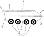
- Fig. 2 the military vehicle 2 shown in Fig. 1 is illustrated.
- the view is seen from the side.
- the vehicle includes a body 6 with a horizontally oriented top face 8 and bottom face 10.
- the bottom face 10 adjoins a rearwards inclining back face 16 and a forwards inclining front face 18 adjoining a rearwards inclining oblique face 20 that abuts on the top face 8.
- four wheels 4 are rotatably fastened in wheel suspensions.
- both the bottom face 10 and the top face 8 may have other shapes. It is e.g. possible to use a curving shape or a V-shape.
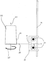
- Fig. 3 illustrates a mandrel 22 around which carbon fibre threads 28 are wound.
- the mandrel 22 rotates about a horizontal axis 24 in the theoretical centre axis of the vehicle in longitudinal direction.
- the direction of rotation 30 corresponds to the mandrel 22 being wrapped with carbon fibre threads 28.
- carbon fibre threads 28 may advantageously be wound around the mandrel 22 at both sides of the armouring material 26.
- the armouring material 26 will hereby be secured by the wound threads 28.
- the carbon fibre thread 28 is wetted with glue via passage through a gluing apparatus 32 which is disposed close to the mandrel 22.
- the carbon fibre thread 28 is unrolled from a roll 34.
- the carbon fibre thread 28 is passed around a pulley 40 before the carbon fibre thread 28 is passed in through the gluing apparatus 32.
- the gluing apparatus 32 is fastened to a slide 38 which can slide back and forth on a rail 36. Two rolls of thread 34 are disposed in the slide 38 and may rotate about each their vertical axis (not shown).
- the mandrel 22 rotates about its own longitudinal axis 24.
- the gluing apparatus 32 is fastened to the slide 38 which simultaneously with the rotation of the mandrel about its own longitudinal axis 24 is moved in parallel with the longitudinal axis 24 of the mandrel. Hereby is achieved the opportunity of covering all surfaces.
- the direction of orientation of the threads in relation to the longitudinal axis 24 of the mandrel may be controlled by the speed of the slide relative to the rotational speed of the mandrel.
- the threads 28 When the slide 38 is moving slowly relative to the rotational speed of the mandrel, the threads 28 will be oriented almost perpendicularly to the longitudinal axis 24 of the mandrel.
- the threads 28 When the slide 38 is moved rapidly relative to the rotational speed of the mandrel, the threads 28 will be oriented almost in parallel with the longitudinal axis 24 of the mandrel.
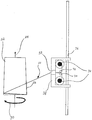
- Fig. 4 shows the embodiment shown in Fig. 3 where the slide 38 is moved in parallel with the longitudinal axis 24 of the mandrel.
- threads 28 from two thread rolls 34 which are provided on the slide 38.
- the two threads 28 are passed around each their pulley 40, 42 before the threads 28 are passed through the gluing apparatus 32.
- the body may advantageously be cured after the winding. This may e.g. occur under heating. Then the body may be drawn off the mandrel 22, after which the ends of the body may be cut off at suitable angles, so that the rear end and the front end may be closed with plates (not shown). These plates may advantageously contain carbon fibres.
- an armouring material 26 is applied during the winding process and thus integrated into the body.
- elements (not shown) of e.g. aluminium may be placed on the mandrel 22 at the areas where e.g. wheel suspensions (not shown) are to be mounted. These elements are hereby glued into the body during the winding process. Subsequently, through-holes are to be established, and the areas are to be cleaned from carbon fibres 28. The body may subsequently be coated with e.g. paint. The body will then be ready for mounting of e.g. wheel suspension, motor, gearbox and additional armouring.
Landscapes
- Engineering & Computer Science (AREA)
- Mechanical Engineering (AREA)
- General Engineering & Computer Science (AREA)
- Reinforced Plastic Materials (AREA)
- Moulding By Coating Moulds (AREA)
Description
- The present invention concerns a method for making a vehicle including a body comprising carbon fibres, where the body is wound up on a mandrel with threads wetted in glue, where the threads contain carbon fibres, where the threads wound around the mandrel are subsequently cured where, after the curing, the body is drawn off the mandrel, where the front end and rear end of the body are closed with closure elements.
- In connection with making military armoured vehicles, it is attempted to reduce the weight of the vehicle in relation to the load carrying ability of the vehicles. Low weight is necessary in order to move the vehicles by air. At the same time, good armouring is required. Conventional armoured vehicles, including road vehicles, are mainly built of armoured steel for protection and carrying ability.
- In order to reduce the self-weight simultaneously with maintaining the load carrying ability and ability of bearing armour, respectively, it is required to use materials with great strength compared to the density of the materials. For that purpose, carbon fibres have appeared to have the required material properties. Until now, the production of armoured vehicles has been based on using moulding tools corresponding to those used in the production of glass fibre boats. The production of vehicles containing carbon fibres has thus consisted in initially laying mats of carbon fibre in moulds and subsequently adding a special glue (resin/matrix), after which the materials are cured under vacuum and temperature (possibly autoclave with overpressure). This process is relatively costly due to the required use of expensive tools (including autoclave) and the manual handling. Besides, the complicated moulding tools have given rise to substantial expenses in production. Often there is used a body consisting of a number of parts which are to be assembled subsequently. Control of the tolerances of the finished product, especially on the side facing away from the moulding tool, is hereby made difficult.
-
US patent application 2005/0188831 describes a resistant tower for use in connection with a military vehicle, and a method for making such a tower. The tower has walls around which fibres are wrapped. In the patent application is mentioned that they may be carbon fibre threads. The method includes weaving fibres (impregnated with adhesive resin) around a mould. This publication describes use of carbon fibre threads in connection with the making of individual subelements, such as a tower. In connection with constructing armoured vehicles, it will be expedient to enable making the largest possible part of the vehicle in one and the same procedure. -
US patent 6,490,990 describes a method of the type described in the introduction for making a floating object. In this publication, there is thus a description of method steps where threads wetted in glue are wrapped over a mandrel and subsequently cured. There is no mentioning of finishing treatment after curing for handling the cured structure with regard adaptation to specific applications. -
US Patent 5,365,662 describes a method of the type described in the introduction. This document describes a method in which a railway coach is manufactured. The document mentions that a curing is effected and that the mandrel is supplied with a front and rear end in form of closure elements. - This document does not disclose specific form for the cut-off in order to establish the possibility of cut-offs for specific purposes. Moreover, there is no disclosure of a method for making a vehicle which is different from the railway coach.
- Especially there is no mentioning of specific methods or features in a method which is necessary for providing a vehicle suitable for military purposes.
-
WO 01/85517 A1 - This vehicle is not suitable for operating in a hostile environment with threats from weapons.
- The object of the present invention is to indicate a method for making a vehicle with low weight compared with steel or aluminium frames, with great uniformity of the final structure, with few joints and with low tool expenses and possibility of handling the cured structure with regard to adaptation to specific applications especially military purposes.
- According to the present invention this is achieved by a method of the type mentioned by way of introduction which is peculiar in that during the winding process, one or more layers of light weight ceramic and/or other armouring materials are laid in which thereby become integrated in the basic body and that mounting agents are put on the mandrel, whereafter mounting means are fitted, where mounting agents and means are cleaned from threads and glue after the winding process, where the body is subsequently surface treated.
- As the mounting agents are put on mandrel, then the mounting agents will have their positions controlled by the mandrel. Hereby it is possible to provide a large number of necessary mountings both before and after winding the body.
- The invention is advantageous because the body may achieve a high degree of armouring. This may be necessary when the vehicle is to be used for military purposes. It is possible to provide various degrees of armouring in various parts of the body by varying the number, the thickness and the nature of the applied layers of armouring materials.
- The curing may e.g. be effected by heating, e.g. in an oven.
- By a method according to the invention there is thus achieved an advantage, as the weight of the vehicle is reduced. By air transport, the weight of the vehicles will be decisive. Thus it will be possible to transport the vehicle by air, e.g. in connection with remote areas of action.
- At the same time, the method is cheaper than the traditional methods of manufacture due the much reduced tool expenses, i.a. because the curing is effected without using an autoclave for applying overpressure. Also, the need for manual handling becomes unnecessary. It is furthermore an advantage that great uniformity can be attained with regard to the final structure. It is an additional advantage that the larger part of the vehicle can be produced in one procedure. An additional advantage is achieved as prestressed fibres can be used in connection with the winding. Hereby optimal possibilities for controlling the fibre directions are achieved.
- By a method according to the present invention is achieved the possibility of adapting the body to specific applications. Advantageously, closure elements containing armouring material can be used for increasing the strength of the vehicle. It is furthermore possible subsequently to cut out areas of the body for e.g. windows, openings, doors or other devices.
- Mounting agents are put on the mandrel, whereafter mounting means are fitted, where mounting agents and means are cleaned from threads and glue after the winding process, where the body is subsequently surface treated or coated. Hereby is achieved the possibility of providing a large number of necessary mountings both before and after winding the body. Mounting means may e.g. consist of a lightweight metal frame on which means, such as wheel suspensions, can be mounted afterwards. Also, more refined devices of more complicated nature may also be provided. It is possible to produced a frame, e.g. in aluminium, which can be wound into the fibre structure.
- According to yet an embodiment, the present invention is peculiar in that after the surface treatment of the body, mounting elements may be fitted. Hereby is achieved possibility of providing a number of required devices, e.g. in the form of mounting elements, such as motor, gearbox and additional armour. This enables constructing a functional and top modern vehicle.
- The vehicle may e.g. be a military vehicle, an armoured military vehicle, a military aircraft or an armoured military aircraft. The present invention provides possibility of providing vehicles which are specifically adapted to the needs prevailing in military applications.
- The invention will now be explained below with reference to the accompanying schematic drawing, where:
- Fig. 1
- shows a schematic view of an embodiment of a military vehicle according to the invention, as seen from behind;
- Fig. 2
- shows the military vehicle shown in
Fig. 1 as seen from the side; - Fig. 3
- shows a mandrel about which a thread is wound.
Fig. 3 is seen from above; and - Fig. 4
- shows a mandrel about which two threads are wound;
Fig. 4 is seen from above. - Firstly, it is to be noted that the attached drawing only illustrates non-limiting embodiments of the invention. A number of other embodiments will be possible within the scope of the present invention. In the following description, identical or corresponding elements in the various embodiments will be provided with the same designations below.
-
Fig. 1 shows a rear view of amilitary vehicle 2. The vehicle comprises abody 6 with a decagonal cross-section, where both thetop surface 8 and thebottom surface 10 are horizontally oriented. Thebottom face 10 adjoins the obliquely extending side faces 12. At the end of the side faces 12 situated closest to thebottom face 10,wheel suspensions 14 are attached on whichwheels 4 are rotatably mounted. OnFig. 1 , only twowheels 4 are visible. It is to be emphasised that thebottom face 10 may have other shapes, including a curving shape or a V-shape. A V-shapedbottom face 10 may in some situations be preferred, because a V-shapedbottom plate 10 may deflect a pressure wave to a higher degree than e.g. ahorizontal bottom face 10. - On
Fig. 2 , themilitary vehicle 2 shown inFig. 1 is illustrated. The view is seen from the side. The vehicle includes abody 6 with a horizontally orientedtop face 8 andbottom face 10. Thebottom face 10 adjoins a rearwards inclining backface 16 and a forwards inclining front face 18 adjoining a rearwards incliningoblique face 20 that abuts on thetop face 8. At each side of thevehicle 2, fourwheels 4 are rotatably fastened in wheel suspensions. It is to be noted that both thebottom face 10 and thetop face 8 may have other shapes. It is e.g. possible to use a curving shape or a V-shape. -
Fig. 3 illustrates amandrel 22 around whichcarbon fibre threads 28 are wound. Themandrel 22 rotates about ahorizontal axis 24 in the theoretical centre axis of the vehicle in longitudinal direction. The direction ofrotation 30 corresponds to themandrel 22 being wrapped withcarbon fibre threads 28. There is provided a piece of lightweightceramic armouring material 26. It is to be noted thatcarbon fibre threads 28 may advantageously be wound around themandrel 22 at both sides of thearmouring material 26. Thearmouring material 26 will hereby be secured by thewound threads 28. Thecarbon fibre thread 28 is wetted with glue via passage through a gluingapparatus 32 which is disposed close to themandrel 22. Thecarbon fibre thread 28 is unrolled from aroll 34. Thecarbon fibre thread 28 is passed around apulley 40 before thecarbon fibre thread 28 is passed in through the gluingapparatus 32. The gluingapparatus 32 is fastened to aslide 38 which can slide back and forth on arail 36. Two rolls ofthread 34 are disposed in theslide 38 and may rotate about each their vertical axis (not shown). Themandrel 22 rotates about its ownlongitudinal axis 24. The gluingapparatus 32 is fastened to theslide 38 which simultaneously with the rotation of the mandrel about its ownlongitudinal axis 24 is moved in parallel with thelongitudinal axis 24 of the mandrel. Hereby is achieved the opportunity of covering all surfaces. In addition, the direction of orientation of the threads in relation to thelongitudinal axis 24 of the mandrel may be controlled by the speed of the slide relative to the rotational speed of the mandrel. When theslide 38 is moving slowly relative to the rotational speed of the mandrel, thethreads 28 will be oriented almost perpendicularly to thelongitudinal axis 24 of the mandrel. When theslide 38 is moved rapidly relative to the rotational speed of the mandrel, thethreads 28 will be oriented almost in parallel with thelongitudinal axis 24 of the mandrel. By varying the speed of the slide relative to the rotational speed of the mandrel, there is achieved the possibility of providing a very strong weaving withthreads 28 oriented in various directions. - It is to be emphasised that many rolls of threads can be used simultaneously. Furthermore, it is possible to place the thread rolls in a magazine located some distance from the slide in direction away from the mandrel. The slide will thus gather the threads and move them in desired direction relative to the mandrel. The threads may thus be wetted in glue and wrapped around the rotating mandrel. In that way it becomes possible to use a large number of threads at the same time, and therefore there will be many options for varying the way in which threads are wound around the mandrel.
-
Fig. 4 shows the embodiment shown inFig. 3 where theslide 38 is moved in parallel with thelongitudinal axis 24 of the mandrel. In connection with the winding, there are usedthreads 28 from two thread rolls 34 which are provided on theslide 38. The twothreads 28 are passed around each theirpulley threads 28 are passed through the gluingapparatus 32. - The body may advantageously be cured after the winding. This may e.g. occur under heating. Then the body may be drawn off the
mandrel 22, after which the ends of the body may be cut off at suitable angles, so that the rear end and the front end may be closed with plates (not shown). These plates may advantageously contain carbon fibres. - As
carbon fibres 28 alone have inferior armouring properties, anarmouring material 26 is applied during the winding process and thus integrated into the body. According to need, elements (not shown) of e.g. aluminium may be placed on themandrel 22 at the areas where e.g. wheel suspensions (not shown) are to be mounted. These elements are hereby glued into the body during the winding process. Subsequently, through-holes are to be established, and the areas are to be cleaned fromcarbon fibres 28. The body may subsequently be coated with e.g. paint. The body will then be ready for mounting of e.g. wheel suspension, motor, gearbox and additional armouring.
Claims (6)
- A method for making a vehicle (2), including a body comprising carbon fibres (28), where the body is wound up on a mandrel (22) with threads (28) wetted in glue, where the threads (28) contain carbon fibres, where the threads (28) wound around the mandrel (22) are subsequently cured, where, after the curing, the body is drawn off the mandrel (22), where the front end and rear end of the body are closed with closure elements, characterised in that during the winding process, one or more layers of light weight ceramic and/or other armouring materials (26) are laid in which thereby become integrated in the basic body and that mounting agents are put on the mandrel (22), whereafter mounting means are fitted, where mounting agents and means are cleaned from threads (28) and glue after the winding process, where the body is subsequently surface treated.
- Method according to claim 1, characterised in that after the surface treatment of the body, mounting elements are fitted.
- Method according to claim 1 or 2, characterised in that the vehicle (2) is a military vehicle.
- Method according to claim 1 or 2, characterised in that the vehicle (2) is an armoured military vehicle.
- Method according to claim 1 or 2, characterised in that the ends of the body are cut off at appropriate angles, so that the rear end and the front end may be closed with closure elements.
- Method according to claim 1 or 2, characterised in that the closure elements contain carbon fibres and armouring materials.
Priority Applications (2)
| Application Number | Priority Date | Filing Date | Title |
|---|---|---|---|
| PL07817846T PL2094468T3 (en) | 2006-10-20 | 2007-10-19 | Method for manufacturing a vehicle comprising carbon fibres |
| SI200731899A SI2094468T1 (en) | 2006-10-20 | 2007-10-19 | Method for manufacturing a vehicle comprising carbon fibres |
Applications Claiming Priority (2)
| Application Number | Priority Date | Filing Date | Title |
|---|---|---|---|
| DK200601358A DK176526B1 (en) | 2006-10-20 | 2006-10-20 | Method for producing a vessel vessel containing carbon fiber |
| PCT/DK2007/000450 WO2008064676A1 (en) | 2006-10-20 | 2007-10-19 | Method for manufacturing a vehicle comprising carbon fibre |
Publications (3)
| Publication Number | Publication Date |
|---|---|
| EP2094468A1 EP2094468A1 (en) | 2009-09-02 |
| EP2094468A4 EP2094468A4 (en) | 2012-05-02 |
| EP2094468B1 true EP2094468B1 (en) | 2016-12-14 |
Family
ID=39363776
Family Applications (1)
| Application Number | Title | Priority Date | Filing Date |
|---|---|---|---|
| EP07817846.4A Active EP2094468B1 (en) | 2006-10-20 | 2007-10-19 | Method for manufacturing a vehicle comprising carbon fibres |
Country Status (10)
| Country | Link |
|---|---|
| US (1) | US8025753B2 (en) |
| EP (1) | EP2094468B1 (en) |
| CA (1) | CA2666990C (en) |
| DK (2) | DK176526B1 (en) |
| ES (1) | ES2618479T3 (en) |
| HU (1) | HUE032041T2 (en) |
| PL (1) | PL2094468T3 (en) |
| PT (1) | PT2094468T (en) |
| SI (1) | SI2094468T1 (en) |
| WO (1) | WO2008064676A1 (en) |
Families Citing this family (1)
| Publication number | Priority date | Publication date | Assignee | Title |
|---|---|---|---|---|
| CN109592462A (en) * | 2018-12-11 | 2019-04-09 | 湖南烯瑞自动化设备有限公司 | A kind of carbon fiber cloth-rolling device |
Family Cites Families (22)
| Publication number | Priority date | Publication date | Assignee | Title |
|---|---|---|---|---|
| US3655468A (en) * | 1964-08-06 | 1972-04-11 | Owens Corning Fiberglass Corp | Fluid-handling constructions, apparatus and methods of production |
| US3449484A (en) | 1966-10-05 | 1969-06-10 | Koppers Co Inc | Method for forming filament reinforced resin shells of non-uniform cross section |
| US3783060A (en) * | 1970-07-27 | 1974-01-01 | Goldsworthy Eng Inc | Method and apparatus for making filament reinforced storage vessels |
| GB2028708B (en) * | 1978-04-19 | 1982-06-30 | Graham Smith J | Glass gibre vehicle body shells |
| FR2439117A1 (en) | 1978-10-16 | 1980-05-16 | Venissieux Atel | Central frame for articulated vehicles - uses slide bearing positioning to compensate for bending momentum |
| DE2921854C1 (en) | 1979-05-30 | 1990-11-15 | Thyssen Ind Ag Maschb | Process for producing armor made of multi-layer steel |
| GB2156272A (en) * | 1984-03-17 | 1985-10-09 | Michael Sacks | Protective shields |
| NL8601650A (en) * | 1986-06-24 | 1988-01-18 | Fokker Special Products | ARMOR PLATE. |
| ATE149913T1 (en) * | 1992-07-10 | 1997-03-15 | Inventio Ag | METHOD FOR THE INTEGRAL PRODUCTION OF AN INTERIOR FOR A CAR BODY |
| US5533781A (en) | 1994-06-20 | 1996-07-09 | O'gara-Hess & Eisenhardt Armoring Co., Inc. | Armoring assembly |
| NL1000598C2 (en) * | 1995-06-20 | 1996-12-23 | Dsm Nv | Anti-ballistic molded part and a method of manufacturing the molded part. |
| FR2774325B1 (en) | 1998-02-05 | 2000-03-17 | Alexandre Hamlyn | METHOD FOR MANUFACTURING FLOATING BODIES AND MANDREL BOATS AND APPARATUSES FOR SUCH MANUFACTURE |
| EP0967453A1 (en) * | 1998-06-25 | 1999-12-29 | Armortec Incorporated | Flexible, impact-resistant materials |
| ES2212446T3 (en) | 1998-10-14 | 2004-07-16 | Peter Goedtke | PROTECTIVE SHIELD. |
| US6537654B1 (en) | 1999-11-04 | 2003-03-25 | Sgl Technik Gmbh | Protection products and armored products made of fiber-reinforced composite material with ceramic matrix |
| US6361635B1 (en) * | 2000-01-10 | 2002-03-26 | Shade, Inc. | Method of fabricating a filament wound vessel |
| FR2808756B1 (en) * | 2000-05-12 | 2004-02-13 | Mediterranee Const Ind | PROCESS FOR PREPARING A COMPOSITE MATERIAL STRUCTURE, PARTICULARLY FOR RAIL VEHICLES |
| US7101435B2 (en) * | 2003-05-30 | 2006-09-05 | Micron Technology, Inc. | Methods for epitaxial silicon growth |
| US20050188831A1 (en) | 2003-07-11 | 2005-09-01 | Us Global Nanospace, Inc. | Ballistic resistant turret and method of making same |
| DE102004019400A1 (en) | 2004-04-19 | 2005-11-03 | Hugo Siebert | Lightweight armoured mesh has carbon fibre weave coated with metal matrix compound and fitted with optional ceramic plates |
| US7261786B2 (en) * | 2004-09-16 | 2007-08-28 | The Boeing Company | Filament wound crew rest enclosure structure |
| US7096814B1 (en) | 2005-01-04 | 2006-08-29 | Webb Douglas C | Variable buoyancy device |
-
2006
- 2006-10-20 DK DK200601358A patent/DK176526B1/en not_active IP Right Cessation
-
2007
- 2007-10-19 EP EP07817846.4A patent/EP2094468B1/en active Active
- 2007-10-19 WO PCT/DK2007/000450 patent/WO2008064676A1/en not_active Ceased
- 2007-10-19 SI SI200731899A patent/SI2094468T1/en unknown
- 2007-10-19 PL PL07817846T patent/PL2094468T3/en unknown
- 2007-10-19 DK DK07817846.4T patent/DK2094468T3/en active
- 2007-10-19 HU HUE07817846A patent/HUE032041T2/en unknown
- 2007-10-19 CA CA2666990A patent/CA2666990C/en not_active Expired - Fee Related
- 2007-10-19 ES ES07817846.4T patent/ES2618479T3/en active Active
- 2007-10-19 US US12/311,957 patent/US8025753B2/en active Active
- 2007-10-19 PT PT78178464T patent/PT2094468T/en unknown
Non-Patent Citations (1)
| Title |
|---|
| OGORKIEWICZ R M: "ARMOURED VEHICLES OF COMPOSITE MATERIALS", INTERNATIONAL DEFENSE REVIEW, JANE'S INFORMATION GROUP, COULSDON, SURREY, GB, vol. 22, no. 7, 1 July 1989 (1989-07-01), pages 969 - 970, XP000068343, ISSN: 0020-6512 * |
Also Published As
| Publication number | Publication date |
|---|---|
| US8025753B2 (en) | 2011-09-27 |
| US20100024965A1 (en) | 2010-02-04 |
| SI2094468T1 (en) | 2017-07-31 |
| HUE032041T2 (en) | 2017-08-28 |
| DK176526B1 (en) | 2008-07-14 |
| EP2094468A4 (en) | 2012-05-02 |
| ES2618479T3 (en) | 2017-06-21 |
| PL2094468T3 (en) | 2017-06-30 |
| CA2666990A1 (en) | 2008-06-05 |
| CA2666990C (en) | 2015-02-03 |
| DK2094468T3 (en) | 2017-03-20 |
| EP2094468A1 (en) | 2009-09-02 |
| WO2008064676A1 (en) | 2008-06-05 |
| DK200601358A (en) | 2008-04-21 |
| PT2094468T (en) | 2017-03-15 |
Similar Documents
| Publication | Publication Date | Title |
|---|---|---|
| US20080169380A1 (en) | Composite aircraft window frame | |
| EP2813352B1 (en) | Method of post-cure processing of composite core | |
| EP2772344B1 (en) | System and method of manufacturing composite core | |
| US20050236736A1 (en) | Composite product and forming system | |
| EP1798428A1 (en) | Braided composite part | |
| WO2007071879A2 (en) | Method for manufacturing an aircraft fuselage in composite material | |
| EP1993808A2 (en) | Process for the production of a three-dimensionally shaped sandwich structure | |
| DE102010031639A1 (en) | Composite component and method for producing a composite component | |
| US10265937B2 (en) | Method and apparatus for manufacturing a sandwich component | |
| EP4247620A1 (en) | Automated manufacture of 3d objects from composite material | |
| US20200148278A1 (en) | Vehicle External Surface Component and Method for Producing a Vehicle External Surface Component | |
| DE102011082087A1 (en) | Core material for e.g. aircraft wing, has honeycomb webs that are filled in cavities between fiber strands of filler provided in metal plates, through bonding agent | |
| DK2094468T3 (en) | Armored vehicle | |
| DE102011004984A1 (en) | Component for rail vehicles | |
| US20110017384A1 (en) | Composite fuselage for vehicles | |
| EP2772346B1 (en) | Method of manufacturing a composite core | |
| DE102013226792A1 (en) | A method for acoustic and / or fluidic perforation of a component made of a fiber composite plastic | |
| DK178107B1 (en) | Method for manufacturing a filament-wound structure and use thereof | |
| DE102011011354B4 (en) | Composite component of a vehicle and method for its production | |
| CN118991201A (en) | Co-curable and co-curable UV/visible light release resistant ply applications for composite components | |
| DE102016211370A1 (en) | Method for producing a vehicle structure and vehicle structure | |
| JPH04316810A (en) | Method and equipment to assemble sheet of composite material | |
| CA2844136A1 (en) | System and method of manufacturing composite core |
Legal Events
| Date | Code | Title | Description |
|---|---|---|---|
| PUAI | Public reference made under article 153(3) epc to a published international application that has entered the european phase |
Free format text: ORIGINAL CODE: 0009012 |
|
| 17P | Request for examination filed |
Effective date: 20090506 |
|
| AK | Designated contracting states |
Kind code of ref document: A1 Designated state(s): AT BE BG CH CY CZ DE DK EE ES FI FR GB GR HU IE IS IT LI LT LU LV MC MT NL PL PT RO SE SI SK TR |
|
| DAX | Request for extension of the european patent (deleted) | ||
| A4 | Supplementary search report drawn up and despatched |
Effective date: 20120402 |
|
| RIC1 | Information provided on ipc code assigned before grant |
Ipc: F41H 7/00 20060101ALI20120327BHEP Ipc: B63B 5/24 20060101ALI20120327BHEP Ipc: B29C 53/66 20060101AFI20120327BHEP |
|
| 17Q | First examination report despatched |
Effective date: 20121109 |
|
| GRAP | Despatch of communication of intention to grant a patent |
Free format text: ORIGINAL CODE: EPIDOSNIGR1 |
|
| INTG | Intention to grant announced |
Effective date: 20160706 |
|
| GRAS | Grant fee paid |
Free format text: ORIGINAL CODE: EPIDOSNIGR3 |
|
| GRAA | (expected) grant |
Free format text: ORIGINAL CODE: 0009210 |
|
| AK | Designated contracting states |
Kind code of ref document: B1 Designated state(s): AT BE BG CH CY CZ DE DK EE ES FI FR GB GR HU IE IS IT LI LT LU LV MC MT NL PL PT RO SE SI SK TR |
|
| REG | Reference to a national code |
Ref country code: GB Ref legal event code: FG4D |
|
| REG | Reference to a national code |
Ref country code: CH Ref legal event code: EP |
|
| REG | Reference to a national code |
Ref country code: IE Ref legal event code: FG4D |
|
| REG | Reference to a national code |
Ref country code: AT Ref legal event code: REF Ref document number: 853183 Country of ref document: AT Kind code of ref document: T Effective date: 20170115 |
|
| REG | Reference to a national code |
Ref country code: DE Ref legal event code: R096 Ref document number: 602007049162 Country of ref document: DE |
|
| PG25 | Lapsed in a contracting state [announced via postgrant information from national office to epo] |
Ref country code: LV Free format text: LAPSE BECAUSE OF FAILURE TO SUBMIT A TRANSLATION OF THE DESCRIPTION OR TO PAY THE FEE WITHIN THE PRESCRIBED TIME-LIMIT Effective date: 20161214 |
|
| REG | Reference to a national code |
Ref country code: CH Ref legal event code: NV Representative=s name: FIAMMENGHI-FIAMMENGHI, CH Ref country code: PT Ref legal event code: SC4A Ref document number: 2094468 Country of ref document: PT Date of ref document: 20170315 Kind code of ref document: T Free format text: AVAILABILITY OF NATIONAL TRANSLATION Effective date: 20170309 |
|
| REG | Reference to a national code |
Ref country code: DK Ref legal event code: T3 Effective date: 20170314 |
|
| REG | Reference to a national code |
Ref country code: SE Ref legal event code: TRGR |
|
| REG | Reference to a national code |
Ref country code: NL Ref legal event code: FP |
|
| REG | Reference to a national code |
Ref country code: LT Ref legal event code: MG4D |
|
| PG25 | Lapsed in a contracting state [announced via postgrant information from national office to epo] |
Ref country code: LT Free format text: LAPSE BECAUSE OF FAILURE TO SUBMIT A TRANSLATION OF THE DESCRIPTION OR TO PAY THE FEE WITHIN THE PRESCRIBED TIME-LIMIT Effective date: 20161214 |
|
| REG | Reference to a national code |
Ref country code: ES Ref legal event code: FG2A Ref document number: 2618479 Country of ref document: ES Kind code of ref document: T3 Effective date: 20170621 |
|
| PG25 | Lapsed in a contracting state [announced via postgrant information from national office to epo] |
Ref country code: EE Free format text: LAPSE BECAUSE OF FAILURE TO SUBMIT A TRANSLATION OF THE DESCRIPTION OR TO PAY THE FEE WITHIN THE PRESCRIBED TIME-LIMIT Effective date: 20161214 Ref country code: RO Free format text: LAPSE BECAUSE OF FAILURE TO SUBMIT A TRANSLATION OF THE DESCRIPTION OR TO PAY THE FEE WITHIN THE PRESCRIBED TIME-LIMIT Effective date: 20161214 Ref country code: IS Free format text: LAPSE BECAUSE OF FAILURE TO SUBMIT A TRANSLATION OF THE DESCRIPTION OR TO PAY THE FEE WITHIN THE PRESCRIBED TIME-LIMIT Effective date: 20170414 |
|
| REG | Reference to a national code |
Ref country code: GR Ref legal event code: EP Ref document number: 20170400734 Country of ref document: GR Effective date: 20170804 |
|
| REG | Reference to a national code |
Ref country code: HU Ref legal event code: AG4A Ref document number: E032041 Country of ref document: HU |
|
| PG25 | Lapsed in a contracting state [announced via postgrant information from national office to epo] |
Ref country code: BG Free format text: LAPSE BECAUSE OF FAILURE TO SUBMIT A TRANSLATION OF THE DESCRIPTION OR TO PAY THE FEE WITHIN THE PRESCRIBED TIME-LIMIT Effective date: 20170314 |
|
| REG | Reference to a national code |
Ref country code: SK Ref legal event code: T3 Ref document number: E 23686 Country of ref document: SK |
|
| REG | Reference to a national code |
Ref country code: DE Ref legal event code: R097 Ref document number: 602007049162 Country of ref document: DE |
|
| PLBE | No opposition filed within time limit |
Free format text: ORIGINAL CODE: 0009261 |
|
| STAA | Information on the status of an ep patent application or granted ep patent |
Free format text: STATUS: NO OPPOSITION FILED WITHIN TIME LIMIT |
|
| 26N | No opposition filed |
Effective date: 20170915 |
|
| REG | Reference to a national code |
Ref country code: FR Ref legal event code: PLFP Year of fee payment: 11 |
|
| PG25 | Lapsed in a contracting state [announced via postgrant information from national office to epo] |
Ref country code: MC Free format text: LAPSE BECAUSE OF FAILURE TO SUBMIT A TRANSLATION OF THE DESCRIPTION OR TO PAY THE FEE WITHIN THE PRESCRIBED TIME-LIMIT Effective date: 20161214 |
|
| REG | Reference to a national code |
Ref country code: DE Ref legal event code: R081 Ref document number: 602007049162 Country of ref document: DE Owner name: DRS SUSTAINMENT SYSTEMS, INC., ST. LOUIS, US Free format text: FORMER OWNER: FALCK SCHMIDT DEFENCE SYSTEMS A/S, ODENSE, DK |
|
| REG | Reference to a national code |
Ref country code: CH Ref legal event code: PUE Owner name: DRS SUSTAINMENT SYSTEMS, INC., US Free format text: FORMER OWNER: FALCK SCHMIDT DEFENCE SYSTEMS A/S, DK |
|
| REG | Reference to a national code |
Ref country code: HU Ref legal event code: FH1C Free format text: FORMER REPRESENTATIVE(S): DANUBIA SZABADALMI ES JOGI IRODA KFT., HU Representative=s name: DANUBIA SZABADALMI ES JOGI IRODA KFT., HU Ref country code: HU Ref legal event code: GB9C Owner name: DRS SUSTAINMENT SYSTEMS, INC., US Free format text: FORMER OWNER(S): FALCK SCHMIDT DEFENCE SYSTEMS A/S, DK |
|
| REG | Reference to a national code |
Ref country code: ES Ref legal event code: PC2A Effective date: 20180725 Ref country code: ES Ref legal event code: PC2A Owner name: DRS SUSTAINMENT SYSTEMS INC. Effective date: 20180725 |
|
| REG | Reference to a national code |
Ref country code: GB Ref legal event code: 732E Free format text: REGISTERED BETWEEN 20180709 AND 20180711 |
|
| REG | Reference to a national code |
Ref country code: LU Ref legal event code: PD Owner name: DRS SUSTAINMENT SYSTEMS, INC.; US Free format text: FORMER OWNER: FALCK SCHMIDT DEFENCE SYSTEMS A/S Effective date: 20180723 |
|
| REG | Reference to a national code |
Ref country code: BE Ref legal event code: FP Effective date: 20170313 Ref country code: BE Ref legal event code: PD Owner name: DRS SUSTAINMENT SYSTEMS, INC.; US Free format text: DETAILS ASSIGNMENT: CHANGE OF OWNER(S), CESSION; FORMER OWNER NAME: FALCK SCHMIDT DEFENCE SYSTEMS A/S Effective date: 20180628 |
|
| REG | Reference to a national code |
Ref country code: FR Ref legal event code: PLFP Year of fee payment: 12 |
|
| PG25 | Lapsed in a contracting state [announced via postgrant information from national office to epo] |
Ref country code: MT Free format text: LAPSE BECAUSE OF NON-PAYMENT OF DUE FEES Effective date: 20171019 |
|
| REG | Reference to a national code |
Ref country code: SI Ref legal event code: SP73 Owner name: DRS SUSTAINMENT SYSTEMS, INC.; US Effective date: 20180807 |
|
| REG | Reference to a national code |
Ref country code: NL Ref legal event code: PD Owner name: DRS SUSTAINMENT SYSTEMS, INC.; US Free format text: DETAILS ASSIGNMENT: CHANGE OF OWNER(S), ASSIGNMENT; FORMER OWNER NAME: FALCK SCHMIDT DEFENCE SYSTEMS A/S Effective date: 20180727 |
|
| REG | Reference to a national code |
Ref country code: AT Ref legal event code: PC Ref document number: 853183 Country of ref document: AT Kind code of ref document: T Owner name: DRS SUSTAINMENT SYSTEMS, INC., US Effective date: 20180831 |
|
| REG | Reference to a national code |
Ref country code: FR Ref legal event code: TP Owner name: DRS SUSTAINMENT SYSTEMS, INC., US Effective date: 20181105 |
|
| REG | Reference to a national code |
Ref country code: SK Ref legal event code: PC4A Ref document number: E 23686 Country of ref document: SK Owner name: DRS SUSTAINMENT SYSTEMS, INC., ST. LOUIS, MO, US Free format text: FORMER OWNER: FALCK SCHMIDT DEFENCE SYSTEMS A/S, ODENSE C, DK Effective date: 20190227 |
|
| PG25 | Lapsed in a contracting state [announced via postgrant information from national office to epo] |
Ref country code: CY Free format text: LAPSE BECAUSE OF NON-PAYMENT OF DUE FEES Effective date: 20161214 |
|
| REG | Reference to a national code |
Ref country code: AT Ref legal event code: UEP Ref document number: 853183 Country of ref document: AT Kind code of ref document: T Effective date: 20161214 |
|
| PGFP | Annual fee paid to national office [announced via postgrant information from national office to epo] |
Ref country code: FR Payment date: 20210913 Year of fee payment: 15 Ref country code: CZ Payment date: 20210929 Year of fee payment: 15 Ref country code: CH Payment date: 20210928 Year of fee payment: 15 Ref country code: IT Payment date: 20210910 Year of fee payment: 15 Ref country code: IE Payment date: 20210923 Year of fee payment: 15 Ref country code: NL Payment date: 20210928 Year of fee payment: 15 |
|
| PGFP | Annual fee paid to national office [announced via postgrant information from national office to epo] |
Ref country code: BE Payment date: 20210916 Year of fee payment: 15 Ref country code: GR Payment date: 20210914 Year of fee payment: 15 Ref country code: PL Payment date: 20210915 Year of fee payment: 15 Ref country code: SK Payment date: 20210914 Year of fee payment: 15 Ref country code: SE Payment date: 20210929 Year of fee payment: 15 Ref country code: GB Payment date: 20210907 Year of fee payment: 15 |
|
| PGFP | Annual fee paid to national office [announced via postgrant information from national office to epo] |
Ref country code: TR Payment date: 20211013 Year of fee payment: 15 Ref country code: PT Payment date: 20211019 Year of fee payment: 15 Ref country code: AT Payment date: 20210928 Year of fee payment: 15 Ref country code: DE Payment date: 20210908 Year of fee payment: 15 Ref country code: LU Payment date: 20211011 Year of fee payment: 15 Ref country code: FI Payment date: 20211011 Year of fee payment: 15 Ref country code: DK Payment date: 20211012 Year of fee payment: 15 Ref country code: ES Payment date: 20211108 Year of fee payment: 15 |
|
| PGFP | Annual fee paid to national office [announced via postgrant information from national office to epo] |
Ref country code: SI Payment date: 20210917 Year of fee payment: 15 Ref country code: HU Payment date: 20210920 Year of fee payment: 15 |
|
| REG | Reference to a national code |
Ref country code: DE Ref legal event code: R119 Ref document number: 602007049162 Country of ref document: DE |
|
| REG | Reference to a national code |
Ref country code: DK Ref legal event code: EBP Effective date: 20221031 |
|
| REG | Reference to a national code |
Ref country code: SE Ref legal event code: EUG |
|
| REG | Reference to a national code |
Ref country code: CH Ref legal event code: PL Ref country code: SK Ref legal event code: MM4A Ref document number: E 23686 Country of ref document: SK Effective date: 20221019 |
|
| REG | Reference to a national code |
Ref country code: NL Ref legal event code: MM Effective date: 20221101 |
|
| REG | Reference to a national code |
Ref country code: AT Ref legal event code: MM01 Ref document number: 853183 Country of ref document: AT Kind code of ref document: T Effective date: 20221019 |
|
| REG | Reference to a national code |
Ref country code: BE Ref legal event code: MM Effective date: 20221031 |
|
| GBPC | Gb: european patent ceased through non-payment of renewal fee |
Effective date: 20221019 |
|
| PG25 | Lapsed in a contracting state [announced via postgrant information from national office to epo] |
Ref country code: LU Free format text: LAPSE BECAUSE OF NON-PAYMENT OF DUE FEES Effective date: 20221019 |
|
| PG25 | Lapsed in a contracting state [announced via postgrant information from national office to epo] |
Ref country code: PT Free format text: LAPSE BECAUSE OF NON-PAYMENT OF DUE FEES Effective date: 20230419 Ref country code: NL Free format text: LAPSE BECAUSE OF NON-PAYMENT OF DUE FEES Effective date: 20221101 Ref country code: LI Free format text: LAPSE BECAUSE OF NON-PAYMENT OF DUE FEES Effective date: 20221031 Ref country code: HU Free format text: LAPSE BECAUSE OF NON-PAYMENT OF DUE FEES Effective date: 20221020 Ref country code: FR Free format text: LAPSE BECAUSE OF NON-PAYMENT OF DUE FEES Effective date: 20221031 Ref country code: DE Free format text: LAPSE BECAUSE OF NON-PAYMENT OF DUE FEES Effective date: 20230503 Ref country code: CZ Free format text: LAPSE BECAUSE OF NON-PAYMENT OF DUE FEES Effective date: 20221019 Ref country code: CH Free format text: LAPSE BECAUSE OF NON-PAYMENT OF DUE FEES Effective date: 20221031 Ref country code: AT Free format text: LAPSE BECAUSE OF NON-PAYMENT OF DUE FEES Effective date: 20221019 |
|
| REG | Reference to a national code |
Ref country code: SI Ref legal event code: KO00 Effective date: 20230630 |
|
| PG25 | Lapsed in a contracting state [announced via postgrant information from national office to epo] |
Ref country code: SK Free format text: LAPSE BECAUSE OF NON-PAYMENT OF DUE FEES Effective date: 20221019 Ref country code: SI Free format text: LAPSE BECAUSE OF NON-PAYMENT OF DUE FEES Effective date: 20221020 Ref country code: SE Free format text: LAPSE BECAUSE OF NON-PAYMENT OF DUE FEES Effective date: 20221020 Ref country code: GR Free format text: LAPSE BECAUSE OF NON-PAYMENT OF DUE FEES Effective date: 20230508 |
|
| PG25 | Lapsed in a contracting state [announced via postgrant information from national office to epo] |
Ref country code: BE Free format text: LAPSE BECAUSE OF NON-PAYMENT OF DUE FEES Effective date: 20221031 |
|
| PG25 | Lapsed in a contracting state [announced via postgrant information from national office to epo] |
Ref country code: IT Free format text: LAPSE BECAUSE OF NON-PAYMENT OF DUE FEES Effective date: 20221019 Ref country code: IE Free format text: LAPSE BECAUSE OF NON-PAYMENT OF DUE FEES Effective date: 20221019 Ref country code: GB Free format text: LAPSE BECAUSE OF NON-PAYMENT OF DUE FEES Effective date: 20221019 Ref country code: DK Free format text: LAPSE BECAUSE OF NON-PAYMENT OF DUE FEES Effective date: 20221031 |
|
| REG | Reference to a national code |
Ref country code: ES Ref legal event code: FD2A Effective date: 20231201 |
|
| PG25 | Lapsed in a contracting state [announced via postgrant information from national office to epo] |
Ref country code: ES Free format text: LAPSE BECAUSE OF NON-PAYMENT OF DUE FEES Effective date: 20221020 |
|
| PG25 | Lapsed in a contracting state [announced via postgrant information from national office to epo] |
Ref country code: ES Free format text: LAPSE BECAUSE OF NON-PAYMENT OF DUE FEES Effective date: 20221020 |
|
| PG25 | Lapsed in a contracting state [announced via postgrant information from national office to epo] |
Ref country code: FI Free format text: LAPSE BECAUSE OF NON-PAYMENT OF DUE FEES Effective date: 20221019 |
|
| PG25 | Lapsed in a contracting state [announced via postgrant information from national office to epo] |
Ref country code: PL Free format text: LAPSE BECAUSE OF NON-PAYMENT OF DUE FEES Effective date: 20221019 |