EP2094024B1 - Processing method and system for realizing the configuring of network element in multi-standard communication system - Google Patents
Processing method and system for realizing the configuring of network element in multi-standard communication system Download PDFInfo
- Publication number
- EP2094024B1 EP2094024B1 EP07816894.5A EP07816894A EP2094024B1 EP 2094024 B1 EP2094024 B1 EP 2094024B1 EP 07816894 A EP07816894 A EP 07816894A EP 2094024 B1 EP2094024 B1 EP 2094024B1
- Authority
- EP
- European Patent Office
- Prior art keywords
- multimode
- configuration
- information
- base station
- module
- Prior art date
- Legal status (The legal status is an assumption and is not a legal conclusion. Google has not performed a legal analysis and makes no representation as to the accuracy of the status listed.)
- Not-in-force
Links
- 238000004891 communication Methods 0.000 title description 40
- 238000003672 processing method Methods 0.000 title 1
- 230000004044 response Effects 0.000 description 60
- 230000005540 biological transmission Effects 0.000 description 17
- 238000000034 method Methods 0.000 description 9
- 230000001960 triggered effect Effects 0.000 description 8
- 230000007774 longterm Effects 0.000 description 7
- 230000003993 interaction Effects 0.000 description 4
- 238000010295 mobile communication Methods 0.000 description 4
- 238000001514 detection method Methods 0.000 description 3
- 230000000694 effects Effects 0.000 description 2
- 230000006870 function Effects 0.000 description 2
- 238000012986 modification Methods 0.000 description 2
- 230000004048 modification Effects 0.000 description 2
- 238000011161 development Methods 0.000 description 1
- 238000005516 engineering process Methods 0.000 description 1
- 238000012423 maintenance Methods 0.000 description 1
Images




Classifications
-
- H—ELECTRICITY
- H04—ELECTRIC COMMUNICATION TECHNIQUE
- H04W—WIRELESS COMMUNICATION NETWORKS
- H04W24/00—Supervisory, monitoring or testing arrangements
- H04W24/02—Arrangements for optimising operational condition
-
- H—ELECTRICITY
- H04—ELECTRIC COMMUNICATION TECHNIQUE
- H04L—TRANSMISSION OF DIGITAL INFORMATION, e.g. TELEGRAPHIC COMMUNICATION
- H04L41/00—Arrangements for maintenance, administration or management of data switching networks, e.g. of packet switching networks
- H04L41/02—Standardisation; Integration
- H04L41/022—Multivendor or multi-standard integration
-
- H—ELECTRICITY
- H04—ELECTRIC COMMUNICATION TECHNIQUE
- H04L—TRANSMISSION OF DIGITAL INFORMATION, e.g. TELEGRAPHIC COMMUNICATION
- H04L41/00—Arrangements for maintenance, administration or management of data switching networks, e.g. of packet switching networks
- H04L41/08—Configuration management of networks or network elements
- H04L41/0803—Configuration setting
- H04L41/0813—Configuration setting characterised by the conditions triggering a change of settings
- H04L41/082—Configuration setting characterised by the conditions triggering a change of settings the condition being updates or upgrades of network functionality
-
- H—ELECTRICITY
- H04—ELECTRIC COMMUNICATION TECHNIQUE
- H04L—TRANSMISSION OF DIGITAL INFORMATION, e.g. TELEGRAPHIC COMMUNICATION
- H04L41/00—Arrangements for maintenance, administration or management of data switching networks, e.g. of packet switching networks
- H04L41/08—Configuration management of networks or network elements
- H04L41/085—Retrieval of network configuration; Tracking network configuration history
- H04L41/0853—Retrieval of network configuration; Tracking network configuration history by actively collecting configuration information or by backing up configuration information
-
- H—ELECTRICITY
- H04—ELECTRIC COMMUNICATION TECHNIQUE
- H04W—WIRELESS COMMUNICATION NETWORKS
- H04W88/00—Devices specially adapted for wireless communication networks, e.g. terminals, base stations or access point devices
- H04W88/08—Access point devices
- H04W88/10—Access point devices adapted for operation in multiple networks, e.g. multi-mode access points
Definitions
- the present invention relates to the radio communication industry and particularly to a method and system for network element (NE) configuration in a multimode communication system.
- NE network element
- RATs radio access technologies
- GSM global system for mobile communications
- WCDMA wideband code division multiple access
- WiMAX world interoperability for microwave access
- LTE long term evolution
- AIE air interface evolution
- CDMA code division multiple access 2000.
- BTS base transceiver station
- NodeB base transceiver station
- WiMAX long term evolution
- AIE air interface evolution
- CDMA code division multiple access 2000.
- BTS base transceiver station
- NodeB in WCDMA named as base station in WiMAX
- eNodeB LTE
- each base station operates as an individual equipment node.
- these base stations are likely to coexist within one node and share part of the node resources, such as the backplane bus, CPU, memory of the node and even some boards of the node.
- within one node includes the physical expansion of the equipment node, for instance, capacity expansion by cascade of shelves.
- a base station which supports multiple RATs is named a multimode base station hereafter.
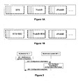
- a multimode base station can be deployed as in Figure 1A .
- a multimode base station can share some physical resources, different RAT-enabled base stations within a multimode base station may possess features different from a single-mode base station.
- a GSM base station in a multimode base station may possess some functions of a GSM base station controller (BSC). This means the GSM base station is an enhanced BTS+BSC station.
- BSC GSM base station controller
- a NodeB in a multimode base station may also be an enhanced WCDMA station, for instance, it may possess the functions of a radio network controller (RNC).
- RNC radio network controller
- An enhanced multimode base station is shown in Figure 1B .
- WO 2005/039210 A1 describes a system and method for achieving interoperability between telecommunication servers such as Mobile Switching Centers (MSCs) in a mobile communication network by automatically distributing capability and configuration information between the MSCs.
- MSCs Mobile Switching Centers
- the started-up MSC automatically sends its capabilities and configuration information to its neighboring MSCs.
- US 2003/208579 A1 describes a method and a system for updating software configuration of line-replaceable unit (LRU) computers in a restricted architecture network such as an in-flight entertainment system.
- LRU line-replaceable unit
- WO02/30141 A1 discloses multimode BTSs with dynamic channel allocation and standard selection.
- the launch of multimode base stations brings the concept of a multimode communication system, which is a system that supports multiple modes. This raises new requirements on the operation and maintenance (O&M) of NEs in a multimode communication system. Because all the current O&M actions are based on single-mode NEs, the requirement on O&M for NEs in a multimode communication system may not be satisfied.
- O&M operation and maintenance
- the present invention discloses a method and system for NE configuration in a multimode communication system.
- a method for NE configuration in a multimode communication system is a system that supports multiple modes, the mode is at least one of global system for mobile, GSM, wideband code division multiple access,WCDMA, world interoperability for microwave access, WiMAX, long term evolution, LTE, air interface evolution, AIE, and code division multiple access, CDMA.
- a method for NE configuration in a multimode communication system is a system that supports multiple modes, the mode is at least one of global system for mobile, GSM, wideband code division multiple access,WCDMA, world interoperability for microwave access, WiMAX, long term evolution, LTE, air interface evolution, AIE, and code division multiple access, CDMA, which includes: by a multimode system NE, collecting information according to a preset rule and reporting the collected information to another multimode NE in the multimode communication system determining, by the multimode NE receiving the collected information, that configuration update is needed according to the collected information and a preset configuration policy; updating, by the multimode NE, configuration information of different modes dynamically according to the received information, wherein the multimode NE and multimode system NE support at least two different modes in a radio access network.
- a method for NE configuration in a multimode communication system is a system that supports multiple modes, the mode is at least one of global system for mobile, GSM, wideband code division multiple access,WCDMA, world interoperability for microwave access, WiMAX, long term evolution, LTE, air interface evolution, AIE, and code division multiple access, CDMA, which includes: by a multimode system NE, collecting information according to a preset rule and reporting the collected information to an O&M module; sending, by the O&M module, configuration information to the multimode system NE according to the received information; updating, by the multimode system NE, the configuration according to the received configuration information.
- GSM global system for mobile
- WCDMA wideband code division multiple access
- WiMAX world interoperability for microwave access
- WiMAX long term evolution
- LTE long term evolution
- AIE air interface evolution
- CDMA code division multiple access
- the multimode system NE that receives the configuration information is the multimode system NE that collects information, or a combination of the multimode system NE collecting information and a multimode system NE other than the one colleting information, wherein the multimode system NEs support at least two different modes in a radio access network.
- a system for NE configuration in a multimode communication system is a system that supports multiple modes, the mode is at least one of global system for mobile, GSM, wideband code division multiple access, WCDMA, world interoperability for microwave access, WiMAX, long term evolution, LTE, air interface evolution, AIE, and code division multiple access, CDMA, which includes at least a first multimode NE and a second multimode system NE.
- the first multimode NE updates configuration information of different modes dynamically and sends configuration information to the second multimode system NE; the second multimode system NE updates its configuration according to the received configuration information, wherein the first multimode NE and second multimode system NE support at least two different modes in a radio access network.
- a system for NE configuration in a multimode communication system includes at least a first multimode system NE and a second multimode NE.
- the multimode communication system is a system that supports multiple modes, the mode is at least one of global system for mobile, GSM, wideband code division multiple access, WCDMA, world interoperability for microwave access, WiMAX, long term evolution, LTE, air interface evolution, AIE, and code division multiple access, CDMA.
- the first multimode system NE collects information according to a preset rule and reports the collected information to the second multimode NE; the second multimode NE updates configuration information of different modes dynamically according to the collected information, wherein the first multimode NE and second multimode system NE support at least two different modes in a radio access network.
- a system for NE configuration in a multimode communication system is a system that supports multiple modes, the mode is at least one of global system for mobile, GSM, wideband code division multiple access, WCDMA, world interoperability for microwave access, WiMAX, long term evolution, LTE, air interface evolution, AlE, and code division multiple access, CDMA, which includes at least an O&M module and one or more multimode system NEs.
- the multimode system NE collects information according to a preset rule and reports the collected information to the O&M module; the O&M module sends configuration information to the multimode system NE according to the received collected information; the multimode system NE updates its configuration according to the received configuration information; the multimode system NE receiving the configuration information is the multimode system NE that collects information, or a multimode system NE other than the one collecting information, or a combination of the two, wherein the multimode system NEs support at least two different modes in a radio access network.
- a multimode system NE after a multimode system NE changes configuration information, it sends a configuration update request to other multimode system NEs.
- the NE may send configuration information to the other multimode system NEs directly or via an O&M module.
- This enables a multimode communication system to carry out more rational configuration in the whole system based on the load condition, resource utilization and other configuration information of all single-mode NEs. For instance, the system can allocate idle resources dynamically to multimode system NEs that are short of resources, so that the configurations of all modes supported are considered comprehensively. This helps realize the dynamic configuration and dynamic adjustment of resources, improve the resource utilization of the multimode communication system and reduce the operation cost of the system.
- the NEs in the multimode communication system may report the collected information to an O&M module.
- the O&M module determines that configuration is necessary according to the collected information, the O&M module sends configuration information to the multimode system NE and other NEs in the system, so that the NEs can perform configurations according to the configuration information, thus realizing the dynamic configuration and dynamic adjustment of resources.
- a multimode communication system needs to consider in a comprehensive way the configuration of all modes it supports so as to allocate radio resources rationally to base stations of all modes.
- an NE in a multimode system changes configuration information, it sends a configuration update request to other NEs in the multimode system.
- the NE may send configuration information to other NEs directly or via an O&M module.
- an NE in the multimode system may report information it collects to the O&M module.
- the O&M determines that configuration is necessary according to the collected information
- the O&M module sends configuration information to this NE and other NEs in the system, so that the NEs in the multimode communication system can perform configurations according to the configuration information.
- an NE in a multimode communication system is referred to as a multimode system NE.
- a multimode system NE may be an NE that supports multiple modes, and in this sense, it is a multimode NE, for instance, a multimode base station, a multimode base station controller, or a multimode core network (CN) node.
- a multimode system NE may also be one or multiple NEs that support a single mode, for instance, a BTS, a BSC, a serving GPRS support node (SGSN) or a gateway (GW).
- a single-mode logical module in a multimode NE may be regarded as a node in the NE.
- such a single-mode logical module is referred to as an NE sub-node.
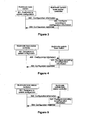
- Figure 2 shows a flowchart for NE configuration in a multimode system according to the first embodiment of the invention. The flow includes the following steps:
- Step 201 A multimode NE (multimode NE 1) updates configuration information of different modes dynamically when it determines that configuration update is needed, according to its detection or its interaction with other NEs in the multimode system. For example, its load condition, or resource utilization of its NE sub-nodes, or load conditions of its NE sub-nodes, or a combination of any of these, or after multimode NE 1 receives a configuration update request from another multimode system NE or some NEs in the multimode system.
- Step 202 Multimode NE 1 sends configuration information to a multimode system NE (multimode system NE 2). If multimode NE 1 and multimode system NE 2 are connected via a uniform interface, multimode NE 1 sends the configuration information to multimode system NE 2 via one piece of message; if multimode NE 1 and multimode system NE 2 are connected via distributed independent interfaces, multimode NE 1 may send the configuration information to multimode system NE 2 via several pieces of message.
- a multimode NE and a multimode system NE are connected via a uniform interface, they can exchange information via one or several pieces of message. In this embodiment of the invention, the interaction is done via one piece of message.
- Steps 203-204 In response to the received configuration information, multimode system NE 2 updates its configuration, for example, adjusting resource distribution dynamically or updating the related configuration, and sends a configuration response to multimode NE 1, notifying that the configuration is completed. If multimode NE 1 and multimode system NE 2 are connected via a uniform interface, multimode system NE 2 sends the configuration response to multimode NE 1 via one piece of message; if multimode NE 1 and multimode system NE 2 are connected via distributed independent interfaces, multimode system NE 2 may send the configuration response to multimode NE 1 via several pieces of message.
- multimode NE 1 may also store a configuration policy.
- a configuration policy When multimode NE 1 determines that configuration update is needed according to the configuration policy it stores, it updates the configuration information dynamically according to the configuration policy.
- a multimode communication system supports GSM and universal mobile telecommunications system (UMTS). Analysis on user activities shows that more GSM users are active in the period from 7:00 a.m. to 8:00 p.m., and that more UMTS users are active in the period from 8:00 p.m. to the next 7:00 a.m. Therefore, the configuration policy stored in multimode NE 1 may be set to allocate most system resources to GSM at 7:00 a.m. and allocate most system resources to UMTS at 8:00 p.m.
- GSM Global System for Mobile communications
- UMTS universal mobile telecommunications system
- multimode NE 1 will allocate most system resources to GSM and the rest of resources to UMTS at 7:00 a.m. and allocate most system resources to UMTS and the rest of resources to GSM at 8:00 p.m.
- multimode NE 1 may send configuration information to multimode system NE 2.
- Multimode system NE 2 then updates its configuration according to the received configuration information.
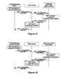
- FIG. 3 shows a flowchart for configuring a specific NE in a multimode system according to the first embodiment of the invention.
- multimode NE 1 is a multimode base station, which includes at least a BTS sub-node and a NodeB sub-node. All single-mode base stations in one multimode base station may be regarded as nodes in the multimode base station and herein referred to as sub-nodes of the multimode base station.
- Multimode system NE 2 is a multimode system base station controller, which may be a multimode base station controller or a single-mode controller. The flow includes the following steps:
- Step 301 The multimode base station detects that users accessed by the BTS sub-node are far fewer than those accessed by the NodeB sub-node in a specific period so that resources, such as carrier, power and air interface transmission resources, allocated to the BTS sub-node are relatively idle while resources allocated to the NodeB sub-node are relatively stringent. The multimode base station therefore determines that it is necessary to dynamically adjust the resources allocated to the BTS sub-node and the NodeB sub-node.
- resources such as carrier, power and air interface transmission resources
- the multimode base station adjusts the resources allocated to the BTS sub-node and the NodeB sub-node dynamically, for example, reducing the carrier or transmission resources allocated to the BTS sub-node and allocating this part of resources to the NodeB sub-node.
- Step 302 The multimode base station sends related configuration information to a multimode system base station controller.
- the configuration information may be the distribution of carrier or transmission resources. If the multimode base station and the multimode system base station controller are connected via a uniform interface, the multimode base station sends the configuration information to the multimode system base station controller via one piece of message; if they are connected via distributed independent interfaces, the multimode base station sends the configuration information to the multimode system base station controller via several pieces of message.
- the BTS sub-node sends a message via the interface with the multimode system BSC to provide configuration information for the multimode system BSC
- the NodeB sub-node sends a message via the interface with the multimode system RNC to provide configuration information for the multimode system RNC.
- the multimode system BSC may be a base station controller that supports only GSM in the multimode communication system, or a BSC sub-node in a multimode base station controller.
- the multimode system RNC may be a base station controller that supports only WCDMA in the multimode communication system, or an RNC sub-node in a multimode base station controller.
- Steps 303-304 Based on the received configuration information, the multimode system base station controller updates its configuration, for example, adjusting network resources dynamically, and sends a configuration response to the multimode base station, notifying the multimode base station that the configuration is completed. If the multimode base station and the multimode system base station controller are connected via a uniform interface, the multimode system base station controller sends the configuration response to the multimode base station via one piece of message; if they are connected via distributed independent interfaces, the multimode system base station controller sends the configuration response to the multimode base station via several pieces of message. For example, the multimode system BSC sends a configuration response via the interface with the BTS sub-node, and the multimode system RNC sends a configuration response via the interface with the NodeB sub-node.
- the multimode system BSC sends a configuration response via the interface with the BTS sub-node
- the multimode system RNC sends a configuration response via the interface with the NodeB sub-node.
- FIG. 4 shows another flowchart for configuring a specific NE in a multimode system according to the first embodiment of the invention.
- multimode NE 1 is a multimode base station controller, which includes at least a BSC sub-node and an RNC sub-node. All single-mode base station controllers in one multimode base station controller may be regarded as nodes in the multimode base station controller and herein referred to as sub-nodes of the multimode base station controller.
- Multimode system NE 2 is a multimode system base station, which may be a multimode base station or a single-mode base station. The flow includes the following steps:
- Step 401 The multimode base station controller detects that users accessed by the multimode system BTS are far fewer than those accessed by the multimode system NodeB in a specific period so that resources, such as carrier, power and air interface transmission resources, allocated to the BTS are relatively idle while resources allocated to the NodeB are relatively stringent.
- the multimode base station controller therefore determines that it is necessary to dynamically adjust the resources allocated to the multimode system BTS and NodeB. Then, the multimode base station controller adjusts the resources allocated to the multimode system BTS and NodeB dynamically, for example, reducing the carrier or transmission resources allocated to the multimode system BTS and allocating this part of resources to the multimode system NodeB.
- Step 402 The multimode base station controller sends configuration information to the multimode system base station, that is, the multimode system BTS and the multimode system NodeB.
- the configuration information may the distribution of carrier or transmission resources. If the multimode base station controller and the multimode system base station are connected via a uniform interface, the multimode base station controller sends the configuration information to the multimode system base station via one piece of message; if they are connected via distributed independent interfaces, the multimode base station controller sends the configuration information to the multimode system base station via several pieces of message.
- the BSC sub-node sends a message via the interface with the multimode system BTS to provide configuration information for the multimode system BTS
- the RNC sub-node sends a message via the interface with the multimode system NodeB to provide configuration information for the multimode system NodeB.
- the multimode system BTS may be a base station that supports only GSM in the multimode communication system, or a BTS sub-node in a multimode base station.
- the multimode system NodeB may be a base station that supports only WCDMA in the multimode communication system, or a NodeB sub-node in a multimode base station.
- Steps 403-304 Based on the received configuration information, the multimode system base station updates its configuration, for example, adjusting network resources dynamically, and sends a configuration response to the multimode base station controller, notifying the multimode base station controller that the configuration is completed. If the multimode base station controller and the multimode system base station are connected via a uniform interface, the multimode system base station sends the configuration response to the multimode base station controller via one piece of message; if they are connected via distributed independent interfaces, the multimode system base station sends the configuration response to the multimode base station controller via several piece of message. For example, the multimode system BTS sends a configuration response via the interface with the BSC sub-node, and the multimode system NodeB sends a configuration response via the interface with the RNC sub-node.
- the multimode system BTS sends a configuration response via the interface with the BSC sub-node
- the multimode system NodeB sends a configuration response via the interface with the RNC sub-node.
- FIG. 5 shows a third flowchart for configuring a specific NE in a multimode system according to the first embodiment of the invention.
- multimode NE 1 is a multimode base station controller, which includes at least a BSC sub-node and an RNC sub-node.
- Multimode system NE 2 is a multimode system base station controller. The flow includes the following steps:
- Step 501 The multimode base station controller detects that users accessed by the multimode system BTS are far fewer than those accessed by the multimode system NodeB in a specific period so that resources, such as carrier, power and air interface transmission resources, allocated to the BTS are relatively idle while resources allocated to the NodeB are relatively stringent.
- the multimode base station controller therefore determines that it is necessary to dynamically adjust the resources allocated to the multimode system BTS and NodeB. Then, the multimode base station controller adjusts the resources allocated to the multimode system BTS and NodeB dynamically, for example, reducing the carrier or transmission resources allocated to the multimode system BTS and allocating this part of resources to the multimode system NodeB.
- Step 502 The multimode base station controller sends related configuration information to an adjacent multimode system base station controller.
- the configuration information may the distribution of carrier or transmission resources. If the multimode base station controller and the multimode system base station controller are connected via a uniform interface, the multimode base station controller sends the configuration information to the multimode system base station controller via one piece of message; if they are connected via distributed independent interfaces, the multimode base station controller sends the configuration information to the multimode system base station controller via several pieces of message.
- the BSC sub-node sends a message via the interface with the multimode system BSC to provide configuration information for the multimode system BSC
- the RNC sub-node sends a message via the interface with the multimode system RNC to provide configuration information for the multimode system RNC.
- Steps 503-304 Based on the received configuration information, the multimode system base station controller updates its configuration, for example, adjusting network resources dynamically, and sends a configuration response to the multimode base station controller, notifying the multimode base station controller that the configuration is completed. If the multimode base station controller and the multimode system base station controller are connected via a uniform interface, the multimode system base station controller sends the configuration response to the multimode base station controller via one message; if they are connected via distributed independent interfaces, the multimode system base station controller sends the configuration response to the multimode base station controller via several messages. For example, the multimode system BSC sends a configuration response via the interface with the BSC sub-node, and the multimode system RNC sends a configuration response via the interface with the RNC sub-node.
- the multimode system BSC sends a configuration response via the interface with the BSC sub-node
- the multimode system RNC sends a configuration response via the interface with the RNC sub-node.
- Figure 6 shows a flowchart for NE configuration in a multimode system according to a second embodiment of the invention. The flow includes the following steps:
- Step 601 A multimode system NE (multimode system NE 1) collects information according to a preset rule, which defines the scope of information to collect, for example, the multimode system NE collects information of load condition and resource utilization.
- multimode system NE 1 there may be several multimode system NEs that collect information according to the preset rule, for instance, multimode system NE 1 and several other multimode system NEs may collect information simultaneously according to the preset rule.
- the multimode system NE may send a configuration update request to several adjacent multimode system NEs, requesting the adjacent multimode system NEs to update the configuration information.
- the multimode system NE may determine to which multimode system NEs it will send the configuration update request based on one of the following rules or any of their combinations:
- Multimode system NE 1 reports the collected information to a multimode NE (multimode NE 2).
- Multimode system NE 1 may report the collected information at preset reporting intervals to an O&M module; or it may report the collected information to multimode NE 2 when a preset trigger is activated. For example, when the collected load falls below a preset value, multimode system NE 1 reports the collected information to multimode NE 2; or regular reporting and triggered reporting may be combined, which means, when the current time reaches the defined interval border or when the preset trigger is activated, multimode system NE 1 reports the collected information to multimode NE 2.
- multimode system NE 1 reports the collected information to multimode NE 2 via one piece of message; if multimode system NE 1 and multimode NE 2 are connected via distributed independent interfaces, multimode system NE 1 may report the collected information to multimode NE 2 via several piece of message.
- Step 603 Based on the received collected information and the preset configuration policy, when multimode NE 2 determines that configuration update is needed it updates the configuration information of different modes dynamically according to the collected information.
- Multimode NE 2 sends configuration information to multimode system NE 1.
- multimode system NE 1 updates its configuration and sends a configuration response to multimode NE 2, notifying that the configuration is completed. If multimode system NE 1 and multimode NE 2 are connected via a uniform interface, multimode system NE 1 sends the configuration response to multimode NE 2 via one piece of message; if multimode system NE 1 and multimode NE 2 are connected via distributed independent interfaces, multimode system NE 1 may send the configuration response to multimode NE 2 via several pieces of message.
- Multimode system NE 1 may report the collected information to multimode NE 2 directly or via an O&M module.
- FIG. 7 shows a flowchart for configuring a specific NE in a multimode system according to the second embodiment of the invention.
- multimode system NE 1 is a multimode system base station
- multimode NE 2 is a multimode base station. The flow includes the following steps:
- Step 701 The multimode system base station collects information according to a preset rule, for instance, for a multimode base station that includes a BTS sub-node and a NodeB sub-node, the multimode system base station collects the load information and the utilization of carrier, power and transmission resources in the BTS sub-node and the NodeB sub-node.
- a preset rule for instance, for a multimode base station that includes a BTS sub-node and a NodeB sub-node, the multimode system base station collects the load information and the utilization of carrier, power and transmission resources in the BTS sub-node and the NodeB sub-node.
- Step 702 The multimode system base station reports the collected information to the multimode base station.
- the multimode system base station may report the collected information to the multimode base station at preset reporting intervals; or it may report the collected information to the multimode base station when a preset trigger is activated; or regular reporting and triggered reporting may be combined, which means, when the current time reaches the defined interval border or when the preset trigger is activated, the multimode system base station reports the collected information to the multimode base station.
- Step 703 Based on the received the collected information, the multimode base station determines that configuration update is needed according to the collected information and the preset configuration policy and updates the configuration information of different modes dynamically according to the collected information.
- Steps 704-705 The multimode base station sends configuration information to the multimode system base station. Based on the received configuration information, the multimode system base station updates its configuration according to the configuration information and sends a configuration response to the multimode base station, notifying that the configuration is completed. If the multimode system base station and the multimode base station are connected via a uniform interface, the multimode system base station sends the configuration response to the multimode base station via one message; if they are connected via distributed independent interfaces, the multimode system base station may send the configuration response to the multimode base station via several messages.
- FIG. 8 shows another flowchart for configuring a specific NE in a multimode system according to the second embodiment of the invention.
- multimode system NE 1 is a multimode system base station
- multimode NE 2 is a multimode base station controller. The flow includes the following steps:
- Step 801 The multimode system base station collects information according to a preset rule.
- Step 802 The multimode system base station reports the collected information to the multimode base station controller.
- the multimode system base station may report the collected information to the multimode base station controller at preset reporting intervals; or it may report the collected information to the multimode base station controller when a preset trigger is activated; or regular reporting and triggered reporting may be combined, which means, when the current time reaches the defined interval border or when the preset trigger is activated, the multimode system base station reports the collected information to the multimode base station controller.
- Step 803 Based on the received collected information, the multimode base station controller determines that configuration update is needed according to the collected information and the preset configuration policy and updates the configuration information of different modes dynamically according to the collected information.
- Steps 804-805 The multimode base station controller sends configuration information to the multimode system base station. Based on the received configuration information, the multimode system base station updates its configuration according to the configuration information and sends a configuration response to the multimode base station controller, notifying that the configuration is completed. If the multimode system base station and the multimode base station controller are connected via a uniform interface, the multimode system base station sends the configuration response to the multimode base station controller via one message; if they are connected via distributed independent interfaces, the multimode system base station may send the configuration response to the multimode base station controller via several messages.
- FIG. 9 shows a third flowchart for configuring a specific NE in a multimode system according to the second embodiment of the invention.
- multimode system NE 1 is a multimode system base station controller
- multimode NE 2 is a multimode base station controller. The flow includes the following steps:
- Step 901 The multimode system base station controller collects information according to a preset rule.
- Step 902 The multimode system base station controller reports the collected information to the multimode base station controller.
- the multimode system base station controller may report the collected information to the multimode base station controller at preset reporting intervals; or it may report the collected information to the multimode base station controller when a preset trigger is activated; or regular reporting and triggered reporting may be combined, which means, when the current time reaches the defined interval border or when the preset trigger is activated, the multimode system base station controller reports the collected information to the multimode base station controller.
- Step 903 Based on the received collected information, the multimode base station controller determines that configuration update is needed according to the collected information and the preset configuration policy and updates the configuration information of different modes dynamically according to the collected information.
- Steps 904-905 The multimode base station controller sends configuration information to the multimode system base station controller. Based on the received configuration information, the multimode system base station controller updates its configuration according to the configuration information and sends a configuration response to the multimode base station controller, notifying that the configuration is completed. If the multimode system base station controller and the multimode base station controller are connected via a uniform interface, the multimode system base station controller sends the configuration response to the multimode base station controller via one message; if they are connected via distributed independent interfaces, the multimode system base station controller may send the configuration response to the multimode base station controller via several messages.
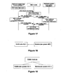
- FIG. 10 shows a flowchart for NE configuration in a multimode system according to the third embodiment of the invention.
- the multimode communication system includes an O&M module.
- the O&M module may be a physical entity in the system, or a logical entity implemented in some equipment, like an operation and management center (OMC) or a multimode system base station controller.
- O&M operation and management center
- the flow includes the following steps:
- Step A01 A multimode NE (multimode NE 1) determines that configuration update is needed, for example, according to its detection or its interaction with other NEs in the multimode system, and updates the configuration information of different modes dynamically.
- Step A02 Multimode NE 1 sends the configuration information to the O&M module, requesting the O&M module to notify other multimode system NEs to update their configuration information. If multimode NE 1 and the O&M module are connected via a uniform interface, multimode NE 1 sends the configuration information to the O&M module via one message; if multimode NE 1 and the O&M module are connected via distributed independent interfaces, multimode NE 1 may send the configuration information to the O&M module via several messages.
- Step A03 The O&M module sends configuration information to a multimode system NE (multimode system NE 2). If the O&M module and multimode system NE 2 are connected via a uniform interface, the O&M module sends the configuration information to multimode system NE 2 via one message; if the O&M module and multimode system NE 2 are connected via distributed independent interfaces, the O&M module may send the configuration information to multimode system NE 2 via several messages.
- the O&M module may send the configuration information to more than one multimode system NE by repeating step A03.
- Steps A04-A05 Based on the received configuration information, multimode system NE 2 updates its configuration according to the configuration information and sends a configuration response to the O&M module, notifying that the configuration is completed. If multimode system NE 2 and the O&M module are connected via a uniform interface, multimode system NE 2 sends the configuration response to the O&M module via one message; if multimode system NE 2 and the O&M module are connected via distributed independent interfaces, multimode system NE 2 may send the configuration response to the O&M module via several messages.
- Step A06 Based on the received configuration response, the O&M module stores the configuration result and may update the display on the management interface. If the O&M module sends the configuration information to more than one multimode system NE, the O&M module will repeat step A06. This step may be omitted.
- Step A07 The O&M module sends a configuration response to multimode NE 1, notifying that the configuration is completed. If multimode NE 1 and the O&M module are connected via a uniform interface, the O&M module sends the configuration response to multimode NE 1 via one message; if multimode NE 1 and the O&M module are connected via distributed independent interfaces, the O&M module may send the configuration response to multimode NE 1 via several messages.
- multimode NE 1 may also store a configuration policy.
- multimode NE 1 determines that configuration update is needed according to the configuration policy it stores, it updates the configuration information dynamically according to the configuration policy.
- it may send configuration information to the O&M module, requesting the O&M module to notify other multimode system NEs to update their configuration information.
- the O&M module sends the configuration information to other multimode system NEs.
- the other multimode system NEs update their configuration information according to the received configuration information.
- FIG 11 shows a flowchart for configuring a specific NE in a multimode system according to the third embodiment of the invention.
- multimode NE 1 is a multimode base station, which includes at least a BTS sub-node and a NodeB sub-node.
- Multimode system NE 2 is a multimode system base station controller. The flow includes the following steps:
- Step B01 The multimode base station detects that users accessed by the BTS sub-node are far fewer than those accessed by the NodeB sub-node in a specific period so that resources, such as carrier, power and air interface transmission resources, allocated to the BTS sub-node are idle while resources allocated to the NodeB sub-node are relatively stringent. The multimode base station therefore determines that it is necessary to dynamically adjust the resources allocated to the BTS sub-node and the NodeB sub-node.
- resources such as carrier, power and air interface transmission resources
- the multimode base station adjusts the resources allocated to the BTS sub-node and the NodeB sub-node dynamically, for example, reducing the carrier or transmission resources allocated to the BTS sub-node and allocating this part of resources to the NodeB sub-node.
- Steps B02-B03 The multimode base station sends configuration information to an O&M module, requesting the O&M module to notify the multimode system base station controller to update its configuration, and the O&M module sends the configuration information to the multimode system base station controller.
- Steps B03-B04 Based on the received configuration information, the multimode system base station controller updates its configuration according to the configuration information, for example, adjusting network resources dynamically, and sends a configuration response to the multimode base station, notifying the multimode base station that the configuration is completed.
- Step B06 configuration response, the O&M module stores the configuration result and may update the display on the management interface.
- Step B07 The O&M module sends a configuration response to the multimode base station, notifying that the configuration is completed.
- FIG. 12 shows another flowchart for configuring a specific NE in a multimode system according to the third embodiment of the invention.
- multimode NE 1 is a multimode base station controller, which includes at least BSC sub-node and an RNC sub-node.
- Multimode system NE 2 is a multimode system base station. The flow includes the following steps:
- Step C01 The multimode base station controller detects that users accessed by the multimode system BTS are far fewer than those accessed by the multimode system NodeB in a specific period so that resources, such as carrier, power and air interface transmission resources, allocated to the BTS are idle while resources allocated to the NodeB are relatively stringent.
- the multimode base station controller therefore determines that it is necessary to dynamically adjust the resources allocated to the multimode system BTS and NodeB. Then, the multimode base station controller adjusts the resources allocated to the multimode system BTS and NodeB dynamically, for example, reducing the carrier or transmission resources allocated to the multimode system BTS and allocating this part of resources to the multimode system NodeB.
- Steps C02-C03 The multimode base station controller sends configuration information to an O&M module, requesting the O&M module to notify the multimode system base station to update its configuration, and the O&M module sends the configuration information to the multimode system base station.
- Steps C03-C04 Based on the received configuration information, the multimode system base station updates its configuration according to the configuration information, for example, adjusting network resources dynamically, and sends a configuration response to the O&M module, notifying that the configuration is completed.
- Step C06 Based on the received configuration response, the O&M module stores the configuration result and may update the display on the management interface.
- Step C07 The O&M module sends a configuration response to the multimode base station controller, notifying that the configuration is completed.
- FIG. 13 shows a third flowchart for configuring a specific NE in a multimode system according to the third embodiment of the invention.
- multimode NE 1 is a multimode base station controller, which includes at least a BSC sub-node and an RNC sub-node.
- Multimode system NE 2 is a multimode system base station controller. The flow includes the following steps:
- Step D01 The multimode base station controller detects that users accessed by the multimode system BTS are far fewer than those accessed by the multimode system NodeB in a specific period so that resources, such as carrier, power and air interface transmission resources, allocated to the BTS are idle while resources allocated to the NodeB are relatively stringent.
- the multimode base station controller therefore determines that it is necessary to dynamically adjust the resources allocated to the multimode system BTS and NodeB. Then, the multimode base station controller adjusts the resources allocated to the multimode system BTS and NodeB dynamically, for example, reducing the carrier or transmission resources allocated to the multimode system BTS and allocating this part of resources to the multimode system NodeB.
- Steps D02-D03 The multimode base station controller sends configuration information to an O&M module, requesting the O&M module to notify the adjacent multimode system base station controller to update its configuration, and the O&M module sends the configuration information to the multimode system base station controller.
- Steps D03-D04 Based on the received configuration information, the multimode system base station controller updates its configuration according to the configuration information, for example, adjusting network resources dynamically, and sends a configuration response to the O&M module, notifying that the configuration is completed.
- Step D06 Based on the received configuration response, the O&M module stores the configuration result and may update the display on the management interface.
- Step D07 The O&M module sends a configuration response to the multimode base station controller, notifying that the configuration is completed.
- FIG 14 shows a flowchart for NE configuration in a multimode system according to the fourth embodiment of the invention.
- the multimode communication system includes an O&M module.
- the O&M module may be a physical entity in the system, or a logical entity implemented in some equipment, like an OMC or a multimode system base station controller.
- the flow includes the following steps:
- Step E01 A multimode system NE (multimode system NE 1) collects information according to a preset rule, which defines the scope of information to collect, for example, the multimode system NE collects information of load condition and resource utilization.
- multimode system NE 1 there may be several multimode system NEs that collect information according to the preset rule, for instance, multimode system NE 1 and another multimode system NE (multimode system NE 2) may collect information simultaneously according to the preset rule.
- multimode system NE 2 may collect information simultaneously according to the preset rule.
- Multimode system NE 1 reports the collected information to the O&M module.
- Multimode system NE 1 may report the collected information at preset reporting intervals to the O&M module; or it may report the collected information to the O&M module when a preset trigger is activated, for example, when the collected load falls below a preset value, multimode system NE 1 reports the collected information to the O&M module; or regular reporting and triggered reporting may be combined, which means, when the current time reaches the defined interval border or when the preset trigger is activated, multimode system NE 1 reports the collected information to the O&M module.
- multimode system NE 1 reports the collected information to the O&M module via one message; if multimode system NE 1 and the O&M module are connected via distributed independent interfaces, multimode NE 1 may report the collected information to the O&M module via several messages.
- Step E03 Based on the received collected information, the O&M module determines that configuration update is needed according to the collected information and the preset configuration policy, determines configuration information according to the collected information, and then goes on to execute only steps E04-E06, or only steps E07-E09, or both steps E04-E06 and steps E07-E09.
- Steps E04-E06 The O&M module sends the configuration information to multimode system NE 1 and, based on the received information, multimode system NE 1 updates its configuration according to the information and sends a configuration response to the O&M module, notifying that the configuration is completed.
- Steps E07-E09 The O&M module sends the configuration information to multimode system NE 2 and, based on the received information, multimode system NE 2 updates its configuration according to the information and sends a configuration response to the O&M module, notifying that the configuration is completed.
- steps E04-E06 and steps E07-E09. may be executed simultaneously; or steps E04-E06 are executed before steps E07-E09; or steps E07-E09 are executed before steps E04-E06.
- Step E10 Based on the received configuration response, the O&M module stores the configuration result and may update the display on the management interface. If the O&M module sends the configuration information to more than one multimode system NE, the O&M module will repeat step E10. This step may be omitted.
- FIG. 15 shows a flowchart for configuring a specific NE in a multimode system according to the fourth embodiment of the invention.
- multimode system NE 1 is a multimode system base station
- multimode system NE 2 is a multimode system base station controller. The flow includes the following steps:
- Step F01 The multimode system base station collects information according to a preset rule, for instance, for a multimode base station that includes a BTS sub-node and a NodeB sub-node, the multimode system base station collects the load information and the utilization of carrier, power and transmission resources in the BTS sub-node and the NodeB sub-node.
- a preset rule for instance, for a multimode base station that includes a BTS sub-node and a NodeB sub-node, the multimode system base station collects the load information and the utilization of carrier, power and transmission resources in the BTS sub-node and the NodeB sub-node.
- Step F02 The multimode system base station reports the collected information to an O&M module.
- the multimode system base station may report the collected information to the O&M module at preset reporting intervals; or it may report the collected information to the O&M module when a preset trigger is activated; or regular reporting and triggered reporting may be combined, which means, when the current time reaches the defined interval border or when the preset trigger is activated, the multimode system base station reports the collected information to the O&M module.
- Step F03 Based on the received collected information, the O&M module determines that configuration update is needed according to the collected information and the preset configuration policy, determines configuration information according to the collected information, and executes steps F04-F06 and steps F07-F09.
- Steps F04-F06 The O&M module sends the configuration information to the multimode system base station and, based on the received information, the multimode system base station updates its configuration according to the information and sends a configuration response to the O&M module, notifying that the configuration is completed.
- Steps F07-F09 The O&M module sends the configuration information to the multimode system base station controller and, based on the received information, the multimode system base station controller updates its configuration according to the information and sends a configuration response to the O&M module, notifying that the configuration is completed.
- Step F10 Based on the received configuration response, the O&M module stores the configuration result and may update the display on the management interface.
- FIG. 16 shows a flowchart for configuring a specific NE in a multimode system according to the fourth embodiment of the invention.
- multimode system NE 1 is a multimode system base station controller and multimode system NE 2 is a multimode system base station. The flow includes the following steps:
- Step G01 The multimode system base station controller collects information according to a preset rule, for instance, for a multimode base station controller that includes a BSC sub-node and an RNC sub-node, the multimode system base station controller collects the load information of the BSC sub-node and the RNC sub-node.
- a preset rule for instance, for a multimode base station controller that includes a BSC sub-node and an RNC sub-node, the multimode system base station controller collects the load information of the BSC sub-node and the RNC sub-node.
- Step G02 The multimode system base station controller reports the collected information to an O&M module.
- the multimode system base station controller may report the collected information to the O&M module at preset reporting intervals; or it may report the collected information to the O&M module when a preset trigger is activated; or regular reporting and triggered reporting may be combined, which means, when the current time reaches the defined interval border or when the preset trigger is activated, the multimode system base station controller reports the collected information to the O&M module.
- Step G03 Based on the received collected information, the O&M module determines that configuration update is needed according to the collected information and the preset configuration policy, determines configuration information according to the collected information, and executes steps G04-G06 and steps G07-G09.
- Steps G04-G06 The O&M module sends the configuration information to the multimode system base station controller and, based on the received information, the multimode system base station controller updates its configuration according to the information and sends a configuration response to the O&M module, notifying that the configuration is completed.
- Steps G07-G09 The O&M module sends the configuration information to the multimode system base station and, based on the received information, the multimode system base station updates its configuration according to the information and sends a configuration response to the O&M module, notifying that the configuration is completed.
- Step G10 Based on the received configuration response, the O&M module stores the configuration result and may update the display on the management interface.
- FIG 17 shows a flowchart for configuring a specific NE in a multimode system according to the fourth embodiment of the invention.
- both multimode system NE 1 and multimode system NE 2 are multimode system base station controllers. The flow includes the following steps:
- Step H01 A multimode system base station controller (multimode system base station controller 1) collects information according to a preset rule.
- Step H02 Multimode system base station controller 1 reports the collected information to an O&M module.
- Multimode system base station controller 1 may report the collected information to the O&M module at preset reporting intervals; or it may report the collected information to the O&M module when a preset trigger is activated; or regular reporting and triggered reporting may be combined, which means, when the current time reaches the defined interval border or when the preset trigger is activated, multimode system base station controller 1 reports the collected information to the O&M module.
- Step H03 Based on the received collected information, the O&M module determines that configuration update is needed according to the collected information and the preset configuration policy, determines configuration information according to the collected information, and executes steps H04-H06 and steps H07-H09.
- Steps H04-H06 The O&M module sends the configuration information to multimode system base station controller 1 and, based on the received information, multimode system base station controller 1 updates its configuration according to the information and sends a configuration response to the O&M module, notifying that the configuration is completed.
- Steps H07-H09 The O&M module sends the configuration information to another multimode system base station controller (multimode system base station controller 2) and, based on the received information, multimode system base station controller 2 updates its configuration according to the information and sends a configuration response to the O&M module, notifying that the configuration is completed.
- multimode system base station controller 2 multimode system base station controller 2 updates its configuration according to the information and sends a configuration response to the O&M module, notifying that the configuration is completed.
- Step H10 Based on the received configuration response, the O&M module stores the configuration result and may update the display on the management interface.
- the O&M module may store a configuration policy.
- the O&M module determines that configuration update is needed according to the configuration policy it stores, it sends configuration information to multimode system NEs according to the configuration policy, notifying them to update their configuration information.
- the multimode communication system supports GSM and WiMAX. Analysis on user activities shows that more GSM users are active in the period between 8:00 a.m. and 8:00 p.m. and that more WiMAX users are active in the period between 8:00 p.m. and 8:00 a.m. Therefore, the configuration policy stored in the O&M module may be set to allocate most system resources to GSM at 8:00 a.m. and allocate most system resources to WiMAX at 8:00 p.m.
- the O&M module notifies the multimode system base station controller to allocate most system resources to GSM and the rest of resources to WiMAX at 8:00 a.m. and notifies the multimode system base station controller to allocate most system resources to WiMAX and the rest of resources to GSM at 8:00 p.m.
- the multimode system base station controller may send configuration information to a multimode system base station.
- the multimode system base station then updates its configuration according to the received information.
- Figure 18 shows the structure of a system for implementing NE configuration in a multimode system according to the fourth embodiment of the invention.
- the system includes at least two multimode system NEs.
- Multimode NE 1 updates the configuration information of different modes dynamically and sends the configuration information to multimode system NE 2 when it determines that configuration update is necessary.
- Multimode system NE 2 updates single-mode configuration according to the received configuration information. Further, multimode system NE 2 notifies multimode NE 1 of the completion of configuration.
- a multimode system NE in the multimode communication system may collect information according to a preset rule and report the collected information to a multimode NE.
- the multimode NE receiving the collected information determines whether configuration update is needed according to the collected information and a preset configuration policy and if so, updates the configuration information of different modes and sends the configuration to the multimode system NE that reports the collected information.
- the multimode system NE updates single-mode configuration according to the received configuration information.
- Figure 19 shows the structure of a system for implementing NE configuration in a multimode system according to the fifth embodiment of the invention.
- the system includes at least two multimode system NEs and an O&M module.
- One multimode system NE (multimode system NE 1) updates configuration information dynamically and sends the configuration information to the O&M module when it determines that configuration update is needed.
- the O&M sends the configuration information to another multimode system NE (multimode system NE 2).
- Multimode system NE 2 updates its configuration according to the received configuration information.
- the O&M module may store the configuration result and further update the display on its management interface. Further, multimode system NE 2 notifies multimode system NE 1 of the completion of configuration via the O&M module.
- the O&M module may further determine whether configuration update is needed according to the configuration policy it stores, and send configuration information to multimode system NEs according to the configuration policy, notifying them to update their configuration information.
- a multimode system NE in the multimode communication system may collect information according to a preset rule.
- Multimode system NE 1 and/or multimode system NE 2, and/or other multimode system NEs collect information according to the preset rule, report the collected information to the O&M module and update their configuration according to received configuration information; the O&M module determines whether configuration update is needed according to the collected information and the preset configuration policy and if so, determines configuration information and sends the configuration information to multimode system NE 1 and/or multimode system NE 2, and/or other multimode system NEs.
- multimode system NEs that complete the configuration may notify the O&M module of the completion of the configuration.
- the O&M module may store the configuration result and further update the display on its management interface.
Landscapes
- Engineering & Computer Science (AREA)
- Computer Networks & Wireless Communication (AREA)
- Signal Processing (AREA)
- Mobile Radio Communication Systems (AREA)
Description
- The present invention relates to the radio communication industry and particularly to a method and system for network element (NE) configuration in a multimode communication system.
- With the development of radio communications, more and more radio access technologies (RATs) are brought into use. A variety of RATs includes global system for mobile communications (GSM), wideband code division multiple access (WCDMA), world interoperability for microwave access (WiMAX), long term evolution (LTE), air interface evolution (AIE) and code division multiple access (CDMA) 2000. These RATs correspond to a variety of base station systems. For example, base station is named as base transceiver station (BTS) in GSM, named as NodeB in WCDMA named as base station in WiMAX and eNodeB in LTE. In the current mobile communication systems, each base station operates as an individual equipment node. In future mobile communication networks, these base stations are likely to coexist within one node and share part of the node resources, such as the backplane bus, CPU, memory of the node and even some boards of the node.
- Herein "within one node" includes the physical expansion of the equipment node, for instance, capacity expansion by cascade of shelves. A base station which supports multiple RATs is named a multimode base station hereafter.
- A multimode base station can be deployed as in
Figure 1A . In addition, because a multimode base station can share some physical resources, different RAT-enabled base stations within a multimode base station may possess features different from a single-mode base station. For example, a GSM base station in a multimode base station may possess some functions of a GSM base station controller (BSC). This means the GSM base station is an enhanced BTS+BSC station. A NodeB in a multimode base station may also be an enhanced WCDMA station, for instance, it may possess the functions of a radio network controller (RNC). An enhanced multimode base station is shown inFigure 1B . -
WO 2005/039210 A1 describes a system and method for achieving interoperability between telecommunication servers such as Mobile Switching Centers (MSCs) in a mobile communication network by automatically distributing capability and configuration information between the MSCs. According to the method, whenever one of the MSCs is started-up, or undergoes any other procedure that changes the configuration or capabilities of the MSC, the started-up MSC automatically sends its capabilities and configuration information to its neighboring MSCs. -
US 2003/208579 A1 describes a method and a system for updating software configuration of line-replaceable unit (LRU) computers in a restricted architecture network such as an in-flight entertainment system. -
WO02/30141 A1 - The launch of multimode base stations brings the concept of a multimode communication system, which is a system that supports multiple modes. This raises new requirements on the operation and maintenance (O&M) of NEs in a multimode communication system. Because all the current O&M actions are based on single-mode NEs, the requirement on O&M for NEs in a multimode communication system may not be satisfied.
- In view of this, the present invention discloses a method and system for NE configuration in a multimode communication system.
- According to an embodiment of the invention, a method for NE configuration in a multimode communication system, the multimode communication system is a system that supports multiple modes, the mode is at least one of global system for mobile, GSM, wideband code division multiple access,WCDMA, world interoperability for microwave access, WiMAX, long term evolution, LTE, air interface evolution, AIE, and code division multiple access, CDMA. which includes: determining, by a first multimode NE, a configuration update is needed according to any one of: 1)a detection by the first multimode NE, 2)an interaction of the first multimode NE with an NE in the multimode communication system, and 3)a configuration policy stored in the first multimode NE,; by the first multimode NE, updating configuration information of different modes of the first multimode NE dynamically to obtain a update configuration information and sending the updated configuration information to a second multimode system NE,; updating, by the second multimode system NE, its configuration according to the received configuration information, wherein the first multimode NE and second multimode system NE support at least two different modes in a radio access network.
- According to an embodiment of the invention, a method for NE configuration in a multimode communication system, the multimode communication system is a system that supports multiple modes, the mode is at least one of global system for mobile, GSM, wideband code division multiple access,WCDMA, world interoperability for microwave access, WiMAX, long term evolution, LTE, air interface evolution, AIE, and code division multiple access, CDMA, which includes: by a multimode system NE, collecting information according to a preset rule and reporting the collected information to another multimode NE in the multimode communication system determining, by the multimode NE receiving the collected information, that configuration update is needed according to the collected information and a preset configuration policy; updating, by the multimode NE, configuration information of different modes dynamically according to the received information, wherein the multimode NE and multimode system NE support at least two different modes in a radio access network.
- According to an embodiment of the invention, a method for NE configuration in a multimode communication system, the multimode communication system is a system that supports multiple modes, the mode is at least one of global system for mobile, GSM, wideband code division multiple access,WCDMA, world interoperability for microwave access, WiMAX, long term evolution, LTE, air interface evolution, AIE, and code division multiple access, CDMA, which includes: by a multimode system NE, collecting information according to a preset rule and reporting the collected information to an O&M module; sending, by the O&M module, configuration information to the multimode system NE according to the received information; updating, by the multimode system NE, the configuration according to the received configuration information. The multimode system NE that receives the configuration information is the multimode system NE that collects information, or a combination of the multimode system NE collecting information and a multimode system NE other than the one colleting information, wherein the multimode system NEs support at least two different modes in a radio access network.
- According to an embodiment of the invention, a system for NE configuration in a multimode communication system , the multimode communication system is a system that supports multiple modes, the mode is at least one of global system for mobile, GSM, wideband code division multiple access, WCDMA, world interoperability for microwave access, WiMAX, long term evolution, LTE, air interface evolution, AIE, and code division multiple access, CDMA, which includes at least a first multimode NE and a second multimode system NE. The first multimode NE updates configuration information of different modes dynamically and sends configuration information to the second multimode system NE; the second multimode system NE updates its configuration according to the received configuration information, wherein the first multimode NE and second multimode system NE support at least two different modes in a radio access network.
- According to an embodiment of the invention, a system for NE configuration in a multimode communication system includes at least a first multimode system NE and a second multimode NE. The multimode communication system is a system that supports multiple modes, the mode is at least one of global system for mobile, GSM, wideband code division multiple access, WCDMA, world interoperability for microwave access, WiMAX, long term evolution, LTE, air interface evolution, AIE, and code division multiple access, CDMA. The first multimode system NE collects information according to a preset rule and reports the collected information to the second multimode NE; the second multimode NE updates configuration information of different modes dynamically according to the collected information, wherein the first multimode NE and second multimode system NE support at least two different modes in a radio access network.
- According to an embodiment of the invention, a system for NE configuration in a multimode communication system, the multimode communication system is a system that supports multiple modes, the mode is at least one of global system for mobile, GSM, wideband code division multiple access, WCDMA, world interoperability for microwave access, WiMAX, long term evolution, LTE, air interface evolution, AlE, and code division multiple access, CDMA, which includes at least an O&M module and one or more multimode system NEs. The multimode system NE collects information according to a preset rule and reports the collected information to the O&M module; the O&M module sends configuration information to the multimode system NE according to the received collected information; the multimode system NE updates its configuration according to the received configuration information; the multimode system NE receiving the configuration information is the multimode system NE that collects information, or a multimode system NE other than the one collecting information, or a combination of the two, wherein the multimode system NEs support at least two different modes in a radio access network.
- In the embodiments of the invention, after a multimode system NE changes configuration information, it sends a configuration update request to other multimode system NEs. The NE may send configuration information to the other multimode system NEs directly or via an O&M module. This enables a multimode communication system to carry out more rational configuration in the whole system based on the load condition, resource utilization and other configuration information of all single-mode NEs. For instance, the system can allocate idle resources dynamically to multimode system NEs that are short of resources, so that the configurations of all modes supported are considered comprehensively. This helps realize the dynamic configuration and dynamic adjustment of resources, improve the resource utilization of the multimode communication system and reduce the operation cost of the system.
- In addition, the NEs in the multimode communication system may report the collected information to an O&M module. When the O&M module determines that configuration is necessary according to the collected information, the O&M module sends configuration information to the multimode system NE and other NEs in the system, so that the NEs can perform configurations according to the configuration information, thus realizing the dynamic configuration and dynamic adjustment of resources.
-
-
Figure 1A shows a multimode base station; -
Figure 1B shows another multimode base station; -
Figure 2 shows a flowchart for NE configuration in a multimode system according to a first embodiment of the invention; -
Figure 3 shows a flowchart for configuring a specific NE in a multimode system according to the first embodiment of the invention; -
Figure 4 shows another flowchart for configuring a specific NE in a multimode system according to the first embodiment of the invention; -
Figure 5 shows a third flowchart for configuring a specific NE in a multimode system according to the first embodiment of the invention; -
Figure 6 shows a flowchart for NE configuration in a multimode system according to a second embodiment of the invention; -
Figure 7 shows a flowchart for configuring a specific NE in a multimode system according to the second embodiment of the invention; -
Figure 8 shows another flowchart for configuring a specific NE in a multimode system according to the second embodiment of the invention; -
Figure 9 shows a third flowchart for configuring a specific NE in a multimode system according to the second embodiment of the invention; -
Figure 10 shows a flowchart for NE configuration in a multimode system according to a third embodiment of the invention; -
Figure 11 shows a flowchart for configuring a specific NE in a multimode system according to the third embodiment of the invention; -
Figure 12 shows another flowchart for configuring a specific NE in a multimode system according to the third embodiment of the invention; -
Figure 13 shows a third flowchart for configuring a specific NE in a multimode system according to the third embodiment of the invention; -
Figure 14 shows a flowchart for NE configuration in a multimode system according to a fourth embodiment of the invention; -
Figure 15 shows a flowchart for configuring a specific NE in a multimode system according to the fourth embodiment of the invention; -
Figure 16 shows another flowchart for configuring a specific NE in a multimode system according to the fourth embodiment of the invention; -
Figure 17 shows a third flowchart for configuring a specific NE in a multimode system according to the fourth embodiment of the invention; -
Figure 18 shows the structure of a system for implementing NE configuration in a multimode system according to the fourth embodiment of the invention; and -
Figure 19 shows the structure of a system for implementing NE configuration in a multimode system according to a fifth embodiment of the invention. - A multimode communication system needs to consider in a comprehensive way the configuration of all modes it supports so as to allocate radio resources rationally to base stations of all modes. In the embodiments of the invention, after an NE in a multimode system changes configuration information, it sends a configuration update request to other NEs in the multimode system. The NE may send configuration information to other NEs directly or via an O&M module. For example, an NE in the multimode system may report information it collects to the O&M module. When the O&M determines that configuration is necessary according to the collected information, the O&M module sends configuration information to this NE and other NEs in the system, so that the NEs in the multimode communication system can perform configurations according to the configuration information. For the purpose of description, herein, an NE in a multimode communication system is referred to as a multimode system NE. A multimode system NE may be an NE that supports multiple modes, and in this sense, it is a multimode NE, for instance, a multimode base station, a multimode base station controller, or a multimode core network (CN) node. A multimode system NE may also be one or multiple NEs that support a single mode, for instance, a BTS, a BSC, a serving GPRS support node (SGSN) or a gateway (GW). A single-mode logical module in a multimode NE may be regarded as a node in the NE. Herein, such a single-mode logical module is referred to as an NE sub-node.
-
Figure 2 shows a flowchart for NE configuration in a multimode system according to the first embodiment of the invention. The flow includes the following steps: - Step 201: A multimode NE (multimode NE 1) updates configuration information of different modes dynamically when it determines that configuration update is needed, according to its detection or its interaction with other NEs in the multimode system. For example, its load condition, or resource utilization of its NE sub-nodes, or load conditions of its NE sub-nodes, or a combination of any of these, or after
multimode NE 1 receives a configuration update request from another multimode system NE or some NEs in the multimode system. - Step 202:
Multimode NE 1 sends configuration information to a multimode system NE (multimode system NE 2). Ifmultimode NE 1 andmultimode system NE 2 are connected via a uniform interface,multimode NE 1 sends the configuration information tomultimode system NE 2 via one piece of message; ifmultimode NE 1 andmultimode system NE 2 are connected via distributed independent interfaces,multimode NE 1 may send the configuration information tomultimode system NE 2 via several pieces of message. When a multimode NE and a multimode system NE are connected via a uniform interface, they can exchange information via one or several pieces of message. In this embodiment of the invention, the interaction is done via one piece of message. - Steps 203-204: In response to the received configuration information,
multimode system NE 2 updates its configuration, for example, adjusting resource distribution dynamically or updating the related configuration, and sends a configuration response tomultimode NE 1, notifying that the configuration is completed. Ifmultimode NE 1 andmultimode system NE 2 are connected via a uniform interface,multimode system NE 2 sends the configuration response tomultimode NE 1 via one piece of message; ifmultimode NE 1 andmultimode system NE 2 are connected via distributed independent interfaces,multimode system NE 2 may send the configuration response tomultimode NE 1 via several pieces of message. - In addition,
multimode NE 1 may also store a configuration policy. When multimodeNE 1 determines that configuration update is needed according to the configuration policy it stores, it updates the configuration information dynamically according to the configuration policy. For example, a multimode communication system supports GSM and universal mobile telecommunications system (UMTS). Analysis on user activities shows that more GSM users are active in the period from 7:00 a.m. to 8:00 p.m., and that more UMTS users are active in the period from 8:00 p.m. to the next 7:00 a.m. Therefore, the configuration policy stored inmultimode NE 1 may be set to allocate most system resources to GSM at 7:00 a.m. and allocate most system resources to UMTS at 8:00 p.m. With this policy,multimode NE 1 will allocate most system resources to GSM and the rest of resources to UMTS at 7:00 a.m. and allocate most system resources to UMTS and the rest of resources to GSM at 8:00 p.m. Aftermultimode NE 1 updates its configuration, it may send configuration information tomultimode system NE 2.Multimode system NE 2 then updates its configuration according to the received configuration information. -
Figure 3 shows a flowchart for configuring a specific NE in a multimode system according to the first embodiment of the invention. InFigure 3 ,multimode NE 1 is a multimode base station, which includes at least a BTS sub-node and a NodeB sub-node. All single-mode base stations in one multimode base station may be regarded as nodes in the multimode base station and herein referred to as sub-nodes of the multimode base station.Multimode system NE 2 is a multimode system base station controller, which may be a multimode base station controller or a single-mode controller. The flow includes the following steps: - Step 301: The multimode base station detects that users accessed by the BTS sub-node are far fewer than those accessed by the NodeB sub-node in a specific period so that resources, such as carrier, power and air interface transmission resources, allocated to the BTS sub-node are relatively idle while resources allocated to the NodeB sub-node are relatively stringent. The multimode base station therefore determines that it is necessary to dynamically adjust the resources allocated to the BTS sub-node and the NodeB sub-node. Then, the multimode base station adjusts the resources allocated to the BTS sub-node and the NodeB sub-node dynamically, for example, reducing the carrier or transmission resources allocated to the BTS sub-node and allocating this part of resources to the NodeB sub-node.
- Step 302: The multimode base station sends related configuration information to a multimode system base station controller. The configuration information may be the distribution of carrier or transmission resources. If the multimode base station and the multimode system base station controller are connected via a uniform interface, the multimode base station sends the configuration information to the multimode system base station controller via one piece of message; if they are connected via distributed independent interfaces, the multimode base station sends the configuration information to the multimode system base station controller via several pieces of message. For example, the BTS sub-node sends a message via the interface with the multimode system BSC to provide configuration information for the multimode system BSC, and the NodeB sub-node sends a message via the interface with the multimode system RNC to provide configuration information for the multimode system RNC. The multimode system BSC may be a base station controller that supports only GSM in the multimode communication system, or a BSC sub-node in a multimode base station controller. Likewise, the multimode system RNC may be a base station controller that supports only WCDMA in the multimode communication system, or an RNC sub-node in a multimode base station controller.
- Steps 303-304: Based on the received configuration information, the multimode system base station controller updates its configuration, for example, adjusting network resources dynamically, and sends a configuration response to the multimode base station, notifying the multimode base station that the configuration is completed. If the multimode base station and the multimode system base station controller are connected via a uniform interface, the multimode system base station controller sends the configuration response to the multimode base station via one piece of message; if they are connected via distributed independent interfaces, the multimode system base station controller sends the configuration response to the multimode base station via several pieces of message. For example, the multimode system BSC sends a configuration response via the interface with the BTS sub-node, and the multimode system RNC sends a configuration response via the interface with the NodeB sub-node.
-
Figure 4 shows another flowchart for configuring a specific NE in a multimode system according to the first embodiment of the invention. InFigure 4 ,multimode NE 1 is a multimode base station controller, which includes at least a BSC sub-node and an RNC sub-node. All single-mode base station controllers in one multimode base station controller may be regarded as nodes in the multimode base station controller and herein referred to as sub-nodes of the multimode base station controller.Multimode system NE 2 is a multimode system base station, which may be a multimode base station or a single-mode base station. The flow includes the following steps: - Step 401: The multimode base station controller detects that users accessed by the multimode system BTS are far fewer than those accessed by the multimode system NodeB in a specific period so that resources, such as carrier, power and air interface transmission resources, allocated to the BTS are relatively idle while resources allocated to the NodeB are relatively stringent. The multimode base station controller therefore determines that it is necessary to dynamically adjust the resources allocated to the multimode system BTS and NodeB. Then, the multimode base station controller adjusts the resources allocated to the multimode system BTS and NodeB dynamically, for example, reducing the carrier or transmission resources allocated to the multimode system BTS and allocating this part of resources to the multimode system NodeB.
- Step 402: The multimode base station controller sends configuration information to the multimode system base station, that is, the multimode system BTS and the multimode system NodeB. The configuration information may the distribution of carrier or transmission resources. If the multimode base station controller and the multimode system base station are connected via a uniform interface, the multimode base station controller sends the configuration information to the multimode system base station via one piece of message; if they are connected via distributed independent interfaces, the multimode base station controller sends the configuration information to the multimode system base station via several pieces of message. For example, the BSC sub-node sends a message via the interface with the multimode system BTS to provide configuration information for the multimode system BTS, and the RNC sub-node sends a message via the interface with the multimode system NodeB to provide configuration information for the multimode system NodeB. The multimode system BTS may be a base station that supports only GSM in the multimode communication system, or a BTS sub-node in a multimode base station. Likewise, the multimode system NodeB may be a base station that supports only WCDMA in the multimode communication system, or a NodeB sub-node in a multimode base station.
- Steps 403-304: Based on the received configuration information, the multimode system base station updates its configuration, for example, adjusting network resources dynamically, and sends a configuration response to the multimode base station controller, notifying the multimode base station controller that the configuration is completed. If the multimode base station controller and the multimode system base station are connected via a uniform interface, the multimode system base station sends the configuration response to the multimode base station controller via one piece of message; if they are connected via distributed independent interfaces, the multimode system base station sends the configuration response to the multimode base station controller via several piece of message. For example, the multimode system BTS sends a configuration response via the interface with the BSC sub-node, and the multimode system NodeB sends a configuration response via the interface with the RNC sub-node.
-
Figure 5 shows a third flowchart for configuring a specific NE in a multimode system according to the first embodiment of the invention. InFigure 5 ,multimode NE 1 is a multimode base station controller, which includes at least a BSC sub-node and an RNC sub-node.Multimode system NE 2 is a multimode system base station controller. The flow includes the following steps: - Step 501: The multimode base station controller detects that users accessed by the multimode system BTS are far fewer than those accessed by the multimode system NodeB in a specific period so that resources, such as carrier, power and air interface transmission resources, allocated to the BTS are relatively idle while resources allocated to the NodeB are relatively stringent. The multimode base station controller therefore determines that it is necessary to dynamically adjust the resources allocated to the multimode system BTS and NodeB. Then, the multimode base station controller adjusts the resources allocated to the multimode system BTS and NodeB dynamically, for example, reducing the carrier or transmission resources allocated to the multimode system BTS and allocating this part of resources to the multimode system NodeB.
- Step 502: The multimode base station controller sends related configuration information to an adjacent multimode system base station controller. The configuration information may the distribution of carrier or transmission resources. If the multimode base station controller and the multimode system base station controller are connected via a uniform interface, the multimode base station controller sends the configuration information to the multimode system base station controller via one piece of message; if they are connected via distributed independent interfaces, the multimode base station controller sends the configuration information to the multimode system base station controller via several pieces of message. For example, the BSC sub-node sends a message via the interface with the multimode system BSC to provide configuration information for the multimode system BSC, and the RNC sub-node sends a message via the interface with the multimode system RNC to provide configuration information for the multimode system RNC.
- Steps 503-304: Based on the received configuration information, the multimode system base station controller updates its configuration, for example, adjusting network resources dynamically, and sends a configuration response to the multimode base station controller, notifying the multimode base station controller that the configuration is completed. If the multimode base station controller and the multimode system base station controller are connected via a uniform interface, the multimode system base station controller sends the configuration response to the multimode base station controller via one message; if they are connected via distributed independent interfaces, the multimode system base station controller sends the configuration response to the multimode base station controller via several messages. For example, the multimode system BSC sends a configuration response via the interface with the BSC sub-node, and the multimode system RNC sends a configuration response via the interface with the RNC sub-node.
-
Figure 6 shows a flowchart for NE configuration in a multimode system according to a second embodiment of the invention. The flow includes the following steps: - Step 601: A multimode system NE (multimode system NE 1) collects information according to a preset rule, which defines the scope of information to collect, for example, the multimode system NE collects information of load condition and resource utilization.
- In the multimode communication system, there may be several multimode system NEs that collect information according to the preset rule, for instance,
multimode system NE 1 and several other multimode system NEs may collect information simultaneously according to the preset rule. - After collecting information according to the preset rule, the multimode system NE may send a configuration update request to several adjacent multimode system NEs, requesting the adjacent multimode system NEs to update the configuration information.
- The multimode system NE may determine to which multimode system NEs it will send the configuration update request based on one of the following rules or any of their combinations:
- Rule 1: to all adjacent nodes.
- Rule 2: to adjacent nodes that need configuration update.
- Rule 3: to adjacent nodes within the control range of the NE.
- Rule 4: send requests simultaneously or in a prioritized sequence to more than one multimode system NE if it is necessary to update the configuration of more than one multimode system NE.
- Step 602:
Multimode system NE 1 reports the collected information to a multimode NE (multimode NE 2).Multimode system NE 1 may report the collected information at preset reporting intervals to an O&M module; or it may report the collected information tomultimode NE 2 when a preset trigger is activated. For example, when the collected load falls below a preset value,multimode system NE 1 reports the collected information tomultimode NE 2; or regular reporting and triggered reporting may be combined, which means, when the current time reaches the defined interval border or when the preset trigger is activated,multimode system NE 1 reports the collected information tomultimode NE 2. Ifmultimode system NE 1 andmultimode NE 2 are connected via a uniform interface,multimode system NE 1 reports the collected information tomultimode NE 2 via one piece of message; ifmultimode system NE 1 andmultimode NE 2 are connected via distributed independent interfaces,multimode system NE 1 may report the collected information tomultimode NE 2 via several piece of message. - Step 603: Based on the received collected information and the preset configuration policy, when
multimode NE 2 determines that configuration update is needed it updates the configuration information of different modes dynamically according to the collected information. - Steps 604-605:
Multimode NE 2 sends configuration information tomultimode system NE 1. In response to the received configuration information,multimode system NE 1 updates its configuration and sends a configuration response tomultimode NE 2, notifying that the configuration is completed. Ifmultimode system NE 1 andmultimode NE 2 are connected via a uniform interface,multimode system NE 1 sends the configuration response tomultimode NE 2 via one piece of message; ifmultimode system NE 1 andmultimode NE 2 are connected via distributed independent interfaces,multimode system NE 1 may send the configuration response tomultimode NE 2 via several pieces of message. -
Multimode system NE 1 may report the collected information tomultimode NE 2 directly or via an O&M module. -
Figure 7 shows a flowchart for configuring a specific NE in a multimode system according to the second embodiment of the invention. InFigure 7 ,multimode system NE 1 is a multimode system base station, andmultimode NE 2 is a multimode base station. The flow includes the following steps: - Step 701: The multimode system base station collects information according to a preset rule, for instance, for a multimode base station that includes a BTS sub-node and a NodeB sub-node, the multimode system base station collects the load information and the utilization of carrier, power and transmission resources in the BTS sub-node and the NodeB sub-node.
- Step 702: The multimode system base station reports the collected information to the multimode base station. The multimode system base station may report the collected information to the multimode base station at preset reporting intervals; or it may report the collected information to the multimode base station when a preset trigger is activated; or regular reporting and triggered reporting may be combined, which means, when the current time reaches the defined interval border or when the preset trigger is activated, the multimode system base station reports the collected information to the multimode base station.
- Step 703: Based on the received the collected information, the multimode base station determines that configuration update is needed according to the collected information and the preset configuration policy and updates the configuration information of different modes dynamically according to the collected information.
- Steps 704-705: The multimode base station sends configuration information to the multimode system base station. Based on the received configuration information, the multimode system base station updates its configuration according to the configuration information and sends a configuration response to the multimode base station, notifying that the configuration is completed. If the multimode system base station and the multimode base station are connected via a uniform interface, the multimode system base station sends the configuration response to the multimode base station via one message; if they are connected via distributed independent interfaces, the multimode system base station may send the configuration response to the multimode base station via several messages.
-
Figure 8 shows another flowchart for configuring a specific NE in a multimode system according to the second embodiment of the invention. InFigure 8 ,multimode system NE 1 is a multimode system base station, andmultimode NE 2 is a multimode base station controller. The flow includes the following steps: - Step 801: The multimode system base station collects information according to a preset rule.
- Step 802: The multimode system base station reports the collected information to the multimode base station controller. The multimode system base station may report the collected information to the multimode base station controller at preset reporting intervals; or it may report the collected information to the multimode base station controller when a preset trigger is activated; or regular reporting and triggered reporting may be combined, which means, when the current time reaches the defined interval border or when the preset trigger is activated, the multimode system base station reports the collected information to the multimode base station controller.
- Step 803: Based on the received collected information, the multimode base station controller determines that configuration update is needed according to the collected information and the preset configuration policy and updates the configuration information of different modes dynamically according to the collected information.
- Steps 804-805: The multimode base station controller sends configuration information to the multimode system base station. Based on the received configuration information, the multimode system base station updates its configuration according to the configuration information and sends a configuration response to the multimode base station controller, notifying that the configuration is completed. If the multimode system base station and the multimode base station controller are connected via a uniform interface, the multimode system base station sends the configuration response to the multimode base station controller via one message; if they are connected via distributed independent interfaces, the multimode system base station may send the configuration response to the multimode base station controller via several messages.
-
Figure 9 shows a third flowchart for configuring a specific NE in a multimode system according to the second embodiment of the invention. InFigure 9 ,multimode system NE 1 is a multimode system base station controller, andmultimode NE 2 is a multimode base station controller. The flow includes the following steps: - Step 901: The multimode system base station controller collects information according to a preset rule.
- Step 902: The multimode system base station controller reports the collected information to the multimode base station controller. The multimode system base station controller may report the collected information to the multimode base station controller at preset reporting intervals; or it may report the collected information to the multimode base station controller when a preset trigger is activated; or regular reporting and triggered reporting may be combined, which means, when the current time reaches the defined interval border or when the preset trigger is activated, the multimode system base station controller reports the collected information to the multimode base station controller.
- Step 903: Based on the received collected information, the multimode base station controller determines that configuration update is needed according to the collected information and the preset configuration policy and updates the configuration information of different modes dynamically according to the collected information.
- Steps 904-905: The multimode base station controller sends configuration information to the multimode system base station controller. Based on the received configuration information, the multimode system base station controller updates its configuration according to the configuration information and sends a configuration response to the multimode base station controller, notifying that the configuration is completed. If the multimode system base station controller and the multimode base station controller are connected via a uniform interface, the multimode system base station controller sends the configuration response to the multimode base station controller via one message; if they are connected via distributed independent interfaces, the multimode system base station controller may send the configuration response to the multimode base station controller via several messages.
-
Figure 10 shows a flowchart for NE configuration in a multimode system according to the third embodiment of the invention. InFigure 10 , the multimode communication system includes an O&M module. The O&M module may be a physical entity in the system, or a logical entity implemented in some equipment, like an operation and management center (OMC) or a multimode system base station controller. The flow includes the following steps: - Step A01: A multimode NE (multimode NE 1) determines that configuration update is needed, for example, according to its detection or its interaction with other NEs in the multimode system, and updates the configuration information of different modes dynamically.
- Step A02:
Multimode NE 1 sends the configuration information to the O&M module, requesting the O&M module to notify other multimode system NEs to update their configuration information. Ifmultimode NE 1 and the O&M module are connected via a uniform interface,multimode NE 1 sends the configuration information to the O&M module via one message; ifmultimode NE 1 and the O&M module are connected via distributed independent interfaces,multimode NE 1 may send the configuration information to the O&M module via several messages. - Step A03: The O&M module sends configuration information to a multimode system NE (multimode system NE 2). If the O&M module and
multimode system NE 2 are connected via a uniform interface, the O&M module sends the configuration information tomultimode system NE 2 via one message; if the O&M module andmultimode system NE 2 are connected via distributed independent interfaces, the O&M module may send the configuration information tomultimode system NE 2 via several messages. - After receiving the configuration information from
multimode NE 1, the O&M module may send the configuration information to more than one multimode system NE by repeating step A03. - Steps A04-A05: Based on the received configuration information,
multimode system NE 2 updates its configuration according to the configuration information and sends a configuration response to the O&M module, notifying that the configuration is completed. Ifmultimode system NE 2 and the O&M module are connected via a uniform interface,multimode system NE 2 sends the configuration response to the O&M module via one message; ifmultimode system NE 2 and the O&M module are connected via distributed independent interfaces,multimode system NE 2 may send the configuration response to the O&M module via several messages. - Step A06: Based on the received configuration response, the O&M module stores the configuration result and may update the display on the management interface. If the O&M module sends the configuration information to more than one multimode system NE, the O&M module will repeat step A06. This step may be omitted.
- Step A07: The O&M module sends a configuration response to
multimode NE 1, notifying that the configuration is completed. Ifmultimode NE 1 and the O&M module are connected via a uniform interface, the O&M module sends the configuration response tomultimode NE 1 via one message; ifmultimode NE 1 and the O&M module are connected via distributed independent interfaces, the O&M module may send the configuration response tomultimode NE 1 via several messages. - In addition,
multimode NE 1 may also store a configuration policy. When multimodeNE 1 determines that configuration update is needed according to the configuration policy it stores, it updates the configuration information dynamically according to the configuration policy. Aftermultimode NE 1 updates the configuration, it may send configuration information to the O&M module, requesting the O&M module to notify other multimode system NEs to update their configuration information. The O&M module sends the configuration information to other multimode system NEs. The other multimode system NEs update their configuration information according to the received configuration information. -
Figure 11 shows a flowchart for configuring a specific NE in a multimode system according to the third embodiment of the invention. InFigure 11 ,multimode NE 1 is a multimode base station, which includes at least a BTS sub-node and a NodeB sub-node.Multimode system NE 2 is a multimode system base station controller. The flow includes the following steps: - Step B01: The multimode base station detects that users accessed by the BTS sub-node are far fewer than those accessed by the NodeB sub-node in a specific period so that resources, such as carrier, power and air interface transmission resources, allocated to the BTS sub-node are idle while resources allocated to the NodeB sub-node are relatively stringent. The multimode base station therefore determines that it is necessary to dynamically adjust the resources allocated to the BTS sub-node and the NodeB sub-node. Then, the multimode base station adjusts the resources allocated to the BTS sub-node and the NodeB sub-node dynamically, for example, reducing the carrier or transmission resources allocated to the BTS sub-node and allocating this part of resources to the NodeB sub-node.
- Steps B02-B03: The multimode base station sends configuration information to an O&M module, requesting the O&M module to notify the multimode system base station controller to update its configuration, and the O&M module sends the configuration information to the multimode system base station controller.
- Steps B03-B04: Based on the received configuration information, the multimode system base station controller updates its configuration according to the configuration information, for example, adjusting network resources dynamically, and sends a configuration response to the multimode base station, notifying the multimode base station that the configuration is completed.
- Step B06: configuration response, the O&M module stores the configuration result and may update the display on the management interface.
- Step B07: The O&M module sends a configuration response to the multimode base station, notifying that the configuration is completed.
-
Figure 12 shows another flowchart for configuring a specific NE in a multimode system according to the third embodiment of the invention. InFigure 12 ,multimode NE 1 is a multimode base station controller, which includes at least BSC sub-node and an RNC sub-node.Multimode system NE 2 is a multimode system base station. The flow includes the following steps: - Step C01: The multimode base station controller detects that users accessed by the multimode system BTS are far fewer than those accessed by the multimode system NodeB in a specific period so that resources, such as carrier, power and air interface transmission resources, allocated to the BTS are idle while resources allocated to the NodeB are relatively stringent. The multimode base station controller therefore determines that it is necessary to dynamically adjust the resources allocated to the multimode system BTS and NodeB. Then, the multimode base station controller adjusts the resources allocated to the multimode system BTS and NodeB dynamically, for example, reducing the carrier or transmission resources allocated to the multimode system BTS and allocating this part of resources to the multimode system NodeB.
- Steps C02-C03: The multimode base station controller sends configuration information to an O&M module, requesting the O&M module to notify the multimode system base station to update its configuration, and the O&M module sends the configuration information to the multimode system base station.
- Steps C03-C04: Based on the received configuration information, the multimode system base station updates its configuration according to the configuration information, for example, adjusting network resources dynamically, and sends a configuration response to the O&M module, notifying that the configuration is completed.
- Step C06: Based on the received configuration response, the O&M module stores the configuration result and may update the display on the management interface.
- Step C07: The O&M module sends a configuration response to the multimode base station controller, notifying that the configuration is completed.
-
Figure 13 shows a third flowchart for configuring a specific NE in a multimode system according to the third embodiment of the invention. InFigure 13 ,multimode NE 1 is a multimode base station controller, which includes at least a BSC sub-node and an RNC sub-node.Multimode system NE 2 is a multimode system base station controller. The flow includes the following steps: - Step D01: The multimode base station controller detects that users accessed by the multimode system BTS are far fewer than those accessed by the multimode system NodeB in a specific period so that resources, such as carrier, power and air interface transmission resources, allocated to the BTS are idle while resources allocated to the NodeB are relatively stringent. The multimode base station controller therefore determines that it is necessary to dynamically adjust the resources allocated to the multimode system BTS and NodeB. Then, the multimode base station controller adjusts the resources allocated to the multimode system BTS and NodeB dynamically, for example, reducing the carrier or transmission resources allocated to the multimode system BTS and allocating this part of resources to the multimode system NodeB.
- Steps D02-D03: The multimode base station controller sends configuration information to an O&M module, requesting the O&M module to notify the adjacent multimode system base station controller to update its configuration, and the O&M module sends the configuration information to the multimode system base station controller.
- Steps D03-D04: Based on the received configuration information, the multimode system base station controller updates its configuration according to the configuration information, for example, adjusting network resources dynamically, and sends a configuration response to the O&M module, notifying that the configuration is completed.
- Step D06: Based on the received configuration response, the O&M module stores the configuration result and may update the display on the management interface.
- Step D07: The O&M module sends a configuration response to the multimode base station controller, notifying that the configuration is completed.
-
Figure 14 shows a flowchart for NE configuration in a multimode system according to the fourth embodiment of the invention. InFigure 14 , the multimode communication system includes an O&M module. The O&M module may be a physical entity in the system, or a logical entity implemented in some equipment, like an OMC or a multimode system base station controller. The flow includes the following steps: - Step E01: A multimode system NE (multimode system NE 1) collects information according to a preset rule, which defines the scope of information to collect, for example, the multimode system NE collects information of load condition and resource utilization.
- In the multimode communication system, there may be several multimode system NEs that collect information according to the preset rule, for instance,
multimode system NE 1 and another multimode system NE (multimode system NE 2) may collect information simultaneously according to the preset rule. - Step E02:
Multimode system NE 1 reports the collected information to the O&M module.Multimode system NE 1 may report the collected information at preset reporting intervals to the O&M module; or it may report the collected information to the O&M module when a preset trigger is activated, for example, when the collected load falls below a preset value,multimode system NE 1 reports the collected information to the O&M module; or regular reporting and triggered reporting may be combined, which means, when the current time reaches the defined interval border or when the preset trigger is activated,multimode system NE 1 reports the collected information to the O&M module. Ifmultimode system NE 1 and the O&M module are connected via a uniform interface,multimode system NE 1 reports the collected information to the O&M module via one message; ifmultimode system NE 1 and the O&M module are connected via distributed independent interfaces,multimode NE 1 may report the collected information to the O&M module via several messages. - Step E03: Based on the received collected information, the O&M module determines that configuration update is needed according to the collected information and the preset configuration policy, determines configuration information according to the collected information, and then goes on to execute only steps E04-E06, or only steps E07-E09, or both steps E04-E06 and steps E07-E09.
- Steps E04-E06: The O&M module sends the configuration information to
multimode system NE 1 and, based on the received information,multimode system NE 1 updates its configuration according to the information and sends a configuration response to the O&M module, notifying that the configuration is completed. - Steps E07-E09: The O&M module sends the configuration information to
multimode system NE 2 and, based on the received information,multimode system NE 2 updates its configuration according to the information and sends a configuration response to the O&M module, notifying that the configuration is completed. - There is no obvious time sequence in the execution of steps E04-E06 and steps E07-E09. They may be executed simultaneously; or steps E04-E06 are executed before steps E07-E09; or steps E07-E09 are executed before steps E04-E06.
- Step E10: Based on the received configuration response, the O&M module stores the configuration result and may update the display on the management interface. If the O&M module sends the configuration information to more than one multimode system NE, the O&M module will repeat step E10. This step may be omitted.
-
Figure 15 shows a flowchart for configuring a specific NE in a multimode system according to the fourth embodiment of the invention. InFigure 15 ,multimode system NE 1 is a multimode system base station, andmultimode system NE 2 is a multimode system base station controller. The flow includes the following steps: - Step F01: The multimode system base station collects information according to a preset rule, for instance, for a multimode base station that includes a BTS sub-node and a NodeB sub-node, the multimode system base station collects the load information and the utilization of carrier, power and transmission resources in the BTS sub-node and the NodeB sub-node.
- Step F02: The multimode system base station reports the collected information to an O&M module. The multimode system base station may report the collected information to the O&M module at preset reporting intervals; or it may report the collected information to the O&M module when a preset trigger is activated; or regular reporting and triggered reporting may be combined, which means, when the current time reaches the defined interval border or when the preset trigger is activated, the multimode system base station reports the collected information to the O&M module.
- Step F03: Based on the received collected information, the O&M module determines that configuration update is needed according to the collected information and the preset configuration policy, determines configuration information according to the collected information, and executes steps F04-F06 and steps F07-F09.
- Steps F04-F06: The O&M module sends the configuration information to the multimode system base station and, based on the received information, the multimode system base station updates its configuration according to the information and sends a configuration response to the O&M module, notifying that the configuration is completed.
- Steps F07-F09: The O&M module sends the configuration information to the multimode system base station controller and, based on the received information, the multimode system base station controller updates its configuration according to the information and sends a configuration response to the O&M module, notifying that the configuration is completed.
- Step F10: Based on the received configuration response, the O&M module stores the configuration result and may update the display on the management interface.
-
Figure 16 shows a flowchart for configuring a specific NE in a multimode system according to the fourth embodiment of the invention. InFigure 16 ,multimode system NE 1 is a multimode system base station controller andmultimode system NE 2 is a multimode system base station. The flow includes the following steps: - Step G01: The multimode system base station controller collects information according to a preset rule, for instance, for a multimode base station controller that includes a BSC sub-node and an RNC sub-node, the multimode system base station controller collects the load information of the BSC sub-node and the RNC sub-node.
- Step G02: The multimode system base station controller reports the collected information to an O&M module. The multimode system base station controller may report the collected information to the O&M module at preset reporting intervals; or it may report the collected information to the O&M module when a preset trigger is activated; or regular reporting and triggered reporting may be combined, which means, when the current time reaches the defined interval border or when the preset trigger is activated, the multimode system base station controller reports the collected information to the O&M module.
- Step G03: Based on the received collected information, the O&M module determines that configuration update is needed according to the collected information and the preset configuration policy, determines configuration information according to the collected information, and executes steps G04-G06 and steps G07-G09.
- Steps G04-G06: The O&M module sends the configuration information to the multimode system base station controller and, based on the received information, the multimode system base station controller updates its configuration according to the information and sends a configuration response to the O&M module, notifying that the configuration is completed.
- Steps G07-G09: The O&M module sends the configuration information to the multimode system base station and, based on the received information, the multimode system base station updates its configuration according to the information and sends a configuration response to the O&M module, notifying that the configuration is completed.
- Step G10: Based on the received configuration response, the O&M module stores the configuration result and may update the display on the management interface.
-
Figure 17 shows a flowchart for configuring a specific NE in a multimode system according to the fourth embodiment of the invention. InFigure 17 , bothmultimode system NE 1 andmultimode system NE 2 are multimode system base station controllers. The flow includes the following steps: - Step H01: A multimode system base station controller (multimode system base station controller 1) collects information according to a preset rule.
- Step H02: Multimode system
base station controller 1 reports the collected information to an O&M module. Multimode systembase station controller 1 may report the collected information to the O&M module at preset reporting intervals; or it may report the collected information to the O&M module when a preset trigger is activated; or regular reporting and triggered reporting may be combined, which means, when the current time reaches the defined interval border or when the preset trigger is activated, multimode systembase station controller 1 reports the collected information to the O&M module. - Step H03: Based on the received collected information, the O&M module determines that configuration update is needed according to the collected information and the preset configuration policy, determines configuration information according to the collected information, and executes steps H04-H06 and steps H07-H09.
- Steps H04-H06: The O&M module sends the configuration information to multimode system
base station controller 1 and, based on the received information, multimode systembase station controller 1 updates its configuration according to the information and sends a configuration response to the O&M module, notifying that the configuration is completed. - Steps H07-H09: The O&M module sends the configuration information to another multimode system base station controller (multimode system base station controller 2) and, based on the received information, multimode system
base station controller 2 updates its configuration according to the information and sends a configuration response to the O&M module, notifying that the configuration is completed. - Step H10: Based on the received configuration response, the O&M module stores the configuration result and may update the display on the management interface.
- In addition, the O&M module may store a configuration policy. When the O&M module determines that configuration update is needed according to the configuration policy it stores, it sends configuration information to multimode system NEs according to the configuration policy, notifying them to update their configuration information. For example, the multimode communication system supports GSM and WiMAX. Analysis on user activities shows that more GSM users are active in the period between 8:00 a.m. and 8:00 p.m. and that more WiMAX users are active in the period between 8:00 p.m. and 8:00 a.m. Therefore, the configuration policy stored in the O&M module may be set to allocate most system resources to GSM at 8:00 a.m. and allocate most system resources to WiMAX at 8:00 p.m. With this policy, the O&M module notifies the multimode system base station controller to allocate most system resources to GSM and the rest of resources to WiMAX at 8:00 a.m. and notifies the multimode system base station controller to allocate most system resources to WiMAX and the rest of resources to GSM at 8:00 p.m. After the multimode system base station controller updates the configuration, it may send configuration information to a multimode system base station. The multimode system base station then updates its configuration according to the received information.
-
Figure 18 shows the structure of a system for implementing NE configuration in a multimode system according to the fourth embodiment of the invention. InFigure 18 , the system includes at least two multimode system NEs.Multimode NE 1 updates the configuration information of different modes dynamically and sends the configuration information tomultimode system NE 2 when it determines that configuration update is necessary.Multimode system NE 2 updates single-mode configuration according to the received configuration information. Further,multimode system NE 2 notifies multimodeNE 1 of the completion of configuration. - In addition, a multimode system NE in the multimode communication system may collect information according to a preset rule and report the collected information to a multimode NE. The multimode NE receiving the collected information determines whether configuration update is needed according to the collected information and a preset configuration policy and if so, updates the configuration information of different modes and sends the configuration to the multimode system NE that reports the collected information. The multimode system NE updates single-mode configuration according to the received configuration information.
-
Figure 19 shows the structure of a system for implementing NE configuration in a multimode system according to the fifth embodiment of the invention. InFigure 19 , the system includes at least two multimode system NEs and an O&M module. One multimode system NE (multimode system NE 1) updates configuration information dynamically and sends the configuration information to the O&M module when it determines that configuration update is needed. The O&M sends the configuration information to another multimode system NE (multimode system NE 2).Multimode system NE 2 updates its configuration according to the received configuration information. The O&M module may store the configuration result and further update the display on its management interface. Further,multimode system NE 2 notifiesmultimode system NE 1 of the completion of configuration via the O&M module. - The O&M module may further determine whether configuration update is needed according to the configuration policy it stores, and send configuration information to multimode system NEs according to the configuration policy, notifying them to update their configuration information.
- In addition, a multimode system NE in the multimode communication system may collect information according to a preset rule.
Multimode system NE 1 and/ormultimode system NE 2, and/or other multimode system NEs collect information according to the preset rule, report the collected information to the O&M module and update their configuration according to received configuration information; the O&M module determines whether configuration update is needed according to the collected information and the preset configuration policy and if so, determines configuration information and sends the configuration information tomultimode system NE 1 and/ormultimode system NE 2, and/or other multimode system NEs. Further, multimode system NEs that complete the configuration may notify the O&M module of the completion of the configuration. The O&M module may store the configuration result and further update the display on its management interface. - It is apparent that those skilled in the art can make various modifications and variations to the present invention without departing from the spirit and scope of the present invention. The present invention is intended to cover these modifications and variations provided that they fall in the scope of protection defined by the following claims.
Claims (15)
- A method for Network Equipment, NE, configuration in a multimode communication system, the multimode communication system is a system that supports multiple modes, the mode is at least one of global system for mobile, GSM, wideband code division multiple access, WCDMA, world interoperability for microwave access, WiMAX, long term evolution, LTE, air interface evolution, AIE, and code division multiple access, CDMA, the method comprises:determining (201), by a first multimode NE, a configuration update is needed according to any one of: 1) a detection by the first multimode NE; 2) an interaction of the first multimode NE with an NE in the multimode communication system; and 3) a configuration policy stored in the first multimode NE;updating (201), by the first multimode NE, configuration information of different modes of the first multimode NE dynamically to obtain a update configuration information;sending (202), by the first multimode NE, the updated configuration information to a second multimode system NE;updating (203), by the second multimode system NE, a configuration according to the received configuration informationwherein the first multimode NE and second multimode system NE support at least two different modes in a radio access network.
- The method of claim 1, wherein, sending (202) the updated configuration information to a second multimode system NE comprises: sending the updated configuration information to a second multimode system NE directly, or sending the updated configuration information to a second multimode system NE via an O&M module.
- The method of claim 1 or 2, wherein the detection of the first multimode NE comprises any one or more of:load condition of the first multimode NE ;resource utilization of NE sub-nodes of the first multimode NE ;load conditions of NE sub-nodes of the first multimode NE.
- The method of claim 1 or 2, wherein the interaction of the first multimode NE with an NE in the multimode communication system comprises:receiving a configuration update request from another multimode system NE or some NEs in the multimode communication system.
- A method for Network Equipment, NE, configuration in a multimode communication system, the multimode communication system is a system that supports multiple modes, the mode is at least one of global system for mobile; GSM, wideband code division multiple access, WCDMA, world interoperability for microwave access, WiMAX, long term evolution, LTE, air interface evolution, AIE, and code division multiple access, CDMA, the method comprises:collecting (601), by a multimode system NE, information according to a preset rule;reporting (602), by the multimode system NE, the collected information to another multimode NE in the multimode communication system;determining (603), by the multimode NE, that configuration update is needed according to the collected information and a preset configuration policy;updating (603), by the multimode NE, configuration information of different modes dynamically according to the received information;wherein the multimode NE and multimode system NE support at least two different modes in a radio access network.
- The method of claim 5, wherein the reporting the collected information to another multimode NE comprises:reporting the collected information to another multimode NE at regular internals; orreporting the collected information to another multimode NE when a preset trigger is activated; orreporting the collected information to another multimode NE when a current time reaches a border of a preset reporting interval.
- The method of claim 5 or 6, wherein, after updating configuration information of different modes dynamically, the method further comprises:receiving (604), by the multimode system NE, the configuration information from the multimode NE;updating, by the multimode system NE, the configuration according to the configuration information;wherein the multimode system NE s the multimode system NE that collects information or a multimode system NE other than the one collecting information, or a combination of the two.
- The method of claims 5, wherein, the reporting the collected information to another multimode NE comprises: reporting the collected information to another multimode NE directly; or reporting the collected information to another multimode NE via an Operation and Maintenance, O&M, module.
- The method of any of claims 5-8 wherein, the preset rule comprises: collecting information of load condition and resource utilization.
- A method for Network Equipment, NE, configuration in a multimode communication system, the multimode communication system is a system that supports multiple modes, the mode is at least one of global system for mobile, GSM, wideband code division multiple access, WCDMA, world interoperability for microwave access, WiMAX, long term evolution, LTE, air interface evolution, AIE, and code division multiple access, CDMA, the method comprises:collecting (E01), by a multimode system NE, information according to a preset rule and reporting the collected information to an Operation and Maintenance, O&M, module;sending (E02), by the O&M module, configuration information to a multimode system NE according to the collected information; andupdating (E03), by the multimode system NE, the configuration according to the received configuration information, wherein:the multimode system NE that receives the configuration information is a multimode system NE other than the one collecting information, or a combination of the multimode system NE collecting information and a multimode system NE other than the one colleting information;wherein the multimode system NEs support at least two different modes in a radio access network.
- The method of claim 10, wherein the reporting the collected information to the O&M module comprises:reporting the collected information to the O&M module at regular internals; orreporting the collected information to the O&M module when a preset trigger is activated; orreporting the collected information to the O&M module when a current time reaches a border of a preset reporting interval.
- The method of claim 10 or 11, wherein, before sending the configuration information to the multimode system NE, the method further comprises: determining, by the O&M module, that configuration update is needed according to the collected information and a preset configuration policy.
- The method of claim 10 or 11, further comprising: determining by the O&M module, that configuration update is needed according to the configuration policy it stores and sending the configuration information to a multimode system NE according to the configuration policy; updating, by the multimode system NE, the configuration according to the received configuration information.
- A multimode system network equipment configured to perform the method according to any of claims 1 to 13.
- A multimode system comprising network equipments configured to perform the method according to any of claims 1 to 13.
Applications Claiming Priority (2)
| Application Number | Priority Date | Filing Date | Title |
|---|---|---|---|
| CNA2006101672798A CN101203016A (en) | 2006-12-15 | 2006-12-15 | Processing method and system for realizing network element configuration in multi-standard communication system |
| PCT/CN2007/003351 WO2008071066A1 (en) | 2006-12-15 | 2007-11-27 | Processing method and system for realizing the configuring of network element in multi-standard communication system |
Publications (3)
| Publication Number | Publication Date |
|---|---|
| EP2094024A1 EP2094024A1 (en) | 2009-08-26 |
| EP2094024A4 EP2094024A4 (en) | 2010-03-03 |
| EP2094024B1 true EP2094024B1 (en) | 2014-11-26 |
Family
ID=39511245
Family Applications (1)
| Application Number | Title | Priority Date | Filing Date |
|---|---|---|---|
| EP07816894.5A Not-in-force EP2094024B1 (en) | 2006-12-15 | 2007-11-27 | Processing method and system for realizing the configuring of network element in multi-standard communication system |
Country Status (3)
| Country | Link |
|---|---|
| EP (1) | EP2094024B1 (en) |
| CN (1) | CN101203016A (en) |
| WO (1) | WO2008071066A1 (en) |
Cited By (1)
| Publication number | Priority date | Publication date | Assignee | Title |
|---|---|---|---|---|
| US10757692B2 (en) | 2015-12-24 | 2020-08-25 | Huawei Technologies Co., Ltd. | Method for determining network standard in wireless communications network, access point device, terminal device, and radio network controller |
Families Citing this family (21)
| Publication number | Priority date | Publication date | Assignee | Title |
|---|---|---|---|---|
| CN101772056B (en) * | 2008-12-31 | 2013-02-27 | 华为技术有限公司 | Method and system for managing multi-mode network element and multi-mode network element |
| ES2375388B1 (en) * | 2010-03-29 | 2013-01-29 | Vodafone España S.A.U | RADIO ACCESS NETWORK CONTROLLING ENTITY. |
| CN102387507B (en) * | 2010-09-01 | 2016-06-29 | 中兴通讯股份有限公司 | The management method of a kind of multimode co-transmission transmission resource and device |
| CN102457905A (en) * | 2010-10-19 | 2012-05-16 | 中兴通讯股份有限公司 | Multi-standard networking wireless resource management method, multi-standard network and device |
| EP2630837B1 (en) * | 2010-10-21 | 2018-07-18 | Telefonaktiebolaget LM Ericsson (publ) | Spectrum sharing in multi-rat radio base stations |
| EP2638724B1 (en) * | 2010-11-12 | 2018-09-26 | Telefonaktiebolaget LM Ericsson (publ) | Multi-standard radio network node configuration data handling for network operation |
| CN103188743B (en) * | 2011-12-29 | 2016-07-06 | 华为技术有限公司 | Radio communication device and system |
| CN102573010B (en) * | 2012-01-06 | 2019-01-04 | 上海中兴软件有限责任公司 | Data transmission method and device based on Multi net voting |
| CN103260219B (en) * | 2012-02-21 | 2016-08-03 | 京信通信系统(中国)有限公司 | A kind of mobile communication network and method |
| CN103684825B (en) * | 2012-09-17 | 2016-12-21 | 中兴通讯股份有限公司 | Multi-standard communication system and maintaining method thereof |
| US20140146691A1 (en) * | 2012-11-27 | 2014-05-29 | Qualcomm Incorporated | Cooperative measurments in wireless networks |
| US20160037432A1 (en) * | 2013-03-15 | 2016-02-04 | Interdigital Patent Holdings, Inc. | Enhanced common logical-a protocol for reconfigurable systems |
| CN104105126A (en) * | 2013-04-03 | 2014-10-15 | 北京三星通信技术研究有限公司 | Method for load report between UMTS system and LTE system |
| CN104125622B (en) * | 2013-04-28 | 2017-11-24 | 华为技术有限公司 | A kind of collocation method, equipment and system for accessing standard |
| WO2014190504A1 (en) * | 2013-05-29 | 2014-12-04 | 华为技术有限公司 | Wireless frequency spectrum resource allocation method and device |
| WO2015042978A1 (en) * | 2013-09-30 | 2015-04-02 | 华为技术有限公司 | Network control method and control network element |
| CN104904262B (en) * | 2013-12-13 | 2019-07-09 | 华为技术有限公司 | A kind of report method of load information, device and system |
| WO2015089736A1 (en) * | 2013-12-17 | 2015-06-25 | 华为技术有限公司 | Multi-mode access point, control plane entity device and resource allocation method |
| CN105282788A (en) * | 2014-07-14 | 2016-01-27 | 中兴通讯股份有限公司 | Method and device for processing resource information |
| CN106937293B (en) * | 2015-12-29 | 2020-11-03 | 中兴通讯股份有限公司 | Spectrum resource allocation method and device |
| CN110972146B (en) * | 2018-09-28 | 2022-12-06 | 上海华为技术有限公司 | Configuration method of wireless network and network equipment |
Family Cites Families (10)
| Publication number | Priority date | Publication date | Assignee | Title |
|---|---|---|---|---|
| SE0003610L (en) * | 2000-10-06 | 2002-04-07 | Telia Ab | Device in mobile telecommunication system |
| JP2005516538A (en) * | 2002-01-29 | 2005-06-02 | コーニンクレッカ フィリップス エレクトロニクス エヌ ヴィ | Internet protocol-based wireless communication arrangement |
| US6973479B2 (en) * | 2002-05-01 | 2005-12-06 | Thales Avionics, Inc. | Method and system for configuration and download in a restricted architecture network |
| US6954446B2 (en) * | 2002-06-25 | 2005-10-11 | Motorola, Inc. | Multiple mode RF communication device |
| DE60319975T2 (en) * | 2003-07-31 | 2009-05-07 | Nokia Siemens Networks Gmbh & Co.Kg | A method of managing common radio resources in a cellular telephone network |
| DE60313513T2 (en) * | 2003-10-14 | 2007-12-27 | Telefonaktiebolaget Lm Ericsson (Publ) | AUTOMATIC DISTRIBUTION OF ABILITY AND CONFIGURATION INFORMATION BETWEEN MOBILE COMMUNICATIONS IN A MOBILE COMMUNICATION NETWORK |
| WO2005069984A2 (en) * | 2004-01-16 | 2005-08-04 | Airwalk Communications, Inc. | Combined base transceiver station and base station controller handoff |
| CA2559268A1 (en) * | 2004-03-12 | 2005-09-29 | Interdigital Technology Corporation | Method and system for switching a radio access technology between wireless communicaiton systems with a multi-mode wireless transmit/receive unit |
| CN100362811C (en) * | 2005-08-12 | 2008-01-16 | 上海华为技术有限公司 | A way to get configuration information |
| CN100466798C (en) * | 2005-09-01 | 2009-03-04 | 华为技术有限公司 | Multi-mode wireless network communication system |
-
2006
- 2006-12-15 CN CNA2006101672798A patent/CN101203016A/en active Pending
-
2007
- 2007-11-27 WO PCT/CN2007/003351 patent/WO2008071066A1/en not_active Ceased
- 2007-11-27 EP EP07816894.5A patent/EP2094024B1/en not_active Not-in-force
Cited By (1)
| Publication number | Priority date | Publication date | Assignee | Title |
|---|---|---|---|---|
| US10757692B2 (en) | 2015-12-24 | 2020-08-25 | Huawei Technologies Co., Ltd. | Method for determining network standard in wireless communications network, access point device, terminal device, and radio network controller |
Also Published As
| Publication number | Publication date |
|---|---|
| EP2094024A4 (en) | 2010-03-03 |
| EP2094024A1 (en) | 2009-08-26 |
| WO2008071066A1 (en) | 2008-06-19 |
| CN101203016A (en) | 2008-06-18 |
Similar Documents
| Publication | Publication Date | Title |
|---|---|---|
| EP2094024A1 (en) | Processing method and system for realizing the configuring of network element in multi-standard communication system | |
| CN110858807B (en) | Service policy orchestration in a communication network | |
| EP1327370B1 (en) | Communication system | |
| GB2587664A (en) | Network slice instance quality of experience | |
| US20140120940A1 (en) | Method and system of resource reconfiguration for cognitive-radio system | |
| EP3857977B1 (en) | Network slice registration management | |
| CN1316860A (en) | Dynamic load balance is message processing procedure in radio communication service network | |
| WO2003039179A2 (en) | Method of logging call processing information in a mobile communication network | |
| JP4638507B2 (en) | Method for configuring a telecommunication network, telecommunication network and corresponding management entity | |
| KR20110015556A (en) | Method and system for dynamically setting up a telecommunications network | |
| WO2011097737A1 (en) | Method and apparatus for managing communications in a wireless communication system | |
| US20130148596A1 (en) | Resource management system and method of centralized base station in mobile communication network | |
| JP3789354B2 (en) | Base station controller load balancing method | |
| US20230276339A1 (en) | Analytics and path selection | |
| EP2375803B1 (en) | Multi-mode Radio Access Network controller entity with dynamic re-configuration for supporting at least two different radio access technologies | |
| CN103108334A (en) | System loading dynamic regulation method of radio-frequency remote system | |
| EP2137993B1 (en) | Handling of dynamic neighbouring cell relations using a timetolive concept | |
| JP5290450B1 (en) | Radio network control station and regulation method in mobile communication system | |
| CN118338314A (en) | Base station optimization method, base station optimization device and equipment | |
| CN101150789B (en) | A base station resource management method | |
| EP4135413B1 (en) | Communication network arrangement and method for selecting a network component | |
| Kant | Design and performance modeling & simulation of self-healing mechanisms for wireless communication networks | |
| JP7729331B2 (en) | Management system, core network, mobile communication system, method, and program | |
| EP2741534B1 (en) | Multi-mode base station alarm method and multi-mode base station | |
| US11758057B2 (en) | Method for dimensioning a PCRF module of a communication system |
Legal Events
| Date | Code | Title | Description |
|---|---|---|---|
| PUAI | Public reference made under article 153(3) epc to a published international application that has entered the european phase |
Free format text: ORIGINAL CODE: 0009012 |
|
| 17P | Request for examination filed |
Effective date: 20080731 |
|
| AK | Designated contracting states |
Kind code of ref document: A1 Designated state(s): AT BE BG CH CY CZ DE DK EE ES FI FR GB GR HU IE IS IT LI LT LU LV MC MT NL PL PT RO SE SI SK TR |
|
| RIC1 | Information provided on ipc code assigned before grant |
Ipc: H04W 16/00 20090101AFI20090811BHEP |
|
| A4 | Supplementary search report drawn up and despatched |
Effective date: 20100129 |
|
| DAX | Request for extension of the european patent (deleted) | ||
| 17Q | First examination report despatched |
Effective date: 20111205 |
|
| RIC1 | Information provided on ipc code assigned before grant |
Ipc: H04W 16/00 20090101AFI20140415BHEP Ipc: H04W 88/10 20090101ALN20140415BHEP Ipc: H04W 24/02 20090101ALN20140415BHEP Ipc: H04L 12/24 20060101ALN20140415BHEP |
|
| GRAP | Despatch of communication of intention to grant a patent |
Free format text: ORIGINAL CODE: EPIDOSNIGR1 |
|
| RIC1 | Information provided on ipc code assigned before grant |
Ipc: H04W 88/10 20090101ALN20140605BHEP Ipc: H04W 16/00 20090101AFI20140605BHEP Ipc: H04L 12/24 20060101ALN20140605BHEP Ipc: H04W 24/02 20090101ALN20140605BHEP |
|
| INTG | Intention to grant announced |
Effective date: 20140623 |
|
| GRAS | Grant fee paid |
Free format text: ORIGINAL CODE: EPIDOSNIGR3 |
|
| GRAA | (expected) grant |
Free format text: ORIGINAL CODE: 0009210 |
|
| AK | Designated contracting states |
Kind code of ref document: B1 Designated state(s): AT BE BG CH CY CZ DE DK EE ES FI FR GB GR HU IE IS IT LI LT LU LV MC MT NL PL PT RO SE SI SK TR |
|
| REG | Reference to a national code |
Ref country code: GB Ref legal event code: FG4D |
|
| REG | Reference to a national code |
Ref country code: CH Ref legal event code: EP |
|
| REG | Reference to a national code |
Ref country code: AT Ref legal event code: REF Ref document number: 698767 Country of ref document: AT Kind code of ref document: T Effective date: 20141215 |
|
| REG | Reference to a national code |
Ref country code: IE Ref legal event code: FG4D |
|
| REG | Reference to a national code |
Ref country code: DE Ref legal event code: R096 Ref document number: 602007039456 Country of ref document: DE Effective date: 20150108 |
|
| REG | Reference to a national code |
Ref country code: NL Ref legal event code: VDEP Effective date: 20141126 |
|
| REG | Reference to a national code |
Ref country code: AT Ref legal event code: MK05 Ref document number: 698767 Country of ref document: AT Kind code of ref document: T Effective date: 20141126 |
|
| REG | Reference to a national code |
Ref country code: LT Ref legal event code: MG4D |
|
| PG25 | Lapsed in a contracting state [announced via postgrant information from national office to epo] |
Ref country code: IS Free format text: LAPSE BECAUSE OF FAILURE TO SUBMIT A TRANSLATION OF THE DESCRIPTION OR TO PAY THE FEE WITHIN THE PRESCRIBED TIME-LIMIT Effective date: 20150326 Ref country code: LT Free format text: LAPSE BECAUSE OF FAILURE TO SUBMIT A TRANSLATION OF THE DESCRIPTION OR TO PAY THE FEE WITHIN THE PRESCRIBED TIME-LIMIT Effective date: 20141126 Ref country code: NL Free format text: LAPSE BECAUSE OF FAILURE TO SUBMIT A TRANSLATION OF THE DESCRIPTION OR TO PAY THE FEE WITHIN THE PRESCRIBED TIME-LIMIT Effective date: 20141126 Ref country code: FI Free format text: LAPSE BECAUSE OF FAILURE TO SUBMIT A TRANSLATION OF THE DESCRIPTION OR TO PAY THE FEE WITHIN THE PRESCRIBED TIME-LIMIT Effective date: 20141126 Ref country code: ES Free format text: LAPSE BECAUSE OF FAILURE TO SUBMIT A TRANSLATION OF THE DESCRIPTION OR TO PAY THE FEE WITHIN THE PRESCRIBED TIME-LIMIT Effective date: 20141126 Ref country code: PT Free format text: LAPSE BECAUSE OF FAILURE TO SUBMIT A TRANSLATION OF THE DESCRIPTION OR TO PAY THE FEE WITHIN THE PRESCRIBED TIME-LIMIT Effective date: 20150326 |
|
| PG25 | Lapsed in a contracting state [announced via postgrant information from national office to epo] |
Ref country code: CY Free format text: LAPSE BECAUSE OF FAILURE TO SUBMIT A TRANSLATION OF THE DESCRIPTION OR TO PAY THE FEE WITHIN THE PRESCRIBED TIME-LIMIT Effective date: 20141126 Ref country code: LV Free format text: LAPSE BECAUSE OF FAILURE TO SUBMIT A TRANSLATION OF THE DESCRIPTION OR TO PAY THE FEE WITHIN THE PRESCRIBED TIME-LIMIT Effective date: 20141126 Ref country code: SE Free format text: LAPSE BECAUSE OF FAILURE TO SUBMIT A TRANSLATION OF THE DESCRIPTION OR TO PAY THE FEE WITHIN THE PRESCRIBED TIME-LIMIT Effective date: 20141126 Ref country code: AT Free format text: LAPSE BECAUSE OF FAILURE TO SUBMIT A TRANSLATION OF THE DESCRIPTION OR TO PAY THE FEE WITHIN THE PRESCRIBED TIME-LIMIT Effective date: 20141126 Ref country code: GR Free format text: LAPSE BECAUSE OF FAILURE TO SUBMIT A TRANSLATION OF THE DESCRIPTION OR TO PAY THE FEE WITHIN THE PRESCRIBED TIME-LIMIT Effective date: 20150227 |
|
| PG25 | Lapsed in a contracting state [announced via postgrant information from national office to epo] |
Ref country code: BE Free format text: LAPSE BECAUSE OF NON-PAYMENT OF DUE FEES Effective date: 20141130 |
|
| REG | Reference to a national code |
Ref country code: CH Ref legal event code: PL |
|
| PG25 | Lapsed in a contracting state [announced via postgrant information from national office to epo] |
Ref country code: LI Free format text: LAPSE BECAUSE OF NON-PAYMENT OF DUE FEES Effective date: 20141130 Ref country code: SK Free format text: LAPSE BECAUSE OF FAILURE TO SUBMIT A TRANSLATION OF THE DESCRIPTION OR TO PAY THE FEE WITHIN THE PRESCRIBED TIME-LIMIT Effective date: 20141126 Ref country code: DK Free format text: LAPSE BECAUSE OF FAILURE TO SUBMIT A TRANSLATION OF THE DESCRIPTION OR TO PAY THE FEE WITHIN THE PRESCRIBED TIME-LIMIT Effective date: 20141126 Ref country code: CH Free format text: LAPSE BECAUSE OF NON-PAYMENT OF DUE FEES Effective date: 20141130 Ref country code: EE Free format text: LAPSE BECAUSE OF FAILURE TO SUBMIT A TRANSLATION OF THE DESCRIPTION OR TO PAY THE FEE WITHIN THE PRESCRIBED TIME-LIMIT Effective date: 20141126 Ref country code: CZ Free format text: LAPSE BECAUSE OF FAILURE TO SUBMIT A TRANSLATION OF THE DESCRIPTION OR TO PAY THE FEE WITHIN THE PRESCRIBED TIME-LIMIT Effective date: 20141126 Ref country code: RO Free format text: LAPSE BECAUSE OF FAILURE TO SUBMIT A TRANSLATION OF THE DESCRIPTION OR TO PAY THE FEE WITHIN THE PRESCRIBED TIME-LIMIT Effective date: 20141126 |
|
| REG | Reference to a national code |
Ref country code: IE Ref legal event code: MM4A |
|
| REG | Reference to a national code |
Ref country code: DE Ref legal event code: R097 Ref document number: 602007039456 Country of ref document: DE |
|
| PG25 | Lapsed in a contracting state [announced via postgrant information from national office to epo] |
Ref country code: MC Free format text: LAPSE BECAUSE OF FAILURE TO SUBMIT A TRANSLATION OF THE DESCRIPTION OR TO PAY THE FEE WITHIN THE PRESCRIBED TIME-LIMIT Effective date: 20141126 Ref country code: PL Free format text: LAPSE BECAUSE OF FAILURE TO SUBMIT A TRANSLATION OF THE DESCRIPTION OR TO PAY THE FEE WITHIN THE PRESCRIBED TIME-LIMIT Effective date: 20141126 |
|
| PLBE | No opposition filed within time limit |
Free format text: ORIGINAL CODE: 0009261 |
|
| STAA | Information on the status of an ep patent application or granted ep patent |
Free format text: STATUS: NO OPPOSITION FILED WITHIN TIME LIMIT |
|
| REG | Reference to a national code |
Ref country code: FR Ref legal event code: PLFP Year of fee payment: 9 |
|
| PG25 | Lapsed in a contracting state [announced via postgrant information from national office to epo] |
Ref country code: IE Free format text: LAPSE BECAUSE OF NON-PAYMENT OF DUE FEES Effective date: 20141127 |
|
| 26N | No opposition filed |
Effective date: 20150827 |
|
| PG25 | Lapsed in a contracting state [announced via postgrant information from national office to epo] |
Ref country code: IT Free format text: LAPSE BECAUSE OF FAILURE TO SUBMIT A TRANSLATION OF THE DESCRIPTION OR TO PAY THE FEE WITHIN THE PRESCRIBED TIME-LIMIT Effective date: 20141126 |
|
| PG25 | Lapsed in a contracting state [announced via postgrant information from national office to epo] |
Ref country code: SI Free format text: LAPSE BECAUSE OF FAILURE TO SUBMIT A TRANSLATION OF THE DESCRIPTION OR TO PAY THE FEE WITHIN THE PRESCRIBED TIME-LIMIT Effective date: 20141126 |
|
| PG25 | Lapsed in a contracting state [announced via postgrant information from national office to epo] |
Ref country code: BG Free format text: LAPSE BECAUSE OF FAILURE TO SUBMIT A TRANSLATION OF THE DESCRIPTION OR TO PAY THE FEE WITHIN THE PRESCRIBED TIME-LIMIT Effective date: 20141126 |
|
| PG25 | Lapsed in a contracting state [announced via postgrant information from national office to epo] |
Ref country code: LU Free format text: LAPSE BECAUSE OF NON-PAYMENT OF DUE FEES Effective date: 20141127 Ref country code: MT Free format text: LAPSE BECAUSE OF FAILURE TO SUBMIT A TRANSLATION OF THE DESCRIPTION OR TO PAY THE FEE WITHIN THE PRESCRIBED TIME-LIMIT Effective date: 20141126 Ref country code: HU Free format text: LAPSE BECAUSE OF FAILURE TO SUBMIT A TRANSLATION OF THE DESCRIPTION OR TO PAY THE FEE WITHIN THE PRESCRIBED TIME-LIMIT; INVALID AB INITIO Effective date: 20071127 Ref country code: TR Free format text: LAPSE BECAUSE OF FAILURE TO SUBMIT A TRANSLATION OF THE DESCRIPTION OR TO PAY THE FEE WITHIN THE PRESCRIBED TIME-LIMIT Effective date: 20141126 |
|
| REG | Reference to a national code |
Ref country code: FR Ref legal event code: PLFP Year of fee payment: 10 |
|
| REG | Reference to a national code |
Ref country code: FR Ref legal event code: PLFP Year of fee payment: 11 |
|
| REG | Reference to a national code |
Ref country code: FR Ref legal event code: PLFP Year of fee payment: 12 |
|
| PGFP | Annual fee paid to national office [announced via postgrant information from national office to epo] |
Ref country code: FR Payment date: 20221010 Year of fee payment: 16 |
|
| PGFP | Annual fee paid to national office [announced via postgrant information from national office to epo] |
Ref country code: DE Payment date: 20220621 Year of fee payment: 16 Ref country code: GB Payment date: 20221006 Year of fee payment: 16 |
|
| REG | Reference to a national code |
Ref country code: DE Ref legal event code: R119 Ref document number: 602007039456 Country of ref document: DE |
|
| GBPC | Gb: european patent ceased through non-payment of renewal fee |
Effective date: 20231127 |
|
| PG25 | Lapsed in a contracting state [announced via postgrant information from national office to epo] |
Ref country code: DE Free format text: LAPSE BECAUSE OF NON-PAYMENT OF DUE FEES Effective date: 20240601 |
|
| PG25 | Lapsed in a contracting state [announced via postgrant information from national office to epo] |
Ref country code: GB Free format text: LAPSE BECAUSE OF NON-PAYMENT OF DUE FEES Effective date: 20231127 |
|
| PG25 | Lapsed in a contracting state [announced via postgrant information from national office to epo] |
Ref country code: FR Free format text: LAPSE BECAUSE OF NON-PAYMENT OF DUE FEES Effective date: 20231130 |
|
| PG25 | Lapsed in a contracting state [announced via postgrant information from national office to epo] |
Ref country code: GB Free format text: LAPSE BECAUSE OF NON-PAYMENT OF DUE FEES Effective date: 20231127 Ref country code: FR Free format text: LAPSE BECAUSE OF NON-PAYMENT OF DUE FEES Effective date: 20231130 Ref country code: DE Free format text: LAPSE BECAUSE OF NON-PAYMENT OF DUE FEES Effective date: 20240601 |