-
BACKGROUND
-
Figure 1 is an illustration of a wireless communication system 10. The communication system 10 has base stations 121 to 125 (12) which communicate with user equipments (UEs) 141 to 143 (14). Each base station 12 has an associated operational area, where it communicates with UEs 14 in its operational area.
-
In some communication systems, such as frequency division duplex using code division multiple access (FDD/CDMA) and time division duplex using code division multiple access (TDD/CDMA), multiple communications are sent over the same frequency spectrum. These communications are differentiated by their channelization codes. To more efficiently use the frequency spectrum, TDD/CDMA communication systems use repeating frames divided into timeslots for communication. A communication sent in such a system will have one or multiple associated codes and timeslots assigned to it.
-
Since multiple communications may be sent in the same frequency spectrum and at the same time, a receiver in such a system must distinguish between the multiple communications. One approach to detecting such signals is multiuser detection (MUD). In MUD, signals associated with all the UEs 14, are detected simultaneously. For TDD/CDMA systems, one of the popular MUD techniques is a joint detection technique using block linear equalizer (BLE-JD). Techniques for implementing BLE-JD include using a Cholesky or an approximate Cholesky decomposition. These approaches have high complexity. The high complexity leads to increased power consumption, which at the UE 14 results in reduced battery life.
-
Accordingly, it is desirable to have computationally efficient approaches to detecting received data.
-
SUMMARY
-
K data signals, or bursts, are transmitted over a shared spectrum in a code division multiple access communication format. A combined signal is received and sampled over the shared spectrum, as a plurality of received vector versions. The combined signal includes the K transmitted data signals. A plurality of system matrices and an associated covariance matrix using codes and estimated impulse responses of the K data signals is produced. Each system matrix corresponds to a received vector version. The system and covariance matrices are extended and approximated as block circulant matrices. A diagonal matrix of each of the extended and approximated system and covariance matrices are determined by prime factor algorithm - fast Fourier transform (PFA-FFT) without division of the matrices. The received vector versions are extended. A product of the diagonal matrices and the extended received vector versions is taken. An inverse block discrete Fourier transform is performed by a PFA-FFT on a result of the product to produce the estimated data of the K data signals.
-
BRIEF DESCRIPTION OF THE DRAWING(S)
-
Figure 1 is a wireless communication system.
-
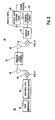
Figure 2 is a simplified transmitter and an efficient joint detection receiver.
-
Figure 3 is an illustration of a communication burst.
-
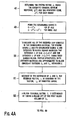
Figures 4a and 4b are a flow chart of a preferred embodiment for efficient joint detection.
-
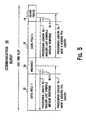
Figure 5 is an illustration of a data burst indicating extended processing areas.
-
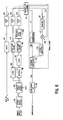
Figure 6 is a block diagram of a preferred implementation of efficient joint detection.
-
Figure 7 is a simplified receiver having multiple antennas.
-
Figure 8 is a simplified receiver sampling the received signal using fractional sampling.
-
Figure 9 is a simplified receiver having multiple antennas and using fractional sampling.
-
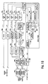
Figure 10 is a block diagram of a preferred implementation of efficient joint detection for fractional sampling or receive diversity.
-
DETAILED DESCRIPTION OF THE PREFERRED EMBODIMENT(S)
-
Figure 2 illustrates a simplified transmitter 26 and receiver 28 using efficient joint detection in a TDD/CDMA communication system, although efficient joint detection is applicable to other systems, such as FDD/CDMA. In a typical system, a transmitter 26 is in each UE 14 and multiple transmitting circuits 26 sending multiple communications are in each base station 12. The joint detection receiver 28 may be at a base station 12, UEs 14 or both.
-
The transmitter 26 sends data over a wireless radio channel 30. A data generator 32 in the transmitter 26 generates data to be communicated to the receiver 28. A modulation/spreading/training sequence insertion device 34 spreads the data with the appropriate code(s) and makes the spread reference data time-multiplexed with a midamble training sequence in the appropriate assigned time slot, producing a communication burst or bursts.
-
A typical communication burst 16 has a midamble 20, a guard period 18 and two data fields 22, 24, as shown in Figure 3. The midamble 20 separates the two data fields 22, 24 and the guard period 18 separates the communication bursts to allow for the difference in arrival times of bursts transmitted from different transmitters 26. The two data fields 22, 24 contain the communication burst's data.
-
The communication burst(s) are modulated by a modulator 36 to radio frequency (RF). An antenna 38 radiates the RF signal through the wireless radio channel 30 to an antenna 40 of the receiver 28. The type of modulation used for the transmitted communication can be any of those known to those skilled in the art, such as quadrature phase shift keying (QPSK) or M-ary quadrature amplitude modulation (QAM).
-
The antenna 40 of the receiver 28 receives various radio frequency signals. The received signals are demodulated by a demodulator 42 to produce a baseband signal. The baseband signal is sampled by a sampling device 43, such as one or multiple analog to digital converters, at the chip rate of the transmitted bursts. The samples are processed, such as by a channel estimation device 44 and an efficient joint detection device 46, in the time slot and with the appropriate codes assigned to the received bursts. The channel estimation device 44 uses the midamble training sequence component in the baseband samples to provide channel information, such as channel impulse responses. The channel information is used by the efficient joint detection device 46 to estimate the transmitted data of the received communication bursts as soft symbols.
-
The efficient joint detection device 46 uses the channel information provided by the channel estimation device 44 and the known spreading codes used by the transmitter 26 to estimate the data of the desired received communication burst(s).
-
Although efficient joint detection is explained using the third generation partnership project (3GPP) universal terrestrial radio access (UTRA) TDD system as the underlying communication system, it is applicable to other systems. That system is a direct sequence wideband CDMA (W-CDMA) system, where the uplink and downlink transmissions are confined to mutually exclusive timeslots.
-
The receiver 28 receives a total of K bursts that arrive simultaneously, within one observation interval. For the 3GPP UTRA TDD system, each data field of a time slot corresponds to one observation interval. For a frequency division duplex (FDD) CDMA system, the received signals are continuous, i.e., not in bursts. To handle the continuous signals, FDD systems divide the received signals into time segments prior to applying efficient joint detection.
-
A code used for a kth burst is represented as c (k) . The K bursts may originate from K different transmitters or for multi-code transmissions, less than K different transmitters.
-
Each data field of a communication burst has a predetermined number of transmitted symbols, Ns. Each symbol is transmitted using a predetermined number of chips, which is the spreading factor, Q. Accordingly, each data field has Ns x Q chips. After passing through the wireless radio channel, which can introduce a delay spread of up to W-1 chips, the observation interval at the receiver is of length Q x Ns + W - 1 chips.
-
The symbol response vector
b (k) as the convolution of the channel response vector
h (k) with the corresponding spreading code
c (k) is per
Equation 1.
- ○ denotes the convolutional operator. The length of b (k) is SF+ W - 1.
-
Using the symbol response vectors, the system matrix
A is defined as per
Equation 2.
-
The size of the matrix is (Ns · SF + W - 1)×Ns · K. A is a block Topleitz matrix.
-
Block
B is defined as per Equation 3.
The received vector sampled at the chip rate can be represented by Equation 4.
-
The size of vector r is (Ns · SF + W - 1) by 1. This size corresponds to the observation interval.
-
Data vector
d of size
Ns ·
K by 1 has the form of Equation 5.
-
The sub-vector
d n of size
K by 1 is composed of the
nth symbol of each user and is defined as Equation 6.
-
The vector n of size (Ns · SF + W - 1) by 1 is the background noise vector and is assumed to be white.
-
Determining
d using an MMSE solution is per Equation 7.
(·)
H represents the hermetian function (complex conjugate transpose). The covariance matrix of the system matrix
R for a preferred MMSE solution is per Equation 8.
σ
2 is the noise variance, typically obtained from the
channel estimation device 44, and
I is the identity matrix.
-
Using block circulant approximation and block DFT using PFA-FFTs,
d in Equation 7 can be determined per Equation 9.
F(·) and
F -1(·) indicate the block-DFT function and the inverse block-DFT, respectively. The derivation of the block diagonal matrices Λ and Λ
A is described subsequently. Instead of directly solving Equation 9, Equation 9 can be solved using the LU decomposition and the forward and backward substitution of the main diagonal block of Λ. Alternately, Equation 9 can be solved using Cholesky decomposition.
-
Figure 4 is a flowchart for a preferred method of determining the data vector
d using fast joint detection. The system matrix
A is determined using the estimated channel response vector
h (k) and the spreading code
c (k) for each burst, 48.
R, the covariance matrix of the system matrix, is formed, 49. The system matrix
A and its covariance matrix
R are extended block square matrices. The extended
A is of size
D·
Q by
D·
K and the extended
R is of size
D·
K by D·
K, respectively.
D is chosen as per
Equation 10.
Both extended matrices are approximated to block circulant matrices,
A c and
R c , 50. Because of the extension of
A and
R, the received vector,
r , is extended to the vector
r c of size
D·
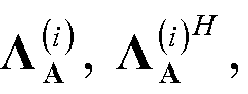
SF x 1 by inserting zeros, 51. The block-diagonal matrix, Λ , is determined by taking a block DFT using PFA-FFT of the first block column of
R c , 52.
-
The block DFT of matched filtering Error! Objects cannot be created from editing field codes. is approximated by Error! Objects cannot be created from editing field codes.. It is calculated by taking a block DFT using PFA-FFT of
A c and
r c, 53. Due to the block-diagonal structure of Λ and Λ
A , the blocks
F(
d )
(i),
i =1, ...,
D, are of size
K by 1 in
F(
d ). They are determined by performing on the main diagonal blocks, Error! Objects cannot be created from editing field codes.of Error! Objects cannot be created from editing field codes., LU decomposition, Error! Objects cannot be created from editing field codes., forward substitution,
55, and backward substitution, Error! Objects cannot be created from editing field codes., 56. Error! Objects cannot be created from editing field codes. is a lower triangular matrix. Error! Objects cannot be created from editing field codes. is a an upper triangular matrix.
is the
ith main diagonal block of size
SF by
K in Λ
A and
F(
r c )
(i) is the
ith block of size
Q x 1 in
F(
r c ). Λ
A is the block DFT using PFA-FFT of the first column of
A c and
F(
r c ) is the block DFT using PFA-FFT of the vector,
r c . The estimated data vector,
d , is determined by a inverse block-DFT of
F(
d), 57.
-
Although Equation 9 is a MMSE based solution, fast joint detection can be applied to other approaches, such as a zero forcing approach as per Equation 11.
As shown in Equation 11, in the zero forcing solution, the σ
2 I term is deleted from Equation 8. The following is a derivation for the MMSE solution, although an analogous derivation can be used for a zero forcing solution.
-
To reduce the complexity in determining F(A H r ), a block DFT using PFA-FFT approach taking advantage of the block-Toeplitz structure of A may be used as shown in Equation 2. First, by repeating B, we extend A to a block-square matrix of size D·Q × D·K , to use all of the chip symbols in the observation interval. The extended A is composed of D 2 blocks of size Q x K. The extended A is approximated to the block-circulant matrix A c.
-
A c can be decomposed into three matrices per Equation 12.
F (n) =
F Ⓧ
I n is a block DFT using PFA-FFT matrix of size
D·
n by
D·
n. Ⓧ denotes a kronecker product.
I n is an identity matrix of size
n x
n and
F is a DFT matrix of size
D x
D, whose elements
fil ,
i and
l = 1, 2, ...,
D are per Equation 13.
D is the length of the DFT and
F H F =
I. I is an identity matrix of size
D x
D.
-
The block diagonal matrix Λ
A is of size
D·
Q×
D·
K and has the form per Equation 14.
-
Each of its entries
i = 1, 2, ...,
D, is a
Q by
K block per Equation 15.
-
Alternatively, the main diagonal blocks,
i = 1, 2, ...,
D, can be computed by, per
Equation 16.
A c (:, 1:
K) denotes the first block column of
A c . Namely, the first Kcolumns of
A c .
F (SF) A c (:, 1:
K) can be calculated by
Q·
K parallel non-block DFTs of length
D, using PFA-FFTs.
-
Due to the extention of A, the received vector r is also extended by inserting zeros, becoming vector r c of size D·Q by 1.
-
Using the above,
F(
A H r ) is approximated to
It can be written as Equation 17.
-
The covariance matrix
R of size
Ns ·
K ×
Ns ·
K has the block-square matrix form shown in
Equation 18.
L is defined per Equation 19.
Each entry,
R i , in the
R matrix is a
K by
K block and
0 is a
K by
K zero matrix. Due to the size of the extended
A, the matrix
R is also extended to size
D·
K by
D·
K by inserting zeros.
-
The extended
R is approximated to a block-circulant matrix,
R c, of size
D·
K by
D·
K per
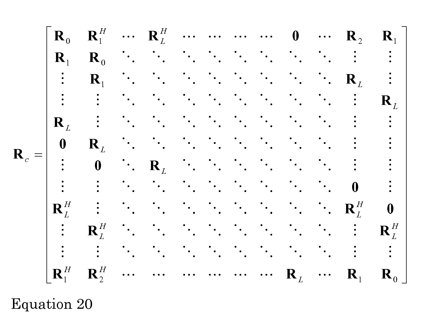
Equation 20.
-
The block circulant matrix
R c , is decomposed into three matrices per Equation 21.
F (K) =
F Ⓧ
I K is a block DFT using PFA-FFT matrix of size
D·
K ×
D·
K. Ⓧ denotes a Kronecker product.
I K is an identity matrix of size
K x
K and
F is a DFT matrix of size
D x
D as described in Equation 13.
-
The block diagonal matrix Λ of size
D·K by
D·
K has the form per
Equation 22.
Each of its entries, Λ
(i),
i = 1, 2, ...,
D, is a
K by
K block, per Equation 23A.
Alternatively, the main diagonal blocks, Λ
(i),
i = 1, 2, ...,
D, can be computed per Equation 23B.
R c (:, 1:
K) denotes the first block column of
R c . Namely, the first
K columns of
R c .
F (K) R c (:, 1:
K) can be calculated by
K 2 parallel non-block DFTs of length
D, using PFA_FFTs.
-
The estimated data vector,
d , in Equation 7 is preferably approximated per Equation 24A.
The block diagonal matrix Λ
-1 is per Equation 24B.
The inversion of Λ requires an inversion of K x K matrices, Λ
(i),
i = 1, 2, ...,
D.
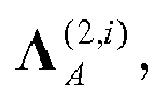
-
Equation 24A can be rewritten as Equation 25.
F(
r c ) is per Equations 26A and 26B.
Due to the block-diagonal structure of Λ
-1 and
Equation 25 can be efficiently calculated as follows. The terms of Equation 25 are partitioned into
D blocks, as per Equation 27.
-
Each block in Equation 27 is solved separately, per
Equation 28.
-
F(
d )
(i) is a
K by 1 vector. Λ
(i) is a
K by
K matrix, per
Equation 22.
is an
Q by
K matrix, per Equation 14.
F(
r c )
(i) is an
Q by 1 vector and is composed of elements (1+(
i-1)
Q) through (
i·Q) of
F(
r c ).
-
To avoid the direct inversion of Λ
(i),
Equation 28 can be solved by using
LU decomposition and forward and backward substitution.
Equation 28 is rewritten per Equation 29.
Error! Objects cannot be created from editing field codes. is a lower triangular matrix and Error! Objects cannot be created from editing field codes.is an upper triangular matrix.
-
Using
LU decomposition,
Equation 28 is represented as, per Equation 31.
F(
d )
(i) in Equation 31 is solved by forward substitution, per
Equation 32, and backward substitution, per Equation 33.
-
Finally,
d is determined for all blocks as per
Equation 34.
-
Figure 6 is a block diagram of a preferred implementation of efficient joint detection in a TDD/CDMA system. Using the received vector, r, r c is formed by inserting zeros, then a block DFT 100 of r c is performed per Equation 26, to produce F( r c).
-
Using the received training sequences, the channel impulse responses for each transmitted burst, h (k) , is determined by an estimate channel response block 102. Using each channelization code, c (k) and the channel impulse response, h (k), the system matrix, A, is determined by compute block matrix A block 104 per Equation 2.
-
To determine ΛA, the system matrix A is extended by extend block 132, to use all received chips in the observation interval. The first block column of the block-circulant matrix A c is determined by selecting the first K columns of the extended A matrix by first block column block 114. By taking a block DFT using PFA-FFT 118 using PFA-FFT, ΛA is determined.
-
To determine Λ , R is first determined by compute R block 140. For an MMSE solution, R = A H A + σ2 I is used; for a zero forcing solution, R = A H A is used. Due to the size of the extended A, R is also extended by extend block 134.The first block column of the extended R matrix is determined by selecting the first K columns of the extended R matrix by first block column block 108. The first block column of the extended R matrix is circularized by a circularize block column block 110. It becomes the first block column of a block-circulant R c . By taking a block DFT using PFA-FFT by block DFT block 112, Λ is determined.
-
To efficiently compute the estimated data vector
d , Λ
A , Λ, and
F( r c) are divided into blocks
Λ
(i), and
F(
r c )
(i),
i = 1,2, ...,
D, respectively, exploiting the block-diagonal structures of Λ
A and Λ, by partition block 136. The complex conjugate transpose of
is determined by a
transpose block 130. A
multiplier 128 multiplies
by
F(
r c )
(i). Λ
(i) is decomposed using
LU decomposition by a
LU decomposition block 126, per
Equation 30. By performing forward and backward substitution, per Equations 31-33, using forward and backward substitution blocks 124 and 122, respectively,
F(
d )
(i) is determined. By repeating the
LU decomposition and forward and backward substitution
D times,
F(
d ) is found. Taking a inverse block DFT using PFA-FFT of
F(
d ) by block
inverse DFT block 120,
d is estimated.
-
Figures 7, 8 and 9 are simplified diagrams of receivers applying efficient joint detection to multiple reception antennas and/or fractional (multiple chip rate) sampling. A receiver 28 with multiple reception antennas is shown in Figure 7. Transmitted bursts are received by each antenna 401 to 40m (40). Each antennas' version of the received bursts are reduced to baseband, such as by demodulators 421 to 42m. The baseband signals for each antenna are sampled by sampling devices 431 to 43m to produce a received vector, r 1 to r m , for each antenna 40. The samples corresponding to the midamble are processed by a channel estimation device 144 to produce channel response matrices, H1 to Hm, for each antenna 40. The received data vector, d, is determined by an efficient joint detection device 142 using the received vectors and the channel response matrices.
-
A receiver 28 sampling using fraction sampling is shown in Figure 8. Transmitted bursts are received by the antenna 40. The received bursts are reduced to baseband, such as by a demodulator 42. The baseband signal is sampled by a sampling device 43 to produce factional samples as received vectors, r 1 to r m . Each received vector represents chip rate samples sampled at a fraction of a chip offset. To illustrate, for twice the chip rate sampling, two received vectors r 1 and r 2 are produced. Each of those vectors has samples spaced by half a chip in time. Samples corresponding to the midamble are processed by a channel estimation device 144 to produce channel response matices, H 1 to H m, for each set of fractional samples. The received data vector, d, is determined by an efficient joint detection device 142 using the received vectors and the channel response matrices.
-
A receiver 28 with multiple reception antennas and using fractional sampling is shown in Figure 9. Transmitted bursts are received by each antenna 401 to 40i (40). Each antennas' version of the received bursts are reduced to baseband, such as by demodulators 421 to 42i. The baseband signals for each antenna are sampled by sampling devices 431 to 43j to produce a received vectors, r 1 to r m . The received vectors for each antenna correspond to each multiple of the chip rate samples. The samples corresponding to the midamble are processed by a channel estimation device 144 to produce channel response matices, H 1 to H m, for each antenna's fractional samples. The received data vector, d , is determined by an efficient joint detection device 142 using the received vectors and the channel response matrices.
-
In applying efficient joint detection to either receive diversity, fractional sampling or both, the received communication bursts are viewed as M virtual chip rate received bursts. To illustrate, for twice the chip rate sampling and two antenna receive diversity, the received bursts are modeled as four (M=4) virtual chip rate received bursts.
-
Each received burst is a combination of K transmitted bursts. Each of the K transmitted bursts has its own code. The channel impulse response vector of the kth out of K codes and the mth out of the M virtual received bursts is h (k,m) . h (k,m) has a length W and is estimated from the midamble samples of the burst of the kth code of the mth virtual received burst.
-
Each of the
N data symbols of the burst of the
kth code is per Equation 35.
-
The code of the
kth burst is per
Equation 36.
-
The symbol response of the
kth code's contribution to the
mth virtual burst,
b (k,m) is per Equation 37.
-
The length of the symbol response is
Q+
W-1.
Q is the spreading factor. The system matrix,
A(m) , for each
mth received burst is per
Equation 38.
-
Each block
B (m) is of size (
Q+
W-1) by
K and is per Equation 39.
-
The overall system matrix
A is per
Equation 40.
-
As shown in
Equation 38, each sub-system matrix
A (m) is block Toeplitz. The overall received vector of the
M virtual bursts is of size
M(
NQ+
W-1) and is per Equation 41.
The
mth received vector
r m is of size
NQ+
W-1 by 1.
-
Equation 42 is a model for the overall received vector.
n is the noise variance.
-
Each
mth received virtual burst is per
Equation 43.
n m is the noise variance for the
mth received virtual burst.
-
To solve for the data vector
d in
Equation 42, a block linear equalizer with either a zero forcing or minimum mean square error (MMSE) approach may be used per
Equation 44.
R is the covariance matrix.
-
For a zero forcing solution,
R is per Equation 45.
-
For a MMSE solution,
R is per
Equation 46.
-
The covariance matrix for either the zero forcing or MMSE solution is a block Toeplitz. To apply a discrete Fourier transform to the block-Toeplitz A (m) matix, a block-circulant approximation of A (m), A c (m) is used. To make A (m) a block-square matrix, A (m) is extended. The extended A (m) matrix is then approximated to a block circulant matrix A c (m).
-
The
A c (m) matrix is composed of
D by
D blocks. Each block is of size
Q by
K. Accordingly, the size of
A c (m) becomes
DQ by
DK. To include all the elements of
A (m),
D is chosen to be an integer larger than
D min as determined per Equation 47.
┌·┐ represents a round up to an integer function.
-
The covariance matrix R is a block-square matrix of size NK by NK with blocks of size K by K. For R to be compatible with the extended A c (m) matrix, R is extended to the size DK by DK by zero-padding and approximating the extended R to a block circulant covariance matrix R c. For the received vector, r (m), to be compatible with A c (m) and R c, r (m) is extended to a DQ by 1 vector, r c (m) by zero padding.
-
After extending the received vectors,
r (m), the over all received vector is per
Equation 48.
-
Each block-circulant matrix
A c (m) is diagonalized to a block-diagonal matrix by block discrete Fourier transform matrices per
Equation 49.
-
F (Q) is per
Equation 50.
-
F (K) is per
Equation 51.
F is a discrete Fouriertrans form matrix of size
D by
D and is an
n by
n identity matrix. Λ
A (m) is a block diagonal matrix of the form of
Equation 52.
-
ΛA (l,m) for l = 1,...,D, and m=1,...,M is a non-zero block of size Q by K. 0 is a zero matrix of size Q by K having all zero elements.
-
Λ
A (l,m) is alternately computed per
Equation 53.
-
(:,1:K) is the first block column of
The first block column having
K columns. To determine
preferably
(:,1K) is determined by
QK parallel non-block DFTs of length
D, using PFA-FFTs. The block circulant matrix
R c is also preferably diagonalized to the block diagonal matrix Λ
R by a block DFT matrix
F (K) =
F ⊗
I K as per Equation 54.
-
The block diagonal matrix Λ
R is composed by blocks
l = 1, ...,
D of size
K by
K in its main diagonal block, per
Equation 55.
-
Another approach to determine Λ
R is per
Equation 56.
R c(:, 1:
K) is the first block column of
R c .
F (K) R c (:, 1:K) is preferably determined using
K 2 parallel non-block DFTs of length
D. In one implementation, the
K 2 parallel non-block DFTs are implemented using
K 2 parallel non-block prime factor algorithm fast Fourier transforms (PFA-FFTs) of length
D.
-
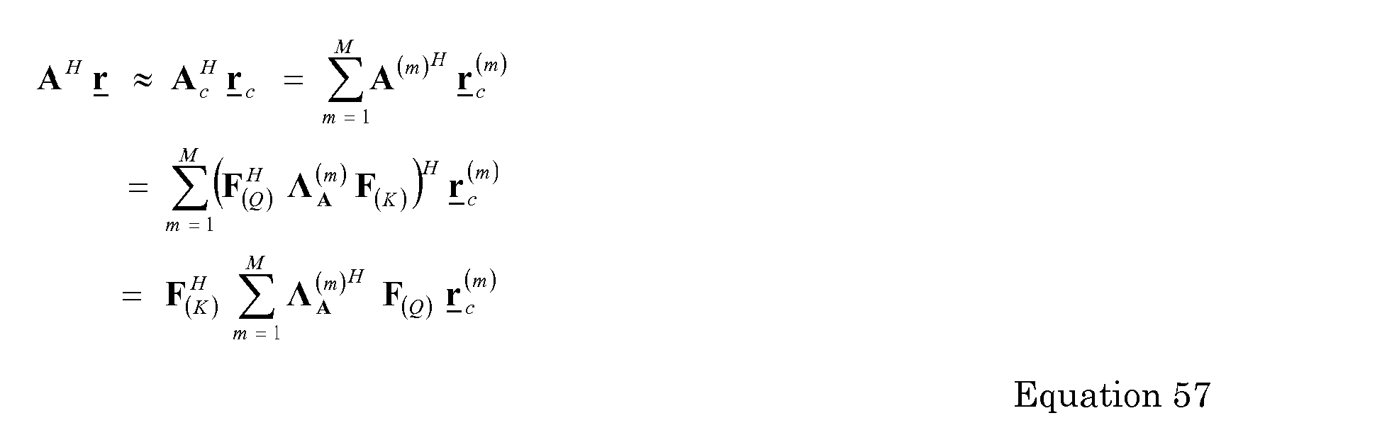
Preferably to perform the block equalization of
Equation 44, the matched filtering is approximated per
Equation 57.
-
The block-diagonalization of
is per Equation 58.
-
The estimation of the data vector,
d̂ , is per Equation 59.
-
The vector
y is of size DK by 1 and is per Equation 60.
y (l),
l = 1, ...
D is a vector of size
K by 1.
-
Preferably to determine
y ,
is determined using
Q parallel non-block DFTs of a length
D. In one implementation , the
Q parallel non-block DFTs are implemented using
Q parallel non-block PFA-FFTs of length
D.
is a block diagonal matrix having blocks of size
K by
K in the main diagonal and is per Equation 61.
Each
l = 1, ...,
D, is a block of size
K by
K.
-
Preferably using the block diagonal structure of
,
y (l) is determined by the Cholesky decomposition of
and forward and backward substitution in parallel. Alternately,
is directly inverted.
-
To perform the Cholesky decomposition, a vector
is divided into
D blocks of a size
K by 1, per Equation 62.
-
A Cholesky factor
G (l) of
is determined using a factorization, per Equation 63.
-
Using the Cholesky factor
G (l), each
y (l) is determined by forward and backward substitution separately per Equations 64, 65 and 66.
-
By performing a block inverse DFT of y , the data vector d is estimated as d̂ . Preferably, the block inverse DFT is implemented using K parallel non-block inverse PFA-FFTs of a length D.
-
Figure 10 is a block diagram of a preferred implementation of efficient joint detection in a TDD/CDMA system. Although
Figure 10 illustrates using two sets of samples, the figure can be extended to other multiple sets. Using the received vector for each set of chip rate samples,
r 1 and
r 2 , r c (1) and
r c (2) is formed by inserting zeros, by Extend blocks 232
1 and 232
2, respectively. A block DFT 200
1 and 200
2 using PFA-FFT of
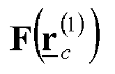
r c (1) and
r c (2) is then performed, to produce
and
-
Using the received training sequences, the channel impulse responses for each chip rate version of each transmitted burst, h (k)(1) and h (k)(2), is determined by estimate channel response blocks 2021 and 2022. Using each channelization code, c (k) and the channel impulse response, h (k)(1) and h (k)(2), each system matrix, A (1) and A (2) , is determined by compute sub-system matrix blocks 2041 and 2042 per Equations 37 and 38.
-
To determine
and
each system matrix,
A (1) and
A (2) , is extended by extend
blocks 231
1 and 231
2. The first block column of each block-circulant matrix,
A (1) and
A (2) , is determined by selecting the first
K columns of the extended
A (m) matrix by first block column blocks 214
1 and 214
2. By taking
block DFTs 218
1 and 218
2,
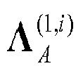
and
are determined using a PFA-FFT.
-
To determine Λ
R, the first block column of
R is determined by compute first block
column R block 240. The first column of
R is extended by extend
block 234. The first block column of the extended
R is determined by a first block
column determining device 208. The first block column of the extended
R matrix is circularized,
R c , by a circularize
block column block 210. By taking a block DFT by
block DFT block 212,
is determined using a PFA-FFT.
-
To efficiently compute the estimated data vector
d , each of
and
and
as well as Λ
R are used. Each of
and Λ
R is divided into D blocks, by
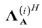
partition block 236. The complex conjugate transpose of each of
and
and
where i is the i
th block, is determined by
transpose blocks 230, 231. A
multiplier 228 multiplies
by
A
multiplier 229 multiplies
by
A
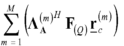
summer 225 sums the multiplied results per Equation 62.
is decomposed using
Cholesky decomposition 226, per Equation 63. By performing forward and backward substitution, per Equations 65 and 66, using forward and backward substitution blocks 224 and 222, respectively,
F(
d ) is determined. Taking an inverse block DFT using PFA-FFT of
F(
d ) by block inverse DFT block 220 using a PFA-FFT,
d̂ is estimated.
ITEMISED LIST
-
- Item 1. A method for detecting data from K data signals transmitted over a shared spectrum in a code division multiple access format, the method comprising:
- receiving and sampling a combined signal over the shared spectrum as a plurality of received vector versions, the combined signal including the K transmitted data signals;
- producing a plurality of system matrices and an associated covariance matrix using codes and estimated impulse responses of the K data signals, each system matrix corresponding to a received vector version;
- extending and approximating the system and covariance matrices as block circulant matrices;
- determining a diagonal matrix of each of the extended and approximated system and covariance matrices, using a block column of the extended and approximated system and covariance matrices;
- extending and taking a Fourier transform of each received vector version;
- taking products of the diagonal matrices and the extended received vector versions;
- summing the products; and
- estimating data of the K data signals using an inverse Fourier transform and the summed products.
- Item 2. The method of item 1 wherein the Fourier transforms are performed using a prime factor algorithm fast Fourier transform.
- Item 3. The method of item 1 wherein each received vector version corresponds to a different reception antenna.
- Item 4. The method of item 1 wherein the combined signal is sampled at a multiple of a chip rate of the K data signals and each received vector version corresponds to a different chip rate multiple.
- Item 5. The method of item 1 wherein the K data signals are received over a plurality of antennas and sampled at a multiple of a chip rate of the K data signals and each received vector version corresponds to a different antenna and chip rate multiple combination.
- Item 6. The method of item 1 further comprising partitioning the diagonal matrices into a plurality of partitions.
- Item 7. The method of item 1 wherein the estimating data of the K data signals includes performing LU decomposition , forward substitution and backward substitution.
- Item 8. The method of item 1 wherein the estimating data of the K data signals includes performing Cholesky decomposition, forward substitution and backward substitution.
- Item 9. The method of item 1 wherein LU decomposition or Cholesky decomposition is performed on the diagonal of the covariance matrix.
- Item 10. A user equipment for detecting data from K data signals transmitted over a shared spectrum in a code division multiple access format, the user equipment comprising:
- means for receiving and sampling a combined signal over the shared spectrum as a plurality of received vector versions, the combined signal including the K transmitted data signals;
- means for producing a plurality of system matrices and an associated covariance matrix using codes and estimated impulse responses of the K data signals, each system matrix corresponding to a received vector version;
- means for extending and approximating the system and covariance matrices as block circulant matrices;
- means for determining a diagonal matrix of each of the extended and approximated system and covariance matrices, using a block column of the extended and approximated system and covariance matrices;
- means for extending and taking a Fourier transform of each received vector version;
- means for taking products of the diagonal matrices and the extended received vector versions;
- means for summing the products; and
- means for estimating data of the K data signals using an inverse Fourier transform and the summed products.
- Item 11. The user equipment of item 10 wherein the Fourier transforms are performed using a prime factor algorithm fast Fourier transform.
- Item 12. The user equipment of item 10 wherein each received vector version corresponds to a different reception antenna.
- Item 13. The user equipment of item 10 wherein the combined signal is sampled at a multiple of a chip rate of the K data signals and each received vector version corresponds to a different chip rate multiple.
- Item 14. The user equipment of item 10 wherein the K data signals are received over a plurality of antennas and sampled at a multiple of a chip rate of the K data signals and each received vector version corresponds to a different antenna and chip rate multiple combination.
- Item 15. The user equipment of item 10 further comprising means for partitioning the diagonal matrices into a plurality of partitions.
- Item 16. The user equipment of item 10 wherein the estimating data of the K data signals includes performing LU decomposition , forward substitution and backward substitution.
- Item 17. The user equipment of item 10 wherein the estimating data of the K data signals includes performing Cholesky decomposition, forward substitution and backward substitution.
- Item 18. The user equipment of item 10 wherein LU decomposition is performed on the diagonal of the covariance matrix.
- Item 19. The user equipment of item 10 wherein Cholesky decomposition is performed on the diagonal of the covariance matrix.
- Item 20. A user equipment for detecting data from K data signals transmitted over a shared spectrum in a code division multiple access format, the user equipment comprising:
- an antenna and a sampling device for receiving a combined signal over the shared spectrum as a plurality of received vector versions, the combined signal including the K transmitted data signals;
- a plurality of compute sub-system matrix blocks for producing a plurality of system matrices using estimated impulse responses of the K data signals, each system matrix corresponding to a received vector version;
- a compute covariance matrix block for producing a covariance matrix associated with the system matrices;
- a plurality of extension blocks for extending the system and covariance matrices;
- a plurality of first block column devices for approximating the extended system and covariance matrices as block circulant matrices;
- a plurality of block Fourier transform devices for determining a diagonal matrix of each of the extended and approximated system and covariance matrices, using the block column of the extended and approximated system and covariance matrices;
- an extension device for extending each received vector version;
- a block Fourier transform device for taking a Fourier transform of each received vector version;
- a plurality of multipliers for taking products of the diagonal matrices and the extended received vector versions;
- a summer for summing the products; and
- a block inverse Fourier transform device for estimating data of the K data signals using an inverse Fourier transform and the summed products.
- Item 21. The user equipment of item 20 wherein the Fourier transforms are performed using a prime factor algorithm fast Fourier transform.
- Item 22. The user equipment of item 20 wherein each received vector version corresponds to a different reception antenna.
- Item 23. The user equipment of item 20 wherein the combined signal is sampled at a multiple of a chip rate of the K data signals and each received vector version corresponds to a different chip rate multiple.
- Item 24. The user equipment of item 20 wherein the K data signals are received over a plurality of antennas and sampled at a multiple of a chip rate of the K data signals and each received vector version corresponds to a different antenna and chip rate multiple combination.
- Item 25. The user equipment of item 20 further comprising partitioning device for partitioning the diagonal matrices into a plurality of partitions.
- Item 26. The user equipment of item 20 further comprising a LU decomposition device for performing LU decomposition on the diagonal of the covariance matrix and a forward substitution and a backward substitution devices for producing an inverse Fourier transform of the estimated data vector.
- Item 27. The user equipment of item 20 further comprising a Cholesky decomposition device for performing Cholesky decomposition on the diagonal of the covariance matrix and a forward substitution and a backward substitution devices for producing an inverse Fourier transform of the estimated data vector.
- Item 28. A base station for detecting data from K data signals transmitted over a shared spectrum in a code division multiple access format, the base station comprising:
- means for receiving and sampling a combined signal over the shared spectrum as a plurality of received vector versions, the combined signal including the K transmitted data signals;
- means for producing a plurality of system matrices and an associated covariance matrix using codes and estimated impulse responses of the K data signals, each system matrix corresponding to a received vector version;
- means for extending and approximating the system and covariance matrices as block circulant matrices;
- means for determining a diagonal matrix of each of the extended and approximated system and covariance matrices, using a block column of the extended and approximated system and covariance matrices;
- means for extending and taking a Fourier transform of each received vector version;
- means for taking products of the diagonal matrices and the extended received vector versions;
- means for summing the products; and
- means for estimating data of the K data signals using an inverse Fourier transform and the summed products.
- Item 29. The base station of item 28 wherein the Fourier transforms are performed using a prime factor algorithm fast Fourier transform.
- Item 30. The base station of item 28 wherein each received vector version corresponds to a different reception antenna.
- Item 31. The base station of item 28 wherein the combined signal is sampled at a multiple of a chip rate of the K data signals and each received vector version corresponds to a different chip rate multiple.
- Item 32. The base station of item 28 wherein the K data signals are received over a plurality of antennas and sampled at a multiple of a chip rate of the K data signals and each received vector version corresponds to a different antenna and chip rate multiple combination.
- Item 33. The base station of item 28 further comprising means for partitioning the diagonal matrices into a plurality of partitions.
- Item 34. The base station of item 28 wherein the estimating data of the K data signals includes performing LU decomposition , forward substitution and backward substitution.
- Item 35. The base station of item 28 wherein the estimating data of the K data signals includes performing Cholesky decomposition, forward substitution and backward substitution.
- Item 36. The base station of item 28 wherein LU decomposition is performed on the diagonal of the covariance matrix.
- Item 37. The base station of item 28 wherein Cholesky decomposition is performed on the diagonal of the covariance matrix.
- Item 38. A base station for detecting data from K data signals transmitted over a shared spectrum in a code division multiple access format, the base station comprising:
- an antenna and a sampling device for receiving a combined signal over the shared spectrum as a plurality of received vector versions, the combined signal including the K transmitted data signals;
- a plurality of compute sub-system matrix blocks for producing a plurality of system matrices using estimated impulse responses of the K data signals, each system matrix corresponding to a received vector version;
- a compute covariance matrix block for producing a covariance matrix associated with the system matrices;
- a plurality of extension blocks for extending the system and covariance matrices;
- a plurality of first block column devices for approximating the extended system and covariance matrices as block circulant matrices;
- a plurality of block Fourier transform devices for determining a diagonal matrix of each of the extended and approximated system and covariance matrices, using the block column of the extended and approximated system and covariance matrices;
- an extension device for extending each received vector version;
- a block Fourier transform device for taking a Fourier transform of each received vector version;
- a plurality of multipliers for taking products of the diagonal matrices and the extended received vector versions;
- a summer for summing the products; and
- a block inverse Fourier transform device for estimating data of the K data signals using an inverse Fourier transform and the summed products.
- Item 39a. The base station of item 38 wherein the Fourier transforms are performed using a prime factor algorithm fast Fourier transform.
- Item 39b. The base station of item 38 wherein each received vector version corresponds to a different reception antenna.
- Item 40. The base station of item 38 wherein the combined signal is sampled at a multiple of a chip rate of the K data signals and each received vector version corresponds to a different chip rate multiple.
- Item 41. The base station of item 38 wherein the K data signals are received over a plurality of antennas and sampled at a multiple of a chip rate of the K data signals and each received vector version corresponds to a different antenna and chip rate multiple combination.
- Item 42. The base station of item 38 further comprising partitioning device for partitioning the diagonal matrices into a plurality of partitions.
- Item 43. The base station of item 38 further comprising a LU decomposition device for performing LU decomposition on the diagonal of the covariance matrix and a forward substitution and a backward substitution devices for producing an inverse Fourier transform of the estimated data vector.
- Item 44. The base station of item 38 further comprising a Cholesky decomposition device for performing Cholesky decomposition on the diagonal of the covariance matrix and a forward substitution and a backward substitution devices for producing an inverse Fourier transform of the estimated data vector.
- Item 45. A method for receiving a plurality of data signals transmitted over a shared spectrum in a code division multiple access communication system, the method comprising:
- receiving and sampling a combined signal having the plurality of transmitted data signals to produce a received vector;
- determining a channel response for the plurality of transmitted data signals;
- determining a system response matrix using the determined channel response and codes of the transmitted data signals;
- determining a covariance matrix using the system response matrix;
- extending the received vector, the system response matrix and the determined covariance matrix;
- taking a block discrete Fourier transform of a block column of the extended covariance matrix
- taking a block discrete Fourier transform of a block column of the system response matrix;
- taking a block discrete Fourier transform of the received vector; and
- determining an extended data vector using the block discrete Fourier transforms.
- Item 46. The method of item 45 further comprising partitioning the block discrete Fourier transforms.
- Item 47. The method of item 45 further comprising performing LU decomposition on the block Fourier transforms.
- 48. A user equipment for detecting data from K data signals transmitted over a shared spectrum in a code division multiple access format, the user equipment comprising:
- an antenna and a sampling device for receiving and sampling a combined signal having the plurality of transmitted data signals to produce a received vector;
- a channel estimation device for determining a channel response for the plurality of transmitted data signals;
- a compute block matrix device for determining a system response matrix using the determined channel response and codes of the transmitted data signals;
- a compute covariance matrix device for determining a covariance matrix using the system response matrix;
- a plurality of extend devices for extending the received vector, the system response matrix and the determined covariance matrix;
- a block discrete Fourier transform device for taking a block discrete Fourier transform of a block column of the extended covariance matrix
- a block discrete Fourier transform device for taking a block discrete Fourier transform of a block column of the system response matrix;
- a block discrete Fourier transform device for taking a block discrete Fourier transform of the received vector; and
- a circuit for determining an extended data vector using the block discrete Fourier transforms.
- Item 49. The user equipment of item 48 further comprising a partitioning device for partitioning the block discrete Fourier transforms.
- Item 50. The user equipment of item 48 wherein the circuit comprising a LU decomposition device for performing LU decomposition on the block Fourier transforms.
- Item 51. A user equipment for detecting data from K data signals transmitted over a shared spectrum in a code division multiple access format, the user equipment comprising:
- means for receiving and sampling a combined signal having the plurality of transmitted data signals to produce a received vector;
- means for determining a channel response for the plurality of transmitted data signals;
- means for determining a system response matrix using the determined channel response and codes of the transmitted data signals;
- means for determining a covariance matrix using the system response matrix;
- means for extending the received vector, the system response matrix and the determined covariance matrix;
- means for taking a block discrete Fourier transform of a block column of the extended covariance matrix
- means for taking a block discrete Fourier transform of a block column of the system response matrix;
- means for taking a block discrete Fourier transform of the received vector; and
- means for determining an extended data vector using the block discrete Fourier transforms.
- Item 52. The user equipment of item 51 further comprising means for partitioning the block discrete Fourier transforms.
- Item 53. The user equipment of item 51 wherein the means for determining an extended data vector comprising a LU decomposition device for performing LU decomposition on the block Fourier transforms.
- Item 54. A base station for detecting data from K data signals transmitted over a shared spectrum in a code division multiple access format, the base station comprising:
- an antenna and a sampling device for receiving and sampling a combined signal having the plurality of transmitted data signals to produce a received vector;
- a channel estimation device for determining a channel response for the plurality of transmitted data signals;
- a compute block matrix device for determining a system response matrix using the determined channel response and codes of the transmitted data signals;
- a compute covariance matrix device for determining a covariance matrix using the system response matrix;
- a plurality of extend devices for extending the received vector, the system response matrix and the determined covariance matrix;
- a block discrete Fourier transform device for taking a block discrete Fourier transform of a block column of the extended covariance matrix
- a block discrete Fourier transform device for taking a block discrete Fourier transform of a block column of the system response matrix;
- a block discrete Fourier transform device for taking a block discrete Fourier transform of the received vector; and
- a circuit for determining an extended data vector using the block discrete Fourier transforms.
- Item 55. The base station of item 54 further comprising a partitioning device for partitioning the block discrete Fourier transforms.
- Item 56. The base station of item 54 wherein the circuit comprising a LU decomposition device for performing LU decomposition on the block Fourier transforms.
- Item 57. A base station for detecting data from K data signals transmitted over a shared spectrum in a code division multiple access format, the base station comprising:
- means for receiving and sampling a combined signal having the plurality of transmitted data signals to produce a received vector;
- means for determining a channel response for the plurality of transmitted data signals;
- means for determining a system response matrix using the determined channel response and codes of the transmitted data signals;
- means for determining a covariance matrix using the system response matrix;
- means for extending the received vector, the system response matrix and the determined covariance matrix;
- means for taking a block discrete Fourier transform of a block column of the extended covariance matrix
- means for taking a block discrete Fourier transform of a block column of the system response matrix;
- means for taking a block discrete Fourier transform of the received vector; and
- means for determining an extended data vector using the block discrete Fourier transforms.
- Item 58. The base station of item 57 further comprising means for partitioning the block discrete Fourier transforms.
- Item 59. The base station of item 57 wherein the means for determining an extended data vector comprising a LU decomposition device for performing LU decomposition on the block Fourier transforms.