EP2093853B1 - A method and an apparatus for reducing inrush currents for railways - Google Patents
A method and an apparatus for reducing inrush currents for railways Download PDFInfo
- Publication number
- EP2093853B1 EP2093853B1 EP20080151785 EP08151785A EP2093853B1 EP 2093853 B1 EP2093853 B1 EP 2093853B1 EP 20080151785 EP20080151785 EP 20080151785 EP 08151785 A EP08151785 A EP 08151785A EP 2093853 B1 EP2093853 B1 EP 2093853B1
- Authority
- EP
- European Patent Office
- Prior art keywords
- voltage
- breaker
- peak
- transformers
- magnetic remanence
- Prior art date
- Legal status (The legal status is an assumption and is not a legal conclusion. Google has not performed a legal analysis and makes no representation as to the accuracy of the status listed.)
- Active
Links
Images


Classifications
-
- H—ELECTRICITY
- H02—GENERATION; CONVERSION OR DISTRIBUTION OF ELECTRIC POWER
- H02H—EMERGENCY PROTECTIVE CIRCUIT ARRANGEMENTS
- H02H9/00—Emergency protective circuit arrangements for limiting excess current or voltage without disconnection
- H02H9/001—Emergency protective circuit arrangements for limiting excess current or voltage without disconnection limiting speed of change of electric quantities, e.g. soft switching on or off
- H02H9/002—Emergency protective circuit arrangements for limiting excess current or voltage without disconnection limiting speed of change of electric quantities, e.g. soft switching on or off limiting inrush current on switching on of inductive loads subjected to remanence, e.g. transformers
-
- B—PERFORMING OPERATIONS; TRANSPORTING
- B60—VEHICLES IN GENERAL
- B60M—POWER SUPPLY LINES, AND DEVICES ALONG RAILS, FOR ELECTRICALLY- PROPELLED VEHICLES
- B60M3/00—Feeding power to supply lines in contact with collector on vehicles; Arrangements for consuming regenerative power
- B60M3/02—Feeding power to supply lines in contact with collector on vehicles; Arrangements for consuming regenerative power with means for maintaining voltage within a predetermined range
Definitions
- the present invention relates to a method and an apparatus for reducing inrush currents in connection with energizing of transformers in a railway system electrified with an alternating voltage.
- the railway system including a feeder for supplying trains with alternating voltage, a plurality of transformers, and a breaker configured to connect and disconnect the voltage supply to the trains and the transformers.
- a breaker is arranged between a busbar and a contact wire.
- the busbar and the contact wire functions as a feeder for supplying the trains with alternating current.
- Transformer inrush currents are high magnitude currents generated when transformer cores are driven into saturation during energization. These currents have undesirable effect, including potential damage or loss of lifetime to the transformers, protective relay misoperation, and reduced power quality to the railway systems.
- the residual flux which is also called the magnetic remanence, by integration of the winding voltage of the transformer.
- the "induced flux (the integral of the applied voltage) at the instant of energization must be equal to the residual flux. There is no induced flux before energization, but the source voltage has the prospect to create an induced flux. If the source voltage is considered as a virtual flux source, then the optimal instant to energize a transformer is when the "prospective" flux is equal to the residual flux. This provides the basic strategy for controlling closing on single-phase transformers as proposed in this document. However, a problem with the proposed method is that in practice it is difficult to energize the transformer at exactly the point in time when the "prospective" flux is equal to the residual flux.
- the object of the present invention is to provide an improved solution to the above-mentioned problem with remanence in transformers in a railway system upon energization of the railway system.
- this object is achieved with a method as defined in claim 1.
- the method comprises: measuring the alternating voltage supplied to the breaker, measuring the alternating voltage supplied to the trains and the transformers from the breaker, detecting when the breaker disconnects the voltage supply to the trains and the transformers, calculating the magnetic remanence in the transformers based on the measured voltage supplied from the breaker, and determining whether the calculated magnetic remanence is positive or negative.
- the method comprises: connecting the voltage supply at a point in time on or close to a positive peak of the voltage supplied to the breaker if the magnetic remanence is negative, and connecting the voltage supply at a point in time on or close to a negative peak of the voltage supplied to the breaker if the magnetic remanence is positive.
- the railway system is energized at or close to a positive peak of the supplied voltage if the remanence is negative, and at or close to a negative peak of the supplied voltage if the remanence is positive.
- a symmetric magnetization is achieved and accordingly saturation of the transformers is avoided, which otherwise will cause a high inrush current.
- the symmetric magnetization makes the remanence in the transformer to rapidly dissipate. Thus, the risk for the transformers to go into saturation has been significantly reduced and accordingly a high inrush current is avoided.
- the magnetic remanence in the transformers is calculated as the total area of the voltage supplied from the breaker, counted from the last peak voltage before the point in time when the power supply was disconnected until the supplied voltage becomes zero or close to zero.
- the magnetic remanence is determined to be positive if the calculated voltage area is positive and the magnetic remanence is determined to be negative if the calculated voltage area is negative.
- the voltage is preferably calculated by integration of the supplied from the breaker.
- the voltage supply to the supply conductor is connected at a point in time close to and ahead of the peak of the voltage supplied to the breaker.
- the point in time ahead the peak of the voltage supplied is within an interval of 1-4ms.
- said point in time ahead the peak of the voltage is determined based on the size of the calculated magnetic remanence, such that the larger magnetic remanence the longer is the time ahead the peak of the voltage. This embodiment further reduces the inrush current at energizing the railway system.
- Figure 1 shows an apparatus for reducing inrush currents in connection with energizing of transformers in a railway system according to an embodiment of the invention.
- Figure 2 shows an example of the voltage supplied from the breaker before and after the voltage supply has been disconnected.
- Figure 3 shows another example of the voltage supplied from the breaker before and after the voltage supply has been disconnected.
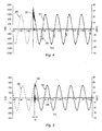
- Figure 4 shows an example of the voltage supplied to the breaker and generated inrush current when the voltage supply is connected at a peak of the voltage.
- Figure 5 shows an example of the voltage supplied to the breaker and generated inrush current when the voltage supply is connected 2-3ms before the peak of the voltage.
- FIG. 1 shows an example of a railway system and an apparatus for reducing inrush currents in the railway system according to an embodiment of the invention.
- the railway system includes a busbar 1 of a power supply substation, and a supply connector 2, which supplies a traction line including trains 4 with power.
- the busbar 1 and the supply conductor 2 are connected via a breaker 5.
- a plurality of transformers 3, such as autotransformers, can be placed along the supply connector.
- the breaker 5 is configured to connect and disconnect the voltage supply to the supply connector 2, and accordingly the voltage supply to the trains 4 and transformers 3.
- the apparatus for reducing the inrush currents includes a first measuring device 7 for measuring the alternating voltage supply to the breaker 5 and a second measuring device 8 for measuring the alternating voltage supplied from the breaker 5 to the supply conductor.
- the measuring devices 7 and 8 include a voltage transformer.
- the apparatus further comprises a control unit 10 configured to control opening and closing of the breaker 5 and accordingly to control the energization of transformers and the trains.
- the control unit 10 is configured to generate a connection signal S to the breaker 5, which closes the breaker 5.
- the breaker Upon receiving the connection signal S, the breaker connects the voltage supply from the busbar 1 to the supply conductor 2, and thereby the voltage supply to the trains and the transformers.
- the control unit 10 includes suitable hardware and software for carrying out the invention, such as processing means, for example a CPU, memory means, and communication means.
- the control unit 10 is configured to generate the connection signal S upon receiving a connection order from a main control system (not shown in the figure). Upon receiving the connection order from the main control system, the control unit 10 determines a suitable point in time relative to the alternating voltage on the busbar for closing the breaker 5.
- the control unit 10 is configured to receive measurements from the first and the second measuring devices 7, 8.
- the control unit 10 includes detecting means 12 for detecting when the breaker disconnects the voltage supply to the supply conductor 2, i.e. disconnects the voltage supply to the trains and the transformers.
- the detecting means 12 is configured to supervise the voltage received from the second measuring device 8, which measures the voltage supply to the supply conductor from the breaker, and to detect when the voltage supply has been stopped.
- the first and the second measuring devices are configured to continuously measure the voltage supply to and from the breaker 5.
- the measured voltage from the second measuring device 8 is continuously stored on a memory of the control unit 10.
- the measured voltage is stored as a window.
- the magnetic remanence in the transformer is calculated based on the stored voltage measurements from the second measuring device 8 made before and after the opening of the breaker 5, i.e. based on the voltage supplied to the supply conductor 2 before and after the voltage was disconnected.
- the control unit 10 includes calculating means 14 for calculating the magnetic remanence in the transformers and to determine whether the calculated magnetic remanence is positive or negative.
- the calculating means 14 is configured to calculate the magnetic remanence in the transformers as the total area of the voltage supplied from the breaker to the supply conductor, counted from the last peak voltage before the point in time when the power supply was disconnected until the supply voltage becomes zero or close to zero.
- the remanence is calculated by integrating the voltage supplied to the supply conductor from the last peak voltage before the point in time when the power supply was disconnected until the supply voltage becomes zero or close to zero.
- the control unit 10 further includes signal generating means 16 configured to generate the connecting signal S to the breaker 5.
- the signal generating means 16 is configured to generate the connecting signal S, and accordingly to connect the breaker 5, at a point in time on or close to a positive peak of the voltage supply to the breaker 5 if the magnetic remanence is negative, and to connect the breaker 5 at a point in time on or close to a negative peak of the voltage supplied to the breaker if the magnetic remanence is positive.
- the connecting means 16 is configured to connect the breaker at a point in time ahead of the peak of the voltage supplied to the breaker, and to determine the point in time ahead the peak of the voltage based on the size of the calculated magnetic remanence, such that the larger magnetic remanence the longer is the time ahead the peak of the voltage supplied to the breaker at which the breaker is connected.
- Figure 2 shows an example of the alternating voltage supplied to the supply connector from the breaker 5 and measured by the second measuring device 8 before an after a point in time when the breaker 5 was disconnected.
- the breaker is opened, and accordingly the power supply to the transformers is disconnected, at a point in time indicated by 20.
- the supplied voltage rapidly decreases and approaches zero, as shown in the figure.
- the voltage area is calculated from the point in time from the last peak voltage before the point in time when the power supply was disconnected, indicated by 21, until the supply voltage becomes zero or almost zero. This voltage area has been marked in the figure. In this case, the total voltage area is equal to +86 Vs, and accordingly the remanence is proportional to this calculated voltage area. This means that the remanence is positive.
- the voltage supply should be connected at a negative peak of the voltage supplied to the breaker or close to the negative peak if the remanence is positive.
- Figure 3 shows another example of the alternating voltage supplied to the supply connector from the breaker 5 and measured by the second measuring device 8 before and after a point in time when the breaker 5 was disconnected.
- the breaker is open at a point in time indicated by 23.
- the total area of the voltage supplied from the breaker is calculated from the last peak voltage before the point in time 23 when the breaker is open, in this case a negative peak indicated by 22, until the supply voltage becomes zero or close to zero.
- the calculated area is marked in the figure.
- the total voltage area is equal to -163 Vs, and accordingly the remanence is proportional to this calculated voltage area. This means that the remanence is negative.
- the voltage supply should be connected again at a pointing time on or close to a positive peak of the voltage supply to the breaker if the remanence is negative.
- Figure 4 shows an example of the voltage supplied to the breaker and generated inrush current when the voltage supply is connected at a peak of the voltage.
- the voltage supplied to the breaker is indicated by 26, the voltage supplied to the supply conductor after the breaker 5 has been closed is indicated by 27, and the current through the supply conductor, i.e. the inrush current, is indicated by 28.
- the calculated remanence is negative, and accordingly the breaker is closed at a positive peak, indicated by 30, of the voltage 26 supplied to the breaker.
- Saturation of the transformers in the first half period is avoided by the combination of a negative remanence and connecting the voltage at a positive peak value of the supplied voltage.
- a peak in the current 28 occurs in the second half period. In order to reduce this current peak it is advantageous to close the breaker a few ms before the peak value of the voltage, preferably 1-4 ms before the peak value.
- the inrush current can be further reduced if the breaker is closed at a point in time before the peak value that depends on the absolute value of remanence, i.e. the calculated total voltage area from the last voltage peak before the voltage supply was disconnected until the supplied voltage is zero.
- the larger remanence the longer shall the time be before the peak of the voltage at which the breaker is opened.
- the absolute value of the remanence is calculated, as described above, and the time before the voltage peak at which the voltage supply shall be connected is determined based on the calculated remanence. In practice this can be done in several ways.
- the time before the peak is calculated based on a formula, which describes the time before the peak value as a function of the remanence.
- a lookup table is prepared beforehand, for example based on empirical knowledge or calculations, and stored in a memory in the control unit. The lookup table includes pre-determined values of the time before a voltage peak the breaker shall open in dependence on the calculated remanence.
- Figure 5 shows an example of the voltage supplied to the breaker and generated inrush current when the voltage supply is connected 2-3ms before the peak of the voltage.
- the voltage supplied to the breaker is indicated by 26
- the voltage supplied to the supply conductor after the breaker 5 has been closed is indicated by 36
- the current through the supply conductor, i.e. the inrush current is indicated by 38
- the calculated remanence is -72 Vs.
- the calculated remanence is negative, and accordingly the breaker shall be closed close to a positive peak of the supplied voltage.
- the breaker is closed at a point in time, indicated by 39, before a positive voltage peak of the voltage supply to the breaker in order to get an extra compensation against the negative remanence.
- the time before the peak ⁇ t is in the order of 2-3 ms.
- the length of the time before the peak at which the breaker is closed is determined in dependence on the value of the remanence.
- the detecting means 12, the calculating means 14, and the connecting means 16 is preferably implemented by software on any type of suitable hardware.
Landscapes
- Engineering & Computer Science (AREA)
- Mechanical Engineering (AREA)
- Power Engineering (AREA)
- Protection Of Transformers (AREA)
Description
- The present invention relates to a method and an apparatus for reducing inrush currents in connection with energizing of transformers in a railway system electrified with an alternating voltage. The railway system including a feeder for supplying trains with alternating voltage, a plurality of transformers, and a breaker configured to connect and disconnect the voltage supply to the trains and the transformers.
- For energizing a railway system, a breaker is arranged between a busbar and a contact wire. The busbar and the contact wire functions as a feeder for supplying the trains with alternating current.
- It is well known to use autotransformers in railway systems to increase the power transmission capability and to return currents in the ground to the contact wire system. Autotransformers are placed with regular intervals along the track and contact wire system. There may also exist other types of transformers in the railway system. A problem in connection with energization of the railway system is high inrush currents due to magnetic remanence in the transformers. A high inrush current may cause trips of protection relays
- Transformer inrush currents are high magnitude currents generated when transformer cores are driven into saturation during energization. These currents have undesirable effect, including potential damage or loss of lifetime to the transformers, protective relay misoperation, and reduced power quality to the railway systems. In an article "Elimination of transformer inrush currents by controlled switching" Part I-Theoretical considerations by John H. Brunke and Klaus J. Fröhlich, published April 2001 in Power Delivery IEEE Transactions on, , it is proposed to calculate the residual flux, which is also called the magnetic remanence, by integration of the winding voltage of the transformer. When a transformer is energized, the instantaneous magnitude of the core flux in the transformer at the instant of energization is the residual flux. The amount of offset of the sinusoidal flux generated by the applied voltage is dependent upon the point in time of the voltage wave where the transformer is energized. In order to prevent core saturation, the instant of energization of the transformer must be controlled.
- This document proposes that the "induced flux (the integral of the applied voltage) at the instant of energization must be equal to the residual flux. There is no induced flux before energization, but the source voltage has the prospect to create an induced flux. If the source voltage is considered as a virtual flux source, then the optimal instant to energize a transformer is when the "prospective" flux is equal to the residual flux. This provides the basic strategy for controlling closing on single-phase transformers as proposed in this document. However, a problem with the proposed method is that in practice it is difficult to energize the transformer at exactly the point in time when the "prospective" flux is equal to the residual flux. There is a risk that the point in time of the energization occurs before the point in time when the "prospective" flux is equal to the residual flux. In those cases, the remanence in the transformer will increase at the beginning of the energization, which leads to an increased risk for saturation of the transformer and accordingly for trip of the protective relays.
- The object of the present invention is to provide an improved solution to the above-mentioned problem with remanence in transformers in a railway system upon energization of the railway system.
- According to one aspect of the invention this object is achieved with a method as defined in claim 1.
- According to another aspect of the invention this object is achieved with an apparatus as defined in
claim 7. - According to the invention, the method comprises: measuring the alternating voltage supplied to the breaker, measuring the alternating voltage supplied to the trains and the transformers from the breaker, detecting when the breaker disconnects the voltage supply to the trains and the transformers, calculating the magnetic remanence in the transformers based on the measured voltage supplied from the breaker, and determining whether the calculated magnetic remanence is positive or negative. Upon energizing of the railway system the method comprises: connecting the voltage supply at a point in time on or close to a positive peak of the voltage supplied to the breaker if the magnetic remanence is negative, and connecting the voltage supply at a point in time on or close to a negative peak of the voltage supplied to the breaker if the magnetic remanence is positive.
- As the contribution to remanence is zero at a peak in the supplied voltage, it is advantageous to connect the voltage supply at a peak in the supplied voltage. According to the invention, the railway system is energized at or close to a positive peak of the supplied voltage if the remanence is negative, and at or close to a negative peak of the supplied voltage if the remanence is positive. Thereby, a symmetric magnetization is achieved and accordingly saturation of the transformers is avoided, which otherwise will cause a high inrush current. The symmetric magnetization makes the remanence in the transformer to rapidly dissipate. Thus, the risk for the transformers to go into saturation has been significantly reduced and accordingly a high inrush current is avoided.
- According to an embodiment of the invention, the magnetic remanence in the transformers is calculated as the total area of the voltage supplied from the breaker, counted from the last peak voltage before the point in time when the power supply was disconnected until the supplied voltage becomes zero or close to zero. The magnetic remanence is determined to be positive if the calculated voltage area is positive and the magnetic remanence is determined to be negative if the calculated voltage area is negative. The voltage is preferably calculated by integration of the supplied from the breaker.
- According to an embodiment of the invention, the voltage supply to the supply conductor is connected at a point in time close to and ahead of the peak of the voltage supplied to the breaker. Preferably, the point in time ahead the peak of the voltage supplied is within an interval of 1-4ms. By connecting the voltage at a point in time ahead of the peak voltage, the margin against saturation in a later half period of the supplied voltage has been further reduced.
- According to an embodiment of the invention, said point in time ahead the peak of the voltage is determined based on the size of the calculated magnetic remanence, such that the larger magnetic remanence the longer is the time ahead the peak of the voltage. This embodiment further reduces the inrush current at energizing the railway system.
- The invention will now be explained more closely by the description of different embodiments of the invention and with reference to the appended drawings.
-
Figure 1 shows an apparatus for reducing inrush currents in connection with energizing of transformers in a railway system according to an embodiment of the invention. -
Figure 2 shows an example of the voltage supplied from the breaker before and after the voltage supply has been disconnected. -
Figure 3 shows another example of the voltage supplied from the breaker before and after the voltage supply has been disconnected. -
Figure 4 shows an example of the voltage supplied to the breaker and generated inrush current when the voltage supply is connected at a peak of the voltage. -
Figure 5 shows an example of the voltage supplied to the breaker and generated inrush current when the voltage supply is connected 2-3ms before the peak of the voltage. -
Figure 1 shows an example of a railway system and an apparatus for reducing inrush currents in the railway system according to an embodiment of the invention. The railway system includes a busbar 1 of a power supply substation, and asupply connector 2, which supplies a tractionline including trains 4 with power. The busbar 1 and thesupply conductor 2 are connected via abreaker 5. A plurality oftransformers 3, such as autotransformers, can be placed along the supply connector. Thebreaker 5 is configured to connect and disconnect the voltage supply to thesupply connector 2, and accordingly the voltage supply to thetrains 4 andtransformers 3. - The apparatus for reducing the inrush currents includes a
first measuring device 7 for measuring the alternating voltage supply to thebreaker 5 and a second measuring device 8 for measuring the alternating voltage supplied from thebreaker 5 to the supply conductor. For example, themeasuring devices 7 and 8 include a voltage transformer. The apparatus further comprises acontrol unit 10 configured to control opening and closing of thebreaker 5 and accordingly to control the energization of transformers and the trains. Thecontrol unit 10 is configured to generate a connection signal S to thebreaker 5, which closes thebreaker 5. Upon receiving the connection signal S, the breaker connects the voltage supply from the busbar 1 to thesupply conductor 2, and thereby the voltage supply to the trains and the transformers. - The
control unit 10 includes suitable hardware and software for carrying out the invention, such as processing means, for example a CPU, memory means, and communication means. Thecontrol unit 10 is configured to generate the connection signal S upon receiving a connection order from a main control system (not shown in the figure). Upon receiving the connection order from the main control system, thecontrol unit 10 determines a suitable point in time relative to the alternating voltage on the busbar for closing thebreaker 5. Thecontrol unit 10 is configured to receive measurements from the first and thesecond measuring devices 7, 8. Thecontrol unit 10 includes detectingmeans 12 for detecting when the breaker disconnects the voltage supply to thesupply conductor 2, i.e. disconnects the voltage supply to the trains and the transformers. The detecting means 12 is configured to supervise the voltage received from the second measuring device 8, which measures the voltage supply to the supply conductor from the breaker, and to detect when the voltage supply has been stopped. - The first and the second measuring devices are configured to continuously measure the voltage supply to and from the
breaker 5. The measured voltage from the second measuring device 8 is continuously stored on a memory of thecontrol unit 10. The measured voltage is stored as a window. Upon detecting that the voltage supply to a supply conductor has been disconnected, the magnetic remanence in the transformer is calculated based on the stored voltage measurements from the second measuring device 8 made before and after the opening of thebreaker 5, i.e. based on the voltage supplied to thesupply conductor 2 before and after the voltage was disconnected. Thecontrol unit 10 includes calculating means 14 for calculating the magnetic remanence in the transformers and to determine whether the calculated magnetic remanence is positive or negative. The calculating means 14 is configured to calculate the magnetic remanence in the transformers as the total area of the voltage supplied from the breaker to the supply conductor, counted from the last peak voltage before the point in time when the power supply was disconnected until the supply voltage becomes zero or close to zero. The remanence is calculated by integrating the voltage supplied to the supply conductor from the last peak voltage before the point in time when the power supply was disconnected until the supply voltage becomes zero or close to zero. - The
control unit 10 further includes signal generating means 16 configured to generate the connecting signal S to thebreaker 5. According to the invention, the signal generating means 16 is configured to generate the connecting signal S, and accordingly to connect thebreaker 5, at a point in time on or close to a positive peak of the voltage supply to thebreaker 5 if the magnetic remanence is negative, and to connect thebreaker 5 at a point in time on or close to a negative peak of the voltage supplied to the breaker if the magnetic remanence is positive. According to an embodiment of the invention, the connectingmeans 16 is configured to connect the breaker at a point in time ahead of the peak of the voltage supplied to the breaker, and to determine the point in time ahead the peak of the voltage based on the size of the calculated magnetic remanence, such that the larger magnetic remanence the longer is the time ahead the peak of the voltage supplied to the breaker at which the breaker is connected. -
Figure 2 shows an example of the alternating voltage supplied to the supply connector from thebreaker 5 and measured by the second measuring device 8 before an after a point in time when thebreaker 5 was disconnected. As seen from the figure, the breaker is opened, and accordingly the power supply to the transformers is disconnected, at a point in time indicated by 20. The supplied voltage rapidly decreases and approaches zero, as shown in the figure. The voltage area is calculated from the point in time from the last peak voltage before the point in time when the power supply was disconnected, indicated by 21, until the supply voltage becomes zero or almost zero. This voltage area has been marked in the figure. In this case, the total voltage area is equal to +86 Vs, and accordingly the remanence is proportional to this calculated voltage area. This means that the remanence is positive. According to the invention, the voltage supply should be connected at a negative peak of the voltage supplied to the breaker or close to the negative peak if the remanence is positive. -
Figure 3 shows another example of the alternating voltage supplied to the supply connector from thebreaker 5 and measured by the second measuring device 8 before and after a point in time when thebreaker 5 was disconnected. In this case the breaker is open at a point in time indicated by 23. The total area of the voltage supplied from the breaker is calculated from the last peak voltage before the point intime 23 when the breaker is open, in this case a negative peak indicated by 22, until the supply voltage becomes zero or close to zero. The calculated area is marked in the figure. In this case the total voltage area is equal to -163 Vs, and accordingly the remanence is proportional to this calculated voltage area. This means that the remanence is negative. According to the invention, the voltage supply should be connected again at a pointing time on or close to a positive peak of the voltage supply to the breaker if the remanence is negative. -
Figure 4 shows an example of the voltage supplied to the breaker and generated inrush current when the voltage supply is connected at a peak of the voltage. The voltage supplied to the breaker is indicated by 26, the voltage supplied to the supply conductor after thebreaker 5 has been closed is indicated by 27, and the current through the supply conductor, i.e. the inrush current, is indicated by 28. In this case, the calculated remanence is negative, and accordingly the breaker is closed at a positive peak, indicated by 30, of thevoltage 26 supplied to the breaker. Saturation of the transformers in the first half period is avoided by the combination of a negative remanence and connecting the voltage at a positive peak value of the supplied voltage. However, a peak in the current 28 occurs in the second half period. In order to reduce this current peak it is advantageous to close the breaker a few ms before the peak value of the voltage, preferably 1-4 ms before the peak value. - It has been empirically proven that the inrush current can be further reduced if the breaker is closed at a point in time before the peak value that depends on the absolute value of remanence, i.e. the calculated total voltage area from the last voltage peak before the voltage supply was disconnected until the supplied voltage is zero. The larger remanence, the longer shall the time be before the peak of the voltage at which the breaker is opened. According to an embodiment of the invention, the absolute value of the remanence is calculated, as described above, and the time before the voltage peak at which the voltage supply shall be connected is determined based on the calculated remanence. In practice this can be done in several ways. According to one alternative, the time before the peak is calculated based on a formula, which describes the time before the peak value as a function of the remanence. In another alternative, a lookup table is prepared beforehand, for example based on empirical knowledge or calculations, and stored in a memory in the control unit. The lookup table includes pre-determined values of the time before a voltage peak the breaker shall open in dependence on the calculated remanence.
-
Figure 5 shows an example of the voltage supplied to the breaker and generated inrush current when the voltage supply is connected 2-3ms before the peak of the voltage. The voltage supplied to the breaker is indicated by 26, the voltage supplied to the supply conductor after thebreaker 5 has been closed is indicated by 36, and the current through the supply conductor, i.e. the inrush current, is indicated by 38 In this example, the calculated remanence is -72 Vs. Thus, the calculated remanence is negative, and accordingly the breaker shall be closed close to a positive peak of the supplied voltage. As seen from the figure, the breaker is closed at a point in time, indicated by 39, before a positive voltage peak of the voltage supply to the breaker in order to get an extra compensation against the negative remanence. In this example, the time before the peak Δt is in the order of 2-3 ms. The length of the time before the peak at which the breaker is closed is determined in dependence on the value of the remanence. - The detecting means 12, the calculating means 14, and the connecting
means 16 is preferably implemented by software on any type of suitable hardware.
Claims (10)
- A method for reducing inrush currents in connection with energizing of transformers in a railway system electrified with an alternating voltage, the railway system including a feeder (1) for supplying trains with alternating voltage, a plurality of transformers (3), and a breaker (5) configured to connect and disconnect the voltage supply to the trains and the transformers, wherein the method comprises:measuring the alternating voltage supplied to the breaker,measuring the alternating voltage supplied from the breaker,detecting when the breaker disconnects the voltage supply to the trains and the transformers,calculating the magnetic remanence in the transformers based on the measured voltage supplied from the breaker, determining whether the calculated magnetic remanence is positive or negative, and upon energizing the railway system:connecting the voltage supply at a point in time on or close to a positive peak of the voltage supplied to the breaker if the magnetic remanence is negative, andconnecting the voltage supply at a point in time on or close to a negative peak of the voltage supplied to the breaker if the magnetic remanence is positive.
- The method according to claim 1, wherein the magnetic remanence in the transformers is calculated as the total area of the voltage supplied from the breaker, counted from the last peak voltage before the point in time when the power supply was disconnected until the supplied voltage becomes zero or close to zero.
- The method according to claim 2, wherein the magnetic remanence is determined to be positive if the calculated voltage area is positive and the magnetic remanence is determined to be negative if the calculated voltage area is negative.
- The method according to any of the previous claims, wherein the voltage supply to the trains and the transformers is connected at a point in time close to and ahead of the peak of the voltage supplied to the breaker.
- The method according to claim 4, wherein the point in time when the voltage supply to the trains and the transformers is connected is within an interval of 1-4ms ahead of the peak of the voltage supplied to the breaker.
- The method according to claim 4, wherein said point in time ahead the peak of the voltage is determined based on the size of the calculated magnetic remanence, such that the larger remanence the longer is the time ahead the peak of the voltage.
- An apparatus for reducing inrush currents in connection with energizing of transformers in a railway system electrified with an alternating voltage, the railway system including a feeder (1) for supplying trains with alternating voltage, a plurality of transformers (3), and a breaker (5) configured to connect and disconnect the voltage supply to the trains and the transformers, characterized in that the apparatus comprises:a first measuring device (7) for measuring the alternating voltage supplied to the breaker,a second measuring device (8) for measuring the alternating voltage supplied from the breaker,means (12) for detecting when the breaker disconnects the voltage supply to the trains and the transformers,calculating means (14) for calculating the magnetic remanence in the transformers upon detecting that the voltage supply has been disconnected based on the measured voltage supplied from the breaker and to determine whether the calculated magnetic remanence is positive or negative, andconnecting means (16) for connecting the breaker upon energizing the railway system, wherein the connecting means is configured to connect the breaker at a point in time on or close to a positive peak of the voltage supplied to the breaker if the magnetic remanence is negative, and to connect the breaker at a point in time on or close to a negative peak of the voltage supplied to the breaker if the magnetic remanence is positive.
- The apparatus according to claim 7, wherein said calculating means (14) is configured to calculate the magnetic remanence in the transformers as the total area of the voltage supplied from the breaker, counted from the last peak voltage before the point in time when the power supply was disconnected until the supplied voltage becomes zero or close to zero.
- The apparatus according to claim 8, wherein the magnetic remanence is determined to be positive if the calculated voltage area is positive and the magnetic remanence is determined to be negative if the calculated voltage area is negative.
- The apparatus according to any of claims 7 - 9, wherein said connecting means (16) is configured to connect the breaker at a point in time ahead of the peak of the voltage supplied to the breaker, and to determine the point in time ahead the peak of the voltage based on the size of the calculated magnetic remanence, such that the larger magnetic remanence the longer is the time ahead the peak of the voltage.
Priority Applications (1)
| Application Number | Priority Date | Filing Date | Title |
|---|---|---|---|
| EP20080151785 EP2093853B1 (en) | 2008-02-22 | 2008-02-22 | A method and an apparatus for reducing inrush currents for railways |
Applications Claiming Priority (1)
| Application Number | Priority Date | Filing Date | Title |
|---|---|---|---|
| EP20080151785 EP2093853B1 (en) | 2008-02-22 | 2008-02-22 | A method and an apparatus for reducing inrush currents for railways |
Publications (2)
| Publication Number | Publication Date |
|---|---|
| EP2093853A1 EP2093853A1 (en) | 2009-08-26 |
| EP2093853B1 true EP2093853B1 (en) | 2013-11-06 |
Family
ID=39620361
Family Applications (1)
| Application Number | Title | Priority Date | Filing Date |
|---|---|---|---|
| EP20080151785 Active EP2093853B1 (en) | 2008-02-22 | 2008-02-22 | A method and an apparatus for reducing inrush currents for railways |
Country Status (1)
| Country | Link |
|---|---|
| EP (1) | EP2093853B1 (en) |
Cited By (1)
| Publication number | Priority date | Publication date | Assignee | Title |
|---|---|---|---|---|
| RU2688194C1 (en) * | 2018-06-21 | 2019-05-21 | Борис Алексеевич Аржанников | Traction power supply system of ac railways |
Families Citing this family (3)
| Publication number | Priority date | Publication date | Assignee | Title |
|---|---|---|---|---|
| CN102834994B (en) * | 2010-03-22 | 2015-05-20 | 西门子公司 | Method and apparatus for suppressing an inrush current of a transformer |
| DE102012208241A1 (en) * | 2012-05-16 | 2013-11-21 | Siemens Aktiengesellschaft | Rail vehicle circuitry |
| CN112009312B (en) * | 2020-07-08 | 2022-03-11 | 中车株洲电力机车研究所有限公司 | Method and equipment for restraining magnetizing inrush current of traction transformer by ground passing through neutral section |
-
2008
- 2008-02-22 EP EP20080151785 patent/EP2093853B1/en active Active
Cited By (1)
| Publication number | Priority date | Publication date | Assignee | Title |
|---|---|---|---|---|
| RU2688194C1 (en) * | 2018-06-21 | 2019-05-21 | Борис Алексеевич Аржанников | Traction power supply system of ac railways |
Also Published As
| Publication number | Publication date |
|---|---|
| EP2093853A1 (en) | 2009-08-26 |
Similar Documents
| Publication | Publication Date | Title |
|---|---|---|
| US9379535B2 (en) | System, apparatus, and method for reducing inrush current in a transformer | |
| US8873207B2 (en) | Method for operating a ground fault interrupter as well as ground fault interrupter for a frequency converter | |
| US9475400B2 (en) | Charging device and methods for controlling a charging device | |
| EP2093853A1 (en) | A method and an apparatus for reducing inrush currents for railways | |
| US10283955B2 (en) | Circuit breaker with current monitoring | |
| CA2682784A1 (en) | Phase-control switching apparatus and switching control method for phase-control switching apparatus | |
| US20170182895A1 (en) | Arrangement, system and method for inductively transmitting energy for charging at least one energy store of a rail vehicle | |
| US20130215536A1 (en) | Fault clearing without a dc backup power source | |
| US20130193946A1 (en) | Inrush current suppressing device | |
| CN107425510A (en) | A kind of high-speed railway power supply network system and its guard method | |
| US6288553B1 (en) | Method for determining the loop resistance of a power supply network | |
| WO2011116488A1 (en) | Method and apparatus for suppressing an inrush current of a trans former | |
| CA3035227A1 (en) | Arc detection in electric meter systems | |
| US10446340B2 (en) | Method for controlled energising of a transformer | |
| EP3371873B1 (en) | Method and device for obtaining power intended to supply a consuming appliance from a conductor traversed by an alternating electrical current | |
| TW201318898A (en) | Charging device for electric vehicle and charging system for electric vehicle | |
| FI130596B (en) | Equipment and method for using the electrical network | |
| Mummert | Excitation system limiter models for use in system stability studies | |
| AU2013201064B1 (en) | A Line Break Detection System | |
| RU2317622C1 (en) | METHOD AND DEVICE FOR CONTROLLING FEEDER SWITCH OF AC, 27.5 AND 2 × 27.5 kV TRACTION SUBSTATIONS | |
| JP2753440B2 (en) | Method of turning on different power supply in the switching section of AC electric railway | |
| JPH0865882A (en) | Method and device for controlling transformer primary-side circuit breaker | |
| JP4913637B2 (en) | Feeding control device and feeding switching method | |
| JP2607215Y2 (en) | Accident detection device for DC railway substation | |
| CN215733650U (en) | Remote voltage-loss local tripping control circuit |
Legal Events
| Date | Code | Title | Description |
|---|---|---|---|
| PUAI | Public reference made under article 153(3) epc to a published international application that has entered the european phase |
Free format text: ORIGINAL CODE: 0009012 |
|
| AK | Designated contracting states |
Kind code of ref document: A1 Designated state(s): AT BE BG CH CY CZ DE DK EE ES FI FR GB GR HR HU IE IS IT LI LT LU LV MC MT NL NO PL PT RO SE SI SK TR |
|
| AX | Request for extension of the european patent |
Extension state: AL BA MK RS |
|
| 17P | Request for examination filed |
Effective date: 20090914 |
|
| AKX | Designation fees paid |
Designated state(s): AT BE BG CH CY CZ DE DK EE ES FI FR GB GR HR HU IE IS IT LI LT LU LV MC MT NL NO PL PT RO SE SI SK TR |
|
| GRAP | Despatch of communication of intention to grant a patent |
Free format text: ORIGINAL CODE: EPIDOSNIGR1 |
|
| INTG | Intention to grant announced |
Effective date: 20130603 |
|
| GRAS | Grant fee paid |
Free format text: ORIGINAL CODE: EPIDOSNIGR3 |
|
| GRAA | (expected) grant |
Free format text: ORIGINAL CODE: 0009210 |
|
| AK | Designated contracting states |
Kind code of ref document: B1 Designated state(s): AT BE BG CH CY CZ DE DK EE ES FI FR GB GR HR HU IE IS IT LI LT LU LV MC MT NL NO PL PT RO SE SI SK TR |
|
| REG | Reference to a national code |
Ref country code: GB Ref legal event code: FG4D |
|
| REG | Reference to a national code |
Ref country code: CH Ref legal event code: EP |
|
| REG | Reference to a national code |
Ref country code: AT Ref legal event code: REF Ref document number: 639991 Country of ref document: AT Kind code of ref document: T Effective date: 20131215 |
|
| REG | Reference to a national code |
Ref country code: IE Ref legal event code: FG4D |
|
| REG | Reference to a national code |
Ref country code: DE Ref legal event code: R096 Ref document number: 602008028502 Country of ref document: DE Effective date: 20131224 |
|
| RAP2 | Party data changed (patent owner data changed or rights of a patent transferred) |
Owner name: BALFOUR BEATTY RAIL AKTIEBOLAG |
|
| REG | Reference to a national code |
Ref country code: CH Ref legal event code: NV Representative=s name: P&TS SA, CH |
|
| REG | Reference to a national code |
Ref country code: SE Ref legal event code: TRGR |
|
| REG | Reference to a national code |
Ref country code: NL Ref legal event code: VDEP Effective date: 20131106 |
|
| REG | Reference to a national code |
Ref country code: NO Ref legal event code: T2 Effective date: 20131106 |
|
| REG | Reference to a national code |
Ref country code: LT Ref legal event code: MG4D |
|
| PG25 | Lapsed in a contracting state [announced via postgrant information from national office to epo] |
Ref country code: FI Free format text: LAPSE BECAUSE OF FAILURE TO SUBMIT A TRANSLATION OF THE DESCRIPTION OR TO PAY THE FEE WITHIN THE PRESCRIBED TIME-LIMIT Effective date: 20131106 Ref country code: IS Free format text: LAPSE BECAUSE OF FAILURE TO SUBMIT A TRANSLATION OF THE DESCRIPTION OR TO PAY THE FEE WITHIN THE PRESCRIBED TIME-LIMIT Effective date: 20140306 Ref country code: LT Free format text: LAPSE BECAUSE OF FAILURE TO SUBMIT A TRANSLATION OF THE DESCRIPTION OR TO PAY THE FEE WITHIN THE PRESCRIBED TIME-LIMIT Effective date: 20131106 Ref country code: NL Free format text: LAPSE BECAUSE OF FAILURE TO SUBMIT A TRANSLATION OF THE DESCRIPTION OR TO PAY THE FEE WITHIN THE PRESCRIBED TIME-LIMIT Effective date: 20131106 Ref country code: HR Free format text: LAPSE BECAUSE OF FAILURE TO SUBMIT A TRANSLATION OF THE DESCRIPTION OR TO PAY THE FEE WITHIN THE PRESCRIBED TIME-LIMIT Effective date: 20131106 |
|
| PG25 | Lapsed in a contracting state [announced via postgrant information from national office to epo] |
Ref country code: BE Free format text: LAPSE BECAUSE OF FAILURE TO SUBMIT A TRANSLATION OF THE DESCRIPTION OR TO PAY THE FEE WITHIN THE PRESCRIBED TIME-LIMIT Effective date: 20131106 Ref country code: LV Free format text: LAPSE BECAUSE OF FAILURE TO SUBMIT A TRANSLATION OF THE DESCRIPTION OR TO PAY THE FEE WITHIN THE PRESCRIBED TIME-LIMIT Effective date: 20131106 Ref country code: ES Free format text: LAPSE BECAUSE OF FAILURE TO SUBMIT A TRANSLATION OF THE DESCRIPTION OR TO PAY THE FEE WITHIN THE PRESCRIBED TIME-LIMIT Effective date: 20131106 |
|
| REG | Reference to a national code |
Ref country code: AT Ref legal event code: PC Ref document number: 639991 Country of ref document: AT Kind code of ref document: T Owner name: BALFOUR BEATTY RAIL AKTIEBOLAG, SE Effective date: 20140505 |
|
| PG25 | Lapsed in a contracting state [announced via postgrant information from national office to epo] |
Ref country code: PT Free format text: LAPSE BECAUSE OF FAILURE TO SUBMIT A TRANSLATION OF THE DESCRIPTION OR TO PAY THE FEE WITHIN THE PRESCRIBED TIME-LIMIT Effective date: 20140306 |
|
| PG25 | Lapsed in a contracting state [announced via postgrant information from national office to epo] |
Ref country code: EE Free format text: LAPSE BECAUSE OF FAILURE TO SUBMIT A TRANSLATION OF THE DESCRIPTION OR TO PAY THE FEE WITHIN THE PRESCRIBED TIME-LIMIT Effective date: 20131106 |
|
| REG | Reference to a national code |
Ref country code: DE Ref legal event code: R097 Ref document number: 602008028502 Country of ref document: DE |
|
| PG25 | Lapsed in a contracting state [announced via postgrant information from national office to epo] |
Ref country code: CZ Free format text: LAPSE BECAUSE OF FAILURE TO SUBMIT A TRANSLATION OF THE DESCRIPTION OR TO PAY THE FEE WITHIN THE PRESCRIBED TIME-LIMIT Effective date: 20131106 Ref country code: IT Free format text: LAPSE BECAUSE OF FAILURE TO SUBMIT A TRANSLATION OF THE DESCRIPTION OR TO PAY THE FEE WITHIN THE PRESCRIBED TIME-LIMIT Effective date: 20131106 Ref country code: PL Free format text: LAPSE BECAUSE OF FAILURE TO SUBMIT A TRANSLATION OF THE DESCRIPTION OR TO PAY THE FEE WITHIN THE PRESCRIBED TIME-LIMIT Effective date: 20131106 Ref country code: SK Free format text: LAPSE BECAUSE OF FAILURE TO SUBMIT A TRANSLATION OF THE DESCRIPTION OR TO PAY THE FEE WITHIN THE PRESCRIBED TIME-LIMIT Effective date: 20131106 Ref country code: RO Free format text: LAPSE BECAUSE OF FAILURE TO SUBMIT A TRANSLATION OF THE DESCRIPTION OR TO PAY THE FEE WITHIN THE PRESCRIBED TIME-LIMIT Effective date: 20131106 |
|
| PLBE | No opposition filed within time limit |
Free format text: ORIGINAL CODE: 0009261 |
|
| STAA | Information on the status of an ep patent application or granted ep patent |
Free format text: STATUS: NO OPPOSITION FILED WITHIN TIME LIMIT |
|
| PG25 | Lapsed in a contracting state [announced via postgrant information from national office to epo] |
Ref country code: LU Free format text: LAPSE BECAUSE OF FAILURE TO SUBMIT A TRANSLATION OF THE DESCRIPTION OR TO PAY THE FEE WITHIN THE PRESCRIBED TIME-LIMIT Effective date: 20140222 Ref country code: DK Free format text: LAPSE BECAUSE OF FAILURE TO SUBMIT A TRANSLATION OF THE DESCRIPTION OR TO PAY THE FEE WITHIN THE PRESCRIBED TIME-LIMIT Effective date: 20131106 Ref country code: MC Free format text: LAPSE BECAUSE OF FAILURE TO SUBMIT A TRANSLATION OF THE DESCRIPTION OR TO PAY THE FEE WITHIN THE PRESCRIBED TIME-LIMIT Effective date: 20131106 |
|
| 26N | No opposition filed |
Effective date: 20140807 |
|
| GBPC | Gb: european patent ceased through non-payment of renewal fee |
Effective date: 20140222 |
|
| REG | Reference to a national code |
Ref country code: DE Ref legal event code: R097 Ref document number: 602008028502 Country of ref document: DE Effective date: 20140807 |
|
| REG | Reference to a national code |
Ref country code: FR Ref legal event code: ST Effective date: 20141031 |
|
| REG | Reference to a national code |
Ref country code: IE Ref legal event code: MM4A |
|
| PG25 | Lapsed in a contracting state [announced via postgrant information from national office to epo] |
Ref country code: GB Free format text: LAPSE BECAUSE OF NON-PAYMENT OF DUE FEES Effective date: 20140222 Ref country code: IE Free format text: LAPSE BECAUSE OF NON-PAYMENT OF DUE FEES Effective date: 20140222 Ref country code: FR Free format text: LAPSE BECAUSE OF NON-PAYMENT OF DUE FEES Effective date: 20140228 |
|
| PG25 | Lapsed in a contracting state [announced via postgrant information from national office to epo] |
Ref country code: SI Free format text: LAPSE BECAUSE OF FAILURE TO SUBMIT A TRANSLATION OF THE DESCRIPTION OR TO PAY THE FEE WITHIN THE PRESCRIBED TIME-LIMIT Effective date: 20131106 |
|
| PG25 | Lapsed in a contracting state [announced via postgrant information from national office to epo] |
Ref country code: MT Free format text: LAPSE BECAUSE OF FAILURE TO SUBMIT A TRANSLATION OF THE DESCRIPTION OR TO PAY THE FEE WITHIN THE PRESCRIBED TIME-LIMIT Effective date: 20131106 |
|
| PGFP | Annual fee paid to national office [announced via postgrant information from national office to epo] |
Ref country code: CH Payment date: 20160215 Year of fee payment: 9 |
|
| PG25 | Lapsed in a contracting state [announced via postgrant information from national office to epo] |
Ref country code: BG Free format text: LAPSE BECAUSE OF FAILURE TO SUBMIT A TRANSLATION OF THE DESCRIPTION OR TO PAY THE FEE WITHIN THE PRESCRIBED TIME-LIMIT Effective date: 20131106 |
|
| PGFP | Annual fee paid to national office [announced via postgrant information from national office to epo] |
Ref country code: AT Payment date: 20160217 Year of fee payment: 9 |
|
| PG25 | Lapsed in a contracting state [announced via postgrant information from national office to epo] |
Ref country code: CY Free format text: LAPSE BECAUSE OF FAILURE TO SUBMIT A TRANSLATION OF THE DESCRIPTION OR TO PAY THE FEE WITHIN THE PRESCRIBED TIME-LIMIT Effective date: 20131106 Ref country code: GR Free format text: LAPSE BECAUSE OF FAILURE TO SUBMIT A TRANSLATION OF THE DESCRIPTION OR TO PAY THE FEE WITHIN THE PRESCRIBED TIME-LIMIT Effective date: 20140207 |
|
| PG25 | Lapsed in a contracting state [announced via postgrant information from national office to epo] |
Ref country code: HU Free format text: LAPSE BECAUSE OF FAILURE TO SUBMIT A TRANSLATION OF THE DESCRIPTION OR TO PAY THE FEE WITHIN THE PRESCRIBED TIME-LIMIT; INVALID AB INITIO Effective date: 20080222 Ref country code: TR Free format text: LAPSE BECAUSE OF FAILURE TO SUBMIT A TRANSLATION OF THE DESCRIPTION OR TO PAY THE FEE WITHIN THE PRESCRIBED TIME-LIMIT Effective date: 20131106 |
|
| REG | Reference to a national code |
Ref country code: CH Ref legal event code: PL |
|
| REG | Reference to a national code |
Ref country code: AT Ref legal event code: MM01 Ref document number: 639991 Country of ref document: AT Kind code of ref document: T Effective date: 20170222 |
|
| PG25 | Lapsed in a contracting state [announced via postgrant information from national office to epo] |
Ref country code: LI Free format text: LAPSE BECAUSE OF NON-PAYMENT OF DUE FEES Effective date: 20170228 Ref country code: AT Free format text: LAPSE BECAUSE OF NON-PAYMENT OF DUE FEES Effective date: 20170222 Ref country code: CH Free format text: LAPSE BECAUSE OF NON-PAYMENT OF DUE FEES Effective date: 20170228 |
|
| REG | Reference to a national code |
Ref country code: DE Ref legal event code: R082 Ref document number: 602008028502 Country of ref document: DE Representative=s name: SEYER & NOBBE PATENTANWAELTE PARTNERSCHAFTSGES, DE |
|
| PGFP | Annual fee paid to national office [announced via postgrant information from national office to epo] |
Ref country code: SE Payment date: 20260219 Year of fee payment: 19 |
|
| PGFP | Annual fee paid to national office [announced via postgrant information from national office to epo] |
Ref country code: NO Payment date: 20260219 Year of fee payment: 19 Ref country code: DE Payment date: 20260217 Year of fee payment: 19 |