EP2093759A1 - Recording medium, and method and apparatus for recording and reproducing management information from recording medium - Google Patents
Recording medium, and method and apparatus for recording and reproducing management information from recording medium Download PDFInfo
- Publication number
- EP2093759A1 EP2093759A1 EP09007491A EP09007491A EP2093759A1 EP 2093759 A1 EP2093759 A1 EP 2093759A1 EP 09007491 A EP09007491 A EP 09007491A EP 09007491 A EP09007491 A EP 09007491A EP 2093759 A1 EP2093759 A1 EP 2093759A1
- Authority
- EP
- European Patent Office
- Prior art keywords
- recording
- recording medium
- management information
- area
- defect management
- Prior art date
- Legal status (The legal status is an assumption and is not a legal conclusion. Google has not performed a legal analysis and makes no representation as to the accuracy of the status listed.)
- Granted
Links
Images


Classifications
-
- G—PHYSICS
- G11—INFORMATION STORAGE
- G11B—INFORMATION STORAGE BASED ON RELATIVE MOVEMENT BETWEEN RECORD CARRIER AND TRANSDUCER
- G11B7/00—Recording or reproducing by optical means, e.g. recording using a thermal beam of optical radiation by modifying optical properties or the physical structure, reproducing using an optical beam at lower power by sensing optical properties; Record carriers therefor
- G11B7/007—Arrangement of the information on the record carrier, e.g. form of tracks, actual track shape, e.g. wobbled, or cross-section, e.g. v-shaped; Sequential information structures, e.g. sectoring or header formats within a track
- G11B7/00736—Auxiliary data, e.g. lead-in, lead-out, Power Calibration Area [PCA], Burst Cutting Area [BCA], control information
-
- G—PHYSICS
- G11—INFORMATION STORAGE
- G11B—INFORMATION STORAGE BASED ON RELATIVE MOVEMENT BETWEEN RECORD CARRIER AND TRANSDUCER
- G11B20/00—Signal processing not specific to the method of recording or reproducing; Circuits therefor
- G11B20/10—Digital recording or reproducing
- G11B20/18—Error detection or correction; Testing, e.g. of drop-outs
- G11B20/1883—Methods for assignment of alternate areas for defective areas
-
- G—PHYSICS
- G11—INFORMATION STORAGE
- G11B—INFORMATION STORAGE BASED ON RELATIVE MOVEMENT BETWEEN RECORD CARRIER AND TRANSDUCER
- G11B27/00—Editing; Indexing; Addressing; Timing or synchronising; Monitoring; Measuring tape travel
- G11B27/10—Indexing; Addressing; Timing or synchronising; Measuring tape travel
- G11B27/19—Indexing; Addressing; Timing or synchronising; Measuring tape travel by using information detectable on the record carrier
- G11B27/28—Indexing; Addressing; Timing or synchronising; Measuring tape travel by using information detectable on the record carrier by using information signals recorded by the same method as the main recording
- G11B27/32—Indexing; Addressing; Timing or synchronising; Measuring tape travel by using information detectable on the record carrier by using information signals recorded by the same method as the main recording on separate auxiliary tracks of the same or an auxiliary record carrier
- G11B27/322—Indexing; Addressing; Timing or synchronising; Measuring tape travel by using information detectable on the record carrier by using information signals recorded by the same method as the main recording on separate auxiliary tracks of the same or an auxiliary record carrier used signal is digitally coded
-
- G—PHYSICS
- G11—INFORMATION STORAGE
- G11B—INFORMATION STORAGE BASED ON RELATIVE MOVEMENT BETWEEN RECORD CARRIER AND TRANSDUCER
- G11B20/00—Signal processing not specific to the method of recording or reproducing; Circuits therefor
- G11B20/10—Digital recording or reproducing
- G11B20/18—Error detection or correction; Testing, e.g. of drop-outs
- G11B20/1816—Testing
- G11B2020/1826—Testing wherein a defect list or error map is generated
-
- G—PHYSICS
- G11—INFORMATION STORAGE
- G11B—INFORMATION STORAGE BASED ON RELATIVE MOVEMENT BETWEEN RECORD CARRIER AND TRANSDUCER
- G11B20/00—Signal processing not specific to the method of recording or reproducing; Circuits therefor
- G11B20/10—Digital recording or reproducing
- G11B20/18—Error detection or correction; Testing, e.g. of drop-outs
- G11B2020/1873—Temporary defect structures for write-once discs, e.g. TDDS, TDMA or TDFL
-
- G—PHYSICS
- G11—INFORMATION STORAGE
- G11B—INFORMATION STORAGE BASED ON RELATIVE MOVEMENT BETWEEN RECORD CARRIER AND TRANSDUCER
- G11B2220/00—Record carriers by type
- G11B2220/20—Disc-shaped record carriers
-
- G—PHYSICS
- G11—INFORMATION STORAGE
- G11B—INFORMATION STORAGE BASED ON RELATIVE MOVEMENT BETWEEN RECORD CARRIER AND TRANSDUCER
- G11B2220/00—Record carriers by type
- G11B2220/20—Disc-shaped record carriers
- G11B2220/21—Disc-shaped record carriers characterised in that the disc is of read-only, rewritable, or recordable type
- G11B2220/215—Recordable discs
- G11B2220/218—Write-once discs
-
- G—PHYSICS
- G11—INFORMATION STORAGE
- G11B—INFORMATION STORAGE BASED ON RELATIVE MOVEMENT BETWEEN RECORD CARRIER AND TRANSDUCER
- G11B2220/00—Record carriers by type
- G11B2220/20—Disc-shaped record carriers
- G11B2220/25—Disc-shaped record carriers characterised in that the disc is based on a specific recording technology
- G11B2220/2537—Optical discs
- G11B2220/2541—Blu-ray discs; Blue laser DVR discs
-
- G—PHYSICS
- G11—INFORMATION STORAGE
- G11B—INFORMATION STORAGE BASED ON RELATIVE MOVEMENT BETWEEN RECORD CARRIER AND TRANSDUCER
- G11B7/00—Recording or reproducing by optical means, e.g. recording using a thermal beam of optical radiation by modifying optical properties or the physical structure, reproducing using an optical beam at lower power by sensing optical properties; Record carriers therefor
- G11B7/24—Record carriers characterised by shape, structure or physical properties, or by the selection of the material
- G11B7/2403—Layers; Shape, structure or physical properties thereof
- G11B7/24035—Recording layers
- G11B7/24038—Multiple laminated recording layers
Definitions
- the present invention relates to a writable-once optical disc and a management information recording method and apparatus, and more particularly, to a method and apparatus for efficiently recording disc usage management information on a writable-once optical disc.
- Optical disc which is a kind of optical recording media and can record a large amount of data, is widely being used.
- High-density digital versatile disc such as a blue ray disc (Blu-ray Disc), which can record and store video data of high quality and audio data of high fidelity for a long time, is under development.
- the Blu-ray disc is a next generation optical recording solution that can store a larger amount of data than a conventional DVD.
- the Blu-ray disc employs a blue-violet laser with the wavelength of 405 nm which is shorter than the wavelength of 650 nm of a red laser used to access a conventional DVD.
- the Blu-ray disc has generally a thickness of 1.2 mm and a diameter of 12 cm. It includes a light transmission layer whose thickness is 0.1 mm so that the Blu-ray disc can store a larger amount of data than the current DVDs.
- BD-RE Blu-ray Disc Rewritable
- BD-WO Blu-ray Disc Write-Once
- FIG. 1 schematically illustrates a structure of a recording area of a general BD-RE.
- the BD-RE includes a recording layer divided into a lead-in area, a data area and a lead-out area.
- the data area includes a user data area for recording user data thereon, and an inner spare area ISAO and an outer spare area OSAO each allocated in the inner tracks and the outer tracks of the disc. These spare areas are used as replacement areas for replacing data in a defective area of the user data area according to linear replacement.
- the BD-RE if a defective area is found in the user data area during recording, data in the defective area is transferred to and recorded on a spare area using linear replacement. Further, as defect management information for managing the defective area, position information and the like relating to the defective area and the corresponding spare area are recorded on defect management areas (DMA 1 ⁇ DMA 4) in the lead-in area and the lead-out area. Also, since data can be recorded on and erased from any area of the BD-RE repeatedly (since the BD-RE is rewritable), the entire BD-RE can be randomly used irrespective of a specific recording mode.
- BD-WO writable-once Blu-ray disc
- BD-WO management of the defective areas is one of the important matters that needs to be addressed, especially for data recording operations.
- the BD-WO since the BD-WO is still in the early development stage, there are no schemes, no disc structures, no apparatuses, and no methods on how to manage the defective areas of the BD-WO, which will be needed for the BD-WO to be commercially viable and operationally feasible. Accordingly, for the BD-WO, a unified specification is required that would satisfy the aforementioned advanced requirements. But any proposed specification relating to the current BD-RE cannot be used because it does not address the needs of the BD-WO.
- the present invention is directed to a writable-once optical disc and a management information recording method and apparatus that substantially obviate one or more problems due to limitations and disadvantages of the background art.
- An object of the present invention is to provide a writable-once optical disc and a management information recording method and apparatus for effectively recording and managing disc usage management information therein.
- a method of managing a writable-once optical recording medium comprising: providing a user area and a non-user area on the at least one recording layer of the recording medium; providing at least one temporary defect management area in at least one of the user area and the non-user area, the at least one temporary defect management area allocated to store therein temporary defect management information including disc usage management information, the disc usage management information indicating a recording or non-recording status of the user area of the recording medium; and providing at least one final defect management area in the non-user area.
- a method of managing a writable-once optical recording medium includes: recording temporary defect management information in the at least one temporary defect management area of the recording medium, the temporary defect management information including disc usage management information indicating a recording use status of the recording medium; and transferring the temporary defect management information from the at least one temporary defect management area to the at least one final defect management area of the recording medium.
- an apparatus for managing a writable-once optical recording medium includes a combination of components configured for: providing a user area and a non-user area on the at least one recording layer of the recording medium; providing at least one temporary defect management area in at least one of the user area and the non-user area, the at least one temporary defect management area allocated to store therein temporary defect management information including disc usage management information, the disc usage management information indicating a recording or non-recording status of the user area of the recording medium; and providing at least one final defect management area in the non-user area.
- an apparatus for managing a writable-once optical recording medium including at least one recording layer, the at least one recording layer having at least one temporary defect management area and at least one final defect management area
- the apparatus includes a combination of components configured for: recording temporary defect management information in the at least one temporary defect management area of the recording medium, the temporary defect management information including disc usage management information indicating a recording use status of the recording medium; and transferring the temporary defect management information from the at least one temporary defect management area to the at least one final defect management area of the recording medium.
- a writable-once optical recording medium includes: at least one recording layer including a user area and a non-user area; at least one temporary defect management area provided in at least one of the user area and the non-user area of the recording medium, so as to store therein temporary defect management information including disc usage management information, the disc usage management information indicating a recording or non-recording status of the user area of the recording medium; and at least one final defect management area provided in the non-user area.
- a writable-once optical recording medium includes: at least one recording layer including at least one temporary defect management area and at least one final defect management area, wherein temporary defect management information is recorded in the at least one temporary defect management area of the recording medium, the temporary defect management information including disc usage management information indicating a recording use status of the recording medium, and wherein the temporary defect management information is transferred from the at least one temporary defect management area to the at least one final defect management area of the recording medium.
- FIG. 2 is an example of a block diagram of an optical disc recording/reproducing device 20 according to an embodiment of the present invention.
- the optical disc recording/reproducing device 20 includes an optical pickup 22 for writing/reading data to/from an optical recording medium 21, a servo unit 23 for controlling the pickup 22 to maintain a distance between an objective lens of the pickup 22 and the recording medium 21 and for tracking relevant tracks on the recording medium 21, a data processor 24 for processing and supplying input data to the pickup 22 for writing, and for processing data read from the recording medium 21, an interface 25 for exchanging data and/or commands with any external host 30, a memory or storage 27 for storing information and data therein including defect management data as needed (e.g., temporary defect management information, etc.) associated with the recording medium 21, and a microprocessor or controller 26 for controlling the operations and elements of the recording/reproducing device 20.
- an optical pickup 22 for writing/reading data to/from an optical recording medium
- a servo unit 23 for controlling the pickup 22 to maintain a distance between an objective lens of the pickup 22 and
- Data to be written/read to/from the recording medium 21 may also be stored in the memory 27 if needed. All the components of the recording/reproducing device 20 are operatively coupled.
- the recording medium 21 is a recording medium of write-once type such as a BD-WO.
- the microcomputer 26 of the device 20 may be used to control allocation of the disc structure and to control the recording of defect management data on the recording medium and the transferring of the defect management data from a temporary area (e.g., TDMA) to a permanent or final area (e.g., DMA) on the recording medium 21.
- TDMA temporary area
- DMA final area
- a defect management information recording method for a writable-once optical disc such as a BD-WO will be now described in detail with reference to the accompanying drawings.
- a writable-once Blu-ray disc (BD-WO) will be exemplified.
- two types of a BD-WO - a single layer BD-WO and a dual layer BD-WO - are discussed.
- the single layer BD-WO has a single recording layer
- the dual layer BD-WO has two recording layers.
- FIG. 3 illustrates a structure of a writable-once optical recording medium such as a single-layer BD-WO according to an embodiment of the present invention.
- the BD-WO includes a lead-in area, a data area, and a lead-out area allocated on the single recording layer.
- Each of the lead-in area and the lead-out area includes a plurality of defect management areas (DMA 1 and DMA 2; DMA 3 and DMA 4) for storing therein DMA information for defect management.
- Each of the DMAs 1-4 has a fixed size, e.g., 32 clusters.
- the same information is written in each of the DMAs 1-4 so that if one of the DMAs is defective, then a different DMA can be accessed to obtain the defect management information.
- the lead-in area further includes a temporary defect management area (TDMA 1) for temporarily storing defect management information therein.
- the data area includes an inner spare area ISA0, a user data area, and an outer spare area OSA0. Parts of or the entire ISAO and OSAO are used as replacement areas for defective areas in the user data area according to linear replacement.
- the outer spare area OSAO includes a temporary defect management area (TDMA 2).
- the defect management information temporarily stored in the TDMA 1 and/or TDMA 2 is also referred to herein as TDMA information.
- the TDMA 1 allocated to the lead-in area has a fixed size
- the same information may be written in each of the TDMAs 1 and 2.
- the TDMAs 1 and 2 may be sequentially used to sequentially record the TDMA information. Regardless, during replacement writing operations for writing data of a defective area onto a spare area, TDMA information is generated (e.g., under control of the microcomputer 26) and written onto the TDMAs 1 and/or 2. The TDMAs are also updated periodically or as needed.
- the TDMA information (latest version) temporarily written in the TDMA(s) is transferred and written onto one or each of the DMAs 1-4.
- the TDMA information written in each of the TDMAs 1 and 2 includes temporary defect list (TDFL) information and temporary disc definition structure (TDDS) information.
- the TDFL information includes one or a plurality of TDFLs (TDFL #1 ⁇ TDFL #n).
- Each TDFL includes one or a plurality of defect entries identifying defects and corresponding replacement areas on the disc.
- Each defect entry includes location information pertaining to a defective area of the user data area and the corresponding replacement area.
- a defective area is found in the user data area, then data written or to be written in that defective area is written in a part (replacement area) of a spare area (e.g., ISAO or OSA0) according to a linear replacement scheme. Then the information pertaining to the defective area and the replacement area and their relationship is entered as a defect entry in the TDFL. For instance, this information may include a first physical sector number of the defective area on the disc, a first physical sector number of the replacement area (spare area) corresponding to that defective area, and any other data pertaining to the defect for defect management.
- a spare area e.g., ISAO or OSA0
- the TDDS information written in each of the TDMAs 1 and 2 includes one or a plurality of TDDSs (TDDS #1 ⁇ TDDS #n).
- Each TDDS has a fixed size (e.g., one cluster) and includes location information pertaining to the TDFL(s) so that the location of any TDFL can be quickly identified by accessing the TDDS(s).
- This location information can be written in a portion of Sector 0 of the one cluster and may include one or more physical sector numbers each indicating a location of a TDFL written on the BD-WO, and any other information pertaining to the TDFL information.
- a cluster has 32 sectors each sector having 2048 bytes.
- Each TDDS also includes recording mode information.
- the recording mode information identifies a recording mode of the BD-WO and can be written in a portion of Sector 0 of the one cluster.
- the location information pertaining to the TDFL(s) and the recording mode information discussed above are also referred to herein as a TDDS part.
- the TDDS part occupies the entire Sector 0 (or any other designated location area).
- Each TDDS further includes disc usage management information, which identifies the status of a recording area of the BD-WO and which can be represented in one of the two forms: track information (Track-Info) and space bitmap information (SBM).
- Track-Info track information
- SBM space bitmap information
- the TDMAs may be updated periodically to reflect any recently discovered defective areas and corresponding replacement areas.
- a TDFL and a corresponding TDDS which may include all previous TDMA information and the recently generated TDMA information, may be written in the TDMA.
- the latest TDDS and TDFL written in the TDMA of the BD-WO would include the latest TDMA information.
- the latest TDDS and TDFL written on the BD-WO are transferred and written in one or each of the DMAs 1-4 as the final and most-updated defect management information.
- FIG. 4 illustrates a DDS structure of a rewritable disc, an example of a TDDS structure on a BD-WO and a disc management information recording method for the BD-WO according to an embodiment of the present invention.
- FIG. 4 in the DDS of a general rewritable optical disc, only 60 byte information corresponding to an extremely small portion of 1 cluster is used to store therein the DDS information. The entire remaining part of the DDS is all set to 'zero padding'.
- the entire TDDS area is used to store therein the TDDS information.
- the TDDS part (including the location information and the recording mode information) are written in the entire Sector 0 of the cluster assigned as the TDDS, whereas Sectors 1-31 store therein the disc usage management information (Track-Info or SBM).
- the disc usage management information can be recorded on the first 31 sectors (Sectors 0 ⁇ 30) in the TDDS, and any remaining disc usage management information can be recorded on the last 32 nd sector (Sector 31) in the TDDS along with the TDDS part.
- the recording mode information identifies one of a plurality of recording modes employed in the BD-WO according to the present invention.
- a value of "0000 0000” may be used to indicate a sequential recoding mode
- a value of "0000 0001" may be used to indicate a random recording mode.
- Information about the BD-WO according to the present invention can be variously determined depending upon the needs through a process of specification regulation.
- the disc usage management information is varied in dependence upon the disc usage.
- the disc usage management information is required for accurately searching and detecting the start point of an available recording area, and is used to distinguish a recording area from a non-recording area on the disc.
- the disc usage management information indicates where the available recording area and the recorded area are located within the data area (e.g., user data area).
- the disc usage management information can be represented as either the track information (Track-Info) or the space bitmap information (SBM).
- Track-Info is generally used when the BD-WO is recorded in a sequential recording mode.
- SBM is generally used when the BD-WO is recorded in a random recording mode.
- the recording status/mode information is expressed as 'track information' in case of compact disc series, and as 'Rzone', 'Fragment' or 'recording range' in case of DVD series.
- the aforementioned various expressions relating to the recording status/mode information are commonly designated as 'Track-Info', and accordingly the Track-Info will be appreciated as having such meaning irrespective of expressions.
- the Track-Info identifies the start point (location) of the recording area (e.g., user data area) of the BD-WO, and the end point (location) of the last recorded portion of the recording area. This information then indicates the start of the next available portion of the recording area on the BND-WO.
- the bitmap information identifies a start point of an available recordable portion of the recording area on the BD-WO using bit values such as '0' and '1'. For instance, if a particular cluster area of the recording area on the BD-WO has been recorded, then it is indicated by allocating a value of '1' to every minimal recording unit (1 cluster). If a cluster area of the recording area has no recorded data thereon, then that cluster is assigned to a value of '0'. In this manner, if the SBM indicates that a particular cluster has a value of '1' assigned thereto, then it indicates that that cluster has been already used (i.e., it has recorded data thereon).
- the SBM indicates that a particular cluster has a value of '0', then it indicates that that cluster has not been used yet (i.e., it has no recorded data thereon).
- the reversal or some other values may be used to indicate the recording/non-recording state of each area unit such as the clusters of the user data area.
- the SBM makes it possible to express a recording usage status of the disc even in the random recording mode.
- FIG. 12 illustrates a structure of a writable-once optical recording medium, such as a single-layer BD-WO, according to another embodiment of the present invention.
- the BD-WO structure of FIG. 12 is identical to the BD-WO structure of FIG. 3 , except that the TDDS part, which includes the location information of the TDFL(s) and the recording mode information, is updated and written after each update state, as shown in FIG. 12 .
- the disc usage management information (Track-Info or SBM) is stored in Sectors 0-30 of one cluster, and the TDDS part is stored in Sector 31 of the one cluster.
- the TDDS part occupies the entire Sector 31.
- the TDDS part may be stored in the entire Sector 0 of one cluster, and the Track-Info or SBM may be stored in Sectors 1-31 of the one cluster.
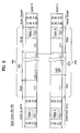
- FIG. 5 illustrates a structure of a dual layer BD-WO according to an embodiment of the present invention.
- the structure of the dual layer BD-WO and designations of each area shown in FIG. 5 are exemplary for description convenience and understanding, and does not limit to the scope of the present invention.
- the BD-WO includes two recording layers.
- the first recording layer (Layer 0 or L0) includes a lead-in area, a data area 40a, and an outer zone area Outer Zone 0.
- the second recording layer (Layer 1 or L1) includes a lead-out area, a data area 40b and an outer zone area Outer Zone 1.
- the lead-in area of the first recording layer (Layer 0) includes a temporary defect management area TDMA 1 and a plurality of final defect management areas DMA1a and DMA 2a.
- the lead-out area of the second recording layer (Layer 1) includes a temporary defect management area TDMA 4, and a plurality of final defect management areas DMA 1b and DMA 2b. Additional final defect management areas (e.g., DMAs 3a, 3b, 4a, 4b) are also provided in the Outer Zone 0 and/or the Outer Zone 1.
- the data area 40a of the first recording layer (Layer 0) includes an inner spare area ISA0, a user data area 42a, and an outer spare area OSA0.
- the data area 40b of the second recording layer (Layer 1) includes an inner spare area ISA1, a user data area 42b, and an outer spare area OSA1.
- the outer spare area OSA0 and/or the outer spare area OSA1 includes a TDMA (e.g., TDMA 2 or TDMA 3).
- the arrows depicted in each of the areas shown in FIG. 5 are examples of a data recording direction.
- each of the DMAs 1a-4b in each recording layer of the dual layer BD-WO has a size of 32 clusters such that a DMA in the first recording layer and a corresponding DMA in the second recording layer constitute one full DMA.
- the DMAs 1a and 1b constitute one DMA
- the DMAs 2a and 2b constitute one DMA
- the DMAs 3a and 3b constitute one DMA
- the DMAs 4a and 4b constitute one DMA.
- same information is recorded in each of the DMAs 1a, 2a, 3a and 4a of the first recording layer.
- Information, which may be different from the information recorded in the DMAs 1a, 2a, 3a, 4a, is recorded in each of the DMAs 1b, 2b, 3b and 4b.
- the TDMA information already stored in the TDMA(s) is now written onto the DMA(s) as DMA information. This process of transferring the TDMA information into the DMA will now be discussed according to the embodiments of the present invention by referring to FIGS. 6A-11 , where dual layer BD-WOs are discussed.
- FIGS. 6A and 6B illustrate a structure of clusters for one DMA of a general dual layer BD-RE (rewritable disc) and are provided to explain further the aspects of the present invention.
- the method of transferring the TDMA information for the BD-WO according to the present invention assures some reciprocity with the rewritable optical disc (BD-RE).
- the BD-RE includes as shown in FIG. 6A , one DMA composed of a DMA part (Clusters 1 -32) from the first recording layer and a DMA part (Clusters 33-64) from the second recording layer, which are accessed according to the tracking direction indicated with the arrow.
- the same DDS information is repeatedly recorded on the Clusters 1 ⁇ 4 of the DMA, and the DFL information is repeatedly recorded on the Clusters 9 ⁇ 64 of the DMA.
- the Clusters 5 ⁇ 8 are not used at all for defect management.
- the present invention as shown in, e.g., FIGS. 7-11 provides a newly defined DMA structure for a dual layer BD-WO based on the DMA structure of the BD-RE of FIGS. 6A and 6B , for assuring reciprocity with the rewritable optical disc (BD-RE).
- BD-RE rewritable optical disc
- FIGS. 7 to 11 several embodiments of the present invention will be discussed wherein, when the latest disc management information is finalized in a TDMA of the BD-WO, a disc finalize command is received, the TDMA(s) is full, etc., it is transferred and recorded on a DMA of the BD-WO.
- the latest TDFL information and the latest TDDS information in a TDMA are transferred to the DMA as DFL information and DDS information, respectively. This transfer process is also called herein as the TDMA information transfer process.
- one DMA shown in each of FIGS. 7 to 10 corresponds to one DMA composed of DMA parts from the first and second recording layers.
- one DMA (Clusters 1 ⁇ 64) shown in each of FIGS. 7-10 is composed of the DMA 2a (Clusters 1-32) in the first recording layer and the DMA 2b (Clusters 33-64) in the second recording layer of the BD-WO shown in FIG. 5 .
- one TDMA shown in each of FIGS. 7-11 corresponds to a TDMA (e.g., TDMA 1, 2, 3 or 4) on the BD-WO shown in FIG. 5 .
- FIG. 7 illustrates a structure of a DMA and a TDMA of a dual layer BD-WO and a method of transferring data from the TDMA to the DMA according to an embodiment of the present invention.
- the latest defect management information (latest TDFL information and latest TDDS information) in the TDMA is transferred to and recorded on a DMA of the BD-WO.
- the TDDS part including the TDFL location information and the recording mode information
- the disc usage management information (Track-Info or SBM) (e.g., as shown in FIGS. 3 and 4 ) are transferred onto the DMA.
- the Clusters 1-8 of the DMA are designated as a DDS section
- the Clusters 9-64 of the DMA are designated as a DFL section. All the clusters of the DMA in the BD-WO are designated for storing management data.
- the disc usage management information (D0) and the TDDS part (T0) for the first recording layer L0 which may be written separately in the TDMA from the disc usage management information (D1) and the TDDS part (T1) for the second recording layer L1, are transferred and written separately and repeatedly into the DMA.
- the D0 and T0 for the first recording layer L0 are repeatedly (four times) recorded on the Clusters 1 to 4 of the DDS section.
- the D1 and T1 for the second recording layer L1 are repeatedly (four times) recorded on the Clusters 5 to 8 of the DDS section in the DMA.
- the DDS section of the DMA includes the latest TDDS part and the latest disc usage management information for the first and second recording layers written in the following order: D0&T0, D0&T0, D0&T0, DO&T0, D1&T1, D1&T1, D1&T1, D1&T1, where D0&T0 or D1&T1 is recorded in one unit size, e.g., one cluster size.
- the T0/T1 written in the DDS section of the DMA may identify the location of the DFLs in the DMA on the BD-WO, and not necessarily the location of the TDFLs in the TDMA on the BD-WO.
- the Clusters 9-64 (DFL section) of the DMA are used to store therein DFL information which corresponds to or is based on the latest TDFL information in the TDMA.
- the same DFL information can be written repeatedly (e.g., up to seven times) in the DFL section of the DMA. Storing the same information repeatedly in the DDS section or the DFL section ensures that the DMA information is not lost (e.g., due to a defect in a portion of the DMA) and is accurately and completely accessed each time it is needed.
- the latest disc usage management information is recorded each on the front part of a first DMA in the lead-in area and/or on the front/rear part of a DMA in the lead-out area (depending on whether the disc is a single layer or multiple layer).
- This allows the disc usage management information to be accessed quickly at the initial loading time of the disc. Further, the data reliability and data preservation can be assured by repetitive recording of same information in different parts of the disc. For instance, if the Clusters 1-32 of the DMA shown in FIG. 7 is assumed to correspond to the DMA 2a shown in FIG. 5 , then the information recorded in the Clusters 1-32 shown in FIG. 7 is repeatedly recorded in each of the other DMAs 1a, 3a and 4a of the first recording layer.
- the Clusters 33-64 of the DMA shown in FIG. 7 is assumed to correspond to the DMA 2b shown in FIG. 5 , then the information recorded in the Clusters 33-64 shown FIG. 7 is repeatedly recorded in each of the other DMAs 1b, 3b and 4b of the second recording layer.
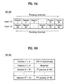
- FIG. 8 illustrates a structure of a DMA and a TDMA of a dual layer BD-WO and a method of transferring data from the TDMA to the DMA according to an embodiment of the present invention.
- This example is identical to the example of FIG. 7 , except that in this example, the latest disc usage management information D0 and the latest TDDS part T0 for the first recording layer L0 is 4-times recorded in the Clusters 1-2 and 5-6 of the DMA, and the latest disc usage management information D1 and the latest TDDS part T1 for the second recording layer L1 is also 4-times recorded in the Clusters 3-4 and 7-8 of the DMA.
- the DDS section of the DMA includes the latest TDDS part and the latest disc usage management information for the first and second recording layers written in the following order: D0&T0, D0&T0, D1&T1, D1&T1, D0&T0, D0&T0, D1&T1, D1&T1, where D0&T0 or D1&T1 is recorded in one unit size, e.g., one cluster size.
- the Clusters 5 to 8 in the DMA can be in a reserved state without any repetitive recording such that only the Clusters 1-4 (and not the Clusters 5-8) have the D0, T0, D1 and T1 recorded thereon.
- FIG. 9 illustrates a structure of a DMA and a TDMA of a dual layer BD-WO and a method of transferring data from the TDMA to the DMA according to an embodiment of the present invention.
- This example is identical to the example of FIG. 7 , except that in this example, each of the (D0&T0) and (D1&T1) for the first and second recording layers L0 and L1 is alternatively and repeatedly recorded in the DDS section of the DMA by the unit of, e.g., one cluster.
- the latest D0 and T0 for the first recording layer L0 is recorded in each of the Clusters 1, 3, 5 and 7 of the DMA
- the latest D1 and T1 for the second recording layer L1 is recorded in each of the Clusters 2, 4, 6 and 8 of the DMA.
- the DDS section of the DMA includes the latest TDDS part and the latest disc usage management information for the first and second recording layers written in the following order: D0&T0, D1&T1, D0&T0, D1&T1, D0&T0, D1&T1, D0&T0, D1&T1, D0&T0, D1&T1, where D0&T0 or D1&T1 is recorded in one unit size, e.g., one cluster size.
- the Clusters 5 to 8 in the DMA can be in a reserved state without any repetitive recording such that only the Clusters 1-4 (and not the Clusters 5-8) have the D0, T0, D1 and T1 recorded thereon.
- FIG. 10 illustrates a structure of a DMA and a TDMA of a dual layer BD-WO and a method of transferring data from the TDMA to the DMA according to an embodiment of the present invention.
- This example is identical to the example of FIG. 7 , except that in this example, the latest D0&T0 and D1&T1 are recorded in the DDS section of the DMA in that order. Then the same information is recorded in the reverse order in the subsequent fields, or the subsequent fields are reserved.
- the latest D0 and T0 for the first recording layer L0 are recorded in each of the Clusters 1, 4, 5 and 8 of the DMA, and the latest D1 and T1 for the second recording layer L1 are recorded in each of the Clusters 2, 3, 6 and 7 of the DMA.
- the DDS section of the DMA includes the latest TDDS part and the latest disc usage management information for the first and second recording layers written in the following order: D0&T0, D1&T1, D1&T1, D0&T0, D0&T0, D1&T1, D1&T1, D0&T0, where D0&T0 or D1&T1 is recorded in one unit size, e.g., one cluster size.
- the Clusters 5 to 8 in the DMA are in a reserved state without any repetitive recording such that only the Clusters 1-4 (and not the Clusters 5-8) have the D0, T0, D1 and T1 recorded thereon in the order of: DO&TO, D1&T1, D1&T1, and DO&T0.
- D0&T0, D1&T1, D1&T1, and D0&T0 prevents all or most of the disc usage management information for one recording layer from being simultaneously destroyed or illegible due to the fact that the recording area of the disc is substantially shaped in circles and a defect such as a scratch on the disc is generated in a linear direction across one or more circles.
- the first and second disc usage management information DO and D1 for the first and second recording layers will be the same.
- the same latest disc usage management information is recorded in the DMA for both the first and second recording layers.
- FIG. 11 illustrates a structure of a DMA and a TDMA of a dual layer BD-WO and a method of transferring data from the TDMA to the DMA according to an embodiment of the present invention.
- This example is identical to the example of FIG. 7 , except that in this example, the latest D0 and T0 for the first recording layer L0 are repeatedly (e.g., four times) recorded in the Clusters 1 to 4 of the DMA, and the latest D1 and T1 for the second recording layer L1 are repeatedly (e.g., four times) recorded in the Clusters 33 to 36 of the DMA.
- the Clusters 1-32 of the DMA are located on the first recording layer L0 (e.g., as the DMA 2a of FIG.
- the Clusters 33-64 of the DMA are located on the second recording layer L1 (e.g., as the DMA 2b of FIG. 5 ).
- the disc usage management information for the first recording layer is distinguished from the disc usage management information for the second recording layer by being recorded in different recording layers.
- the Clusters 5-8 and 37-40 are reserved and the Clusters 9-32 and 41-64 are used to store therein DFL information as discussed above.
- the latest T0 and D0 for the single recording layer are repeatedly recorded in the DDS section of the DMA.
- the latest TDFL information is repeatedly recorded as needed in the DFL section of the DMA.
Abstract
Description
- The present invention relates to a writable-once optical disc and a management information recording method and apparatus, and more particularly, to a method and apparatus for efficiently recording disc usage management information on a writable-once optical disc.
- Optical disc, which is a kind of optical recording media and can record a large amount of data, is widely being used. Today, a kind of innovative high-density digital versatile disc (HD-DVD) such as a blue ray disc (Blu-ray Disc), which can record and store video data of high quality and audio data of high fidelity for a long time, is under development.
- The Blu-ray disc is a next generation optical recording solution that can store a larger amount of data than a conventional DVD. The Blu-ray disc employs a blue-violet laser with the wavelength of 405 nm which is shorter than the wavelength of 650 nm of a red laser used to access a conventional DVD. The Blu-ray disc has generally a thickness of 1.2 mm and a diameter of 12 cm. It includes a light transmission layer whose thickness is 0.1 mm so that the Blu-ray disc can store a larger amount of data than the current DVDs.
- Various standards related to the Blu-ray discs are in development. Among the different types of Blu-ray discs, a Blu-ray Disc Rewritable (BD-RE) and a Blu-ray Disc Write-Once (BD-WO) are being developed.
-
FIG. 1 schematically illustrates a structure of a recording area of a general BD-RE. Referring toFIG. 1 , the BD-RE includes a recording layer divided into a lead-in area, a data area and a lead-out area. The data area includes a user data area for recording user data thereon, and an inner spare area ISAO and an outer spare area OSAO each allocated in the inner tracks and the outer tracks of the disc. These spare areas are used as replacement areas for replacing data in a defective area of the user data area according to linear replacement. - In the BD-RE, if a defective area is found in the user data area during recording, data in the defective area is transferred to and recorded on a spare area using linear replacement. Further, as defect management information for managing the defective area, position information and the like relating to the defective area and the corresponding spare area are recorded on defect management areas (
DMA 1 ∼ DMA 4) in the lead-in area and the lead-out area. Also, since data can be recorded on and erased from any area of the BD-RE repeatedly (since the BD-RE is rewritable), the entire BD-RE can be randomly used irrespective of a specific recording mode. - In contrast, in a writable-once Blu-ray disc (BD-WO), data can be recorded only one time on a specific area of the disc. As a result, the BD-WO has certain limitations pertaining to recording modes and in randomly using the entire area of the disc due to the defect management difficulty.
- Further, in a BD-WO, management of the defective areas is one of the important matters that needs to be addressed, especially for data recording operations. But since the BD-WO is still in the early development stage, there are no schemes, no disc structures, no apparatuses, and no methods on how to manage the defective areas of the BD-WO, which will be needed for the BD-WO to be commercially viable and operationally feasible. Accordingly, for the BD-WO, a unified specification is required that would satisfy the aforementioned advanced requirements. But any proposed specification relating to the current BD-RE cannot be used because it does not address the needs of the BD-WO.
- Accordingly, the present invention is directed to a writable-once optical disc and a management information recording method and apparatus that substantially obviate one or more problems due to limitations and disadvantages of the background art.
- An object of the present invention is to provide a writable-once optical disc and a management information recording method and apparatus for effectively recording and managing disc usage management information therein.
- Additional advantages, objects, and features of the invention will be set forth in part in the description which follows and in part will become apparent to those having ordinary skill in the art upon examination of the following or may be learned from practice of the invention. The objectives and other advantages of the invention may be realized and attained by the structure particularly pointed out in the written description and claims hereof as well as the appended drawings.
- To achieve these objects and other advantages and in accordance with the purpose of the invention, as embodied and broadly described herein, there is provided a method of managing a writable-once optical recording medium, the recording medium including at least one recording layer, the method comprising: providing a user area and a non-user area on the at least one recording layer of the recording medium; providing at least one temporary defect management area in at least one of the user area and the non-user area, the at least one temporary defect management area allocated to store therein temporary defect management information including disc usage management information, the disc usage management information indicating a recording or non-recording status of the user area of the recording medium; and providing at least one final defect management area in the non-user area.
- In accordance with an aspect of the present invention, a method of managing a writable-once optical recording medium, the recording medium including at least one recording layer, the at least one recording layer having at least one temporary defect management area and at least one final defect management area, includes: recording temporary defect management information in the at least one temporary defect management area of the recording medium, the temporary defect management information including disc usage management information indicating a recording use status of the recording medium; and transferring the temporary defect management information from the at least one temporary defect management area to the at least one final defect management area of the recording medium.
- In accordance with an aspect of the present invention, an apparatus for managing a writable-once optical recording medium, the recording medium including at least one recording layer, includes a combination of components configured for: providing a user area and a non-user area on the at least one recording layer of the recording medium; providing at least one temporary defect management area in at least one of the user area and the non-user area, the at least one temporary defect management area allocated to store therein temporary defect management information including disc usage management information, the disc usage management information indicating a recording or non-recording status of the user area of the recording medium; and providing at least one final defect management area in the non-user area.
- In accordance with an aspect of the present invention, an apparatus for managing a writable-once optical recording medium, the recording medium including at least one recording layer, the at least one recording layer having at least one temporary defect management area and at least one final defect management area, the apparatus includes a combination of components configured for: recording temporary defect management information in the at least one temporary defect management area of the recording medium, the temporary defect management information including disc usage management information indicating a recording use status of the recording medium; and transferring the temporary defect management information from the at least one temporary defect management area to the at least one final defect management area of the recording medium.
- In accordance with an aspect of the present invention, a writable-once optical recording medium includes: at least one recording layer including a user area and a non-user area; at least one temporary defect management area provided in at least one of the user area and the non-user area of the recording medium, so as to store therein temporary defect management information including disc usage management information, the disc usage management information indicating a recording or non-recording status of the user area of the recording medium; and at least one final defect management area provided in the non-user area.
- In accordance with an aspect of the present invention, a writable-once optical recording medium includes: at least one recording layer including at least one temporary defect management area and at least one final defect management area, wherein temporary defect management information is recorded in the at least one temporary defect management area of the recording medium, the temporary defect management information including disc usage management information indicating a recording use status of the recording medium, and wherein the temporary defect management information is transferred from the at least one temporary defect management area to the at least one final defect management area of the recording medium.
- It is to be understood that both the foregoing general description and the following detailed description of the present invention are exemplary and explanatory and are intended to provide further explanation of the invention as claimed.
- Further objects and advantages of the invention can be more fully understood from the following detailed description taken in conjunction with the accompanying drawings, in which:
-
FIG. 1 schematically illustrates a structure of a general single-layer BD-RE: -
FIG. 2 is a block diagram of an optical recording/reproducing device according the present invention; -
FIG. 3 illustrates a structure of a writable-once optical disc such as a single layer BD-WO according to an embodiment of the present invention; -
FIG. 4 illustrates an example of a DDS structure on a rewritable disc, a TDDS structure on a BD-WO and a disc management information recording method for the BD-WO according to an embodiment of the present invention; -
FIG. 5 illustrates a structure of a writable-once optical disc such as a dual layer BD-WO according to an embodiment of the present invention; -
FIGS. 6A and 6B illustrate a structure of the clusters in a DMA of a dual layer BD-RE, for explaining further the aspects of the present invention; -
FIG. 7 illustrates a structure of a DMA and a TDMA of a dual layer BD-WO and a method of transferring data from the TDMA to the DMA according to an embodiment of the present invention; -
FIG. 8 illustrates a structure of a DMA and a TDMA of a dual layer BD-WO and a method of transferring data from the TDMA to the DMA according to an embodiment of the present invention; -
FIG. 9 illustrates a structure of a DMA and a TDMA of a dual layer BD-WO and a method of transferring data from the TDMA to the DMA according to an embodiment of the present invention; -
FIG. 10 illustrates a structure of a DMA and a TDMA of a dual layer BD-WO and a method of transferring data from the TDMA to the DMA according to an embodiment of the present invention; -
FIG. 11 illustrates a structure of a DMA and a TDMA of a dual layer BD-WO and a method of transferring data from the TDMA to the DMA according to an embodiment of the present invention; and -
FIG. 12 illustrates a structure of a writable-once optical disc such as a single layer BD-WO according to another embodiment of the present invention. - Reference will now be made in detail to the preferred embodiments of the present invention, examples of which are illustrated in the accompanying drawings. Wherever possible, the same reference numerals will be used throughout the drawings to refer to the same or like parts.
-
FIG. 2 is an example of a block diagram of an optical disc recording/reproducingdevice 20 according to an embodiment of the present invention. The optical disc recording/reproducingdevice 20 includes anoptical pickup 22 for writing/reading data to/from anoptical recording medium 21, aservo unit 23 for controlling thepickup 22 to maintain a distance between an objective lens of thepickup 22 and therecording medium 21 and for tracking relevant tracks on therecording medium 21, adata processor 24 for processing and supplying input data to thepickup 22 for writing, and for processing data read from therecording medium 21, aninterface 25 for exchanging data and/or commands with anyexternal host 30, a memory orstorage 27 for storing information and data therein including defect management data as needed (e.g., temporary defect management information, etc.) associated with therecording medium 21, and a microprocessor orcontroller 26 for controlling the operations and elements of the recording/reproducingdevice 20. Data to be written/read to/from therecording medium 21 may also be stored in thememory 27 if needed. All the components of the recording/reproducingdevice 20 are operatively coupled. Therecording medium 21 is a recording medium of write-once type such as a BD-WO. - All the methods and disc structures discussed herein according to the present invention can be implemented using the recording/reproducing
device 20 ofFIG. 2 or any other suitable device/system. For example, themicrocomputer 26 of thedevice 20 may be used to control allocation of the disc structure and to control the recording of defect management data on the recording medium and the transferring of the defect management data from a temporary area (e.g., TDMA) to a permanent or final area (e.g., DMA) on therecording medium 21. The TDMA and DMA will be discussed later in more detail. - A defect management information recording method for a writable-once optical disc such as a BD-WO according to the preferred embodiments of the present invention will be now described in detail with reference to the accompanying drawings. For a discussion convenience, a writable-once Blu-ray disc (BD-WO) will be exemplified. Herein, two types of a BD-WO - a single layer BD-WO and a dual layer BD-WO - are discussed. The single layer BD-WO has a single recording layer, whereas the dual layer BD-WO has two recording layers.
-
FIG. 3 illustrates a structure of a writable-once optical recording medium such as a single-layer BD-WO according to an embodiment of the present invention. Referring toFIG. 3 , the BD-WO includes a lead-in area, a data area, and a lead-out area allocated on the single recording layer. Each of the lead-in area and the lead-out area includes a plurality of defect management areas (DMA 1 andDMA 2;DMA 3 and DMA 4) for storing therein DMA information for defect management. Each of the DMAs 1-4 has a fixed size, e.g., 32 clusters. Generally, in view of the importance of defect management, the same information is written in each of the DMAs 1-4 so that if one of the DMAs is defective, then a different DMA can be accessed to obtain the defect management information. - It should be noted that in a general BD-RE, since data can be repeatedly recorded on and erased from a DMA (although the size of the DMA is limited), a DMA of large size is not required. However, in a BD-WO according to the present invention, since data cannot be repeatedly recorded on and erased from the DMA, a DMA of large size is required for defect management.
- Still referring to
FIG. 3 , the lead-in area further includes a temporary defect management area (TDMA 1) for temporarily storing defect management information therein. The data area includes an inner spare area ISA0, a user data area, and an outer spare area OSA0. Parts of or the entire ISAO and OSAO are used as replacement areas for defective areas in the user data area according to linear replacement. The outer spare area OSAO includes a temporary defect management area (TDMA 2). The defect management information temporarily stored in theTDMA 1 and/orTDMA 2 is also referred to herein as TDMA information. - In one embodiment, the
TDMA 1 allocated to the lead-in area has a fixed size, whereas theTDMA 2 allocated to the outer spare area OSA0 has a variable size depending upon the size of the spare area(s). For example, if the OSAO has a size of N x 256 clusters where N > 0 (N = integer), then theTDMA 2 has a size of P clusters where P = (N x 256)/4. - In one example, the same information may be written in each of the TDMAs 1 and 2. In another example, the TDMAs 1 and 2 may be sequentially used to sequentially record the TDMA information. Regardless, during replacement writing operations for writing data of a defective area onto a spare area, TDMA information is generated (e.g., under control of the microcomputer 26) and written onto the TDMAs 1 and/or 2. The TDMAs are also updated periodically or as needed. When the BD-WO is ready to be finalized (e.g., data writing operation in the user data area is completed, the TDMA(s) are full, or a finalize command received from a user, etc.), then the TDMA information (latest version) temporarily written in the TDMA(s) is transferred and written onto one or each of the DMAs 1-4.
- The TDMA information written in each of the TDMAs 1 and 2 includes temporary defect list (TDFL) information and temporary disc definition structure (TDDS) information. In one embodiment, the TDFL information includes one or a plurality of TDFLs (
TDFL # 1 ∼ TDFL #n). Each TDFL includes one or a plurality of defect entries identifying defects and corresponding replacement areas on the disc. Each defect entry includes location information pertaining to a defective area of the user data area and the corresponding replacement area. For example, during a data recording operation on the BD-WO, if a defective area is found in the user data area, then data written or to be written in that defective area is written in a part (replacement area) of a spare area (e.g., ISAO or OSA0) according to a linear replacement scheme. Then the information pertaining to the defective area and the replacement area and their relationship is entered as a defect entry in the TDFL. For instance, this information may include a first physical sector number of the defective area on the disc, a first physical sector number of the replacement area (spare area) corresponding to that defective area, and any other data pertaining to the defect for defect management. - In one embodiment, the TDDS information written in each of the TDMAs 1 and 2 includes one or a plurality of TDDSs (
TDDS # 1 ∼ TDDS #n). Each TDDS has a fixed size (e.g., one cluster) and includes location information pertaining to the TDFL(s) so that the location of any TDFL can be quickly identified by accessing the TDDS(s). This location information can be written in a portion ofSector 0 of the one cluster and may include one or more physical sector numbers each indicating a location of a TDFL written on the BD-WO, and any other information pertaining to the TDFL information. Here, a cluster has 32 sectors each sector having 2048 bytes. - Each TDDS also includes recording mode information. The recording mode information identifies a recording mode of the BD-WO and can be written in a portion of
Sector 0 of the one cluster. The location information pertaining to the TDFL(s) and the recording mode information discussed above are also referred to herein as a TDDS part. Here, the TDDS part occupies the entire Sector 0 (or any other designated location area). - Each TDDS further includes disc usage management information, which identifies the status of a recording area of the BD-WO and which can be represented in one of the two forms: track information (Track-Info) and space bitmap information (SBM). This structure of the TDDS will be discussed in more detail later by referring to
FIG. 4 . - As the data recording operation for writing data into the data area progresses, the TDMAs may be updated periodically to reflect any recently discovered defective areas and corresponding replacement areas. After each updating of the TDMA, a TDFL and a corresponding TDDS, which may include all previous TDMA information and the recently generated TDMA information, may be written in the TDMA. In this aspect, the latest TDDS and TDFL written in the TDMA of the BD-WO would include the latest TDMA information. Then when the BD-WO is to be finalized, the latest TDDS and TDFL written on the BD-WO are transferred and written in one or each of the DMAs 1-4 as the final and most-updated defect management information.
-
FIG. 4 illustrates a DDS structure of a rewritable disc, an example of a TDDS structure on a BD-WO and a disc management information recording method for the BD-WO according to an embodiment of the present invention. As shown inFIG. 4 , in the DDS of a general rewritable optical disc, only 60 byte information corresponding to an extremely small portion of 1 cluster is used to store therein the DDS information. The entire remaining part of the DDS is all set to 'zero padding'. - In contrast, in the BD-WO, the entire TDDS area is used to store therein the TDDS information. As shown in
FIGS. 3 and4 , the TDDS part (including the location information and the recording mode information) are written in theentire Sector 0 of the cluster assigned as the TDDS, whereas Sectors 1-31 store therein the disc usage management information (Track-Info or SBM). In another example, the disc usage management information can be recorded on the first 31 sectors (Sectors 0 ∼ 30) in the TDDS, and any remaining disc usage management information can be recorded on the last 32nd sector (Sector 31) in the TDDS along with the TDDS part. - The recording mode information identifies one of a plurality of recording modes employed in the BD-WO according to the present invention. In this example, a value of "0000 0000" may be used to indicate a sequential recoding mode, and a value of "0000 0001" may be used to indicate a random recording mode. Obviously, other examples are possible. Information about the BD-WO according to the present invention can be variously determined depending upon the needs through a process of specification regulation.
- The disc usage management information is varied in dependence upon the disc usage. In the BD-WO, the disc usage management information is required for accurately searching and detecting the start point of an available recording area, and is used to distinguish a recording area from a non-recording area on the disc. In this aspect, the disc usage management information indicates where the available recording area and the recorded area are located within the data area (e.g., user data area).
- As mentioned above, the disc usage management information can be represented as either the track information (Track-Info) or the space bitmap information (SBM). The Track-Info is generally used when the BD-WO is recorded in a sequential recording mode. The SBM is generally used when the BD-WO is recorded in a random recording mode. These recording modes can be determined depending on the recording mode identified in the recording mode information stored in the TDDS.
- In conventional writable-once optical discs, the recording status/mode information is expressed as 'track information' in case of compact disc series, and as 'Rzone', 'Fragment' or 'recording range' in case of DVD series. But in the present invention, the aforementioned various expressions relating to the recording status/mode information are commonly designated as 'Track-Info', and accordingly the Track-Info will be appreciated as having such meaning irrespective of expressions.
- In one example, since the tracks on the BD-WO are sequentially used to record during the sequential recording mode, the Track-Info identifies the start point (location) of the recording area (e.g., user data area) of the BD-WO, and the end point (location) of the last recorded portion of the recording area. This information then indicates the start of the next available portion of the recording area on the BND-WO.
- The bitmap information identifies a start point of an available recordable portion of the recording area on the BD-WO using bit values such as '0' and '1'. For instance, if a particular cluster area of the recording area on the BD-WO has been recorded, then it is indicated by allocating a value of '1' to every minimal recording unit (1 cluster). If a cluster area of the recording area has no recorded data thereon, then that cluster is assigned to a value of '0'. In this manner, if the SBM indicates that a particular cluster has a value of '1' assigned thereto, then it indicates that that cluster has been already used (i.e., it has recorded data thereon). If the SBM indicates that a particular cluster has a value of '0', then it indicates that that cluster has not been used yet (i.e., it has no recorded data thereon). Obviously, the reversal or some other values may be used to indicate the recording/non-recording state of each area unit such as the clusters of the user data area. Thus, the SBM makes it possible to express a recording usage status of the disc even in the random recording mode.
-
FIG. 12 illustrates a structure of a writable-once optical recording medium, such as a single-layer BD-WO, according to another embodiment of the present invention. The BD-WO structure ofFIG. 12 is identical to the BD-WO structure ofFIG. 3 , except that the TDDS part, which includes the location information of the TDFL(s) and the recording mode information, is updated and written after each update state, as shown inFIG. 12 . In this aspect, the disc usage management information (Track-Info or SBM) is stored in Sectors 0-30 of one cluster, and the TDDS part is stored inSector 31 of the one cluster. The TDDS part occupies theentire Sector 31. In another example, the TDDS part may be stored in theentire Sector 0 of one cluster, and the Track-Info or SBM may be stored in Sectors 1-31 of the one cluster. -
FIG. 5 illustrates a structure of a dual layer BD-WO according to an embodiment of the present invention. The structure of the dual layer BD-WO and designations of each area shown inFIG. 5 are exemplary for description convenience and understanding, and does not limit to the scope of the present invention. - Referring to
FIG. 5 , the BD-WO includes two recording layers. The first recording layer (Layer 0 or L0) includes a lead-in area, adata area 40a, and an outer zonearea Outer Zone 0. The second recording layer (Layer 1 or L1) includes a lead-out area, adata area 40b and an outer zonearea Outer Zone 1. The lead-in area of the first recording layer (Layer 0) includes a temporary defectmanagement area TDMA 1 and a plurality of final defect management areas DMA1a and DMA 2a. The lead-out area of the second recording layer (Layer 1) includes a temporary defectmanagement area TDMA 4, and a plurality of final defectmanagement areas DMA 1b andDMA 2b. Additional final defect management areas (e.g., DMAs 3a, 3b, 4a, 4b) are also provided in theOuter Zone 0 and/or theOuter Zone 1. - The
data area 40a of the first recording layer (Layer 0) includes an inner spare area ISA0, auser data area 42a, and an outer spare area OSA0. Thedata area 40b of the second recording layer (Layer 1) includes an inner spare area ISA1, auser data area 42b, and an outer spare area OSA1. The outer spare area OSA0 and/or the outer spare area OSA1 includes a TDMA (e.g.,TDMA 2 or TDMA 3). The arrows depicted in each of the areas shown inFIG. 5 are examples of a data recording direction. - Similar to the single layer BD-WO, the TDMAs 1 and 4 may have a fixed size, whereas the TDMAs 2 and 3 in the spare areas may have a variable size depending upon the size of the spare area(s). For example, if the OSAO/OSA1 has a size of N x 256 clusters where N > 0 (N = integer), then the
TDMA 2/TDMA 3 has a size of P clusters where P = (N x 256)/4. - The use and structure of the DMAs and TDMAs on the single layer BD-WO as discussed above applies equally to the DMAs and TDMAs on the dual layer BD-WO. One difference is that each of the DMAs 1a-4b in each recording layer of the dual layer BD-WO has a size of 32 clusters such that a DMA in the first recording layer and a corresponding DMA in the second recording layer constitute one full DMA. For instance, the
DMAs 1a and 1b constitute one DMA, theDMAs 2a and 2b constitute one DMA, theDMAs DMAs DMAs DMAs DMAs - When the BD-WO is to be finalized (e.g., data writing operation in the user data area is completed, the TDMA(s) are full, or a finalize command received from a user, a host, a disk manufacturer, etc.), the TDMA information already stored in the TDMA(s) is now written onto the DMA(s) as DMA information. This process of transferring the TDMA information into the DMA will now be discussed according to the embodiments of the present invention by referring to
FIGS. 6A-11 , where dual layer BD-WOs are discussed. -
FIGS. 6A and 6B illustrate a structure of clusters for one DMA of a general dual layer BD-RE (rewritable disc) and are provided to explain further the aspects of the present invention. The method of transferring the TDMA information for the BD-WO according to the present invention assures some reciprocity with the rewritable optical disc (BD-RE). - Similar to the DMA structure of the BD-WO, the BD-RE includes as shown in
FIG. 6A , one DMA composed of a DMA part (Clusters 1 -32) from the first recording layer and a DMA part (Clusters 33-64) from the second recording layer, which are accessed according to the tracking direction indicated with the arrow. As shown inFIG. 6B , the same DDS information is repeatedly recorded on theClusters 1 ∼ 4 of the DMA, and the DFL information is repeatedly recorded on the Clusters 9 ∼ 64 of the DMA. However, in the BD-RE, the Clusters 5 ∼ 8 are not used at all for defect management. - The present invention as shown in, e.g.,
FIGS. 7-11 provides a newly defined DMA structure for a dual layer BD-WO based on the DMA structure of the BD-RE ofFIGS. 6A and 6B , for assuring reciprocity with the rewritable optical disc (BD-RE). Referring toFIGS. 7 to 11 , several embodiments of the present invention will be discussed wherein, when the latest disc management information is finalized in a TDMA of the BD-WO, a disc finalize command is received, the TDMA(s) is full, etc., it is transferred and recorded on a DMA of the BD-WO. Particularly, the latest TDFL information and the latest TDDS information in a TDMA are transferred to the DMA as DFL information and DDS information, respectively. This transfer process is also called herein as the TDMA information transfer process. - It should be understood that one DMA shown in each of
FIGS. 7 to 10 corresponds to one DMA composed of DMA parts from the first and second recording layers. For instance, one DMA (Clusters 1 ∼ 64) shown in each ofFIGS. 7-10 is composed of the DMA 2a (Clusters 1-32) in the first recording layer and theDMA 2b (Clusters 33-64) in the second recording layer of the BD-WO shown inFIG. 5 . Also one TDMA shown in each ofFIGS. 7-11 corresponds to a TDMA (e.g.,TDMA FIG. 5 . -
FIG. 7 illustrates a structure of a DMA and a TDMA of a dual layer BD-WO and a method of transferring data from the TDMA to the DMA according to an embodiment of the present invention. - Referring to
FIG. 7 , during the TDMA information transfer process, the latest defect management information (latest TDFL information and latest TDDS information) in the TDMA is transferred to and recorded on a DMA of the BD-WO. Among the TDDS information, the TDDS part (including the TDFL location information and the recording mode information) and the disc usage management information (Track-Info or SBM) (e.g., as shown inFIGS. 3 and4 ) are transferred onto the DMA. In this example, the Clusters 1-8 of the DMA are designated as a DDS section, whereas the Clusters 9-64 of the DMA are designated as a DFL section. All the clusters of the DMA in the BD-WO are designated for storing management data. - More specifically, the disc usage management information (D0) and the TDDS part (T0) for the first recording layer L0, which may be written separately in the TDMA from the disc usage management information (D1) and the TDDS part (T1) for the second recording layer L1, are transferred and written separately and repeatedly into the DMA. In this example, the D0 and T0 for the first recording layer L0 are repeatedly (four times) recorded on the
Clusters 1 to 4 of the DDS section. Further, the D1 and T1 for the second recording layer L1 are repeatedly (four times) recorded on the Clusters 5 to 8 of the DDS section in the DMA. As a result, the DDS section of the DMA includes the latest TDDS part and the latest disc usage management information for the first and second recording layers written in the following order: D0&T0, D0&T0, D0&T0, DO&T0, D1&T1, D1&T1, D1&T1, D1&T1, where D0&T0 or D1&T1 is recorded in one unit size, e.g., one cluster size. In this aspect, in one example, the T0/T1 written in the DDS section of the DMA may identify the location of the DFLs in the DMA on the BD-WO, and not necessarily the location of the TDFLs in the TDMA on the BD-WO. - Moreover, the Clusters 9-64 (DFL section) of the DMA are used to store therein DFL information which corresponds to or is based on the latest TDFL information in the TDMA. In this example, the same DFL information can be written repeatedly (e.g., up to seven times) in the DFL section of the DMA. Storing the same information repeatedly in the DDS section or the DFL section ensures that the DMA information is not lost (e.g., due to a defect in a portion of the DMA) and is accurately and completely accessed each time it is needed.
- In one embodiment, the latest disc usage management information is recorded each on the front part of a first DMA in the lead-in area and/or on the front/rear part of a DMA in the lead-out area (depending on whether the disc is a single layer or multiple layer). This allows the disc usage management information to be accessed quickly at the initial loading time of the disc. Further, the data reliability and data preservation can be assured by repetitive recording of same information in different parts of the disc. For instance, if the Clusters 1-32 of the DMA shown in
FIG. 7 is assumed to correspond to the DMA 2a shown inFIG. 5 , then the information recorded in the Clusters 1-32 shown inFIG. 7 is repeatedly recorded in each of theother DMAs FIG. 7 is assumed to correspond to theDMA 2b shown inFIG. 5 , then the information recorded in the Clusters 33-64 shownFIG. 7 is repeatedly recorded in each of theother DMAs -
FIG. 8 illustrates a structure of a DMA and a TDMA of a dual layer BD-WO and a method of transferring data from the TDMA to the DMA according to an embodiment of the present invention. This example is identical to the example ofFIG. 7 , except that in this example, the latest disc usage management information D0 and the latest TDDS part T0 for the first recording layer L0 is 4-times recorded in the Clusters 1-2 and 5-6 of the DMA, and the latest disc usage management information D1 and the latest TDDS part T1 for the second recording layer L1 is also 4-times recorded in the Clusters 3-4 and 7-8 of the DMA. As a result, the DDS section of the DMA includes the latest TDDS part and the latest disc usage management information for the first and second recording layers written in the following order: D0&T0, D0&T0, D1&T1, D1&T1, D0&T0, D0&T0, D1&T1, D1&T1, where D0&T0 or D1&T1 is recorded in one unit size, e.g., one cluster size. In another variation, the Clusters 5 to 8 in the DMA can be in a reserved state without any repetitive recording such that only the Clusters 1-4 (and not the Clusters 5-8) have the D0, T0, D1 and T1 recorded thereon. -
FIG. 9 illustrates a structure of a DMA and a TDMA of a dual layer BD-WO and a method of transferring data from the TDMA to the DMA according to an embodiment of the present invention. This example is identical to the example ofFIG. 7 , except that in this example, each of the (D0&T0) and (D1&T1) for the first and second recording layers L0 and L1 is alternatively and repeatedly recorded in the DDS section of the DMA by the unit of, e.g., one cluster. - Particularly, as shown in
FIG. 9 , the latest D0 and T0 for the first recording layer L0 is recorded in each of theClusters Clusters -
FIG. 10 illustrates a structure of a DMA and a TDMA of a dual layer BD-WO and a method of transferring data from the TDMA to the DMA according to an embodiment of the present invention. This example is identical to the example ofFIG. 7 , except that in this example, the latest D0&T0 and D1&T1 are recorded in the DDS section of the DMA in that order. Then the same information is recorded in the reverse order in the subsequent fields, or the subsequent fields are reserved. - Particularly, in this example, as shown in
FIG. 10 , the latest D0 and T0 for the first recording layer L0 are recorded in each of theClusters Clusters - The above sequence of D0&T0, D1&T1, D1&T1, and D0&T0 prevents all or most of the disc usage management information for one recording layer from being simultaneously destroyed or illegible due to the fact that the recording area of the disc is substantially shaped in circles and a defect such as a scratch on the disc is generated in a linear direction across one or more circles.
- In the embodiments of
FIGS. 7-10 , if the track information (Track-Info) is used as the disc usage management information for the BD-WO, then the first and second disc usage management information DO and D1 for the first and second recording layers will be the same. As a result, the same latest disc usage management information is recorded in the DMA for both the first and second recording layers. -
FIG. 11 illustrates a structure of a DMA and a TDMA of a dual layer BD-WO and a method of transferring data from the TDMA to the DMA according to an embodiment of the present invention. This example is identical to the example ofFIG. 7 , except that in this example, the latest D0 and T0 for the first recording layer L0 are repeatedly (e.g., four times) recorded in theClusters 1 to 4 of the DMA, and the latest D1 and T1 for the second recording layer L1 are repeatedly (e.g., four times) recorded in theClusters 33 to 36 of the DMA. Here, the Clusters 1-32 of the DMA are located on the first recording layer L0 (e.g., as the DMA 2a ofFIG. 5 ), and the Clusters 33-64 of the DMA are located on the second recording layer L1 (e.g., as theDMA 2b ofFIG. 5 ). As a result, the disc usage management information for the first recording layer is distinguished from the disc usage management information for the second recording layer by being recorded in different recording layers. Also, the Clusters 5-8 and 37-40 are reserved and the Clusters 9-32 and 41-64 are used to store therein DFL information as discussed above. - Although the specific number and order of the repetitions have been identified for recording the D0&T0 and D1&T1 in association with the
FIGS. 7-11 embodiments, the present invention is not limited to such and encompasses any other number and/or different order of the repetitions. - According to the present invention, in a single layer BD-WO case, the latest T0 and D0 for the single recording layer are repeatedly recorded in the DDS section of the DMA. Similarly, the latest TDFL information is repeatedly recorded as needed in the DFL section of the DMA.
- It will be apparent to those skilled in the art that various modifications and variations can be made in the present invention. Thus, it is intended that the present invention covers the modifications and variations of this invention provided they come within the scope of the appended claims and their equivalents.
- The subject matter contained in the following paragraphs that are numbered for allowing reference is part of the disclosure of this document and may be claimed in the present application or in one or plural divisional applications therefrom:
- [1] A method of managing a writable-once optical recording medium, the recording medium including at least one recording layer, the method comprising: providing a user area and a non-user area on the at least one recording layer of the recording medium; providing at least one temporary defect management area in at least one of the user area and the non-user area, the at least one temporary defect management area allocated to store therein temporary defect management information including disc usage management information, the disc usage management information indicating a recording or non-recording status of the user area of the recording medium; and providing at least one final defect management area in the non-user area.
- [2] The method according to paragraph [1], wherein the at least one final defect management area is provided to store therein the disc usage management information transferred from the at least one temporary defect management area.
- [3] The method according to paragraph [2], wherein the at least one recording layer includes a plurality of recording layers each having a final defect management area, and the disc usage management information for each of the recording layers is separately recorded all in at least one of the final defect management areas of the recording layers.
- [4] The method according to paragraph [2], wherein the at least one recording layer includes a plurality of recording layers each having a final defect management area, and the disc usage management information for each of the recording layers is separately and correspondingly recorded in the final defect management area of the corresponding recording layer.
- [5] The method according to paragraph [1], wherein the recording medium is a writable-once Blu-ray disc (BD-WO).
- [6] A method of managing a writable-once optical recording medium, the recording medium including at least one recording layer, the at least one recording layer having at least one temporary defect management area and at least one final defect management area, the method comprising: recording temporary defect management information in the at least one temporary defect management area of the recording medium, the temporary defect management information including disc usage management information indicating a recording use status of the recording medium; and transferring the temporary defect management information from the at least one temporary defect management area to the at least one final defect management area of the recording medium.
- [7] The method according to paragraph [6], wherein the at least one recording layer includes a plurality of recording layers each having a final defect management area, and in the transferring step, the disc usage management information for each of the recording layers is separately recorded all in at least one of the final defect management areas of the recording layers.
- [8] The method of paragraph [7], wherein the disc usage management information includes a first disc usage management information (D0) for a first recording layer of the recording medium and a second disc usage management information (D1) for a second recording layer of the recording medium, such that in the transferring step, the first and second disc usage management information is recorded sequentially in at least one of the final defect management areas of the recording layers according to the following order: D0, D0, D0, D0, D1, D1, D1 and D1.
- [9] The method of paragraph [7], wherein the disc usage management information includes a first disc usage management information (D0) for a first recording layer of the recording medium and a second disc usage management information (D1) for a second recording layer of the recording medium, such that in the transferring step, the first and second disc usage management information is recorded sequentially in at least one of the final defect management areas of the recording layers according to the following order: D0, D0, D1, D1, D0, D0, D1 and D1.
- [10] The method of paragraph [7], wherein the disc usage management information includes a first disc usage management information (D0) for a first recording layer of the recording medium and a second disc usage management information (D1) for a second recording layer of the recording medium, such that in the transferring step, the first and second disc usage management information is recorded sequentially in at least one of the final defect management areas of the recording layers according to the following order: D0, D1, D0, D1, D0, D1, D0 and D1.
- [11] The method of paragraph [7], wherein the disc usage management information includes a first disc usage management information (D0) for a first recording layer of the recording medium and a second disc usage management information (D1) for a second recording layer of the recording medium, such that in the transferring step, the first and second disc usage management information is recorded sequentially in at least one of the final defect management areas of the recording layers according to the following order: D0, D1, D1 and D0.
- [12] The method according to paragraph [11], wherein a certain number of fields, following the recorded first and second disc usage management information, in the at least one of the final defect management areas are reserved for other use.
- [13] The method according to paragraph [6], wherein the at least one recording layer includes a plurality of recording layers each having a final defect management area, and the disc usage management information for each of the recording layers is separately and correspondingly recorded in the final defect management area of the corresponding recording layer.
- [14] The method of paragraph [6], wherein the recording medium includes a recording area on the at least one recording layer, the recording area divided into a plurality of tracks, and the disc usage management information represents track position information identifying an end point of a last recorded track on the recording medium.
- [15] The method of paragraph [6], wherein the disc usage management information represent a space bit map.
- [16] The method according to paragraph [6], wherein the transferring step is performed when the recording medium is to be finalized.
- [17] The method according to paragraph [16], wherein the recording medium is to be finalized if a data recording operation in a user data area of the recording medium is completed, if the at least one temporary defect management area is full, or if a finalize command is received.
- [18] The method according to paragraph [6], wherein in the transferring step, the transferred temporary defect management information further includes temporary defect list information and temporary disc definition structure information, and is latest temporary defect management information written on the recording medium.
- [19] The method according to paragraph [6], wherein the recording medium is a writable-once Blu-ray disc (BD-WO).
- [20] The method according to paragraph [6], wherein in the transferring step, the temporary defect management information transferred is the latest temporary defect management information stored in the at least one temporary defect management area.
- [21] An apparatus for managing a writable-once optical recording medium, the recording medium including at least one recording layer, the apparatus comprising: means for providing a user area and a non-user area on the at least one recording layer of the recording medium; means for providing at least one temporary defect management area in at least one of the user area and the non-user area, the at least one temporary defect management area allocated to store therein temporary defect management information including disc usage management information, the disc usage management information indicating a recording or non-recording status of the user area of the recording medium; and means for providing at least one final defect management area in the non-user area.
- [22] An apparatus for managing a writable-once optical recording medium, the recording medium including at least one recording layer, the at least one recording layer having at least one temporary defect management area and at least one final defect management area, the apparatus comprising: means for recording temporary defect management information in the at least one temporary defect management area of the recording medium, the temporary defect management information including disc usage management information indicating a recording use status of the recording medium; and means for transferring the temporary defect management information from the at least one temporary defect management area to the at least one final defect management area of the recording medium.
- [23] A writable-once optical recording medium comprising: at least one recording layer including a user area and a non-user area; at least one temporary defect management area provided in at least one of the user area and the non-user area of the recording medium, so as to store therein temporary defect management information including disc usage management information, the disc usage management information indicating a recording or non-recording status of the user area of the recording medium; and at least one final defect management area provided in the non-user area.
- [24] The recording medium according to paragraph [23], wherein the at least one final defect management area is provided on the recording medium to store therein the disc usage management information transferred from the at least one temporary defect management area.
- [25] The recording medium according to paragraph [24], wherein the at least one recording layer includes a plurality of recording layers each having a final defect management area, and the disc usage management information for each of the recording layers is separately recorded all in at least one of the final defect management areas of the recording layers.
- [26] The recording medium according to paragraph [24], wherein the at least one recording layer includes a plurality of recording layers each having a final defect management area, and the disc usage management information for each of the recording layers is separately and correspondingly recorded in the final defect management area of the corresponding recording layer.
- [27] The recording medium according to paragraph [23], wherein the recording medium is a writable-once Blu-ray disc (BD-WO).
- [28] A writable-once optical recording medium comprising: at least one recording layer including at least one temporary defect management area and at least one final defect management area, wherein temporary defect management information is recorded in the at least one temporary defect management area of the recording medium, the temporary defect management information including disc usage management information indicating a recording use status of the recording medium, and wherein the temporary defect management information is transferred from the at least one temporary defect management area to the at least one final defect management area of the recording medium.
- [29] The recording medium according to paragraph [28], wherein the at least one recording layer includes a plurality of recording layers each having a final defect management area, and the disc usage management information for each of the recording layers is separately recorded all in at least one of the final defect management areas of the recording layers.
- [30] The recording medium of paragraph [29], wherein the disc usage management information includes a first disc usage management information (D0) for a first recording layer of the recording medium and a second disc usage management information (D1) for a second recording layer of the recording medium, such that the first and second disc usage management information is recorded sequentially in at least one of the final defect management areas of the recording layers according to the following order: D0, D0, D0, D0, D1, D1, D1 and D1.
- [31] The recording medium of paragraph [29], wherein the disc usage management information includes a first disc usage management information (D0) for a first recording layer of the recording medium and a second disc usage management information (D1) for a second recording layer of the recording medium, such that the first and second disc usage management information is recorded sequentially in at least one of the final defect management areas of the recording layers according to the following order: D0, D0, D1, D1, D0, D0, D1 and D1.
- [32] The recording medium of paragraph [29], wherein the disc usage management information includes a first disc usage management information (D0) for a first recording layer of the recording medium and a second disc usage management information (D1) for a second recording layer of the recording medium, such that the first and second disc usage management information is recorded sequentially in at least one of the final defect management areas of the recording layers according to the following order: D0, D1, D0, D1, D0, D1, D0 and D1.
- [33] The recording medium of paragraph [29], wherein the disc usage management information includes a first disc usage management information (D0) for a first recording layer of the recording medium and a second disc usage management information (D1) for a second recording layer of the recording medium, such that the first and second disc usage management information is recorded sequentially in at least one of the final defect management areas of the recording layers according to the following order: D0, D1, D1 and D0.
- [34] The method according to paragraph [33], wherein a certain number of fields, following the recorded first and second disc usage management information, in the at least one of the final defect management areas are reserved for other use.
- [35] The recording medium according to paragraph [28], wherein the at least one recording layer includes a plurality of recording layers each having a final defect management area, and the disc usage management information for each of the recording layers is separately and correspondingly recorded in the final defect management area of the corresponding recording layer.
- [36] The recording medium of paragraph [28], wherein the recording medium includes a recording area on the at least one recording layer, the recording area divided into a plurality of tracks, and the disc usage management information represents track position information identifying an end point of a last recorded track on the recording medium.
- [37] The recording medium of paragraph [28], wherein the disc usage management information represent a space bit map.
- [38] The recording medium according to paragraph [28], wherein the temporary defect management information is transferred from the at least one temporary defect management area to the at least one final defect management area when the recording medium is to be finalized.
- [39] The recording medium according to paragraph [38], wherein the recording medium is to be finalized if a data recording operation in a user data area of the recording medium is completed, if the at least one temporary defect management area is full, or if a finalize command is received.
- [40] The recording medium according to paragraph [28], wherein the transferred temporary defect management information includes temporary defect list information and temporary disc definition structure information, and is latest temporary defect management information written on the recording medium.
- [41] The recording medium according to paragraph [28], wherein the recording medium is a writable-once Blu-ray disc (BD-WO).
- [42] The method according to paragraph [28], wherein the temporary defect management information transferred is the latest temporary defect management information stored in the at least one temporary defect management area.
Claims (17)
- A method of recording management information onto a recording medium, the recording medium including a first recording layer having a first user data area and a second recording layer having a second user data area, the method comprising steps of:(a) recording first disc usage management information onto a temporary defect management area of the recording medium, the first disc usage management information indicating whether or not each recording unit of the first user data area contains data recorded therein;(b) recording second disc usage management information onto the temporary defect management area, the second disc usage management information indicating whether or not each recording unit of the second user data area contains data recorded therein; and(c) recording latest first disc usage management information (D0) and latest second disc usage management information (D1) recorded in the temporary defect management area onto a final defect management area of the recording medium when finalizing the recording medium.
- The method of claim 1, wherein the step of (c) records, in sequence, D0, D1, D1 and D0 onto the final defect management area when finalizing the recording medium.
- The method of claim 1, further comprising:updating the first disc management information or the second disc management information until finalizing the recording medium.
- The method of one of claims 1 to 3, wherein each recording unit of the recording medium is a cluster.
- An apparatus of recording management information onto a recording medium, the recording medium including a first recording layer having a first user data area and a second recording layer having a second user data area, the apparatus comprising:a pickup (22) configured to record data on the recording medium; anda microprocessor (26)configured to control the pickup (22) to record a first disc usage management information onto a temporary defect management area of the recording medium, the first disc usage management information indicating whether or not each recording unit of the first user data area contains data recorded therein;configured to control the pickup (22) to record a second disc usage management information onto the temporary defect management area, the second disc usage management information indicating whether or not each recording unit of the second user data area contains data recorded therein; and configured to control the pickup (22) to record latest first disc usage management information (D0) and latest second disc usage management information (D1) recorded in the temporary defect management area onto a final defect management area of the recording medium when finalizing the recording medium.
- The apparatus of claim 5, wherein the microcomputer (26) is configured to control the pickup (22) to record, in sequence, D0, D1, D1 and D0 onto the final defect management area when finalizing the recording medium.
- The apparatus of claim 5 or 6, wherein the microcomputer (26) is configured to update the first disc management information or the second disc management information until finalizing the recording medium.
- The apparatus of one of claims 5 to 7, wherein each recording unit of the recording medium is a cluster.
- A method of reproducing management information from a recording medium, the recording medium including a first recording layer having a first user data area and a second recording layer having a second user data area, the method comprising a step of:(a) reproducing, from a temporary defect management area of the recording medium, first disc usage management information indicating whether or not each recording unit of the first user data area contains data recorded therein and second disc usage management information indicating whether or not each recording unit of the second user data area contains data recorded therein if the recording medium has not been finalized; and(b) reproducing, form a final defect management area of the recording medium, final first disc usage management information (D0) and final second disc usage management information (D1) if the recording medium has been finalized.
- The method of claim 9, wherein the step of (b) reproduces D0, D1, D1 and D0 recorded when finalizing the recording medium in sequence in the final defect management area.
- The method of claim 9 or 10, wherein each recording unit of the recording medium is a cluster.
- An apparatus of reproducing management information from a recording medium, the recording medium including a first recording layer having a first user data area and a second recording layer having a second user data area, the apparatus comprising:a pickup (22) configured to reproduce data from the recording medium; anda microprocessor (26)configured to control the pickup (22) to reproduce, from a temporary defect management area of the recording medium, first disc usage management information indicating whether or not each recording unit of the first user data area contains data recorded therein and second disc usage management information indicating whether or not each recording unit of the second user data area contains data recorded therein if the recording medium has not been finalized; andconfigured to control the pickup (22) to reproduce, form a final defect management area of the recording medium, final first disc usage management information (D0) and final second disc usage management information (D1) if the recording medium has been finalized.
- The apparatus of claim 12, wherein the microcomputer (26) is configured to control the pickup (22) to reproduce D0, D1, D1 and D0 recorded when finalizing the recording medium in sequence in the final defect management area.
- The apparatus of claim 9 or 10, wherein each recording unit of the recording medium is a cluster.
- A recording medium including a first recording layer having a first user data area and a second recording layer having a second user data area, the recording medium comprising:a temporary defect management area storing first disc usage management information indicating whether or not each recording unit of the first user data area contains data recorded therein and storing second disc usage management information indicating whether or not each recording unit of the second user data area contains data recorded therein until the recording medium is finalized; anda final defect management area storing final first disc usage management information (D0) and final second disc usage management information (D1) when the recording medium is to be finalized.
- The recording medium of claim 15, wherein the final defect management area stores D0, D1, D1 and D0 in sequence when the recording medium is to be finalized.
- The recording medium of claim 15 or 16, wherein each recording unit of the recording medium is a cluster.
Applications Claiming Priority (3)
| Application Number | Priority Date | Filing Date | Title |
|---|---|---|---|
| KR20030011830 | 2003-02-25 | ||
| KR20030016775 | 2003-03-18 | ||
| EP03816086A EP1597722B1 (en) | 2003-02-25 | 2003-09-30 | Write-once optical disc, and method and apparatus for recording management information on write-once optical disc |
Related Parent Applications (2)
| Application Number | Title | Priority Date | Filing Date |
|---|---|---|---|
| EP03816086.7 Division | 2003-09-30 | ||
| EP03816086A Division EP1597722B1 (en) | 2003-02-25 | 2003-09-30 | Write-once optical disc, and method and apparatus for recording management information on write-once optical disc |
Publications (3)
| Publication Number | Publication Date |
|---|---|
| EP2093759A1 true EP2093759A1 (en) | 2009-08-26 |
| EP2093759B1 EP2093759B1 (en) | 2011-07-06 |
| EP2093759B8 EP2093759B8 (en) | 2012-02-08 |
Family
ID=36383845
Family Applications (2)
| Application Number | Title | Priority Date | Filing Date |
|---|---|---|---|
| EP09007491A Expired - Lifetime EP2093759B8 (en) | 2003-02-25 | 2003-09-30 | Write-once optical disk, and method and apparatus for recording and reproducing management information on write-once optical disk |
| EP03816086A Expired - Lifetime EP1597722B1 (en) | 2003-02-25 | 2003-09-30 | Write-once optical disc, and method and apparatus for recording management information on write-once optical disc |
Family Applications After (1)
| Application Number | Title | Priority Date | Filing Date |
|---|---|---|---|
| EP03816086A Expired - Lifetime EP1597722B1 (en) | 2003-02-25 | 2003-09-30 | Write-once optical disc, and method and apparatus for recording management information on write-once optical disc |
Country Status (15)
| Country | Link |
|---|---|
| US (2) | US7188271B2 (en) |
| EP (2) | EP2093759B8 (en) |
| JP (2) | JP4713158B2 (en) |
| KR (1) | KR100949966B1 (en) |
| AT (2) | ATE437433T1 (en) |
| AU (1) | AU2003265099B2 (en) |
| BR (1) | BRPI0318710B1 (en) |
| CA (1) | CA2517112C (en) |
| DE (1) | DE60328531D1 (en) |
| ES (1) | ES2331695T3 (en) |
| HK (1) | HK1089547A1 (en) |
| MX (1) | MXPA05009016A (en) |
| RU (1) | RU2343571C2 (en) |
| TW (1) | TWI298492B (en) |
| WO (1) | WO2004077415A1 (en) |
Families Citing this family (66)
| Publication number | Priority date | Publication date | Assignee | Title |
|---|---|---|---|---|
| US7630283B2 (en) * | 2002-09-26 | 2009-12-08 | Lg Electronics Inc. | Optical disc, method and apparatus for managing a defective area on an optical disc of write once type |
| KR20040027259A (en) * | 2002-09-26 | 2004-04-01 | 엘지전자 주식회사 | Method for managing a defect area on optical disc write once |
| JP2006500723A (en) | 2002-09-26 | 2006-01-05 | エルジー エレクトロニクス インコーポレーテッド | Method for managing defective area on write-once type optical recording medium, and optical recording medium using this method |
| US7233550B2 (en) * | 2002-09-30 | 2007-06-19 | Lg Electronics Inc. | Write-once optical disc, and method and apparatus for recording management information on write-once optical disc |
| KR20040028469A (en) * | 2002-09-30 | 2004-04-03 | 엘지전자 주식회사 | Method for managing a defect area on optical disc write once |
| JP4914610B2 (en) | 2002-12-11 | 2012-04-11 | エルジー エレクトロニクス インコーポレイティド | Overwrite management method and management information recording method for write-once optical disc |
| EP1579443A1 (en) | 2002-12-11 | 2005-09-28 | LG Electronics Inc. | Method and apparatus for managing overwrite on an optical disc write once |
| US7330409B2 (en) * | 2003-01-13 | 2008-02-12 | Samsung Electronics Co., Ltd. | Disc with temporary defect management area, and disc defect management method and apparatus therefor |
| US7372788B2 (en) * | 2003-01-14 | 2008-05-13 | Lg Electronics Inc. | Method for managing defective area on write-once optical recording medium, and optical recording medium using the same |
| TWI314315B (en) * | 2003-01-27 | 2009-09-01 | Lg Electronics Inc | Optical disc of write once type, method, and apparatus for managing defect information on the optical disc |
| US7672204B2 (en) * | 2003-01-27 | 2010-03-02 | Lg Electronics Inc. | Optical disc, method and apparatus for managing a defective area on an optical disc |
| US20040160799A1 (en) * | 2003-02-17 | 2004-08-19 | Park Yong Cheol | Write-once optical disc, and method and apparatus for allocating spare area on write-once optical disc |
| TWI335587B (en) | 2003-02-21 | 2011-01-01 | Lg Electronics Inc | Write-once optical recording medium and defect management information management method thereof |
| US7499383B2 (en) * | 2003-02-21 | 2009-03-03 | Lg Electronics Inc. | Write-once optical disc and method for managing spare area thereof |
| US7675828B2 (en) * | 2003-02-25 | 2010-03-09 | Lg Electronics Inc. | Recording medium having data structure for managing at least a data area of the recording medium and recording and reproducing methods and apparatuses |
| US7477581B2 (en) * | 2003-02-25 | 2009-01-13 | Lg Electronics Inc. | Defect management method for optical recording medium and optical recording medium using the same |
| US7188271B2 (en) * | 2003-02-25 | 2007-03-06 | Lg Electronics Inc. | Write-once optical disc, and method and apparatus for recording management information on write-once optical disc |
| US7385889B2 (en) * | 2003-03-03 | 2008-06-10 | Samsung Electronics Co., Ltd. | Method and apparatus for managing disc defect using temporary DFL and temporary DDS including drive and disc information disc with temporary DFL and temporary DDS |
| AU2003282449A1 (en) * | 2003-03-04 | 2004-09-28 | Lg Electronics Inc. | Method for recording on optical recording medium and apparatus using the same |
| TWI328805B (en) | 2003-03-13 | 2010-08-11 | Lg Electronics Inc | Write-once recording medium and defective area management method and apparatus for write-once recording medium |
| JP3859167B2 (en) * | 2003-03-17 | 2006-12-20 | パイオニア株式会社 | Write-once recording medium, recording apparatus and recording method for write-once recording medium, and playback apparatus and playback method for write-once recording medium |
| WO2004090890A1 (en) | 2003-04-14 | 2004-10-21 | Koninklijke Philips Electronics N.V. | Device for and method of recording information |
| KR100950526B1 (en) * | 2003-04-14 | 2010-03-30 | 삼성전자주식회사 | Method for managing defect considered compatability with rewritable disc, disc drive and a write once disc thereof |
| WO2004100156A1 (en) * | 2003-05-09 | 2004-11-18 | Lg Electronics Inc. | Recording medium having data structure for managing at least a data area of the recording medium and recording and reproducing methods and apparatuses |
| MXPA05012044A (en) * | 2003-05-09 | 2006-02-03 | Lg Electronics Inc | Write once optical disc, and method and apparatus for recovering disc management information from the write once optical disc. |
| JP4846566B2 (en) * | 2003-05-09 | 2011-12-28 | エルジー エレクトロニクス インコーポレイティド | Optical disk that can be recorded only once, and method and apparatus for restoring management information from an optical disk that can be recorded only once |
| JP2007528563A (en) * | 2003-05-09 | 2007-10-11 | エルジー エレクトロニクス インコーポレーテッド | Recording medium having data structure for managing at least data area of recording medium, and recording / reproducing method and apparatus |
| JP4533892B2 (en) * | 2003-07-04 | 2010-09-01 | エルジー エレクトロニクス インコーポレイティド | Method and apparatus for managing overwriting of write-once optical disc |
| RU2355047C2 (en) | 2003-07-14 | 2009-05-10 | Эл Джи Электроникс Инк. | Optical disk for single recording, method and device for recording on it controlling information |
| KR20050009031A (en) * | 2003-07-15 | 2005-01-24 | 엘지전자 주식회사 | Method for recording management information on optical disc write once |
| KR101014703B1 (en) * | 2003-07-15 | 2011-02-21 | 엘지전자 주식회사 | Method and apparatus for managing a defective area on optical disc |
| DK1652174T3 (en) * | 2003-08-05 | 2010-06-07 | Lg Electronics Inc | Disposable optical disc and method and apparatus for recording / reproducing control information on / from the optical disc |
| US7313065B2 (en) * | 2003-08-05 | 2007-12-25 | Lg Electronics Inc. | Write-once optical disc, and method and apparatus for recording/reproducing management information on/from optical disc |
| CA2537889C (en) * | 2003-09-08 | 2013-10-22 | Lg Electronics Inc. | Write-once optical disc, and method and apparatus for recording management information on the write-once optical disc |
| CA2537895A1 (en) * | 2003-09-08 | 2005-03-17 | Lg Electronics Inc. | Write-once optical disc, and method and apparatus for recording management information thereon |
| RU2361295C2 (en) * | 2003-09-08 | 2009-07-10 | ЭлДжи ЭЛЕКТРОНИКС ИНК. | Write-once optical disk and method of recording management data on it |
| KR20050027787A (en) * | 2003-09-16 | 2005-03-21 | 삼성전자주식회사 | Optical disc providing data recording status information |
| KR100964685B1 (en) * | 2003-10-20 | 2010-06-21 | 엘지전자 주식회사 | Method and apparatus for recording and reproducing data on/from optical disc write once |
| JP2005166228A (en) * | 2003-11-10 | 2005-06-23 | Toshiba Corp | Information recording medium, information recording method, information playback method, information recording apparatus, and information playback apparatus |
| TWI263207B (en) * | 2003-12-26 | 2006-10-01 | Ind Tech Res Inst | CD burner disk format determining method |
| JP2007518213A (en) * | 2004-01-05 | 2007-07-05 | サムスン エレクトロニクス カンパニー リミテッド | Optical recording information recording medium, recording / reproducing apparatus, recording / reproducing method, and computer-readable recording medium on which a program for performing the method is recorded |
| RU2401466C2 (en) | 2004-01-30 | 2010-10-10 | Конинклейке Филипс Электроникс Н.В. | Quick access to disk control information |
| JP2005251242A (en) * | 2004-03-01 | 2005-09-15 | Pioneer Electronic Corp | Information recording medium, device and method for recording information thereon, device and method for reproducing information therefrom, computer program for controlling recording/reproducing, and data structure containing control signal |
| KR101113866B1 (en) | 2004-03-19 | 2012-03-02 | 엘지전자 주식회사 | Data structure for a recording medium and method and apparatus of recording data on the recording medium |
| KR101024916B1 (en) * | 2004-03-19 | 2011-03-31 | 엘지전자 주식회사 | Method for writing data in high density optical write once disc and Apparatus for the same |
| CN101017688B (en) * | 2004-03-22 | 2012-08-08 | 日本先锋公司 | Write once type recording medium, recording device, recording method, reproducing device and reproducing method |
| EP1600965A3 (en) | 2004-05-25 | 2006-04-19 | Nec Corporation | Optical disc recording system |
| KR101049117B1 (en) * | 2004-06-08 | 2011-07-14 | 엘지전자 주식회사 | Method and apparatus for recording management information on optical write once disc |
| KR101014727B1 (en) * | 2004-06-23 | 2011-02-16 | 엘지전자 주식회사 | Method and Apparatus for managing a overwrite in Optical write once disc |
| KR101041811B1 (en) | 2004-08-02 | 2011-06-17 | 엘지전자 주식회사 | Method and Apparatus for write / reproducing in Optical storage |
| KR101012378B1 (en) * | 2004-08-16 | 2011-02-09 | 엘지전자 주식회사 | Method and Apparatus for recording / reproducing in Optical storage |
| JP5144265B2 (en) * | 2004-09-14 | 2013-02-13 | エルジー エレクトロニクス インコーポレイティド | Recording medium and recording / reproducing method and apparatus for recording medium |
| US7613874B2 (en) * | 2004-10-14 | 2009-11-03 | Lg Electronics, Inc. | Recording medium, and a method and apparatus for overwriting data in the same |
| JP2006209930A (en) * | 2005-01-31 | 2006-08-10 | Toshiba Corp | Disk drive and disk processing method |
| JP3812584B1 (en) * | 2005-02-16 | 2006-08-23 | 三菱電機株式会社 | Optical disc and optical disc apparatus |
| JP2006294101A (en) * | 2005-04-07 | 2006-10-26 | Ricoh Co Ltd | Information recording/reproducing device |
| KR101227485B1 (en) * | 2005-11-25 | 2013-01-29 | 엘지전자 주식회사 | Recording mdium, Method and Apparatus for recording defect management information on the recording medium |
| KR20070058291A (en) * | 2005-12-02 | 2007-06-08 | 엘지전자 주식회사 | Recording medium, method and apparatus for recording management information on the recording medium |
| JP2008047212A (en) * | 2006-08-15 | 2008-02-28 | Nec Corp | Information recording medium, its recording method, and information recording and reproducing device |
| KR101301649B1 (en) | 2006-11-10 | 2013-08-30 | 삼성전자주식회사 | Recording/reproducing method, recording/reproducing apparatus and information storage medium |
| WO2010004707A1 (en) * | 2008-07-10 | 2010-01-14 | パナソニック株式会社 | Optical disk, optical disk device, optical disk defect registering method, optical disk recording method, and optical disk reproducing method |
| WO2010079572A1 (en) * | 2009-01-06 | 2010-07-15 | パナソニック株式会社 | Write-once information recording medium, information recording apparatus, information recording method, information reproducing apparatus, and information reproducing method |
| WO2010079578A1 (en) * | 2009-01-07 | 2010-07-15 | パナソニック株式会社 | Write-once information recording medium, information recording apparatus, information recording method, information reproducing apparatus, and information reproducing method |
| RU2012111054A (en) | 2009-09-24 | 2013-10-27 | Панасоник Корпорэйшн | NON-RECORDABLE RECORDING MEDIA, METHOD FOR RECORDING INFORMATION, DEVICE FOR RECORDING INFORMATION, METHOD FOR PLAYING INFORMATION, DEVICE FOR PLAYING INFORMATION AND METHOD FOR PREPARING INFORMATION |
| US8406107B2 (en) | 2009-09-25 | 2013-03-26 | Panasonic Corporation | Write-once information recording medium, information recording method, information recording apparatus, information reproducing method, information reproducing apparatus and manufacturing method of the information recording medium |
| DE102015111889B4 (en) * | 2015-07-22 | 2020-02-27 | Andreas Reichhardt | Procedure for testing an agricultural sprayer |
Citations (3)
| Publication number | Priority date | Publication date | Assignee | Title |
|---|---|---|---|---|
| WO1984000628A1 (en) | 1982-07-30 | 1984-02-16 | Western Electric Co | Management of defects in storage media |
| EP0350920A2 (en) | 1988-07-13 | 1990-01-17 | Matsushita Electric Industrial Co., Ltd. | A method of managing defective sectors in a disk-shaped information recording medium and an apparatus for performing the same |
| JP2002245723A (en) | 2001-02-19 | 2002-08-30 | Matsushita Electric Ind Co Ltd | Defect management information reproducing method |
Family Cites Families (126)
| Publication number | Priority date | Publication date | Assignee | Title |
|---|---|---|---|---|
| JPS58194143A (en) | 1982-05-07 | 1983-11-12 | Hitachi Ltd | Recording and reproducing system of data |
| US5247494A (en) | 1984-06-08 | 1993-09-21 | Matsushita Electric Industrial Co. Ltd. | Method for recording and reproducing information on and from an optical disk having a read-only recorded zone and a writable and readable zone using a spot laser light |
| JP2635023B2 (en) | 1985-05-02 | 1997-07-30 | 株式会社日立製作所 | Label writing method for file data |
| FR2591015B1 (en) | 1985-11-29 | 1989-05-12 | Picard Michel | WRITING METHOD WITH UPDATING AND READING INFORMATION ON A NON-ERASABLE MEDIUM ORGANIZED IN AREAS |
| JPH01128266A (en) | 1987-11-13 | 1989-05-19 | Pioneer Electron Corp | Method for controlling drive device for writable disk |
| US4963866A (en) | 1989-03-27 | 1990-10-16 | Digital Recorders, Inc. | Multi channel digital random access recorder-player |
| JPH087981B2 (en) | 1989-08-30 | 1996-01-29 | 日本ビクター株式会社 | Additional type write-once information recording medium and information management method thereof |
| JPH0428061A (en) | 1990-05-24 | 1992-01-30 | Matsushita Electric Ind Co Ltd | Information recording medium and information recording and reproducing device |
| US5319626A (en) | 1990-08-27 | 1994-06-07 | Mitsubishi Electric Corporation | Method for rewriting defect management areas on optical disk according to ECMA standard |
| JP3315711B2 (en) | 1990-09-17 | 2002-08-19 | ヒューレット・パッカード・カンパニー | Write management system and method for magneto-optical disk data storage device |
| JPH04141867A (en) | 1990-10-03 | 1992-05-15 | Canon Inc | File managing method |
| JP2887949B2 (en) | 1991-06-27 | 1999-05-10 | 松下電器産業株式会社 | Information recording / reproducing device, information reproducing device, DMA recording method and DMA verification method |
| US5448728A (en) | 1991-08-08 | 1995-09-05 | Sharp Kabushiki Kaisha | Storage medium control system for controlling a write-once read-many storage medium |
| US5235585A (en) | 1991-09-11 | 1993-08-10 | International Business Machines | Reassigning defective sectors on a disk |
| JP3039099B2 (en) | 1992-02-14 | 2000-05-08 | ソニー株式会社 | Optical disk recording apparatus and method |
| JPH05313980A (en) | 1992-05-07 | 1993-11-26 | Olympus Optical Co Ltd | Information recording method |
| CA2120352C (en) | 1992-07-31 | 2002-10-29 | Hideo Obata | Disk recording method and apparatus for identifying and skipping defective clusters |
| US5473753A (en) | 1992-10-30 | 1995-12-05 | Intel Corporation | Method of managing defects in flash disk memories |
| US5687397A (en) | 1993-02-26 | 1997-11-11 | Sony Corporation | System for expansion of data storage medium to store user data |
| JP3453843B2 (en) | 1993-06-08 | 2003-10-06 | ソニー株式会社 | Disk unit |
| JP3333613B2 (en) | 1993-12-07 | 2002-10-15 | 株式会社日立製作所 | Optical information recording medium, optical information recording / reproducing method, and optical information recording / reproducing apparatus |
| US5495466A (en) | 1994-01-10 | 1996-02-27 | Eastman Kodak Company | Write verification in an optical recording system by sensing mark formation while writing |
| JP3558306B2 (en) | 1994-07-26 | 2004-08-25 | パイオニア株式会社 | Multilayer recording disk and recording / reproducing system using the same |
| JP3232945B2 (en) | 1994-08-22 | 2001-11-26 | セイコーエプソン株式会社 | Preprocessing method and input / output device |
| US5650881A (en) | 1994-11-02 | 1997-07-22 | Texas Instruments Incorporated | Support post architecture for micromechanical devices |
| US5740435A (en) | 1994-10-31 | 1998-04-14 | Sony Corporation | Data management apparatus and method for managing data of variable lengths recorded on a record medium |
| JPH08147110A (en) | 1994-11-18 | 1996-06-07 | Sony Corp | Method and device for data recording medium management and data recording medium |
| JPH08153858A (en) | 1994-11-29 | 1996-06-11 | Nec Corp | Manufacture of semiconductor device |
| JP2915307B2 (en) | 1994-12-19 | 1999-07-05 | 株式会社日立製作所 | Information recording control method for optical disk |
| MY112041A (en) | 1995-04-21 | 2001-03-31 | Matsushita Electric Ind Co Ltd | A method for managing defects in an information recording medium, and a device and information recording medium using said method |
| RU2182722C2 (en) | 1995-11-10 | 2002-05-20 | Сони Корпорейшн | Data processing device and method thereof |
| US5900010A (en) | 1996-03-05 | 1999-05-04 | Sony Corporation | Apparatus for recording magneto-optic disks |
| JPH09259537A (en) | 1996-03-25 | 1997-10-03 | Toshiba Corp | Information record disk having alternate area |
| JPH09259576A (en) | 1996-03-25 | 1997-10-03 | Toshiba Corp | Information recording disk with a plurality of control regions |
| US5805536A (en) | 1996-11-07 | 1998-09-08 | Eastman Kodak Company | Method for bandwidth reduction in writeable optical data storage apparatus |
| JP3050375B2 (en) | 1997-03-12 | 2000-06-12 | インターナショナル・ビジネス・マシーンズ・コーポレイション | Disk drive device and disk drive error recovery method |
| KR100239118B1 (en) * | 1997-05-21 | 2000-01-15 | 구자홍 | Optical disk having variable margin region rate and variably setting method of margin region rate on disk |
| JP3707222B2 (en) | 1997-12-18 | 2005-10-19 | 三菱電機株式会社 | Optical disc, optical disc processing apparatus, and optical disc processing method |
| JPH11242850A (en) * | 1998-02-25 | 1999-09-07 | Hitachi Ltd | Real time data recording system |
| KR100292093B1 (en) * | 1998-03-02 | 2001-06-01 | 구자홍 | Method of generating defected area management data of recorded media and generation device and optical recorded media thereof |
| SG129225A1 (en) | 1998-04-20 | 2007-02-26 | Samsung Electronics Co Ltd | Optical data storage medium |
| JPH11338782A (en) | 1998-05-27 | 1999-12-10 | Oki Electric Ind Co Ltd | Storage device and its defective sector substituting method |
| JP2000040305A (en) | 1998-07-21 | 2000-02-08 | Fujitsu Ltd | Recording medium and storage device |
| US6414923B1 (en) | 1998-08-17 | 2002-07-02 | Lg Electronics Inc. | Recording/reproducing method of optical recording medium |
| KR100459161B1 (en) | 1998-11-20 | 2005-01-15 | 엘지전자 주식회사 | optical recording medium and method for assigning spare area and for managing defect area of optical recording medium |
| US6788631B1 (en) | 1998-09-02 | 2004-09-07 | Lc Electronics Inc. | Optical recording medium having recording capacity information and method for indicating recording capacity |
| AU5449799A (en) | 1998-09-10 | 2000-04-03 | Matsushita Electric Industrial Co., Ltd. | Optical information recording medium, method of manufacture thereof, and method of recording and reproduction |
| JP3243220B2 (en) | 1998-09-14 | 2002-01-07 | 株式会社東芝 | Replacement processing method |
| JP2000099401A (en) | 1998-09-22 | 2000-04-07 | Sony Corp | Recording medium, recording method and recorder |
| US7050701B1 (en) | 1998-09-25 | 2006-05-23 | Matsushita Electric Industrial Co., Ltd. | Information recording medium, information recording/reproducing method, and information recording/reproducing device |
| KR100421845B1 (en) | 1998-09-26 | 2004-04-17 | 엘지전자 주식회사 | optical recording medium and method for managing a defective area |
| KR100677066B1 (en) * | 1998-10-10 | 2007-02-01 | 삼성전자주식회사 | Disc having spare area for defect management and method for allocating spare area |
| MXPA01003953A (en) | 1998-10-22 | 2003-03-10 | Matsushita Electric Ind Co Ltd | Information recording medium, and method and apparatus for managing defect thereof. |
| US6466532B1 (en) | 1998-11-10 | 2002-10-15 | Samsung Electronics Co., Ltd. | Recording medium having spare area for defect management and information on defect management, and method and apparatus of allocating spare area and managing defects |
| US6542450B1 (en) | 1998-11-11 | 2003-04-01 | Lg Electronics Inc. | Method for assigning spare area in optical recording medium |
| KR100451718B1 (en) | 1999-01-13 | 2004-10-08 | 엘지전자 주식회사 | Optical recording medium and method for managing defect area and method for controlling record/playback of it |
| US6842580B1 (en) * | 1999-01-27 | 2005-01-11 | Matsushita Electric Industrial Co., Ltd. | Real-time recording/reproduction on an information recording medium including a defective region |
| MY118342A (en) | 1999-02-01 | 2004-10-30 | Matsushita Electric Ind Co Ltd | Information recording medium, information recording method and information recording/reproducing system |
| JP3206657B2 (en) | 1999-02-05 | 2001-09-10 | 日本電気株式会社 | Replacement processing method and information recording / reproducing device |
| US6160778A (en) | 1999-03-08 | 2000-12-12 | Matsushita Electric Industrial Co., Ltd. | Information recording medium, information recording method, information recording apparatus and information reproducing apparatus |
| US6615363B1 (en) | 1999-03-19 | 2003-09-02 | Hitachi Maxell, Ltd. | Optical disk and method of recording on the same |
| WO2001048753A1 (en) | 1999-12-28 | 2001-07-05 | Mitsubishi Chemical Corporation | Rewritable phase change optical disk partly having rom region and data recording and erasing methods for optical disk |
| KR100544175B1 (en) | 1999-05-08 | 2006-01-23 | 삼성전자주식회사 | Recording medium storing linking type information and method for processing defective area |
| JP5095895B2 (en) * | 1999-09-23 | 2012-12-12 | コーニンクレッカ フィリップス エレクトロニクス エヌ ヴィ | Method for immediately writing or reading a file on a disk-shaped recording medium |
| JP3170499B1 (en) * | 1999-09-30 | 2001-05-28 | 松下電器産業株式会社 | Information recording medium, recording method and reproducing method therefor, system control unit therefor, information recording apparatus and information reproducing apparatus |
| US7340153B2 (en) * | 2000-01-11 | 2008-03-04 | Hitachi, Ltd. | Apparatus and method for recording and reproducing information |
| KR100647368B1 (en) * | 2000-01-26 | 2006-11-17 | 엘지전자 주식회사 | Method for formatting of the optical disc |
| US7072256B2 (en) | 2000-03-08 | 2006-07-04 | Matsushita Electric Industrial Co., Ltd. | Information recording medium, information recording method and information reproduction method |
| JP3915368B2 (en) | 2000-03-31 | 2007-05-16 | 株式会社日立製作所 | Information recording / reproducing apparatus and recording / reproducing method thereof |
| US6804797B2 (en) | 2000-04-08 | 2004-10-12 | Samsung Electronics, Co., Ltd. | Method of verifying defect management area information of disc and test apparatus for performing the same |
| US6714502B2 (en) | 2000-04-08 | 2004-03-30 | Samsung Electronics Co., Ltd | Method of verifying defect management area information of optical disc and apparatus for performing the same |
| EP1280348A4 (en) | 2000-04-21 | 2004-10-06 | Sony Corp | Information processing apparatus and method, program, and recorded medium |
| AU2001275040A1 (en) * | 2000-05-30 | 2001-12-11 | Dataplay, Inc. | Defect management system for write-once storage disk |
| KR100746262B1 (en) | 2000-06-06 | 2007-08-03 | 코닌클리케 필립스 일렉트로닉스 엔.브이. | Method of immediate writing or reading files on a disc like recording medium |
| JP2002042448A (en) | 2000-07-26 | 2002-02-08 | Pioneer Electronic Corp | Device and method for information editing and information recording medium on which editing control program is recorded in computer readable manner |
| WO2002011140A1 (en) | 2000-07-31 | 2002-02-07 | Sony Corporation | Data recording method, data outputting method, and data recording and/or reproducing method |
| JP3898430B2 (en) | 2000-09-18 | 2007-03-28 | 株式会社日立製作所 | Optical recording apparatus and optical disk used therefor |
| US20020099950A1 (en) * | 2001-01-22 | 2002-07-25 | Smith Kenneth K. | Method of maintaining integrity of an instruction or data set |
| JP3971117B2 (en) * | 2001-03-22 | 2007-09-05 | 株式会社東芝 | Information recording medium, information recording apparatus, information recording method, information reproducing apparatus, and information reproducing method |
| JP2002298360A (en) | 2001-03-30 | 2002-10-11 | Canon Inc | Method and device for recording information in information recording medium |
| US7092334B2 (en) | 2001-04-12 | 2006-08-15 | Hitachi-Lg Data Storage Korea, Inc. | Method of detecting a defect area of a disk |
| US6766418B1 (en) | 2001-04-30 | 2004-07-20 | Emc Corporation | Methods and apparatus for accessing data using a cache |
| JP3925144B2 (en) * | 2001-10-12 | 2007-06-06 | 株式会社日立製作所 | Recording method and recording medium |
| JP2003151216A (en) | 2001-11-12 | 2003-05-23 | Hitachi Ltd | Information recording method and information recorder |
| TWI245279B (en) * | 2001-11-20 | 2005-12-11 | Lite On It Corp | Method for dynamically adjusting the writing speed of a CD drive |
| JP4100913B2 (en) | 2002-01-15 | 2008-06-11 | 株式会社リコー | Information reproduction apparatus, data management information acquisition method, data management information acquisition program, storage medium, and reproduction system |
| EP1472685A1 (en) * | 2002-01-18 | 2004-11-03 | Koninklijke Philips Electronics N.V. | Optical data storage medium and use of such medium |
| US7123556B2 (en) | 2002-01-22 | 2006-10-17 | Matsushita Electric Industrial Co., Ltd. | Multi-layered information recording medium with spare defect management areas |
| CN101281769B (en) | 2002-01-22 | 2013-11-06 | 松下电器产业株式会社 | Multi-layer information recording medium, recording apparatus, and recording method |
| JP4078198B2 (en) | 2002-01-31 | 2008-04-23 | 松下電器産業株式会社 | Information recording medium and defect management area position determination method |
| US7027059B2 (en) | 2002-05-30 | 2006-04-11 | Intel Corporation | Dynamically constructed rasterizers |
| JP2004014088A (en) * | 2002-06-11 | 2004-01-15 | Sony Corp | Disk recording medium, recording method and disk drive system |
| JP4279515B2 (en) | 2002-06-25 | 2009-06-17 | 株式会社日立グローバルストレージテクノロジーズ | Recording / playback device |
| TWI248067B (en) * | 2002-07-04 | 2006-01-21 | Mediatek Inc | Method for managing spare blocks of optical disk |
| TWI273575B (en) | 2002-08-03 | 2007-02-11 | Samsung Electronics Co Ltd | Information storage medium and method of recording and/or reproducing with respect to the medium |
| TWI294622B (en) * | 2002-08-12 | 2008-03-11 | Samsung Electronics Co Ltd | Disc with tdds and tdfl, and method and apparatus for managing defect in the same |
| US6826140B2 (en) | 2002-08-26 | 2004-11-30 | Bae Systems Information And Electronic Systems Integration Inc | Multichannel digital recording system with multi-user detection |
| KR100888591B1 (en) * | 2002-09-10 | 2009-03-16 | 삼성전자주식회사 | Method and apparatus for allotting adaptively spare area and disc thereof |
| US7630283B2 (en) * | 2002-09-26 | 2009-12-08 | Lg Electronics Inc. | Optical disc, method and apparatus for managing a defective area on an optical disc of write once type |
| KR20040028469A (en) * | 2002-09-30 | 2004-04-03 | 엘지전자 주식회사 | Method for managing a defect area on optical disc write once |
| US7233550B2 (en) | 2002-09-30 | 2007-06-19 | Lg Electronics Inc. | Write-once optical disc, and method and apparatus for recording management information on write-once optical disc |
| JP2004127471A (en) * | 2002-10-07 | 2004-04-22 | Pioneer Electronic Corp | Recording device and its control method, and reproducing device |
| KR100739673B1 (en) * | 2002-10-10 | 2007-07-13 | 삼성전자주식회사 | Method for managing defect using temporary DFL and temporary DDS |
| KR100667749B1 (en) * | 2002-10-18 | 2007-01-11 | 삼성전자주식회사 | Method and apparatus for managing defect using temporary DFL and temporary DDS, and disc thereof |
| JP4606693B2 (en) * | 2002-11-22 | 2011-01-05 | ソニー株式会社 | Optical disc, recording device, playback device, recording method, playback method |
| JP4914610B2 (en) * | 2002-12-11 | 2012-04-11 | エルジー エレクトロニクス インコーポレイティド | Overwrite management method and management information recording method for write-once optical disc |
| EP1579443A1 (en) * | 2002-12-11 | 2005-09-28 | LG Electronics Inc. | Method and apparatus for managing overwrite on an optical disc write once |
| US7372788B2 (en) * | 2003-01-14 | 2008-05-13 | Lg Electronics Inc. | Method for managing defective area on write-once optical recording medium, and optical recording medium using the same |
| TWI314315B (en) * | 2003-01-27 | 2009-09-01 | Lg Electronics Inc | Optical disc of write once type, method, and apparatus for managing defect information on the optical disc |
| JP4110000B2 (en) * | 2003-01-28 | 2008-07-02 | 株式会社ルネサステクノロジ | Storage device |
| US7188271B2 (en) | 2003-02-25 | 2007-03-06 | Lg Electronics Inc. | Write-once optical disc, and method and apparatus for recording management information on write-once optical disc |
| JP4584915B2 (en) * | 2003-03-08 | 2010-11-24 | サムスン エレクトロニクス カンパニー リミテッド | Write-once recording medium capable of storing data recording state, method for storing data recording state of write-once recording medium, recording medium on which computer-readable code for executing the method is recorded, and data recording and / or reproducing apparatus thereof |
| JP4026517B2 (en) | 2003-03-12 | 2007-12-26 | ソニー株式会社 | Recording medium, recording apparatus, and recording method |
| RU2321080C2 (en) | 2003-03-13 | 2008-03-27 | Самсунг Электроникс Ко. Лтд | One-time recording disk, method for distribution of data area of one-time recordable disk and method for reproducing data from such a disk |
| TWI328805B (en) | 2003-03-13 | 2010-08-11 | Lg Electronics Inc | Write-once recording medium and defective area management method and apparatus for write-once recording medium |
| JP3712726B2 (en) | 2003-03-17 | 2005-11-02 | パイオニア株式会社 | Write-once recording medium, recording apparatus and recording method for write-once recording medium, and playback apparatus and playback method for write-once recording medium |
| KR100739681B1 (en) | 2003-03-24 | 2007-07-13 | 삼성전자주식회사 | Method of overwriting in write-once information storage medium |
| KR100739675B1 (en) | 2003-04-26 | 2007-07-13 | 삼성전자주식회사 | Method of managing defect in recording medium, recording medium drive device and the recording medium therefor |
| CA2531572C (en) * | 2003-07-08 | 2013-01-15 | Matsushita Electric Industrial Co., Ltd. | Write-once recording medium, recording method, recording apparatus, reproduction method, and reproduction apparatus |
| RU2355047C2 (en) * | 2003-07-14 | 2009-05-10 | Эл Джи Электроникс Инк. | Optical disk for single recording, method and device for recording on it controlling information |
| KR20050009031A (en) * | 2003-07-15 | 2005-01-24 | 엘지전자 주식회사 | Method for recording management information on optical disc write once |
| US7313065B2 (en) * | 2003-08-05 | 2007-12-25 | Lg Electronics Inc. | Write-once optical disc, and method and apparatus for recording/reproducing management information on/from optical disc |
| JP4145749B2 (en) * | 2003-08-12 | 2008-09-03 | パイオニア株式会社 | Information recording medium, recording apparatus and recording method for information recording medium, reproducing apparatus and reproducing method for information recording medium, computer program for recording or reproduction control, and data structure including control signal |
| CA2537895A1 (en) * | 2003-09-08 | 2005-03-17 | Lg Electronics Inc. | Write-once optical disc, and method and apparatus for recording management information thereon |
| RU2361295C2 (en) * | 2003-09-08 | 2009-07-10 | ЭлДжи ЭЛЕКТРОНИКС ИНК. | Write-once optical disk and method of recording management data on it |
| CA2537889C (en) * | 2003-09-08 | 2013-10-22 | Lg Electronics Inc. | Write-once optical disc, and method and apparatus for recording management information on the write-once optical disc |
-
2003
- 2003-09-26 US US10/670,335 patent/US7188271B2/en active Active
- 2003-09-30 ES ES03816086T patent/ES2331695T3/en not_active Expired - Lifetime
- 2003-09-30 BR BRPI0318710A patent/BRPI0318710B1/en not_active IP Right Cessation
- 2003-09-30 AT AT03816086T patent/ATE437433T1/en not_active IP Right Cessation
- 2003-09-30 MX MXPA05009016A patent/MXPA05009016A/en active IP Right Grant
- 2003-09-30 EP EP09007491A patent/EP2093759B8/en not_active Expired - Lifetime
- 2003-09-30 CA CA2517112A patent/CA2517112C/en not_active Expired - Fee Related
- 2003-09-30 AU AU2003265099A patent/AU2003265099B2/en not_active Expired
- 2003-09-30 KR KR1020057015767A patent/KR100949966B1/en not_active IP Right Cessation
- 2003-09-30 DE DE60328531T patent/DE60328531D1/en not_active Expired - Lifetime
- 2003-09-30 WO PCT/KR2003/002008 patent/WO2004077415A1/en active Application Filing
- 2003-09-30 RU RU2005126862/28A patent/RU2343571C2/en active
- 2003-09-30 EP EP03816086A patent/EP1597722B1/en not_active Expired - Lifetime
- 2003-09-30 TW TW092127112A patent/TWI298492B/en not_active IP Right Cessation
- 2003-09-30 AT AT09007491T patent/ATE515767T1/en not_active IP Right Cessation
- 2003-09-30 JP JP2004568801A patent/JP4713158B2/en not_active Expired - Fee Related
-
2006
- 2006-10-06 JP JP2006275451A patent/JP4547364B2/en not_active Expired - Fee Related
- 2006-10-11 HK HK06111170A patent/HK1089547A1/en not_active IP Right Cessation
-
2007
- 2007-01-12 US US11/652,691 patent/US7624299B2/en not_active Expired - Fee Related
Patent Citations (3)
| Publication number | Priority date | Publication date | Assignee | Title |
|---|---|---|---|---|
| WO1984000628A1 (en) | 1982-07-30 | 1984-02-16 | Western Electric Co | Management of defects in storage media |
| EP0350920A2 (en) | 1988-07-13 | 1990-01-17 | Matsushita Electric Industrial Co., Ltd. | A method of managing defective sectors in a disk-shaped information recording medium and an apparatus for performing the same |
| JP2002245723A (en) | 2001-02-19 | 2002-08-30 | Matsushita Electric Ind Co Ltd | Defect management information reproducing method |
Also Published As
| Publication number | Publication date |
|---|---|
| JP2006514389A (en) | 2006-04-27 |
| JP4713158B2 (en) | 2011-06-29 |
| MXPA05009016A (en) | 2005-11-23 |
| WO2004077415A1 (en) | 2004-09-10 |
| RU2343571C2 (en) | 2009-01-10 |
| US20070122124A1 (en) | 2007-05-31 |
| ATE515767T1 (en) | 2011-07-15 |
| ATE437433T1 (en) | 2009-08-15 |
| BR0318710A (en) | 2007-03-06 |
| EP2093759B1 (en) | 2011-07-06 |
| JP4547364B2 (en) | 2010-09-22 |
| JP2007042277A (en) | 2007-02-15 |
| DE60328531D1 (en) | 2009-09-03 |
| EP2093759B8 (en) | 2012-02-08 |
| RU2005126862A (en) | 2006-08-10 |
| KR100949966B1 (en) | 2010-03-29 |
| AU2003265099A1 (en) | 2004-09-17 |
| CA2517112A1 (en) | 2004-09-10 |
| US20040193947A1 (en) | 2004-09-30 |
| HK1089547A1 (en) | 2006-12-01 |
| ES2331695T3 (en) | 2010-01-13 |
| CA2517112C (en) | 2012-11-13 |
| EP1597722A1 (en) | 2005-11-23 |
| US7624299B2 (en) | 2009-11-24 |
| BRPI0318710B1 (en) | 2016-05-31 |
| EP1597722B1 (en) | 2009-07-22 |
| US7188271B2 (en) | 2007-03-06 |
| TW200416727A (en) | 2004-09-01 |
| AU2003265099B2 (en) | 2008-04-24 |
| TWI298492B (en) | 2008-07-01 |
| KR20050103957A (en) | 2005-11-01 |
Similar Documents
| Publication | Publication Date | Title |
|---|---|---|
| EP2093759B1 (en) | Write-once optical disk, and method and apparatus for recording and reproducing management information on write-once optical disk | |
| EP2093762B1 (en) | Write-once optical disc, and method and apparatus for recording management information on write-once optical disc | |
| EP1609135B1 (en) | Write-once recording medium and defective area management method and apparatus for write-once recording medium | |
| CA2514120C (en) | Optical disc, method and apparatus for managing a defective area on an optical disc | |
| US20040105363A1 (en) | Disc with temporary disc definition structure (TDDS) and temporary defect list (TDFL), and method of and apparatus for managing defect in the same | |
| CA2534982C (en) | Write-once optical disc, and method and apparatus for recording/reproducing management information on/from optical disc | |
| EP2068322A2 (en) | Write once optical disc, and method and apparatus for recovering disc management information from the write once optical disc | |
| JP2008502093A (en) | Method and apparatus for recording management information on a recording medium, and recording medium |
Legal Events
| Date | Code | Title | Description |
|---|---|---|---|
| PUAI | Public reference made under article 153(3) epc to a published international application that has entered the european phase |
Free format text: ORIGINAL CODE: 0009012 |
|
| 17P | Request for examination filed |
Effective date: 20090605 |
|
| AC | Divisional application: reference to earlier application |
Ref document number: 1597722 Country of ref document: EP Kind code of ref document: P |
|
| AK | Designated contracting states |
Kind code of ref document: A1 Designated state(s): AT BE BG CH CY CZ DE DK EE ES FI FR GB GR HU IE IT LI LU MC NL PT RO SE SI SK TR |
|
| RIN1 | Information on inventor provided before grant (corrected) |
Inventor name: KIM, SUNG DAE Inventor name: PARK, YONG CHEOL |
|
| GRAC | Information related to communication of intention to grant a patent modified |
Free format text: ORIGINAL CODE: EPIDOSCIGR1 |
|
| GRAP | Despatch of communication of intention to grant a patent |
Free format text: ORIGINAL CODE: EPIDOSNIGR1 |
|
| RTI1 | Title (correction) |
Free format text: WRITE-ONCE OPTICAL DISK, AND METHOD AND APPARATUS FOR RECORDING AND REPRODUCING MANAGEMENT INFORMATION ON WRITE-ONCE OPTICAL DISK |
|
| GRAS | Grant fee paid |
Free format text: ORIGINAL CODE: EPIDOSNIGR3 |
|
| RIN1 | Information on inventor provided before grant (corrected) |
Inventor name: KIM, SUNG DAE Inventor name: PARK, YONG CHEOL |
|
| GRAA | (expected) grant |
Free format text: ORIGINAL CODE: 0009210 |
|
| RAP1 | Party data changed (applicant data changed or rights of an application transferred) |
Owner name: LG ELECTRONICS INC. |
|
| AC | Divisional application: reference to earlier application |
Ref document number: 1597722 Country of ref document: EP Kind code of ref document: P |
|
| AK | Designated contracting states |
Kind code of ref document: B1 Designated state(s): AT BE BG CH CY CZ DE DK EE ES FI FR GB GR HU IE IT LI LU MC NL PT RO SE SI SK TR |
|
| REG | Reference to a national code |
Ref country code: GB Ref legal event code: FG4D |
|
| REG | Reference to a national code |
Ref country code: CH Ref legal event code: EP |
|
| REG | Reference to a national code |
Ref country code: IE Ref legal event code: FG4D |
|
| REG | Reference to a national code |
Ref country code: DE Ref legal event code: R096 Ref document number: 60337647 Country of ref document: DE Effective date: 20110901 |
|
| REG | Reference to a national code |
Ref country code: NL Ref legal event code: T3 |
|
| REG | Reference to a national code |
Ref country code: ES Ref legal event code: FG2A Ref document number: 2367756 Country of ref document: ES Kind code of ref document: T3 Effective date: 20111108 |
|
| PG25 | Lapsed in a contracting state [announced via postgrant information from national office to epo] |
Ref country code: SI Free format text: LAPSE BECAUSE OF FAILURE TO SUBMIT A TRANSLATION OF THE DESCRIPTION OR TO PAY THE FEE WITHIN THE PRESCRIBED TIME-LIMIT Effective date: 20110706 |
|
| REG | Reference to a national code |
Ref country code: AT Ref legal event code: MK05 Ref document number: 515767 Country of ref document: AT Kind code of ref document: T Effective date: 20110706 |
|
| PG25 | Lapsed in a contracting state [announced via postgrant information from national office to epo] |
Ref country code: FI Free format text: LAPSE BECAUSE OF FAILURE TO SUBMIT A TRANSLATION OF THE DESCRIPTION OR TO PAY THE FEE WITHIN THE PRESCRIBED TIME-LIMIT Effective date: 20110706 Ref country code: SE Free format text: LAPSE BECAUSE OF FAILURE TO SUBMIT A TRANSLATION OF THE DESCRIPTION OR TO PAY THE FEE WITHIN THE PRESCRIBED TIME-LIMIT Effective date: 20110706 Ref country code: PT Free format text: LAPSE BECAUSE OF FAILURE TO SUBMIT A TRANSLATION OF THE DESCRIPTION OR TO PAY THE FEE WITHIN THE PRESCRIBED TIME-LIMIT Effective date: 20111107 Ref country code: BE Free format text: LAPSE BECAUSE OF FAILURE TO SUBMIT A TRANSLATION OF THE DESCRIPTION OR TO PAY THE FEE WITHIN THE PRESCRIBED TIME-LIMIT Effective date: 20110706 |
|
| PG25 | Lapsed in a contracting state [announced via postgrant information from national office to epo] |
Ref country code: CY Free format text: LAPSE BECAUSE OF FAILURE TO SUBMIT A TRANSLATION OF THE DESCRIPTION OR TO PAY THE FEE WITHIN THE PRESCRIBED TIME-LIMIT Effective date: 20110706 Ref country code: AT Free format text: LAPSE BECAUSE OF FAILURE TO SUBMIT A TRANSLATION OF THE DESCRIPTION OR TO PAY THE FEE WITHIN THE PRESCRIBED TIME-LIMIT Effective date: 20110706 Ref country code: GR Free format text: LAPSE BECAUSE OF FAILURE TO SUBMIT A TRANSLATION OF THE DESCRIPTION OR TO PAY THE FEE WITHIN THE PRESCRIBED TIME-LIMIT Effective date: 20111007 |
|
| PG25 | Lapsed in a contracting state [announced via postgrant information from national office to epo] |
Ref country code: SK Free format text: LAPSE BECAUSE OF FAILURE TO SUBMIT A TRANSLATION OF THE DESCRIPTION OR TO PAY THE FEE WITHIN THE PRESCRIBED TIME-LIMIT Effective date: 20110706 Ref country code: MC Free format text: LAPSE BECAUSE OF NON-PAYMENT OF DUE FEES Effective date: 20110930 Ref country code: CZ Free format text: LAPSE BECAUSE OF FAILURE TO SUBMIT A TRANSLATION OF THE DESCRIPTION OR TO PAY THE FEE WITHIN THE PRESCRIBED TIME-LIMIT Effective date: 20110706 |
|
| REG | Reference to a national code |
Ref country code: CH Ref legal event code: PL |
|
| PLBE | No opposition filed within time limit |
Free format text: ORIGINAL CODE: 0009261 |
|
| STAA | Information on the status of an ep patent application or granted ep patent |
Free format text: STATUS: NO OPPOSITION FILED WITHIN TIME LIMIT |
|
| PG25 | Lapsed in a contracting state [announced via postgrant information from national office to epo] |
Ref country code: RO Free format text: LAPSE BECAUSE OF FAILURE TO SUBMIT A TRANSLATION OF THE DESCRIPTION OR TO PAY THE FEE WITHIN THE PRESCRIBED TIME-LIMIT Effective date: 20110706 Ref country code: EE Free format text: LAPSE BECAUSE OF FAILURE TO SUBMIT A TRANSLATION OF THE DESCRIPTION OR TO PAY THE FEE WITHIN THE PRESCRIBED TIME-LIMIT Effective date: 20110706 |
|
| 26N | No opposition filed |
Effective date: 20120411 |
|
| PG25 | Lapsed in a contracting state [announced via postgrant information from national office to epo] |
Ref country code: DK Free format text: LAPSE BECAUSE OF FAILURE TO SUBMIT A TRANSLATION OF THE DESCRIPTION OR TO PAY THE FEE WITHIN THE PRESCRIBED TIME-LIMIT Effective date: 20110706 |
|
| REG | Reference to a national code |
Ref country code: IE Ref legal event code: MM4A |
|
| PG25 | Lapsed in a contracting state [announced via postgrant information from national office to epo] |
Ref country code: CH Free format text: LAPSE BECAUSE OF NON-PAYMENT OF DUE FEES Effective date: 20110930 Ref country code: IE Free format text: LAPSE BECAUSE OF NON-PAYMENT OF DUE FEES Effective date: 20110930 Ref country code: LI Free format text: LAPSE BECAUSE OF NON-PAYMENT OF DUE FEES Effective date: 20110930 |
|
| REG | Reference to a national code |
Ref country code: DE Ref legal event code: R097 Ref document number: 60337647 Country of ref document: DE Effective date: 20120411 |
|
| PG25 | Lapsed in a contracting state [announced via postgrant information from national office to epo] |
Ref country code: LU Free format text: LAPSE BECAUSE OF NON-PAYMENT OF DUE FEES Effective date: 20110930 |
|
| PG25 | Lapsed in a contracting state [announced via postgrant information from national office to epo] |
Ref country code: BG Free format text: LAPSE BECAUSE OF FAILURE TO SUBMIT A TRANSLATION OF THE DESCRIPTION OR TO PAY THE FEE WITHIN THE PRESCRIBED TIME-LIMIT Effective date: 20111006 |
|
| PG25 | Lapsed in a contracting state [announced via postgrant information from national office to epo] |
Ref country code: TR Free format text: LAPSE BECAUSE OF FAILURE TO SUBMIT A TRANSLATION OF THE DESCRIPTION OR TO PAY THE FEE WITHIN THE PRESCRIBED TIME-LIMIT Effective date: 20110706 |
|
| PG25 | Lapsed in a contracting state [announced via postgrant information from national office to epo] |
Ref country code: HU Free format text: LAPSE BECAUSE OF FAILURE TO SUBMIT A TRANSLATION OF THE DESCRIPTION OR TO PAY THE FEE WITHIN THE PRESCRIBED TIME-LIMIT Effective date: 20110706 |
|
| REG | Reference to a national code |
Ref country code: FR Ref legal event code: PLFP Year of fee payment: 13 |
|
| REG | Reference to a national code |
Ref country code: FR Ref legal event code: PLFP Year of fee payment: 14 |
|
| PGFP | Annual fee paid to national office [announced via postgrant information from national office to epo] |
Ref country code: NL Payment date: 20160802 Year of fee payment: 14 |
|
| PGFP | Annual fee paid to national office [announced via postgrant information from national office to epo] |
Ref country code: IT Payment date: 20160912 Year of fee payment: 14 Ref country code: GB Payment date: 20160802 Year of fee payment: 14 Ref country code: DE Payment date: 20160802 Year of fee payment: 14 |
|
| PGFP | Annual fee paid to national office [announced via postgrant information from national office to epo] |
Ref country code: FR Payment date: 20160805 Year of fee payment: 14 |
|
| PGFP | Annual fee paid to national office [announced via postgrant information from national office to epo] |
Ref country code: ES Payment date: 20160808 Year of fee payment: 14 |
|
| REG | Reference to a national code |
Ref country code: DE Ref legal event code: R119 Ref document number: 60337647 Country of ref document: DE |
|
| REG | Reference to a national code |
Ref country code: NL Ref legal event code: MM Effective date: 20171001 |
|
| GBPC | Gb: european patent ceased through non-payment of renewal fee |
Effective date: 20170930 |
|
| PG25 | Lapsed in a contracting state [announced via postgrant information from national office to epo] |
Ref country code: NL Free format text: LAPSE BECAUSE OF NON-PAYMENT OF DUE FEES Effective date: 20171001 |
|
| REG | Reference to a national code |
Ref country code: FR Ref legal event code: ST Effective date: 20180531 |
|
| PG25 | Lapsed in a contracting state [announced via postgrant information from national office to epo] |
Ref country code: GB Free format text: LAPSE BECAUSE OF NON-PAYMENT OF DUE FEES Effective date: 20170930 Ref country code: DE Free format text: LAPSE BECAUSE OF NON-PAYMENT OF DUE FEES Effective date: 20180404 |
|
| PG25 | Lapsed in a contracting state [announced via postgrant information from national office to epo] |
Ref country code: FR Free format text: LAPSE BECAUSE OF NON-PAYMENT OF DUE FEES Effective date: 20171002 Ref country code: IT Free format text: LAPSE BECAUSE OF NON-PAYMENT OF DUE FEES Effective date: 20170930 |
|
| REG | Reference to a national code |
Ref country code: ES Ref legal event code: FD2A Effective date: 20181017 |
|
| PG25 | Lapsed in a contracting state [announced via postgrant information from national office to epo] |
Ref country code: ES Free format text: LAPSE BECAUSE OF NON-PAYMENT OF DUE FEES Effective date: 20171001 |