EP2093553B1 - Apparatus for optimizing shaker system performance and related control methods - Google Patents
Apparatus for optimizing shaker system performance and related control methods Download PDFInfo
- Publication number
- EP2093553B1 EP2093553B1 EP08075809.7A EP08075809A EP2093553B1 EP 2093553 B1 EP2093553 B1 EP 2093553B1 EP 08075809 A EP08075809 A EP 08075809A EP 2093553 B1 EP2093553 B1 EP 2093553B1
- Authority
- EP
- European Patent Office
- Prior art keywords
- supposed
- operating condition
- coil
- field
- drive
- Prior art date
- Legal status (The legal status is an assumption and is not a legal conclusion. Google has not performed a legal analysis and makes no representation as to the accuracy of the status listed.)
- Active
Links
Images





Classifications
-
- G—PHYSICS
- G01—MEASURING; TESTING
- G01M—TESTING STATIC OR DYNAMIC BALANCE OF MACHINES OR STRUCTURES; TESTING OF STRUCTURES OR APPARATUS, NOT OTHERWISE PROVIDED FOR
- G01M7/00—Vibration-testing of structures; Shock-testing of structures
- G01M7/02—Vibration-testing by means of a shake table
- G01M7/022—Vibration control arrangements, e.g. for generating random vibrations
Definitions
- the present invention relates to apparatus for optimization of the electro-dynamic shaker system operating condition according to the test purpose or situation and related method.
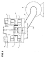
- the inner structure of an electro-dynamic shaker is shown in Figure 1 .
- the field coil 4 is built in the magnetic circuit 2.
- the armature 6 is supported by the air suspension 8 so that it can move along the centre line of the shaker. Specimen of the vibration test can be attached at the head of the armature 6.
- the drive coil 10 is wound at the bottom of the armature 6.
- the air duct 14 is attached at the bottom of the magnetic circuit 2, and the other end of the duct 14 is connected to the blower 16. With rotating the blower 16, air-flow from the air-intake 18 at the top of the magnetic circuit 2 to inside is generated, and this air-flow cools the field coil 4 and the drive coil 10.
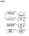
- FIG. 2 A block diagram of a vibration test system using the electro-dynamic shaker in the Figure 1 is shown in Figure 2 .
- Specimen 20 is attached on the top of the armature 6.
- Field current is fed to the field coil 4 by the field power supply 25.
- the blower power supply 27 feeds the power to the blower 16.
- Frequency spectrum of the desired vibration to be applied to the specimen is defined as the control reference spectrum for the vibration controller 22.
- the drive signal from the vibration controller 22 is amplified by the amplifier 24 and fed to the drive coil 10. Yielded vibration is measured by the acceleration sensor 30 attached on the armature 6, and this response signal is returned to the vibration controller 22.
- the spectral analysis of the response signal is carried out by the vibration controller 22, and the spectrum of the drive signal is modified so that the matching of the response spectrum to the reference spectrum will be improved in the next control loop. And the drive waveform signal is generated based on the new drive spectrum, and the drive signal is outputted to the amplifier 24. In such a way, generation of the desired vibration for the specimen to be tested is accomplished.
- Random vibration test random vibration having a required power spectral density is given to the specimen
- Sine vibration test at a fixed frequency Swept-sine vibration test that gives sinusoidal vibration of which frequency varies with time
- SOR Sine-On-Random
- ROR Random-On-Random
- Waveform replication test that regenerates the recorded vibration waveform for testing the specimen just as it was
- the value of the field coil current fed by the field power supply 26 is decided based on the maximum rating force of the corresponding system and fixed at the moment of the shipping at the manufacturer and could not be changed by the operator. So, it was impossible for the operator to carry out a test with reducing the field current value in case of only small excitation force is required to reduce the total power consumption.
- JP-A-200113033 discloses a method to reduce the blower rotation for the purpose of quiet operating when the required force is small. But just the same as above, it intends to solve the heat problem with focusing on the field current only. So, even if the purpose of quiet operating is looked as if it has been solved, the increase of heat generation by the drive current is not solved at all.
- Japanese patent application JP2002206986 discloses a vibration tester which can reduce power consumption.
- This vibration tester has an exciting-force detection means to detect the exciting force and control means which controls the driving electric power of the cooling means.
- said control means controls merely the driving electric power of the cooling means for energy-saving.
- the US patent application US2005120797 also discloses a vibration test equipment which has a plurality of shakers and cooling means using the cooling fluids.
- This equipment is intended to provide high vibratory forces for the size of the shaker and to be suitable for use in adverse environments and in extreme temperature environments (both hot and cold).
- shakers are sealed and thus, it is very important to control the temperature of this equipment for preventing overheating of shaker components, demagnetization of the permanent magnet.
- This invention provides apparatus that can calculate the optimal operating condition of the electro-dynamic shaker system in respect of the criteria such as energy-saving or quiet operating with regard to the performance limitations of the system and with solving the above mentioned problems.
- an operating condition that satisfies the optimization of the focused feature of operation and with satisfying the temperature constraints can be determined by the proposed apparatus.
- the desired operating condition is consistent with the rating of the supply circuit of the drive current.
- tracking control ability to trace the change of the excitation situation and find a new desirable operating condition can be realized. Also, undesirable disturbance in control can be avoided by neglecting smaller changes than the threshold.
- the temperatures of the coils can be cooled down when the supposed temperatures of the field coil and/or drive coil get higher than the result of the calculation means for the supposed temperature.
- the operating condition can be continuously adjusted and controlled to one that is optimized with continuous operation of the test operation.
- test operation based on the optimized operating condition calculated prior to the test operation can be carried out.
- test operation based on the optimized operating condition schedule calculated prior to the test operation can be carried out.
- Steps refer to those shown in Figures 6 and 7 .
- the means configured and adapted to calculate the necessary excitation force is a method to calculate the necessary excitation force substantially based on the drive current.
- the word 'substantially' means not only the case directly based on the drive current data but also such cases to calculate the necessary drive current using the drive current-acceleration characteristics data measured prior to the operation and the data of required acceleration such as a swept-sine profile.
- Step S7 corresponds to the "means configured and adapted to calculate the necessary excitation force" in embodiment.
- Step S82 corresponds to the "means configured and adapted to calculate the supposed drive current" in embodiment.
- Step S84 corresponds to the "means configured and adapted to calculate the supposed temperature" in embodiment.
- Step S88 and S89 correspond to the "means configured and adapted to select the operating condition" in embodiment.
- Step S9 corresponds to the "means configured and adapted to outpu the operating condition” in embodiment.
- "means configured and adapted to output the operating condition” can be one that outputs the operating condition and controls other apparatus, and also can be one that just outputs the operating condition.
- Program means not only executable programs but also includes the concept of source programs, compressed programs and enciphered programs.
- Vibration controller 22 controls the drive signal that is fed to the drive coil 10 via the amplifier 24 so that the vibration having the desired spectrum is fed to the specimen 20.
- the apparatus 100 for optimizing the operating condition observes the drive current fed to the drive coil 10 by the amplifier 24 and the field current outputted by the variable field current power supply 26, and determines a preferable operating condition that meets the purpose of the operation based on this information. And with keeping the situation that the specimen 20 is fed with the desired vibration controlled by the vibration controller 22, the apparatus 100 controls the variable field current power supply 26 and the variable blower power supply 28 so that the operating condition gradually reaches the determined one.
- This embodiment is not only suitable for the random vibration test that feeds vibration having a desired spectrum to the specimen, but also for other vibration test such as swept-sine test that feeds sinusoidal vibration having continuously varying frequency.
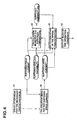
- FIG. 4 A functional block diagram of the apparatus 100 for optimizing the operating condition is shown in Figure 4 .
- the drive current fed to the drive coil 10 is controlled by the vibration controller 22 under the condition that a standard condition field current is fed to the field coil 4.
- the means configured and adapted to calculate the necessary excitation force 34 measures the said field current and the said drive current, and calculates the excitation force that the said shaker 1 is generating.
- the excitation force value calculated as in above is the force necessary to feed the desired vibration to specimen 20 using this shaker 1.
- the means configured and adapted to calculate the supposed necessary drive current 36 calculates the necessary supposed drive current at each supposed field current that is varied from the said standard field current value.
- the means configured and adapted to calculate the supposed temperature 38 calculates the supposed field coil temperature when the said supposed field current is fed to the field coil 4 and the supposed drive coil temperature when the said supposed drive current is fed to the drive coil 10. As the supposed cooling capability is varied, the calculation means for the supposed temperature 38 calculates the above supposed temperatures.
- the means configured and adapted to select the operating condition 40 selects a combination of supposed field current and supposed cooling capability under which the supposed temperatures of the field coil and the drive coil will not exceed the limitation and the focused feature of operation will be satisfied among multiple combinations of supposed field current and supposed cooling capability when applied as the operating condition to the shaker 1. For instance, when the sound noise is the focused feature of operation, the combination of supposed field current and supposed cooling capability that will realize the minimum blower rotation is selected among the combinations that satisfy the temperature criterion. When the power consumption is the focus of operation, the combination of supposed field current and supposed cooling capability is selected that will realize the minimum total power consumption of the system.
- the means configured and adapted to output the operating condition 42 controls the variable field current power supply 26 to change the field current from the present value to the supposed field current value indicated in the said selected operating condition gradually under the situation the specimen 20 is fed with the desired vibration controlled by the vibration controller 22.
- the means configured and adapted to output the operating condition 42 controls the variable blower power supply 28 to change the blower rotation to the supposed rotation value indicated in the said selected operating condition gradually.
- the transition time for each step in the above gradual change should be kept longer than the necessary time for the stable control by the vibration controller 22 that controls the drive current corresponding to the change of the field current.
- the shaker 1 used in this embodiment has the conventional structure as shown in the Figure 1 , but differs only at the point that the temperature sensor 19 is set at the air-intake 18 for the cooling air and the temperature sensor 19A is set at the vent 14 .
- the temperature sensor 19 and 19A By this temperature sensor 19 and 19A, the temperature of the cooling air and the amount of temperature raised by the heat generation of the coils can be measured.
- the sensor 19 is used. But the sensor 19A can be an alternative, or both of them can be used as stated later.
- FIG. 5 An example of the hardware implementation configuration of the apparatus 100 for the operating condition optimization using a PC (personal computer) and the dedicated hardware is shown in Figure 5 .
- CPU 54 supervises the whole system and the user interface with the connected components such as the main memory 55, hard disk 56, keyboard/mouse 58, display 50 and other peripherals. It is convenient to use a PC for this part.
- a dedicated hardware called “master controller” 25 is connected, and the variable field current power supply 26 and the variable blower power supply 28 is connected to the master controller 25.
- the master controller 25 can command the variable field current power supply 26 and the variable blower power supply 28 and control the outputs of these power supplies.
- the master controller 25 is realized as a DSP (digital signal processor) system having memory and I/O ports. In the memory, program codes for the optimization of the operating condition procedure are stored. The control of the field current using the variable field current power supply 26 and of the blower rotation using the variable blower power supply 28 is carried out via the I/O port.
- the output signals of the sensors from the amplifier 24, from the variable field current power supply 26 and from sensor 19 are digitized by the A/D converter under control of the DSP.
- variable field current power supply 26 and the variable blower power supply 28 are dedicated switching converter systems each designed for each required function. These are dedicated systems comprising of the power circuit and the control circuit (DSP). Each system is controlled by the DSP program on the control board and can communicate with the master controller 25 via network (CAN bus is used in this embodiment). Receiving the command from the master controller 25, the DSP in the variable field current power supply 26, or in the variable blower power supply 28, controls and drives the power devices to operate the required switching converter and thereby supply the required output.
- DSP control circuit
- an OS operating system
- dedicated software that supervises the control of the dedicated hardware and user interface are loaded.
- the software works together with the OS to affect the function required.
- the OS can be omitted when possible.
- Data of the characteristics of the shaker 1 and the excitation system are necessary for the apparatus 100 for optimizing the operating condition and to determine the optimal operating condition.
- the characteristic data are recorded in the master controller 25 as the program codes 27 for the optimization.
- Data of Field current - Force coefficient relationship experimental formula, Power consumption formula, Temperature model formula, the standard operating condition and the ratings of the amplifier are recorded in the codes.
- FIG. 6 A flowchart of the optimization program 27 for the operating condition is shown in Figure 6 .
- the operator fixes the specimen 20 on the top part of the armature 6 of the shaker 1 and sets the vibration controller 22 so that the desired vibration will be fed to the specimen 20.
- a desired random vibration is to be fed to the specimen 20.
- the desired vibration is described by frequency spectrum data, and the operator inputs the given spectrum data to the vibration controller 22.
- the CPU 54 of the apparatus 100 inquires the operator to select the criteria of the optimization (For example Energy saving or Quiet noise or other parameter) through the display 50.
- the operator selects the criteria using the keyboard/mouse 58.
- the CPU 54 records the selected criteria of the optimization on the memory 52, and sends the information to the master controller 25.
- the master controller 25 records the received data of the criteria on the memory (step S4).
- the CPU 54 of the apparatus 100 reads the recorded standard operating condition, and commands the variable field current power supply 26 to output the field current of standard value I fon [A] via the I/O port 57 and the master controller 25.
- the variable field current power supply 26 controls the field current to be I fon [A].
- the CPU 54 commands the variable blower power supply 28 to control the blower rotation to be the standard value of V on [Hz] (step S5).
- the operator manipulates the vibration controller 22 to control the shaker 1 to feed the desired vibration to the specimen 20.
- the vibration controller 22 controls the vibration controller 22 to control the shaker 1 to feed the desired vibration to the specimen 20.
- some automatic control of the vibration controller 22 for this activity by the apparatus 100 is possible.
- the response acceleration is monitored by the sensor 30, and according to the acceleration information the drive current from the amplifier 24 is controlled, and the desired vibration is fed to the specimen 20.
- step S6 After the control by the vibration controller 22 is settled, the master controller 25 carries out step S6.
- the vibration control is settled after passing of a definite time (e.g. 1[s]). Judgment of the control settlement can be done when the change of the drive current RMS value has settled within a threshold by monitoring the said drive current.
- step S6 the master controller 25 measures the field current I f0 which is the output of the variable field current power supply 26, and measures the drive current signal which is the output from the amplifier 24 and gets the RMS value I d0 and the peak value I d0_peak . Also, the cooling air temperature T in is measured by the output of the temperature sensor 19.
- step S7 the master controller 25 calculates the excitation force necessary to carry out the required test under the present load condition:
- the master controller 25 searches and determines the optimal operating condition based on the calculated data of necessary force RMS value F 1 and the peak value F 1_peak , referring to the optimization criteria indicated by the CPU 54 (step S8).
- control by the vibration controller 22 is kept and the vibration testing of the specimen is continued.
- the master controller 25 selects the operating condition that meets the optimization criteria among the combinations of the conditions of varied field coil current and the varied blower rotation.
- step S84 calculation of total power consumption and estimate of the temperatures of the drive and field coil are done.
- the drive power consumption P d , the field power consumption P f and the blower power consumption P b are calculated by the following Power consumption formulae:
- P d R d ⁇ 0 ⁇ 1 + c d ⁇ T in - T d ⁇ 0 ⁇ I d 2 / 1 - R d ⁇ 0 ⁇ c d I d 2 ⁇ k d ⁇ V ⁇ d
- P f R f ⁇ 0 ⁇ 1 + c f ⁇ T in - T f ⁇ 0 ⁇ I f 2 / 1 - R f ⁇ 0 ⁇ c f I f 2 ⁇ k f ⁇ V ⁇ f
- P b P b ⁇ 0 ⁇ V / V 0 3
- the total power P t is calculated as the sum of P d , P f and P b .
- the master controller 25 judges whether the estimated value of T f and T d are within the predetermined limitation of coil temperature (step S85).
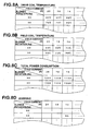
- a marking that indicates the condition is impossible to be used (e.g. "NG") is recorded, in addition to the records of the calculated values of total power P t , estimated temperatures of the field coil T f and of the drive coil T d in the data tables shown in the Figure 8A, B, C and D (step S86).
- Figure 8A is the data table recording the drive coil equilibrium temperature T d estimation for the combinations of field current and blower rotation. It can be seen that T d is estimated as 60 degree Celsius when the field current is 20[A] and the blower rotation is 60[Hz]. When this temperature value is exceeding the limitation, the marking "NG" is recorded in the table in Figure 8D.
- Figure 8B is the similar table for the field coil temperature T f .
- Figure 8C is that for the total power consumption P t
- Figure 8D is the table to record the cases that either or both of the coil temperatures exceed the limitation.
- the master controller 25 checks whether the blower rotation values to be examined still remain (step S87).
- the blower rotation values to be examined still remain (step S87).
- the drive coil temperature, the field coil temperature and the total power consumption are estimated for all the supposed blower rotation values that should be examined.
- the procedure can be broken at the stage when the violation of the temperature limitation by either of the coils occurred. It is obvious that the lower rotation value gives higher temperature estimates than the critical rotation value.
- step S81 the Force coefficient ⁇ when the field current is varied from I fon to I f is calculated using the Field current-Force relationship (A-2).
- the necessary drive current RMS value I d and the peak value I d_peak are calculated by using the data of the necessary force RMS value F 1 and the peak value F 1_peak calculated in step S7 (step S82).
- I d F 1 / ⁇
- I d_peak F 1 _peak / ⁇
- the calculated supposed drive current RMS value I d is checked whether it is within the maximum rating of the amplifier 24.
- the calculated supposed drive current peak value I d_peak is checked whether it is within the maximum peak rating of the amplifier 24 (step S83).
- marking "NG” is recorded in the corresponding part of the table in Figure 8D .
- the next supposed drive current e.g. 16[A]
- Step 83 When not exceeded, the steps following on from Step 83 are processed, and the data of the temperatures of the coils and the total power consumption under the varied blower rotation values one by one are recorded in the table as shown by Figure 8 .
- all the supposed blower rotation values are examined (or broken in mid-flow), returning to step S81 occurs and further examination about the next field current is carried out.
- the master controller 25 carries out the selection of the optimal operating condition, referring to the table in Figure 8 .
- the minimum total power consumption case in Figure 8C is selected among those possible cases that has no "NG” marking in the table in Figure 8D (step S88).
- the master controller 25 controls the variable field current supply 26 and the variable blower power supply 28 to bring the operating condition to the determined optimal conditions with keeping the vibration test by the vibration controller 22 continued and unaffected (step S9).
- the change of the control condition to the determined optimal condition is gradually carried out in a stepwise fashion.
- the master controller 25 controls each step in the change of the field current to be 1) not larger than a defined value (e.g. 1[A]) and 2) not faster than a defined duration (e.g. 1[s]).
- Condition 1) is to avoid too large change per step, and the condition 2) is to avoid undesirable interference of the control with that of the vibration controller 22.
- Blower rotation is also changed gradually avoiding the mechanical and electrical stress that could occur when the change was too fast.
- the master controller 25 sends the resultant data of the optimization to the CPU 54.
- the CPU 54 indicates the data, as shown by example in Figure 9 , on the display as a report of the control status at present.
- Random vibration test is a test method to generate a stationary random vibration having a defined desired spectrum. Therefore it is usual that the drive current does not show a significant change after it has settled. So, although the automatic optimization process of the operating condition is carried out continuously throughout the testing, it is usual that the resultant operating condition also does not show a significant change.
- the drive current in case of a test that feeds a sinusoidal vibration with its frequency varying (Swept-sine vibration test) , the drive current must be varied with time even if the generated acceleration level was constant because of the existence of the response characteristics of the shaker 1 and test load 20. Even in such cases, the method of this invention can be applicable; for instance when the drive current is averaged and peak value measured for the duration of the full single way of the frequency sweep, an optimization for the whole swept frequency band is possible to be done.
- FIG. 10 A flowchart of the optimization program for the operating condition that the case of the excitation situation does not change too fast is shown in Figure 10 .
- Step S50 and S51 are the same as steps S4 to S8 in the first embodiment, and step S52 is equal to the step S9.
- the master controller 25 continues to monitor the drive current periodically (e.g. once per 0.5[s]).
- step S53 judges whether the drive current varied at an extent larger than a defined threshold or not.
- the change is smaller than the threshold, no change of the operating condition is made. This is to avoid the bad influences to change the condition according to too small changes.
- the optimization process step S6 to S8 in Figure 6
- step S54 the control to bring the system to the new operating condition is done.
- control method in this embodiment can be applied not only to the swept-sine test as above, but also to such situations where the specimen characteristics change during the random vibration test or to situations such as the excitation level is changed during the testing.
- control method can also be applied to any other form of vibration testing, including, but not limited to, Sine-on-Random, Random-on-Random, Spot Sine, Shock, Waveform replication, Resonance Dwell and so on.
- calculation process of the supposed drive current does not pay attention to the frequency characteristics of the control objects.
- Frequency characteristics of the excitation system and/or of the desired vibration can be regarded in the process of calculation of the drive current in the optimization of the operating conditions.
- transition to the determined optimal operating condition is controlled to occur with keeping the test excitation
- some trial excitation stage can be set for the optimization.
- real or actual testing can be carried out after stopping the trial excitation and starting the real test with the operating condition already set to the optimized operating conditions
- CPU 54 measures the drive current during the test operation and records the data as a time series.
- calculation of the optimal operating condition at each moment is carried out by using the recorded drive current data at each moment.
- the calculation process is already described above, and this calculation can be done in an off-line manner using external computers.
- this operating condition data is fed to the master controller 25, and the operation based on the optimal operating condition at each moment (calculated prior to the operation) is carried out.
- off-line calculation of the optimal operating condition and estimation of the effectiveness of the apparatus of this invention becomes possible.
- the optimal operating condition is calculated based on the measured drive current. But direct measurement of the drive current is not always required, but 'substantial measurement' of the drive current is also possible; calculated drive current data using the drive current-acceleration characteristics data measured prior to the operation and the data of required acceleration such as swept-sine profile can be usable for the process.
- the thermal equilibrium temperatures of the coils are estimated using the thermal model of the coil temperature based on the information of the cooling air temperature. But temperature information of the field coil 4 can be gotten through the measurement of the field coil current and voltage; when resistance change by the temperature can be detected, then the coil temperature can be estimated by using a pre-determined table or thermal coefficient of the coil resistance. The same method can be applied to the drive coil 10.
- the direct measurement method of coil temperatures ideally should not be employed in the above stated method and the method to estimate the coil temperature solely based on the information of the currents fed to the coils by using the coil thermal model.
- the estimated coil temperatures can only have the meaning of the "temperature at the thermal equilibrium in the stationary state", there remains the possibility that a very different estimated temperature compared to the actual temperature can occur. Also there is a risk of estimation error caused by the limitation of the thermal model.
- the present temperature of the coils can be known by direct measurement, more accurate optimal control can be possible such as the method to adjust the blower rotation by directly comparing the measured coil temperatures with the temperature limitation.
- the temperature of the field coils and drive coils can be got from measurement of the air inlet temperature and air outlet temperature.
- the temperature difference is proportional to the power dissipated in the coils.
- the power dissipation in the coils is known by measurement and by control and the blower speed is also known by control. With these known parameters, the temperature of the coils can be calculated by using the thermal model.
- the calculation method is explained by using the directly measured data of the drive and field current, but the method can of course include the case that the currents are in-directly measured by voltage.
- the selection of the best fit operating condition is done by the master controller 25. But other methods are possible such as the operator selects from among all the possible conditions that satisfy the criteria and are displayed for the operator.
- sound noise level is estimated through the cooling capability (blower rotation). But direct measurement method of sound noise can be applied to the optimization procedure.
- the focused feature of operation can be defined for example as system energy (minimizing system energy), system efficiency (maximizing system efficiency), blower noise (minimizing blower noise) or any other system feature that would be the focus of minimizing or maximizing the particular system parameter.
- the focused feature of operation may also be a combination of features and weighting may or may not be employed for each feature.
- the time from the beginning of the excitation at step S5 to the data acquisition of the currents and others at step S6 is assumed as a pre-determined definite time. But this time can be managed by the operator according to the content of the testing. This time can also be determined through observation of the drive signal.
- a combination of the field current and the cooling capability is selected among the possible combinations of supposed field current and supposed blower rotation that satisfy the temperature condition searched by varying both of the field current and the blower rotation.
- This method is suitable for the waveform replication test such as those called SHOCK test during which the field current should be kept fixed or for the idling state during which the field current can be kept constant at a smaller value.
- operating condition is determined by the following procedure: Fixing the specimen to be tested to the armature, feeding the determined field current, the drive current is controlled so that the desired vibration is applied to the specimen, and the drive current value in this state is detected. Next, supposed temperatures of the field coil and the drive coil are calculated under each of the supposed cooling capability of the cooling apparatus which is varied for calculation. And a supposed operating condition (blower rotation) that does not exceed the temperature limit is selected as the operating condition. As such, a proper blower rotation can be selected.
- IMV vibration test system model "i240/SA3M” was used as the shaker1 and the amplifier 24, and IMV Digital vibration control system "K2" as the vibration controller 22 was used.
- Specimen 20 was a dummy mass load of 120kg, and the dedicated hardware developed for the embodiment of this method was used. Optimization criterion was "Energy save”.
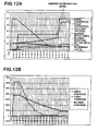
- Figure 11A the reference acceleration profile (desired vibration) was suddenly increased or decreased, and the changes of the drive and field current are seen in the same figure.
- Figure 11B is showing the power consumption at the drive coil 10, consumption at the field coil 4 and consumption at the blower. The dramatic reduction of the blower power consumption and that of the field coil are observed clearly, and these are contributing to reduce the total power consumption.
- Figures 12A and 12B are zoomed displays of the first 80[s] of Figures 11A and 11B and show greater detail.
Landscapes
- Physics & Mathematics (AREA)
- General Physics & Mathematics (AREA)
- Reciprocating, Oscillating Or Vibrating Motors (AREA)
- Apparatuses For Generation Of Mechanical Vibrations (AREA)
- Testing Of Devices, Machine Parts, Or Other Structures Thereof (AREA)
Description
- The present invention relates to apparatus for optimization of the electro-dynamic shaker system operating condition according to the test purpose or situation and related method.
- The inner structure of an electro-dynamic shaker is shown in
Figure 1 . Thefield coil 4 is built in themagnetic circuit 2. Thearmature 6 is supported by the air suspension 8 so that it can move along the centre line of the shaker. Specimen of the vibration test can be attached at the head of thearmature 6. Thedrive coil 10 is wound at the bottom of thearmature 6. - When DC current is fed to the
field coil 4, a static magnetic field is generated at thegap 12. Thedrive coil 10 is set in thisgap 12, and AC current fed to thedrive coil 10 yields a vibratory movement of thearmature 6, and this motion is fed to the specimen attached on thearmature 6 as the vibration for testing. - The
air duct 14 is attached at the bottom of themagnetic circuit 2, and the other end of theduct 14 is connected to theblower 16. With rotating theblower 16, air-flow from the air-intake 18 at the top of themagnetic circuit 2 to inside is generated, and this air-flow cools thefield coil 4 and thedrive coil 10. - Although an air-cooled system is used for explanation here, this invention can be applied also to water-cooled systems by focusing attention to the power consumption or noise generation of the cooling apparatus.
- A block diagram of a vibration test system using the electro-dynamic shaker in the
Figure 1 is shown inFigure 2 .Specimen 20 is attached on the top of thearmature 6. Field current is fed to thefield coil 4 by thefield power supply 25. Theblower power supply 27 feeds the power to theblower 16. Frequency spectrum of the desired vibration to be applied to the specimen is defined as the control reference spectrum for thevibration controller 22. The drive signal from thevibration controller 22 is amplified by theamplifier 24 and fed to thedrive coil 10. Yielded vibration is measured by theacceleration sensor 30 attached on thearmature 6, and this response signal is returned to thevibration controller 22. The spectral analysis of the response signal is carried out by thevibration controller 22, and the spectrum of the drive signal is modified so that the matching of the response spectrum to the reference spectrum will be improved in the next control loop. And the drive waveform signal is generated based on the new drive spectrum, and the drive signal is outputted to theamplifier 24. In such a way, generation of the desired vibration for the specimen to be tested is accomplished. - In addition to the above explained case of Random vibration test ( random vibration having a required power spectral density is given to the specimen ), Sine vibration test at a fixed frequency, Swept-sine vibration test that gives sinusoidal vibration of which frequency varies with time, and SOR (Sine-On-Random) or ROR (Random-On-Random) tests that are based on a combination of the former tests, Shock test that gives a pulse-shaped acceleration change described as a short time waveform, or Waveform replication test that regenerates the recorded vibration waveform for testing the specimen just as it was, are popularly conducted using the electro-dynamic shaker systems.
- In the conventional electro-dynamic shaker systems, the value of the field coil current fed by the
field power supply 26 is decided based on the maximum rating force of the corresponding system and fixed at the moment of the shipping at the manufacturer and could not be changed by the operator. So, it was impossible for the operator to carry out a test with reducing the field current value in case of only small excitation force is required to reduce the total power consumption. - Even when it was allowed for the operator to change the field current by himself by some means, it was not easy to use appropriately, because professional knowledge and skill were required to predict the influence of the change of the field current setting correctly.
- For instance, when the field current is reduced, then the drive current must be increased to keep the excitation force constant. So, reduction of the field current does not directly mean the reduction of total power consumption. A good balance between the field current and the drive current must be taken to achieve energy-saving.
- In the Japanese laid-open patent application
JP-A-200113033 - In addition, the Japanese laid-open patent application
JP-A-200113033 - Further, the Japanese patent application
JP2002206986 - The US patent application
US2005120797 also discloses a vibration test equipment which has a plurality of shakers and cooling means using the cooling fluids. This equipment is intended to provide high vibratory forces for the size of the shaker and to be suitable for use in adverse environments and in extreme temperature environments (both hot and cold). In this equipment shakers are sealed and thus, it is very important to control the temperature of this equipment for preventing overheating of shaker components, demagnetization of the permanent magnet. - This invention provides apparatus that can calculate the optimal operating condition of the electro-dynamic shaker system in respect of the criteria such as energy-saving or quiet operating with regard to the performance limitations of the system and with solving the above mentioned problems.
-
- (1) According to the first aspect of the present invention, an apparatus (100) for determining the operating condition of a shaker system that has a vibration controller (22) for controlling a drive coil (10) via an amplifier (24) and by monitoring an acceleration sensor (30), a variable field current power supply (26) for controlling a field coil (4), a variable blower power supply (28) for controlling a cooling apparatus (16), the drive coil (10) that is set in the static magnetic field generated by the field coil (4) and is driven by electromagnetic force, an armature (6) that transfers the force generated at the drive coil (10) to the test specimen (20), the cooling apparatus (16) being set to cool the field coil (4) and the drive coil (10), is characterized in that it also comprises:
- at leat one temperature sensor at the intake (18) of cooling air of the shaker system;
- means (34) configured and adapted to calculate the necessary excitation force that is the excitation force presently generated by the shaker system, based on information of drive current of the drive coil (10) and from the filed coil (4)
- necessary to yield the desired vibration for the test specimen (20) under condition that a standard field current is fed to the field coil (4);
- means (36) configured and adapted to calculate supposed drive current of the drive coil (10) necessary to generate the necessary excitation force under each supposed field current of the fild coil (4), the supposed field current being supposed to be varied from said standard field current;
- means (38) configured and adapted to calculate supposed temperatures of the field coil (4) to which each of the supposed field current is fed and supposed temperatures of the drive coil (10) to which each of the supposed drive current is fed under each supposed cooling capability of the cooling apparatus (16);
- means (40) configured and adapted to select at least one operating condition that is a combination of the supposed field current and the supposed cooling capability under which the supposed temperatures of the field coil (4) and the drive coil (10) will not exceed limitation and a focused operating feature will be satisfied among multiple combinations of the supposed field current and the supposed cooling capability, the focused operating condition being the minimization or the maximization of a particular system parameter, such as system energy, system efficiency or blower noise;
- means (42) configured and adapted to output at least one of the operating conditions.
- Therefore, an operating condition that satisfies the optimization of the focused feature of operation and with satisfying the temperature constraints can be determined by the proposed apparatus.
- (2) In an apparatus (100) for determining the operating condition according to the second aspect of the present invention, the means (36) configured and adapted to calculate the supposed drive current of the drive coil (10) calculates averaged RMS value and peak value of the supposed drive current; and the means (40) configured and adapted to select the operating condition are capable of using selection criterion that the averaged RMS value and the peak value of the supposed drive current will not exceed the rating RMS value and peak value of the supply circuit of the drive current.
- Therefore, the desired operating condition is consistent with the rating of the supply circuit of the drive current.
- (3) In an apparatus for determining the operating condition according to the third aspect of the present invention, the means (40) configured and adapted to select the operating condition are capable of using selection criteria that the supposed temperatures of the field coil (4) and the drive coil (10) will not exceed temperature limitation, and the sum of the supposed field power consumed by the supposed field current and supposed drive power consumed by the supposed drive current and supposed cooling power to get the supposed cooling capability will be a minimum.
- Therefore, an operating condition to minimize the total power consumption of the shaker system can be set.
- (4) In an apparatus (100) for determining the operating condition according to the fourth aspect of the present invention, the means (40) configured and adapted to select the operating condition are capable of using the selection criteria that the supposed temperatures of the field coil (4) and the drive coil (10) will not exceed temperature limitation, and the cooling apparatus sound noise will be a minimum.
- Therefore, an operating condition to minimize the cooling apparatus noise of the shaker system can be set.
- (5) In an apparatus (100) for determining the operating condition according to the fifth aspect of the present invention, the means (42) configured and adapted to output the operating condition varies the field current gradually in stages from the present value to the supposed value specified in the selected operating condition, and keeps the stepwise change speed slower than the control speed of the vibration controller (22) that controls the drive current so that desired vibration is maintained under the given field current.
- Therefore, it is possible to bring the system operating condition to the determined new condition with keeping the vibration testing to the specimen continued and unaffected.
- (6) An apparatus (100) for determining the operating condition according to the sixth aspect of the present invention, comprises means configured and adapted to monitor the drive current after the means (42) configured and adapted to output the operating condition outputted the selected operating condition, and configured and adapted to obtain a new operating condition by activating the means (34) configured and adapted to calculating the necessary drive force, the means (36) configured and adapted to calculate the supposed drive current, the means (38) configured and adapted to calculate the supposed temperatures and the means configured and adapted to calculate the operating condition, and wherein the new operating condition is outputted from the means (42)configured and adapted to output the operating condition.
- Therefore, tracking control ability to trace the change of the excitation situation and find a new desirable operating condition can be realized. Also, undesirable disturbance in control can be avoided by neglecting smaller changes than the threshold.
- (7) According to the seventh aspect of the present invention, an apparatus (100) for determining the operating condition of a shaker system that has a vibration controller (22) for controlling a drive coil (10) via an amplifier (24) and by monitoring an acceleration sensor (30), a variable field current power supply (26) for controlling a field coil (4), a variable blower power supply (28) for controlling a cooling apparatus (16), the drive coil (10) that is set in static magnetic field generated by the field coil (4) and is driven by electromagnetic force, an armature (6) that transfers force generated at the drive coil (10) to test specimen (20), the cooling apparatus being set to cool the field coil (4) and the drive coil (10), is characterized in that it also comprises:
- at least one temperature sensor at the intake (18) of cooling air of the shaker system;
- means configured and adapted to detect the drive current of the drive coil (10) necessary to yield the desired vibration for the test specimen (20) under the condition of the presently fed field current;
- means (38) configured and adapted to calculate supposed temperatures of the field coil (4) to which each of the present field currents is fed and supposed temperatures of the drive coil (10) to which each of the necessary drive currents is fed under each supposed cooling capability of the cooling apparatus (16);
- means (40) configured and adapted to select at least one operating condition that is a supposed cooling capability under which supposed temperatures of the field coil (4) and the drive coil (10) will not exceed limitation,
- and a focused operating feature will be satisfied among multiple combinations of the supposed field current and the supposed cooling capability, the focused operating condition being the minimization or the maximization of a particular system parameter, such as system energy, system efficiency or blower noise;
- means (42) configured and adapted to output the operating condition.
- Therefore, an operating condition that satisfies the temperature constraints can be determined by the proposed apparatus.
- (8) An apparatus (100) for determining the operating condition according to the eighth aspect of the present invention comprises means configured and adapted to control cooling apparatus that monitors temperatures of the field coil (4) and the drive coil (10) under the controlled operating condition, and controls to increase the cooling capability when either of the temperatures exceeds the limitation.
- Therefore, the temperatures of the coils can be cooled down when the supposed temperatures of the field coil and/or drive coil get higher than the result of the calculation means for the supposed temperature.
- (9) In an apparatus (100) for determining the operating condition according to the ninth aspect of the present invention, the means (42) configured and adapted to output the operating condition outputs the operating condition selected by the means (40) configured and adapted to select the operating condition in a real-time manner.
- Therefore, the operating condition can be continuously adjusted and controlled to one that is optimized with continuous operation of the test operation.
- (10) In an apparatus for determining the operating condition according to the tenth aspect of the present invention, the means (42) configured and adapted to output the operating condition outputs the operating condition selected by the means (40) configured and adapted to select the operating condition prior to the operation.
- Therefore, test operation based on the optimized operating condition calculated prior to the test operation can be carried out.
- (11) In an apparatus (100) for determining the operating condition according to the eleventh aspect of the present invention, the means (40) configured and adapted to select the operating condition calculates the operating condition at each moment as a time series.
- Therefore, test operation based on the optimized operating condition schedule calculated prior to the test operation can be carried out.
- (12) According to the twelfth aspect of the present invention, a method for determining the operating condition of a shaker system that has a vibration controller (22) for controlling a drive coil (10) via an amplifier (24) and by monitoring an acceleration sensor (30), a variable field current power supply (26) for controlling a field coil (4), a variable blower power supply (28) for controlling a cooling apparatus (16), the drive coil (10) that is set in a static magnetic field generated by the field coil (4) and is driven by electromagnetic force, an armature (6) that transfers force generated at the drive coil (10) to the test specimen (20), the cooling apparatus (16) being set to cool the field coil (4) and the drive coil (10), comprises steps of:
- calculating the necessary excitation force that is the excitation force presently generated by the shaker system, based on information of drive current of the drive coil (10) and from the field coil (4) necessary to yield the desired vibration for the test specimen (20) under the condition that a standard field current is fed to the field coil (4);
- calculating the supposed drive current of the drive coil (10) necessary to generate the necessary excitation force under each supposed field current of the field coil (4), the supposed field current being supposed to be varied from said standard field current;
- calculating supposed temperatures of the field coil (4) to which each of the supposed field current is fed and supposed temperatures of the drive coil (10) to which each of the supposed drive current is fed under each supposed cooling capability of the cooling apparatus (16);
- selecting at least one operating condition that is a combination of the supposed field current and the supposed cooling capability under which the supposed temperatures of the field coil and the drive coil will not exceed the limitation and a focused operating feature will be satisfied among multiple combinations of the supposed field current and the supposed cooling capability, the focused operating condition being the minimization or the maximization of a particular system parameter, such as system energy, system efficiency or blower noise; and
- outputting at least one of the operating conditions.
- The following Steps refer to those shown in
Figures 6 and7 . - The means configured and adapted to calculate the necessary excitation force is a method to calculate the necessary excitation force substantially based on the drive current. Here, the word 'substantially' means not only the case directly based on the drive current data but also such cases to calculate the necessary drive current using the drive current-acceleration characteristics data measured prior to the operation and the data of required acceleration such as a swept-sine profile.
- Step S7 corresponds to the "means configured and adapted to calculate the necessary excitation force" in embodiment.
- Step S82 corresponds to the "means configured and adapted to calculate the supposed drive current" in embodiment.
- Step S84 corresponds to the "means configured and adapted to calculate the supposed temperature" in embodiment.
- Step S88 and S89 correspond to the "means configured and adapted to select the operating condition" in embodiment.
- Step S9 corresponds to the "means configured and adapted to outpu the operating condition" in embodiment. "means configured and adapted to output the operating condition" can be one that outputs the operating condition and controls other apparatus, and also can be one that just outputs the operating condition.
- "Program" means not only executable programs but also includes the concept of source programs, compressed programs and enciphered programs.
- The forgoing forms and other forms, objects, and aspects as well as features and advantages of the present invention will become further apparent from the following detailed description of the presently preferred embodiments, read in conjunction with the accompanying drawings. The detailed description and drawings are merely illustrative of the present invention rather than limiting the scope of the present invention being defined by the appended claims and equivalents thereof.
-
-
Figure 1 shows the inner structure of electro-dynamic shaker (air-cooled type). -
Figure 2 is a diagrammatical model of a conventional vibration test system. -
Figure 3 is a diagrammatical model of an embodiment of a vibration test system by this invention. -
Figure 4 is a functional block diagram of the first mode of embodiment of the apparatus for optimizing the operating condition. -
Figure 5 is an example of hardware implementation of the apparatus for optimizing the operating condition. -
Figure 6 is a flowchart of the optimization program of the operatingcondition 27. -
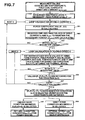
Figure 7 is a flowchart of the optimization program of the operatingcondition 27. -
Figure 8 is a conceptual explanation of a recorded table of combination of the operating conditions. -
Figure 9 is an exemplified display of optimization result. -
Figure 10 is a flowchart of the optimization program of the operatingcondition 27 of the second mode of embodiment. -
Figure 11 is a graphical display of experimental results gotten by the apparatus for optimizing the operating condition in the second mode of embodiment. -
Figure 12 is a graphical display of experimental results gotten by the apparatus for optimizing the operating condition in the second mode of embodiment. - System configuration of the
apparatus 100 for optimizing the operating condition is shown inFigure 3 . Vibration controller 22 (e.g. "K2" of IMV Corporation can be used for this purpose) controls the drive signal that is fed to thedrive coil 10 via theamplifier 24 so that the vibration having the desired spectrum is fed to thespecimen 20. - The
apparatus 100 for optimizing the operating condition observes the drive current fed to thedrive coil 10 by theamplifier 24 and the field current outputted by the variable fieldcurrent power supply 26, and determines a preferable operating condition that meets the purpose of the operation based on this information. And with keeping the situation that thespecimen 20 is fed with the desired vibration controlled by thevibration controller 22, theapparatus 100 controls the variable fieldcurrent power supply 26 and the variableblower power supply 28 so that the operating condition gradually reaches the determined one. - This embodiment is not only suitable for the random vibration test that feeds vibration having a desired spectrum to the specimen, but also for other vibration test such as swept-sine test that feeds sinusoidal vibration having continuously varying frequency.
- A functional block diagram of the
apparatus 100 for optimizing the operating condition is shown inFigure 4 . The drive current fed to thedrive coil 10 is controlled by thevibration controller 22 under the condition that a standard condition field current is fed to thefield coil 4. When the control by the vibration controller 22 -is settled, the means configured and adapted to calculate thenecessary excitation force 34 measures the said field current and the said drive current, and calculates the excitation force that the saidshaker 1 is generating. The excitation force value calculated as in above is the force necessary to feed the desired vibration tospecimen 20 using thisshaker 1. - The means configured and adapted to calculate the supposed necessary drive current 36 calculates the necessary supposed drive current at each supposed field current that is varied from the said standard field current value.
- The means configured and adapted to calculate the supposed
temperature 38 calculates the supposed field coil temperature when the said supposed field current is fed to thefield coil 4 and the supposed drive coil temperature when the said supposed drive current is fed to thedrive coil 10. As the supposed cooling capability is varied, the calculation means for the supposedtemperature 38 calculates the above supposed temperatures. - The means configured and adapted to select the
operating condition 40 selects a combination of supposed field current and supposed cooling capability under which the supposed temperatures of the field coil and the drive coil will not exceed the limitation and the focused feature of operation will be satisfied among multiple combinations of supposed field current and supposed cooling capability when applied as the operating condition to theshaker 1. For instance, when the sound noise is the focused feature of operation, the combination of supposed field current and supposed cooling capability that will realize the minimum blower rotation is selected among the combinations that satisfy the temperature criterion. When the power consumption is the focus of operation, the combination of supposed field current and supposed cooling capability is selected that will realize the minimum total power consumption of the system. - The means configured and adapted to output the operating
condition 42 controls the variable fieldcurrent power supply 26 to change the field current from the present value to the supposed field current value indicated in the said selected operating condition gradually under the situation thespecimen 20 is fed with the desired vibration controlled by thevibration controller 22. At the same time, the means configured and adapted to output the operatingcondition 42 controls the variableblower power supply 28 to change the blower rotation to the supposed rotation value indicated in the said selected operating condition gradually. The transition time for each step in the above gradual change should be kept longer than the necessary time for the stable control by thevibration controller 22 that controls the drive current corresponding to the change of the field current. - As explained above, it is possible to control the operation of the vibration test system to be carried out under a preferable operating condition without disturbing the testing of the
specimen 20. - The
shaker 1 used in this embodiment has the conventional structure as shown in theFigure 1 , but differs only at the point that thetemperature sensor 19 is set at the air-intake 18 for the cooling air and thetemperature sensor 19A is set at thevent 14 . By thistemperature sensor sensor 19 is used. But thesensor 19A can be an alternative, or both of them can be used as stated later. - An example of the hardware implementation configuration of the
apparatus 100 for the operating condition optimization using a PC (personal computer) and the dedicated hardware is shown inFigure 5 .CPU 54 supervises the whole system and the user interface with the connected components such as the main memory 55,hard disk 56, keyboard/mouse 58,display 50 and other peripherals. It is convenient to use a PC for this part. - Via the I/
O port 57, a dedicated hardware called "master controller" 25 is connected, and the variable fieldcurrent power supply 26 and the variableblower power supply 28 is connected to themaster controller 25. Themaster controller 25 can command the variable fieldcurrent power supply 26 and the variableblower power supply 28 and control the outputs of these power supplies. - To measure the drive current from the
amplifier 24, the field current from the variable fieldcurrent power supply 26 and the temperature at thesensor 19, analogue output signals from the sensors are fed to themaster controller 25. Themaster controller 25 is realized as a DSP (digital signal processor) system having memory and I/O ports. In the memory, program codes for the optimization of the operating condition procedure are stored. The control of the field current using the variable fieldcurrent power supply 26 and of the blower rotation using the variableblower power supply 28 is carried out via the I/O port. The output signals of the sensors from theamplifier 24, from the variable fieldcurrent power supply 26 and fromsensor 19 are digitized by the A/D converter under control of the DSP. - The variable field
current power supply 26 and the variableblower power supply 28 are dedicated switching converter systems each designed for each required function. These are dedicated systems comprising of the power circuit and the control circuit (DSP). Each system is controlled by the DSP program on the control board and can communicate with themaster controller 25 via network (CAN bus is used in this embodiment). Receiving the command from themaster controller 25, the DSP in the variable fieldcurrent power supply 26, or in the variableblower power supply 28, controls and drives the power devices to operate the required switching converter and thereby supply the required output. - In the hard disk, an OS (operating system) and dedicated software that supervises the control of the dedicated hardware and user interface are loaded. The software works together with the OS to affect the function required. The OS can be omitted when possible.
- Data of the characteristics of the
shaker 1 and the excitation system are necessary for theapparatus 100 for optimizing the operating condition and to determine the optimal operating condition. In this embodiment, the characteristic data are recorded in themaster controller 25 as theprogram codes 27 for the optimization. Data of Field current - Force coefficient relationship experimental formula, Power consumption formula, Temperature model formula, the standard operating condition and the ratings of the amplifier are recorded in the codes. - (1) At first, the Field current - Force coefficient relationship experimental formula is recorded. The procedure to get the experimental formula is as follows:
- The drive current Id[A] is set at a fixed value, and the field current If[A] is varied and fed to the
shaker 1. The excitation force F[N] generated at thearmature 6 is measured, and from this result, Force coefficient function β[N/A] that gives the generated force per unit current (1 [A]) under the fed field current If[A] expressed in a polynomial function form below is determined. For example, when 5-th order polynomial is assumed,
- Field current - Force coefficient is one of the basic characteristics of a shaker system that gives the force intensity that is generated by the shaker when the intensity of the drive current fed is multiplied to it:

- This formula of β(Id) is different for individual shakers, but for the same shaker it does not depend on the load condition. As this formula can also be regarded time-invariant, the defined data at the moment of shipping from the manufacturer or at periodical maintenance can be used commonly for all the testing activities by the shaker system.
- The drive current Id[A] is set at a fixed value, and the field current If[A] is varied and fed to the
- (2) Next, the Power consumption formulae and the Temperature model formulae are recorded. The Power consumption formulae describe the relationship of the drive current and the power consumption at the
drive coil 10, the relationship of the field current and the power consumption at thefield coil 4 and the relationship of the blower rotation and the power consumption at theblower 16. The Temperature model formulae describe a relationship to estimate the temperatures of thedrive coil 10 and of thefield coil 4 when the values of the drive current, the field current and the blower rotation are given.
Derivation of these formulae is explained below:- The power consumption Pd[W] at the
drive coil 10 by the drive current Id[A] is
- Where Rd[Ω] denotes the resistance of the drive coil at the temperature Td[K], and this can be described as a function of the temperature with denoting the measured reference resistance value Rd0 at the reference measurement temperature Td0 and the temperature coefficients of the resistance of the drive coil Cd as,

- As a Joule heat generation at the rate expressed by (B-1) occurs at the drive coil, the drive coil temperature rises, that is, Td varies in time. But when the heat generation rate Pd is constant, it will be balanced with the heat transfer by the cooling-air and other heat paths and will reach the thermal equilibrium at some temperature. We wish to have a simple formula that can estimate this equilibrium temperature Td.
- Td must be determined under the influence of many factors, but most essentially it would be proportional to the power consumption Pd at the drive coil, and inverse-proportional to the blower rotation V[Hz] that is the source of the cooling air flow. So we here suppose that the following experimental formula would stand using the parameters (kd, αd) which should be determined experimentally:

- where Tin is the air temperature at the air-intake.
- From the above three equations, the equation below is obtained that describes Pd as a function of the drive current Id and the blower rotation V:

- Just as the same as the above, equations about the field coil are gotten as below:


- On the other hand, the blower power consumption Pb is described at the lowered rotation of V[Hz] by using the notation of V0[Hz] for the nominal rotation and Pb0[W] for the nominal blower power consumption,

- When summarized, the five equations below are gotten:



- In addition, although the thermal interaction between the drive coil and the field coil is neglected in the above explanation, it is necessary to count the interaction in the description of the physical situation. And in case of this general description, equation (B-10) and (B-11) can have a form of below:


- That is, the temperatures Td Tf are determined as the solutions of the simultaneous equations (B-12a)(B-12b). But for simplicity, the simplified equations (B-1 0) and (B-11) are used for the explanation here.
- Equations of (B-4), (B-8) and (B-9) are referred to by the name of "Power consumption formulae", and the equations (B-10) and (B-11) are by "temperature model formulae".
- The parameters appear in the above five formulae, the coil resistances Rd0, Rf0, the reference temperaturesTd0,and Tf0, the thermal coefficients Cd and Cf and the temperature model coefficients kd, αd, kf and αf are defined for each individual shaker or for each model of the shaker by experimental measurement. As these formulae and parameters are used in the fast calculations that are carried out through the control operation, they are recorded as the form of
program codes 27 in themaster controller 25.
- The power consumption Pd[W] at the
- (3) Further, the standard operating condition and the amplifier ratings are recorded as the part of the
optimization program 27 in themaster controller 25. - A flowchart of the
optimization program 27 for the operating condition is shown inFigure 6 . - At first, the operator fixes the
specimen 20 on the top part of thearmature 6 of theshaker 1 and sets thevibration controller 22 so that the desired vibration will be fed to thespecimen 20. Here, we suppose that a desired random vibration is to be fed to thespecimen 20. Then the desired vibration is described by frequency spectrum data, and the operator inputs the given spectrum data to thevibration controller 22. - The
CPU 54 of theapparatus 100 inquires the operator to select the criteria of the optimization (For example Energy saving or Quiet noise or other parameter) through thedisplay 50. The operator selects the criteria using the keyboard/mouse 58. Then theCPU 54 records the selected criteria of the optimization on thememory 52, and sends the information to themaster controller 25. Themaster controller 25 records the received data of the criteria on the memory (step S4). - The
CPU 54 of theapparatus 100 reads the recorded standard operating condition, and commands the variable fieldcurrent power supply 26 to output the field current of standard value Ifon[A] via the I/O port 57 and themaster controller 25. The variable fieldcurrent power supply 26 controls the field current to be Ifon[A]. Just the same, theCPU 54 commands the variableblower power supply 28 to control the blower rotation to be the standard value of Von[Hz] (step S5). - In this situation, the operator manipulates the
vibration controller 22 to control theshaker 1 to feed the desired vibration to thespecimen 20. Of course some automatic control of thevibration controller 22 for this activity by theapparatus 100 is possible. - Then the response acceleration is monitored by the
sensor 30, and according to the acceleration information the drive current from theamplifier 24 is controlled, and the desired vibration is fed to thespecimen 20. - After the control by the
vibration controller 22 is settled, themaster controller 25 carries out step S6. In this embodiment, it is assumed that the vibration control is settled after passing of a definite time (e.g. 1[s]). Judgment of the control settlement can be done when the change of the drive current RMS value has settled within a threshold by monitoring the said drive current. - In step S6, the
master controller 25 measures the field current If0 which is the output of the variable fieldcurrent power supply 26, and measures the drive current signal which is the output from theamplifier 24 and gets the RMS value Id0 and the peak value Id0_peak. Also, the cooling air temperature Tin is measured by the output of thetemperature sensor 19. - Next, in step S7, the
master controller 25 calculates the excitation force necessary to carry out the required test under the present load condition: At first, based on the Field current-Force coefficient formula (A-2), Force coefficient β0 is calculated by substituting the measured field current value If0 to the variable If:
- As stated before, the presently generated excitation force F1 (that is, the necessary force for this testing) is calculated by multiplying the measured drive current Ido by this force coefficient β 0:

- Just the same as above, by using the measured peak drive current value Id0_peak, the
master controller 25 calculates the necessary peak force F1_peak:
- Next, the
master controller 25 searches and determines the optimal operating condition based on the calculated data of necessary force RMS value F1 and the peak value F1_peak, referring to the optimization criteria indicated by the CPU 54 (step S8). - In addition, the control by the
vibration controller 22 is kept and the vibration testing of the specimen is continued. - A detailed flowchart of the optimization procedure of the operating condition is shown in the
Figure 7 . - In the optimization procedure, the
master controller 25 selects the operating condition that meets the optimization criteria among the combinations of the conditions of varied field coil current and the varied blower rotation. - At first, the case of standard field current Ifon used for the variable If is examined: in this case, steps S81, S82 and S83 are not processed as the drive current Id is actually measured. At step S84, calculation of total power consumption and estimate of the temperatures of the drive and field coil are done.
- The case of the standard blower rotation Von (60[Hz], in this explanation) applied as V is examined first.
- The drive power consumption Pd, the field power consumption Pf and the blower power consumption Pb are calculated by the following Power consumption formulae:


- The total power Pt is calculated as the sum of Pd, Pf and Pb.
- And by the Temperature model formulae the temperatures of the drive coil and the field coil at the thermal equilibrium are estimated, using the measured temperature data of the cooling air by the
sensor 19, as

- Next, the
master controller 25 judges whether the estimated value of Tf and Td are within the predetermined limitation of coil temperature (step S85). - When in the case the temperature limitation is exceeded, a marking that indicates the condition is impossible to be used (e.g. "NG") is recorded, in addition to the records of the calculated values of total power Pt, estimated temperatures of the field coil Tf and of the drive coil Td in the data tables shown in the
Figure 8A, B, C and D (step S86). -
Figure 8A is the data table recording the drive coil equilibrium temperature Td estimation for the combinations of field current and blower rotation. It can be seen that Td is estimated as 60 degree Celsius when the field current is 20[A] and the blower rotation is 60[Hz]. When this temperature value is exceeding the limitation, the marking "NG" is recorded in the table inFigure 8D. Figure 8B is the similar table for the field coil temperature Tf.Figure 8C is that for the total power consumption Pt, andFigure 8D is the table to record the cases that either or both of the coil temperatures exceed the limitation. - Next, the
master controller 25 checks whether the blower rotation values to be examined still remain (step S87). Here, as we have examined only the case of the standard rotation value of Von, we should continue to examine the cases for other rotation values (e.g. 50[Hz]), returning to the step S84. - As such, the drive coil temperature, the field coil temperature and the total power consumption are estimated for all the supposed blower rotation values that should be examined. When the supposed rotation values are examined in descending order, the procedure can be broken at the stage when the violation of the temperature limitation by either of the coils occurred. It is obvious that the lower rotation value gives higher temperature estimates than the critical rotation value.
- When all the supposed blower rotation values are examined (or the temperature limitation is exceeded in mid-flow), field current supposed value is varied and examined. In the above, the field current value If to be examined was taken to Ifon, and now another field current value (e.g. 18[A]) is examined in step S81 and in the succeeding steps. In step S81, the Force coefficient β when the field current is varied from Ifon to If is calculated using the Field current-Force relationship (A-2).
- Next, the necessary drive current RMS value Id and the peak value Id_peak are calculated by using the data of the necessary force RMS value F1 and the peak value F1_peak calculated in step S7 (step S82). Formulae are shown below:


- Then, the calculated supposed drive current RMS value Id is checked whether it is within the maximum rating of the
amplifier 24. Just the same, the calculated supposed drive current peak value Id_peak is checked whether it is within the maximum peak rating of the amplifier 24 (step S83). - When exceeded, marking "NG" is recorded in the corresponding part of the table in
Figure 8D . And returning to step S81, the next supposed drive current (e.g. 16[A]) is examined. - When not exceeded, the steps following on from Step 83 are processed, and the data of the temperatures of the coils and the total power consumption under the varied blower rotation values one by one are recorded in the table as shown by
Figure 8 . When all the supposed blower rotation values are examined (or broken in mid-flow), returning to step S81 occurs and further examination about the next field current is carried out. - When above is repeated for all the supposed field current and blower rotation values and the calculation is finished, the
master controller 25 carries out the selection of the optimal operating condition, referring to the table inFigure 8 . For instance, when "Energy saving" is defined as the criterion, the minimum total power consumption case inFigure 8C is selected among those possible cases that has no "NG" marking in the table inFigure 8D (step S88). - And when the optimal operating condition is determined, the
master controller 25 controls the variable fieldcurrent supply 26 and the variableblower power supply 28 to bring the operating condition to the determined optimal conditions with keeping the vibration test by thevibration controller 22 continued and unaffected (step S9). - And in this procedure if the change of the field current is too fast, the effect by the
vibration controller 22 might cause to feed an undesirable transient vibration to thespecimen 20 because thevibration controller 22 reacts to cancel out the change of the force coefficient of the shaker too rapidly. So, the change of the control condition to the determined optimal condition is gradually carried out in a stepwise fashion. - In this embodiment, the
master controller 25 controls each step in the change of the field current to be 1) not larger than a defined value (e.g. 1[A]) and 2) not faster than a defined duration (e.g. 1[s]). - Condition 1) is to avoid too large change per step, and the condition 2) is to avoid undesirable interference of the control with that of the
vibration controller 22. - Blower rotation is also changed gradually avoiding the mechanical and electrical stress that could occur when the change was too fast.
- As described above, it is possible to determine an optimal operating condition automatically within the procedure and continue the test execution without stopping.
- In addition, to provide the operator the ability to monitor this automatic optimization procedure, the
master controller 25 sends the resultant data of the optimization to theCPU 54. And theCPU 54 indicates the data, as shown by example inFigure 9 , on the display as a report of the control status at present. - In the above first embodiment, random vibration test was taken as the example for explanation. Random vibration test is a test method to generate a stationary random vibration having a defined desired spectrum. Therefore it is usual that the drive current does not show a significant change after it has settled. So, although the automatic optimization process of the operating condition is carried out continuously throughout the testing, it is usual that the resultant operating condition also does not show a significant change.
- But in case of a test that feeds a sinusoidal vibration with its frequency varying (Swept-sine vibration test) , the drive current must be varied with time even if the generated acceleration level was constant because of the existence of the response characteristics of the
shaker 1 andtest load 20. Even in such cases, the method of this invention can be applicable; for instance when the drive current is averaged and peak value measured for the duration of the full single way of the frequency sweep, an optimization for the whole swept frequency band is possible to be done. - A better track ability of this optimization process of the operating condition can be realized if the optimal operating condition is calculated along side the excitation frequency change. For this, it would be possible to shorten the averaging time (one sweep cycle) of the drive current in the process stated above, when the change of the frequency is not too fast. This procedure is explained below:
- A flowchart of the optimization program for the operating condition that the case of the excitation situation does not change too fast is shown in
Figure 10 . - Step S50 and S51 are the same as steps S4 to S8 in the first embodiment, and step S52 is equal to the step S9.
- After the determined optimal condition is realized once, the
master controller 25 continues to monitor the drive current periodically (e.g. once per 0.5[s]). - And judges whether the drive current varied at an extent larger than a defined threshold or not. (step S53) When the change is smaller than the threshold, no change of the operating condition is made. This is to avoid the bad influences to change the condition according to too small changes. When a change larger than the threshold is detected, then the optimization process (step S6 to S8 in
Figure 6 ) is activated to re-determine the optimal operating condition. And the control to bring the system to the new operating condition is done (step S54). - As stated above, when the excitation situation does not change too fast, it is possible to track the change and control the operating condition to be always optimal for the present excitation situation at each moment. Here, the words "not change too fast" means that the varying speed of the excitation situation is slow enough compared to the speed of the optimization of the operation. In the actual implementation of this embodiment using the hardware configuration explained above, optimization control of the operating condition based on the observation of the drive current for 2[s] averaging is achieved; that is, an excitation situation change occurring slower than 2[s] can be surely tracked by the apparatus of this embodiment.
- In addition, the control method in this embodiment can be applied not only to the swept-sine test as above, but also to such situations where the specimen characteristics change during the random vibration test or to situations such as the excitation level is changed during the testing. By application of these techniques, the control method can also be applied to any other form of vibration testing, including, but not limited to, Sine-on-Random, Random-on-Random, Spot Sine, Shock, Waveform replication, Resonance Dwell and so on.
- In the above stated embodiments, calculation process of the supposed drive current does not pay attention to the frequency characteristics of the control objects. Frequency characteristics of the excitation system and/or of the desired vibration can be regarded in the process of calculation of the drive current in the optimization of the operating conditions.
- Although the
apparatus 100 for optimization of operating condition is assumed to be independent from the vibration controller in the above stated embodiments, however these two can be unified at the embodiment. - Although it is described that the transition to the determined optimal operating condition is controlled to occur with keeping the test excitation, alternatively some trial excitation stage can be set for the optimization. And real or actual testing can be carried out after stopping the trial excitation and starting the real test with the operating condition already set to the optimized operating conditions
- And when the same test condition is repeatedly applied to specimens, it is possible to calculate the optimal operating condition prior to the test operation: At first,
CPU 54 measures the drive current during the test operation and records the data as a time series. Next, calculation of the optimal operating condition at each moment is carried out by using the recorded drive current data at each moment. The calculation process is already described above, and this calculation can be done in an off-line manner using external computers. In this way, the optimal operating condition at each moment after the particular test start is determined. Subsequently, this operating condition data is fed to themaster controller 25, and the operation based on the optimal operating condition at each moment (calculated prior to the operation) is carried out. In this manner, for example, when the drive current of a conventional shaker system working at a customer is measured and recorded, off-line calculation of the optimal operating condition and estimation of the effectiveness of the apparatus of this invention becomes possible. - In the above embodiments, the optimal operating condition is calculated based on the measured drive current. But direct measurement of the drive current is not always required, but 'substantial measurement' of the drive current is also possible; calculated drive current data using the drive current-acceleration characteristics data measured prior to the operation and the data of required acceleration such as swept-sine profile can be usable for the process.
- In the above embodiment, the thermal equilibrium temperatures of the coils are estimated using the thermal model of the coil temperature based on the information of the cooling air temperature. But temperature information of the
field coil 4 can be gotten through the measurement of the field coil current and voltage; when resistance change by the temperature can be detected, then the coil temperature can be estimated by using a pre-determined table or thermal coefficient of the coil resistance. The same method can be applied to thedrive coil 10. - Of course, direct measurement of the coil temperatures is possible by attaching thermal sensors to the coils. But attaching a sensor to the drive coil is not easy in general, so this method may diminish the simplicity of the embodiment. Also there is a durability problem of the attached sensor on the moving armature.
- By such point of view, the direct measurement method of coil temperatures ideally should not be employed in the above stated method and the method to estimate the coil temperature solely based on the information of the currents fed to the coils by using the coil thermal model. As the estimated coil temperatures can only have the meaning of the "temperature at the thermal equilibrium in the stationary state", there remains the possibility that a very different estimated temperature compared to the actual temperature can occur. Also there is a risk of estimation error caused by the limitation of the thermal model. But in the cases stated here, as the present temperature of the coils can be known by direct measurement, more accurate optimal control can be possible such as the method to adjust the blower rotation by directly comparing the measured coil temperatures with the temperature limitation.
- In an alternative method, the temperature of the field coils and drive coils can be got from measurement of the air inlet temperature and air outlet temperature. The temperature difference is proportional to the power dissipated in the coils. The power dissipation in the coils is known by measurement and by control and the blower speed is also known by control. With these known parameters, the temperature of the coils can be calculated by using the thermal model.
- In the above statements, the calculation method is explained by using the directly measured data of the drive and field current, but the method can of course include the case that the currents are in-directly measured by voltage.
- In the above stated embodiment, the selection of the best fit operating condition is done by the
master controller 25. But other methods are possible such as the operator selects from among all the possible conditions that satisfy the criteria and are displayed for the operator. - Also, not "either item of the total power consumption or blower rotation" but both of them can be the object of the optimization criteria; for this, some weighting on each item can be useful for the selection.
- In the above stated embodiment, sound noise level is estimated through the cooling capability (blower rotation). But direct measurement method of sound noise can be applied to the optimization procedure.
- Although an air-cooled shaker system case was given in the above stated embodiment, this method is also applicable to the water-cooled shaker systems. And in the water-cooled system case, as the formation of dew on over-cooled tubing in the ambient air can be a problem, a lower limitation of the coil temperature can be considered as a constraint of the optimization.
- Generally, the focused feature of operation can be defined for example as system energy (minimizing system energy), system efficiency (maximizing system efficiency), blower noise (minimizing blower noise) or any other system feature that would be the focus of minimizing or maximizing the particular system parameter. The focused feature of operation may also be a combination of features and weighting may or may not be employed for each feature.
- In the above examples of the embodiment, the time from the beginning of the excitation at step S5 to the data acquisition of the currents and others at step S6 is assumed as a pre-determined definite time. But this time can be managed by the operator according to the content of the testing. This time can also be determined through observation of the drive signal.
- In the above embodiment, a combination of the field current and the cooling capability (blower rotation) is selected among the possible combinations of supposed field current and supposed blower rotation that satisfy the temperature condition searched by varying both of the field current and the blower rotation. But it is also possible to vary the blower rotation only, with the field current fixed, by selecting a blower rotation among possible ones that satisfy the temperature condition. This method is suitable for the waveform replication test such as those called SHOCK test during which the field current should be kept fixed or for the idling state during which the field current can be kept constant at a smaller value. In concrete terms, operating condition (blower rotation) is determined by the following procedure: Fixing the specimen to be tested to the armature, feeding the determined field current, the drive current is controlled so that the desired vibration is applied to the specimen, and the drive current value in this state is detected. Next, supposed temperatures of the field coil and the drive coil are calculated under each of the supposed cooling capability of the cooling apparatus which is varied for calculation. And a supposed operating condition (blower rotation) that does not exceed the temperature limit is selected as the operating condition. As such, a proper blower rotation can be selected.
- Experimental data of the time traces of the currents, blower rotation and the power consumption during a controlled vibration test by the second embodiment of the
apparatus 100 for optimizing the operating condition are shown inFigure 11A, 11B andFigure 12A, 12B . - IMV vibration test system model "i240/SA3M" was used as the shaker1 and the
amplifier 24, and IMV Digital vibration control system "K2" as thevibration controller 22 was used.Specimen 20 was a dummy mass load of 120kg, and the dedicated hardware developed for the embodiment of this method was used. Optimization criterion was "Energy save". - As seen in
Figure 11A , the reference acceleration profile (desired vibration) was suddenly increased or decreased, and the changes of the drive and field current are seen in the same figure.Figure 11B is showing the power consumption at thedrive coil 10, consumption at thefield coil 4 and consumption at the blower. The dramatic reduction of the blower power consumption and that of the field coil are observed clearly, and these are contributing to reduce the total power consumption.Figures 12A and 12B are zoomed displays of the first 80[s] ofFigures 11A and 11B and show greater detail. - While the embodiments of the present invention disclosed herein are presently considered to be preferred embodiments, various changes and modifications can be made without departing from the scope of the present invention. The scope of the invention is indicated in the appended claims, and all changes that come within the meaning and range of equivalents are intended to be embraced therein.
Claims (12)
- An apparatus (100) for determining the operating condition of a shaker system that has a vibration controller (22) for controlling a drive coil (10) via an amplifier (24) and by monitoring an acceleration sensor (30), a variable field current power supply (26) for controlling a field coil (4), a variable blower power supply (28) for controlling a cooling apparatus (16), the drive coil (10) that is set in the static magnetic field generated by the field coil (4) and is driven by electromagnetic force, an armature (6) that transfers the force generated at the drive coil (10) to the test specimen (20), the cooling apparatus (16) being set to cool the field coil (4) and the drive coil (10), characterized that it also comprises:at least one temperature sensor at the intake (18) of cooling air of the shaker system;means (34) configured and adapted to calculate the necessary excitation force that is the excitation force presently generated by the shaker system, based on information of drive current of the drive coil (10) and from the field coil (4) necessary to yield the desired vibration for the test specimen (20) under condition that a standard field current is fed to the field coil (4);means (36) configured and adapted to calculate supposed drive current of the drive coil (10) necessary to generate the necessary excitation force under each supposed field current of the field coil (4), the supposed field current being supposed to be varied from said standard field current;means (38) configured and adapted to calculate supposed temperatures of the field coil (4) to which each of the supposed field current is fed and supposed temperatures of the drive coil (10) to which each of the supposed drive current is fed under each supposed cooling capability of the cooling apparatus (16);means (40) configured and adapted to select at least one operating condition that is a combination of the supposed field current and the supposed cooling capability under which the supposed temperatures of the field coil (4) and the drive coil (10) will not exceed limitation and a focused operating feature will be satisfied among multiple combinations of the supposed field current and the supposed cooling capability, the focused operating condition being the minimization or the maximization of a particular system parameter, such as system energy, system efficiency or blower noise;means (42) configured and adapted to output the at least one of the operating conditions.
- An apparatus (100) according to claim 1, wherein the means (36) configured and adapted to calculate the supposed drive current of the drive coil (10) calculates averaged RMS value and peak value of the supposed drive current; and
the means (40) configured and adapted to select the operating condition are capable of using selection criterion that the averaged RMS value and the peak value of the supposed drive current will not exceed rating RMS value and peak value of the supply circuit of the drive current. - An apparatus (100) according to claim 1 or 2, wherein the means (40) configured and adapted to select the operating condition are capable of using selection criteria that the supposed temperatures of the field coil (4) and the drive coil (10) will not exceed temperature limitation, and the sum of supposed field power consumed by the supposed field current and supposed drive power consumed by the supposed drive current and supposed cooling power to get the supposed cooling capability will be a minimum.
- An apparatus (100) according to claim 1 or 2, wherein the means (40) configured and adapted to select the operating condition are capable of using the selection criteria that the supposed temperatures of the field coil (4) and the drive coil (10) will not exceed temperature limitation, and the cooling apparatus sound noise will be a minimum.
- An apparatus (100) according to any of claims 1 to 4, wherein the means (42) configured and adapted to output the operating condition varies the field current gradually in stages from present value to supposed value specified in the selected operating condition, and keeps the stepwise change speed slower than the control speed of the vibration controller (22) that controls the drive current so that desired vibration is yielded under the given field current.
- An apparatus (100) according to any of claims 1 to 5, further comprising means configured and adapted to monitor the drive current after the means (42) configured and adapted to output the operating condition outputted the selected operating condition, and configured and adapted to obtain a new operating condition by activating the means (34) configured and adapted to calculate the necessary drive force, the means (36) configured and adapted to calculate the supposed drive current of the drive coil (10), the means (38) configured and adapted to calculate the supposed temperatures and the means configured and adapted to calculate the operating condition, and
wherein the new operating condition is outputted from the means (42) configured and adapted to output the operating condition. - An apparatus (100) configured and adapted to determine the operating condition of a shaker system that has a vibration controller (22) for controlling a drive coil (10) via an amplifier (24) and by monitoring an acceleration sensor (30), a variable field current power supply (26) for controlling a field coil (4), a variable blower power supply (28) for controlling a cooling apparatus (16), the drive coil (10) that is set in a static magnetic field generated by the field coil (4) and is driven by electromagnetic force, an armature (6) that transfers force generated at the drive coil(10) to the test specimen (20), the cooling apparatus being set to cool the field coil (4) and the drive coil (10), characterized that it also comprises:at least one temperature sensor at the intake (18) of cooling air of the shaker system;means configured and adapted to detect the drive current necessary to yield the desired vibration for the test specimen (20) under the condition of the presently fed field current;means (38) configured and adapted to calculate supposed temperatures of the field coil (4) to which each of the present field currents is fed and supposed temperatures of the drive coil (10) to which each of the necessary drive current is fed under each supposed cooling capability of the cooling apparatus (16);means (40) configured and adapted to select at least one operating condition that is a supposed cooling capability under which supposed temperatures of the field coil (4) and the drive coil (10) will not exceed limitation and a focused operating feature will be satisfied among multiple combinations of the supposed field current and the supposed cooling capability, the focused operating condition being the minimization or the maximization of a particular system parameter, such as system energy,system efficiency or blower noise;means (42) configured and adapted to output the operating condition.
- An apparatus (100) according to any of claims 1 to 7, further comprising means configured and adapted to control cooling apparatus that monitors temperatures of the field coil (4) and the drive coil (10) under the controlled operating condition, and controls to increase the cooling capability when either of the temperatures exceeds the limitation.
- An apparatus (100) according to any of claims 1 to 8, wherein the means (42) configured and adapted to output the operating condition outputs the operating condition selected by the means (40) configured and adapted to select the operating condition in real-time manner.
- An apparatus (100) according to any of claims 1 to 8, wherein the means (42) configured and adapted to output the operating condition outputs the operating condition selected by the means (40) configured and adapted to select the operating condition prior to the operation.
- An apparatus (100) according to claim 10, wherein the means (40) configured and adapted to select the operating condition calculates the operating condition at each moment as a time series.
- A method for determining the operating condition of a shaker system that has a vibration controller (22) for controlling a drive coil (10) via an amplifier (24) and by monitoring an acceleration sensor (30), a variable field current power supply (26) for controlling a field coil (4), a variable blower power supply (28) for controlling a cooling apparatus (16),the drive coil (10) that is set in a static magnetic field generated by the field coil (4) and is driven by electromagnetic force, an armature (6) that transfers force generated at the drive coil (10) to the test specimen (20), the cooling apparatus (16) being set to cool the field coil (4) and the drive coil (10), comprising steps of:calculating the necessary excitation force that is the excitation force presently generated by the shaker system, based on information of drive current of the drive coil (10) and from the field coil (4) necessary to yield the desired vibration for the test specimen (20) under the condition that a standard field current is fed to the field coil (4);calculating the supposed drive current of the drive coil (10) necessary to generate the necessary excitation force under each supposed field current of the field coil (4),the supposed field current being supposed to be varied from said standard field current;calculating supposed temperatures of the field coil (4) to which each of the supposed field current is fed and supposed temperatures of the drive coil (10) to which each of the supposed drive current is fed under each supposed cooling capability of the cooling apparatus (16);selecting at least one operating condition that is a combination of the supposed field current and the supposed cooling capability under which the supposed temperatures of the field coil (4) and the drive coil (10) will not exceed limitation anda focused operating feature will be satisfied among multiple combinations of the supposed field current and the supposed cooling capability, the focused operating condition being the minimization or the maximization of a particular system parameter, such as system energy, system efficiency or blower noise; and outputting at least one of the operating conditions.
Applications Claiming Priority (2)
| Application Number | Priority Date | Filing Date | Title |
|---|---|---|---|
| JP2008039025 | 2008-02-20 | ||
| JP2008164493A JP4231095B1 (en) | 2008-02-20 | 2008-06-24 | Operating condition determining apparatus and method |
Publications (3)
| Publication Number | Publication Date |
|---|---|
| EP2093553A2 EP2093553A2 (en) | 2009-08-26 |
| EP2093553A3 EP2093553A3 (en) | 2012-05-30 |
| EP2093553B1 true EP2093553B1 (en) | 2015-01-14 |
Family
ID=40445145
Family Applications (1)
| Application Number | Title | Priority Date | Filing Date |
|---|---|---|---|
| EP08075809.7A Active EP2093553B1 (en) | 2008-02-20 | 2008-10-04 | Apparatus for optimizing shaker system performance and related control methods |
Country Status (4)
| Country | Link |
|---|---|
| US (1) | US8069728B2 (en) |
| EP (1) | EP2093553B1 (en) |
| JP (1) | JP4231095B1 (en) |
| CN (1) | CN101514939B (en) |
Families Citing this family (11)
| Publication number | Priority date | Publication date | Assignee | Title |
|---|---|---|---|---|
| JP5461140B2 (en) * | 2009-10-13 | 2014-04-02 | 株式会社振研 | Vibration test equipment |
| JP2014074612A (en) * | 2012-10-03 | 2014-04-24 | Emitsuku Kk | Vibration generator |
| US9777660B2 (en) | 2014-03-20 | 2017-10-03 | GM Global Technology Operations LLC | Parameter estimation in an actuator |
| DE102015104108A1 (en) * | 2014-03-20 | 2015-09-24 | GM Global Technology Operations LLC (n. d. Ges. d. Staates Delaware) | PARAMETER ESTIMATION IN AN ACTOR |
| US10746626B2 (en) * | 2014-04-03 | 2020-08-18 | Bruel & Kjaer Vts Limited | Vibration testing system and methodology |
| JP7086411B2 (en) * | 2019-12-17 | 2022-06-20 | エミック株式会社 | Vibration capacity prediction evaluation device, vibration capacity prediction evaluation method and vibration capacity prediction evaluation program in vibration test |
| DE102020001527A1 (en) * | 2020-03-10 | 2021-09-16 | Gentherm Gmbh | Method for operating a temperature control fan |
| CN113204255B (en) * | 2021-06-21 | 2021-12-21 | 北京博科测试系统股份有限公司 | Multi-degree-of-freedom vibration table power spectrum loading control method |
| CN113624431B (en) * | 2021-08-18 | 2023-06-30 | 苏州东菱振动试验仪器有限公司 | Air-cooled electric vibration table |
| JP7261270B2 (en) * | 2021-08-27 | 2023-04-19 | Imv株式会社 | Vibration test equipment |
| JP7261271B2 (en) * | 2021-08-27 | 2023-04-19 | Imv株式会社 | Vibration test support network system |
Family Cites Families (10)
| Publication number | Priority date | Publication date | Assignee | Title |
|---|---|---|---|---|
| GB772930A (en) * | 1954-09-09 | 1957-04-17 | Textron American Inc | Electromagnetic vibrator |
| GB1119911A (en) * | 1964-10-28 | 1968-07-17 | Derritron Ltd | Improvements relating to electromechanical vibrators |
| CN1222104C (en) * | 1998-08-31 | 2005-10-05 | 西门子公司 | Method and device for limiting current flowing through an electrical component |
| JP3273034B2 (en) | 1999-06-28 | 2002-04-08 | タバイエスペック株式会社 | Vibration test equipment |
| JP3767273B2 (en) * | 1999-09-24 | 2006-04-19 | 富士通株式会社 | Rotational vibration testing machine |
| JP3380809B2 (en) | 2001-11-21 | 2003-02-24 | エスペック株式会社 | Vibration test equipment |
| US6904807B1 (en) * | 2003-12-04 | 2005-06-14 | Labworks, Inc. | Shakers and methods of testing |
| US7270472B2 (en) * | 2005-02-23 | 2007-09-18 | Bose Corporation | Resonant shaking |
| CN2821555Y (en) * | 2005-09-02 | 2006-09-27 | 苏州东菱振动试验仪器有限公司 | Driving coil winding parallel water cooling structure of electric vibrative table |
| CN101071080B (en) * | 2007-04-30 | 2010-12-08 | 苏州东菱振动试验仪器有限公司 | Driving coil contactless temperature-measuring method and device |
-
2008
- 2008-06-24 JP JP2008164493A patent/JP4231095B1/en active Active
- 2008-10-02 US US12/244,269 patent/US8069728B2/en active Active
- 2008-10-04 EP EP08075809.7A patent/EP2093553B1/en active Active
- 2008-10-24 CN CN2008101749534A patent/CN101514939B/en active Active
Also Published As
| Publication number | Publication date |
|---|---|
| CN101514939A (en) | 2009-08-26 |
| CN101514939B (en) | 2012-08-08 |
| US20090205430A1 (en) | 2009-08-20 |
| EP2093553A2 (en) | 2009-08-26 |
| JP2009222699A (en) | 2009-10-01 |
| US8069728B2 (en) | 2011-12-06 |
| EP2093553A3 (en) | 2012-05-30 |
| JP4231095B1 (en) | 2009-02-25 |
Similar Documents
| Publication | Publication Date | Title |
|---|---|---|
| EP2093553A2 (en) | Apparatus for optimizing shaker system performance and related control methods | |
| CN101769990B (en) | System and method for testing temperature rising characteristic of motor | |
| US7275012B2 (en) | Automated method and apparatus for processor thermal validation | |
| CN109477874B (en) | Magnetic resonance imaging with improved thermal performance | |
| US7661316B2 (en) | Method and apparatus for sensing and controlling fan speed | |
| US7349170B1 (en) | Method of monitoring operation of a disk drive by analyzing the envelope of a read-back signal in the frequency domain | |
| JP5181312B2 (en) | Method and system for monitoring the reliability of a digital system | |
| US20080040067A1 (en) | Method and apparatus for detecting heat sink faults | |
| US9082440B2 (en) | Using first and second resistive sensor bias levels to detect head-to-disk contact and/or clearance | |
| CN106374814A (en) | Motor driving device and detection method for detecting malfunction in heat radiation performance of heatsink | |
| CN105352588B (en) | Design method of brushless direct current motor vibration detection system | |
| CN106357168B (en) | Motor drive | |
| JP2019520910A5 (en) | ||
| JP7475076B2 (en) | Vibration capability prediction and evaluation device, vibration capability prediction and evaluation method, and vibration capability prediction and evaluation program for vibration testing | |
| JP4263229B1 (en) | Operating condition determining device and program | |
| JP4812858B2 (en) | Operating condition determination device for vibration generator | |
| CN114629081B (en) | Overload protection method and device for vibration sensor calibration system | |
| CN110319044A (en) | Fan test method | |
| JP4812857B2 (en) | Operating condition determination device for vibration generator | |
| JP5708384B2 (en) | Heater disconnection detection device, power adjustment device, and heater disconnection detection method | |
| US10591383B2 (en) | Characterizing the I/O-performance-per-watt of a computing device across a range of vibrational operating environments | |
| EP4328564A1 (en) | Thermogravimetric measurement apparatus and method for setting the same | |
| TWI393909B (en) | Motor temperature rise characteristic test system and method | |
| US20050126267A1 (en) | Viscoelasticity measuring instrument | |
| Russell | Strain gauge measurements of blade resonance using eddy current excitation in a vacuum spin pit |
Legal Events
| Date | Code | Title | Description |
|---|---|---|---|
| PUAI | Public reference made under article 153(3) epc to a published international application that has entered the european phase |
Free format text: ORIGINAL CODE: 0009012 |
|
| AK | Designated contracting states |
Kind code of ref document: A2 Designated state(s): AT BE BG CH CY CZ DE DK EE ES FI FR GB GR HR HU IE IS IT LI LT LU LV MC MT NL NO PL PT RO SE SI SK TR |
|
| AX | Request for extension of the european patent |
Extension state: AL BA MK RS |
|
| PUAL | Search report despatched |
Free format text: ORIGINAL CODE: 0009013 |
|
| AK | Designated contracting states |
Kind code of ref document: A3 Designated state(s): AT BE BG CH CY CZ DE DK EE ES FI FR GB GR HR HU IE IS IT LI LT LU LV MC MT NL NO PL PT RO SE SI SK TR |
|
| AX | Request for extension of the european patent |
Extension state: AL BA MK RS |
|
| RIC1 | Information provided on ipc code assigned before grant |
Ipc: G01M 7/02 20060101AFI20120425BHEP Ipc: B06B 1/04 20060101ALI20120425BHEP |
|
| 17P | Request for examination filed |
Effective date: 20121123 |
|
| AKX | Designation fees paid |
Designated state(s): AT BE BG CH CY CZ DE DK EE ES FI FR GB GR HR HU IE IS IT LI LT LU LV MC MT NL NO PL PT RO SE SI SK TR |
|
| 17Q | First examination report despatched |
Effective date: 20140205 |
|
| GRAP | Despatch of communication of intention to grant a patent |
Free format text: ORIGINAL CODE: EPIDOSNIGR1 |
|
| INTG | Intention to grant announced |
Effective date: 20140822 |
|
| GRAS | Grant fee paid |
Free format text: ORIGINAL CODE: EPIDOSNIGR3 |
|
| GRAA | (expected) grant |
Free format text: ORIGINAL CODE: 0009210 |
|
| AK | Designated contracting states |
Kind code of ref document: B1 Designated state(s): AT BE BG CH CY CZ DE DK EE ES FI FR GB GR HR HU IE IS IT LI LT LU LV MC MT NL NO PL PT RO SE SI SK TR |
|
| REG | Reference to a national code |
Ref country code: GB Ref legal event code: FG4D |
|
| REG | Reference to a national code |
Ref country code: CH Ref legal event code: EP |
|
| REG | Reference to a national code |
Ref country code: IE Ref legal event code: FG4D |
|
| REG | Reference to a national code |
Ref country code: AT Ref legal event code: REF Ref document number: 707304 Country of ref document: AT Kind code of ref document: T Effective date: 20150215 |
|
| REG | Reference to a national code |
Ref country code: DE Ref legal event code: R096 Ref document number: 602008036334 Country of ref document: DE Effective date: 20150226 |
|
| REG | Reference to a national code |
Ref country code: NL Ref legal event code: VDEP Effective date: 20150114 |
|
| REG | Reference to a national code |
Ref country code: AT Ref legal event code: MK05 Ref document number: 707304 Country of ref document: AT Kind code of ref document: T Effective date: 20150114 |
|
| REG | Reference to a national code |
Ref country code: LT Ref legal event code: MG4D |
|
| PG25 | Lapsed in a contracting state [announced via postgrant information from national office to epo] |
Ref country code: LT Free format text: LAPSE BECAUSE OF FAILURE TO SUBMIT A TRANSLATION OF THE DESCRIPTION OR TO PAY THE FEE WITHIN THE PRESCRIBED TIME-LIMIT Effective date: 20150114 Ref country code: FI Free format text: LAPSE BECAUSE OF FAILURE TO SUBMIT A TRANSLATION OF THE DESCRIPTION OR TO PAY THE FEE WITHIN THE PRESCRIBED TIME-LIMIT Effective date: 20150114 Ref country code: HR Free format text: LAPSE BECAUSE OF FAILURE TO SUBMIT A TRANSLATION OF THE DESCRIPTION OR TO PAY THE FEE WITHIN THE PRESCRIBED TIME-LIMIT Effective date: 20150114 Ref country code: BG Free format text: LAPSE BECAUSE OF FAILURE TO SUBMIT A TRANSLATION OF THE DESCRIPTION OR TO PAY THE FEE WITHIN THE PRESCRIBED TIME-LIMIT Effective date: 20150414 Ref country code: NO Free format text: LAPSE BECAUSE OF FAILURE TO SUBMIT A TRANSLATION OF THE DESCRIPTION OR TO PAY THE FEE WITHIN THE PRESCRIBED TIME-LIMIT Effective date: 20150414 Ref country code: ES Free format text: LAPSE BECAUSE OF FAILURE TO SUBMIT A TRANSLATION OF THE DESCRIPTION OR TO PAY THE FEE WITHIN THE PRESCRIBED TIME-LIMIT Effective date: 20150114 Ref country code: SE Free format text: LAPSE BECAUSE OF FAILURE TO SUBMIT A TRANSLATION OF THE DESCRIPTION OR TO PAY THE FEE WITHIN THE PRESCRIBED TIME-LIMIT Effective date: 20150114 |
|
| PG25 | Lapsed in a contracting state [announced via postgrant information from national office to epo] |
Ref country code: PL Free format text: LAPSE BECAUSE OF FAILURE TO SUBMIT A TRANSLATION OF THE DESCRIPTION OR TO PAY THE FEE WITHIN THE PRESCRIBED TIME-LIMIT Effective date: 20150114 Ref country code: GR Free format text: LAPSE BECAUSE OF FAILURE TO SUBMIT A TRANSLATION OF THE DESCRIPTION OR TO PAY THE FEE WITHIN THE PRESCRIBED TIME-LIMIT Effective date: 20150415 Ref country code: NL Free format text: LAPSE BECAUSE OF FAILURE TO SUBMIT A TRANSLATION OF THE DESCRIPTION OR TO PAY THE FEE WITHIN THE PRESCRIBED TIME-LIMIT Effective date: 20150114 Ref country code: LV Free format text: LAPSE BECAUSE OF FAILURE TO SUBMIT A TRANSLATION OF THE DESCRIPTION OR TO PAY THE FEE WITHIN THE PRESCRIBED TIME-LIMIT Effective date: 20150114 Ref country code: IS Free format text: LAPSE BECAUSE OF FAILURE TO SUBMIT A TRANSLATION OF THE DESCRIPTION OR TO PAY THE FEE WITHIN THE PRESCRIBED TIME-LIMIT Effective date: 20150514 Ref country code: AT Free format text: LAPSE BECAUSE OF FAILURE TO SUBMIT A TRANSLATION OF THE DESCRIPTION OR TO PAY THE FEE WITHIN THE PRESCRIBED TIME-LIMIT Effective date: 20150114 |
|
| REG | Reference to a national code |
Ref country code: DE Ref legal event code: R097 Ref document number: 602008036334 Country of ref document: DE |
|
| PG25 | Lapsed in a contracting state [announced via postgrant information from national office to epo] |
Ref country code: SK Free format text: LAPSE BECAUSE OF FAILURE TO SUBMIT A TRANSLATION OF THE DESCRIPTION OR TO PAY THE FEE WITHIN THE PRESCRIBED TIME-LIMIT Effective date: 20150114 Ref country code: DK Free format text: LAPSE BECAUSE OF FAILURE TO SUBMIT A TRANSLATION OF THE DESCRIPTION OR TO PAY THE FEE WITHIN THE PRESCRIBED TIME-LIMIT Effective date: 20150114 Ref country code: RO Free format text: LAPSE BECAUSE OF FAILURE TO SUBMIT A TRANSLATION OF THE DESCRIPTION OR TO PAY THE FEE WITHIN THE PRESCRIBED TIME-LIMIT Effective date: 20150114 Ref country code: EE Free format text: LAPSE BECAUSE OF FAILURE TO SUBMIT A TRANSLATION OF THE DESCRIPTION OR TO PAY THE FEE WITHIN THE PRESCRIBED TIME-LIMIT Effective date: 20150114 Ref country code: CZ Free format text: LAPSE BECAUSE OF FAILURE TO SUBMIT A TRANSLATION OF THE DESCRIPTION OR TO PAY THE FEE WITHIN THE PRESCRIBED TIME-LIMIT Effective date: 20150114 |
|
| REG | Reference to a national code |
Ref country code: FR Ref legal event code: PLFP Year of fee payment: 8 |
|
| PLBE | No opposition filed within time limit |
Free format text: ORIGINAL CODE: 0009261 |
|
| STAA | Information on the status of an ep patent application or granted ep patent |
Free format text: STATUS: NO OPPOSITION FILED WITHIN TIME LIMIT |
|
| 26N | No opposition filed |
Effective date: 20151015 |
|
| PG25 | Lapsed in a contracting state [announced via postgrant information from national office to epo] |
Ref country code: IT Free format text: LAPSE BECAUSE OF FAILURE TO SUBMIT A TRANSLATION OF THE DESCRIPTION OR TO PAY THE FEE WITHIN THE PRESCRIBED TIME-LIMIT Effective date: 20150114 |
|
| PG25 | Lapsed in a contracting state [announced via postgrant information from national office to epo] |
Ref country code: SI Free format text: LAPSE BECAUSE OF FAILURE TO SUBMIT A TRANSLATION OF THE DESCRIPTION OR TO PAY THE FEE WITHIN THE PRESCRIBED TIME-LIMIT Effective date: 20150114 |
|
| PG25 | Lapsed in a contracting state [announced via postgrant information from national office to epo] |
Ref country code: BE Free format text: LAPSE BECAUSE OF FAILURE TO SUBMIT A TRANSLATION OF THE DESCRIPTION OR TO PAY THE FEE WITHIN THE PRESCRIBED TIME-LIMIT Effective date: 20150114 Ref country code: LU Free format text: LAPSE BECAUSE OF FAILURE TO SUBMIT A TRANSLATION OF THE DESCRIPTION OR TO PAY THE FEE WITHIN THE PRESCRIBED TIME-LIMIT Effective date: 20151004 |
|
| REG | Reference to a national code |
Ref country code: CH Ref legal event code: PL |
|
| PG25 | Lapsed in a contracting state [announced via postgrant information from national office to epo] |
Ref country code: MC Free format text: LAPSE BECAUSE OF FAILURE TO SUBMIT A TRANSLATION OF THE DESCRIPTION OR TO PAY THE FEE WITHIN THE PRESCRIBED TIME-LIMIT Effective date: 20150114 |
|
| REG | Reference to a national code |
Ref country code: IE Ref legal event code: MM4A |
|
| PG25 | Lapsed in a contracting state [announced via postgrant information from national office to epo] |
Ref country code: CH Free format text: LAPSE BECAUSE OF NON-PAYMENT OF DUE FEES Effective date: 20151031 Ref country code: LI Free format text: LAPSE BECAUSE OF NON-PAYMENT OF DUE FEES Effective date: 20151031 |
|
| PG25 | Lapsed in a contracting state [announced via postgrant information from national office to epo] |
Ref country code: IE Free format text: LAPSE BECAUSE OF NON-PAYMENT OF DUE FEES Effective date: 20151004 |
|
| REG | Reference to a national code |
Ref country code: FR Ref legal event code: PLFP Year of fee payment: 9 |
|
| PG25 | Lapsed in a contracting state [announced via postgrant information from national office to epo] |
Ref country code: HU Free format text: LAPSE BECAUSE OF FAILURE TO SUBMIT A TRANSLATION OF THE DESCRIPTION OR TO PAY THE FEE WITHIN THE PRESCRIBED TIME-LIMIT; INVALID AB INITIO Effective date: 20081004 |
|
| PG25 | Lapsed in a contracting state [announced via postgrant information from national office to epo] |
Ref country code: CY Free format text: LAPSE BECAUSE OF FAILURE TO SUBMIT A TRANSLATION OF THE DESCRIPTION OR TO PAY THE FEE WITHIN THE PRESCRIBED TIME-LIMIT Effective date: 20150114 |
|
| PG25 | Lapsed in a contracting state [announced via postgrant information from national office to epo] |
Ref country code: TR Free format text: LAPSE BECAUSE OF FAILURE TO SUBMIT A TRANSLATION OF THE DESCRIPTION OR TO PAY THE FEE WITHIN THE PRESCRIBED TIME-LIMIT Effective date: 20150114 Ref country code: MT Free format text: LAPSE BECAUSE OF FAILURE TO SUBMIT A TRANSLATION OF THE DESCRIPTION OR TO PAY THE FEE WITHIN THE PRESCRIBED TIME-LIMIT Effective date: 20150114 |
|
| REG | Reference to a national code |
Ref country code: FR Ref legal event code: PLFP Year of fee payment: 10 |
|
| PG25 | Lapsed in a contracting state [announced via postgrant information from national office to epo] |
Ref country code: PT Free format text: LAPSE BECAUSE OF FAILURE TO SUBMIT A TRANSLATION OF THE DESCRIPTION OR TO PAY THE FEE WITHIN THE PRESCRIBED TIME-LIMIT Effective date: 20150114 |
|
| REG | Reference to a national code |
Ref country code: FR Ref legal event code: PLFP Year of fee payment: 11 |
|
| PGFP | Annual fee paid to national office [announced via postgrant information from national office to epo] |
Ref country code: DE Payment date: 20250909 Year of fee payment: 18 |
|
| PGFP | Annual fee paid to national office [announced via postgrant information from national office to epo] |
Ref country code: GB Payment date: 20251016 Year of fee payment: 18 |
|
| PGFP | Annual fee paid to national office [announced via postgrant information from national office to epo] |
Ref country code: FR Payment date: 20251030 Year of fee payment: 18 |