EP2093400A2 - Hybrid electrical-mechanical turbine engine fuel supply system - Google Patents
Hybrid electrical-mechanical turbine engine fuel supply system Download PDFInfo
- Publication number
- EP2093400A2 EP2093400A2 EP09152340A EP09152340A EP2093400A2 EP 2093400 A2 EP2093400 A2 EP 2093400A2 EP 09152340 A EP09152340 A EP 09152340A EP 09152340 A EP09152340 A EP 09152340A EP 2093400 A2 EP2093400 A2 EP 2093400A2
- Authority
- EP
- European Patent Office
- Prior art keywords
- fuel
- pump
- electric
- inlet
- outlet
- Prior art date
- Legal status (The legal status is an assumption and is not a legal conclusion. Google has not performed a legal analysis and makes no representation as to the accuracy of the status listed.)
- Withdrawn
Links
- 239000000446 fuel Substances 0.000 title claims abstract description 265
- 239000012530 fluid Substances 0.000 claims abstract description 24
- 239000002828 fuel tank Substances 0.000 claims description 5
- 238000006073 displacement reaction Methods 0.000 description 3
- 238000010586 diagram Methods 0.000 description 2
- 239000007858 starting material Substances 0.000 description 1
Images

Classifications
-
- F—MECHANICAL ENGINEERING; LIGHTING; HEATING; WEAPONS; BLASTING
- F02—COMBUSTION ENGINES; HOT-GAS OR COMBUSTION-PRODUCT ENGINE PLANTS
- F02C—GAS-TURBINE PLANTS; AIR INTAKES FOR JET-PROPULSION PLANTS; CONTROLLING FUEL SUPPLY IN AIR-BREATHING JET-PROPULSION PLANTS
- F02C7/00—Features, components parts, details or accessories, not provided for in, or of interest apart form groups F02C1/00 - F02C6/00; Air intakes for jet-propulsion plants
- F02C7/22—Fuel supply systems
- F02C7/236—Fuel delivery systems comprising two or more pumps
Definitions
- the present invention generally relates to turbine engine fuel supply systems and, more particularly, to a turbine engine fuel supply system that is configured as a hybrid of electrically-driven and mechanically-driven fuel supply systems.
- Typical gas turbine engine fuel supply systems include a fuel source, such as a fuel tank, and one or more pumps.
- the one or more pumps draw fuel from the fuel tank and deliver pressurized fuel to one or more primary fuel loads and to one or more secondary fuel loads via one or more supply lines.
- the primary fuel loads which include the fuel manifolds in the engine combustor, are supplied with fuel via, for example, a priority flow line.
- the secondary fuel loads which may include a motive flow valve and regulator, one or more variable geometry actuators, and one or more bleed valves, are supplied with fuel via, for example, a secondary flow line.
- fuel flow is controlled by, for example, controlling the speed of the electric pump, rather than the position of a metering valve and/or a bypass flow valve.
- the electric pump is sized to supply the maximum fuel flow that may be needed by allow of the system loads.
- the electric pump may need to be sized to supply a higher flow rate than what is needed by just the primary fuel loads.
- the overall fuel system design may exhibit certain undesirable drawbacks. For example, a relatively larger electric pump may generate excessive fuel system heat, and/or may increase overall fuel system weight and costs.
- a turbine engine fuel supply system includes a priority flow line, a plurality of secondary fuel loads, an electric fuel metering pump, and a mechanically-driven fuel pump.
- the priority flow line is configured to supply fuel to one or more gas turbine engine fuel manifolds.
- the electric fuel metering pump has a fuel inlet and a fuel outlet, and is adapted to be selectively energized and, upon being energized, to draw fuel into its fuel inlet and discharge the fuel from its fuel outlet for supply to the priority flow line.
- the mechanically-driven fuel pump has a fuel inlet, and a fuel outlet that is in fluid communication with the electric fuel metering pump fuel inlet and the plurality of secondary fuel loads.
- a gas turbine engine system in another exemplary embodiment, includes a gas turbine engine, a plurality of secondary fuel loads, an electric fuel metering pump, and a mechanically-driven fuel pump.
- the gas turbine engine includies one or more fuel manifolds and a gearbox.
- the electric fuel metering pump has a fuel inlet and a fuel outlet, and is adapted to be selectively energized and, upon being energized, to draw fuel into its fuel inlet and supply the fuel, via its fuel outlet, to the one or more fuel manifolds.
- the mechanically-driven fuel pump is coupled to the gas turbine engine gearbox to be driven thereby,
- the mechanically-driven fuel pump has a fuel inlet, and a fuel outlet that is in fluid communication with the electric fuel metering pump fuel inlet and the plurality of secondary fuel loads.
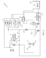
- FIG. 1 is a simplified schematic diagram of an exemplary embodiment of a hybrid fuel delivery and control system for a gas turbine engine
- FIG. 2 is a schematic representation of an alternative embodiment of a hybrid fuel delivery and control system for a gas turbine engine.
- FIG. 1 a simplified schematic diagram of one embodiment of a fuel delivery and control system for a gas turbine engine, such as a turbofan jet aircraft engine, is depicted.
- the system 100 includes a fuel source 102, an electric fuel metering pump 104, a mechanically-driven fuel pump 106, a fuel shut-off valve 108, and a motor controller 112.
- the fuel source 102 which is preferably implemented as one or more tanks, stores fuel that is to be supplied to a plurality of fuel loads 114 (e.g. 114-1, 114-2, 114-3,... 114-N).
- the number and type of fuel loads may vary, and may include one or more gas turbine engine fuel manifolds 114-1, one or more surge valves 114-2, one or more variable geometry actuators 114-3, and one or more bleed valves 114-4, just to name a few.
- the fuel loads 114 are preferably classified as primary and secondary fuel loads based, for example, on functionality. Though the classifications may vary, the one or more gas turbine engine fuel manifolds 114-1, which are disposed within the combustor zone of a gas turbine engine 115, are typically classified as primary fuel loads.
- the one or more surge valves 114-2, the one or more variable geometry actuators 114-3, and the one or more bleed valves 114-4 are typically classified as secondary fuel loads. Although not depicted as such for clarity, it will be appreciated that one or more of the secondary fuel loads may additionally be disposed within the gas turbine engine 115.
- a supply line 116 is coupled to the fuel source 102 and, via the pumps 104, 106, delivers the fuel to the fuel loads 114. It is noted that the supply line 116 is, for convenience, depicted and described as including a priority flow line 116-1 and a secondary flow line 116-2.
- the priority flow line 116-1 preferably delivers fuel to the primary fuel loads (e.g., 114-1), and the secondary flow line 116-2 preferably delivers fuel to the secondary fuel loads (e.g., 114-2, 114-3, 114-4,... 114-N).
- the electric fuel metering pump 104 is positioned in flow-series in the supply line 116 and includes a fuel inlet 103 and a fuel outlet 105.
- the electric fuel metering pump 104 draws fuel into its fuel inlet 103 and supplies the fuel at a relatively high pressure, via it fuel outlet 105, to the priority flow line 116-1.
- the electric fuel metering pump 104 may be variously configured, but in the depicted embodiment it includes an electric motor 118 and a fluid pump 122.
- the electric motor 118 is configured, upon being supplied with electrical current, to generate and supply drive torque to the electric fuel metering fluid pump 122.
- the electric fuel metering fluid pump 122 is preferably a positive displacement pump such as, for example, a variable displacement piston pump, and includes the fuel inlet 103 and the fuel outlet 105.
- the electric fuel metering fluid pump 122 is configured, upon receiving the drive torque from the electric motor 122, to draw fuel into the fuel inlet 103 and discharge the fuel, at a relatively high pump discharge pressure, such as up to 1200 psig, out the fuel outlet 105 and to the priority flow line 116-1.
- the electric motor 118 is preferably a brushless motor, though it will be appreciated that the electric motor 118 could be implemented using any one of numerous types of AC or DC motors. It will additionally be appreciated that the electric fuel metering pump 104 could be implemented with more than one electric motor 118.
- the mechanically-driven fuel pump 106 is also positioned in flow-series in the supply line 116, and includes a fuel inlet 107 and a fuel outlet 109.
- the mechanically-driven fuel pump 106 draws fuel into its fuel inlet 107 and discharges the fuel, also at a relatively high pressure, via its fuel outlet 107, to the electric fuel metering pump fuel inlet 103 and to the secondary flow line 116-2.
- the mechanically-driven pump 106 may be variously implemented, but in the depicted embodiment it includes an input shaft 124 and a fluid pump 126.
- the input shaft 124 is coupled to, and receives an engine drive torque from, the gas turbine engine 115.
- the input shaft 115 is coupled to the gas turbine engine gearbox 117 and, upon receipt of the engine drive torque, supplies a pump drive torque to the fluid pump 126.
- the fluid pump 126 is preferably a high pressure pump, such as a positive displacement pump, and is coupled to the input shaft 124.
- the fluid pump 126 is responsive to the pump drive torque supplied from the input shaft 124 to draw fuel into its fuel inlet 107 and discharge the fuel from its fuel outlet 109 for supply to the electric fuel metering pump fuel inlet 103 and, via the secondary flow line 116-2, to the plurality of secondary fuel loads 114-2, 114-3, 114-4,. .. 114-N. It may thus be appreciated that fuel is supplied to the secondary fuel loads 114-2, 114-3, 114-4,... 114-N independent of the electric fuel metering pump 104.
- the system 100 includes an additional booster pump 118, such as a relatively low horsepower centrifugal pump.
- the booster pump 118 takes a suction directly on the fuel source 102 and provides sufficient suction head for the electric fuel metering pump 104 and the mechanically-driven pump 106.
- the boost pump 118 may be either mechanically driven by the engine, or electrically driven by a non-illustrated motor.
- the boost pump 118 may, in some embodiments, not be included.
- the system 100 may additionally include a low pressure pump within the fuel tank(s) 102 to supply fuel to the boost pump 104.
- the fuel shut-off valve 108 is positioned in flow-series in the priority flow line 116-1 downstream of the electric fuel metering pump 104. More specifically, the fuel shut-off valve 108 is mounted on the priority flow line 116-1 between the electric fuel metering pump 104 and the one or more fuel manifolds 114-1.
- the fuel shut-off valve 108 includes an inlet 111 that is in fluid communication with the electric fuel metering pump outlet 105, an outlet 113 that is in fluid communication with the one or more fuel manifolds 114-1, and is movable between a closed position and an open position. In the closed position, fuel flow through the fuel shut-off valve 108 and to the one or more fuel manifolds 114-1 is prohibited.
- fuel flow through the fuel shut-off valve 108 may occur. It will be appreciated that the fuel shut-off valve 108 may not be included in some embodiments. It will additionally be appreciated that the fuel shut-off valve 108, at least in some embodiments, may include additional flow ports. For example, as will be briefly described below, the fuel shut-off valve 108 may be implemented as a three-way valve.
- the controller 112 is configured to control the supply of electrical current to the electric fuel metering pump 104, and more specifically to the electric motor 118, to thereby control the drive torque supplied to the fuel metering fluid pump 122.
- the controller 112 is adapted to receive one or more signals 128 representative of the drive torque needed to drive the fuel metering fluid pump 122 at a speed to deliver a desired fuel flow rate to the one or more engine fuel manifolds 114-1.
- the motor controller 112 in response to the command signal 128, controls the current supplied to the electric motor 118 such that it generates the needed drive torque.
- the system 100 could be implemented with more than one controller 112, most notably in system embodiments that include more than one electric motor 118.
- the system 100 further includes an engine control 150.
- the engine control 150 which may be implemented as a Full Authority Digital Engine Controller (FADEC) or other electronic engine controller (EEC), controls the flow rate of fuel to the one or more fuel manifolds 114-1. To do so, the engine control 150 receives various input signals and controls the fuel flow rate to the one or more fuel manifolds 114-1 accordingly. In particular, the engine control 150 receives one or more signals 152 representative of a desired fuel flow to be delivered to the one or more engine fuel manifolds 114-1. The engine control 150, in response to the one or more signals 152, determines an appropriate motor speed command, and automatically generates the above-mentioned command signal 128 that is supplied to the controller 112. It will be appreciated that in some embodiments, as depicted using the dotted line in FIG. 1 , the controller 112 and the engine control 150 may be integrated together.
- FADEC Full Authority Digital Engine Controller
- EEC electronic engine controller
- the system 100 depicted in FIG. 1 may be implemented with additional components and associated interconnections.
- the system 100 may be implemented with one or more check valves, one or more relief valves, a starter load valve, a flow divider valve, and an ecology valve, just to name a few.
- the above-described components may be variously configured.
- FIG. 2 At least one alternative system embodiment is depicted in FIG. 2 , and the associated differences of this alternative embodiment, with respect to the system 100 of FIG. 1 , will briefly be described. Before doing so, however, it is noted that like reference numerals in FIGS. 1 and 2 refer to like components, the descriptions of which will not be repeated.
- this system 200 includes two check valves 202, 204, a relief valve 206, a start load valve 208, a flow divider/pressurizing valve 212, and an ecology valve 214.
- the fuel shut-off valve 108 is implemented as a 3-way fuel shut-off valve. It is noted that the functions of each of the additional components included in the system 200 of FIG. 2 is readily apparent to the skilled artisan. As such, further description of each is not provided herein.
- the systems 100, 200 depicted in described herein include a mechanically-driven fuel pump 106 in flow-series with an electric fuel metering pump 104 and with the plurality of secondary fuel loads 114-2, 114-3, 114-4,... 114-N.
- the electric fuel metering pump 104 is used to supply fuel only to primary fuel loads, such as one or more engine fuel manifolds 114-1.
- primary fuel loads such as one or more engine fuel manifolds 114-1.
- fuel is supplied to the secondary fuel loads 114-2, 114-3, 114-4,... 114-N independent of the electric fuel metering pump 104, which advantageously reduces the electrical power consumption of the electric fuel metering pump 104.
- this configuration provides the ability to refill the one or more engine fuel manifolds 114-1 independent of engine speed during an engine start cycle.
Landscapes
- Engineering & Computer Science (AREA)
- Chemical & Material Sciences (AREA)
- Combustion & Propulsion (AREA)
- Mechanical Engineering (AREA)
- General Engineering & Computer Science (AREA)
- Combined Controls Of Internal Combustion Engines (AREA)
- Control Of Positive-Displacement Pumps (AREA)
Abstract
A turbine engine fuel supply system (100) includes a priority flow line (116), a plurality of secondary fuel loads (114), an electric fuel metering pump (104), and a mechanically-driven fuel pump (106). The priority flow line (116) is used to supply fuel to one or more gas turbine engine fuel manifolds (114). The electric fuel metering pump (104) has a fuel inlet (103) and a fuel outlet (105), and is adapted to be selectively energized and, upon being energized, to draw fuel into its fuel inlet and discharge the fuel from its fuel outlet for supply to the priority flow line (116). The mechanically-driven fuel pump (106) has a fuel inlet (107), and a fuel outlet (109) that is in fluid communication with the electric fuel metering pump fuel inlet (103) and the plurality of secondary fuel loads (114). As such, fuel may be supplied to the secondary fuel loads (114) independent of the electric fuel metering pump (104), which advantageously reduces the electrical power consumption of the electric fuel metering pump.
Description
- The present invention generally relates to turbine engine fuel supply systems and, more particularly, to a turbine engine fuel supply system that is configured as a hybrid of electrically-driven and mechanically-driven fuel supply systems.
- Typical gas turbine engine fuel supply systems include a fuel source, such as a fuel tank, and one or more pumps. The one or more pumps draw fuel from the fuel tank and deliver pressurized fuel to one or more primary fuel loads and to one or more secondary fuel loads via one or more supply lines. Generally, the primary fuel loads, which include the fuel manifolds in the engine combustor, are supplied with fuel via, for example, a priority flow line. The secondary fuel loads, which may include a motive flow valve and regulator, one or more variable geometry actuators, and one or more bleed valves, are supplied with fuel via, for example, a secondary flow line.
- Recently, there has been a desire to implement fuel supply systems with electric pumps. In such systems, fuel flow is controlled by, for example, controlling the speed of the electric pump, rather than the position of a metering valve and/or a bypass flow valve. Preferably, the electric pump is sized to supply the maximum fuel flow that may be needed by allow of the system loads. Thus, for systems that include one or more secondary fuel loads, the electric pump may need to be sized to supply a higher flow rate than what is needed by just the primary fuel loads. As a result, the overall fuel system design may exhibit certain undesirable drawbacks. For example, a relatively larger electric pump may generate excessive fuel system heat, and/or may increase overall fuel system weight and costs.
- Hence, there is a need for a fuel supply system that uses an electric pump to control fuel flow to one or more primary loads and that is able to supply fuel to secondary fuel loads without generating excessive fuel system heat, and/or increasing overall fuel system weight and/or costs. The present invention addresses one or more of these needs.
- In one embodiment, and by way of example only, a turbine engine fuel supply system includes a priority flow line, a plurality of secondary fuel loads, an electric fuel metering pump, and a mechanically-driven fuel pump. The priority flow line is configured to supply fuel to one or more gas turbine engine fuel manifolds. The electric fuel metering pump has a fuel inlet and a fuel outlet, and is adapted to be selectively energized and, upon being energized, to draw fuel into its fuel inlet and discharge the fuel from its fuel outlet for supply to the priority flow line. The mechanically-driven fuel pump has a fuel inlet, and a fuel outlet that is in fluid communication with the electric fuel metering pump fuel inlet and the plurality of secondary fuel loads.
- In another exemplary embodiment, a gas turbine engine system includes a gas turbine engine, a plurality of secondary fuel loads, an electric fuel metering pump, and a mechanically-driven fuel pump. The gas turbine engine includies one or more fuel manifolds and a gearbox. The electric fuel metering pump has a fuel inlet and a fuel outlet, and is adapted to be selectively energized and, upon being energized, to draw fuel into its fuel inlet and supply the fuel, via its fuel outlet, to the one or more fuel manifolds. The mechanically-driven fuel pump is coupled to the gas turbine engine gearbox to be driven thereby, The mechanically-driven fuel pump has a fuel inlet, and a fuel outlet that is in fluid communication with the electric fuel metering pump fuel inlet and the plurality of secondary fuel loads.
- Furthermore, other desirable features and characteristics of the present invention will become apparent from the subsequent detailed description of the invention and the appended claims, taken in conjunction with the accompanying drawings and this
- The present invention will hereinafter be described in conjunction with the following drawing figures, wherein like numerals denote like elements, and wherein:
-
FIG. 1 is a simplified schematic diagram of an exemplary embodiment of a hybrid fuel delivery and control system for a gas turbine engine; and -
FIG. 2 is a schematic representation of an alternative embodiment of a hybrid fuel delivery and control system for a gas turbine engine. - The following detailed description is merely exemplary in nature and is not intended to limit the invention or the application and uses of the invention. Furthermore, there is no intention to be bound by any theory presented in the preceding background or the following detailed description. In this regard, although an embodiment of the invention is described as being implemented in an aircraft and for a gas turbine engine, it will be appreciated that the invention may be implemented in numerous and varied end-use environments where fuel flow to primary and secondary fuel loads is controlled..
- Turning now to
FIG. 1 , a simplified schematic diagram of one embodiment of a fuel delivery and control system for a gas turbine engine, such as a turbofan jet aircraft engine, is depicted. Thesystem 100 includes afuel source 102, an electricfuel metering pump 104, a mechanically-drivenfuel pump 106, a fuel shut-offvalve 108, and amotor controller 112. Thefuel source 102, which is preferably implemented as one or more tanks, stores fuel that is to be supplied to a plurality of fuel loads 114 (e.g. 114-1, 114-2, 114-3,... 114-N). It will be appreciated that the number and type of fuel loads may vary, and may include one or more gas turbine engine fuel manifolds 114-1, one or more surge valves 114-2, one or more variable geometry actuators 114-3, and one or more bleed valves 114-4, just to name a few. Thefuel loads 114 are preferably classified as primary and secondary fuel loads based, for example, on functionality. Though the classifications may vary, the one or more gas turbine engine fuel manifolds 114-1, which are disposed within the combustor zone of agas turbine engine 115, are typically classified as primary fuel loads. Moreover, the one or more surge valves 114-2, the one or more variable geometry actuators 114-3, and the one or more bleed valves 114-4 are typically classified as secondary fuel loads. Although not depicted as such for clarity, it will be appreciated that one or more of the secondary fuel loads may additionally be disposed within thegas turbine engine 115. - A
supply line 116 is coupled to thefuel source 102 and, via thepumps fuel loads 114. It is noted that thesupply line 116 is, for convenience, depicted and described as including a priority flow line 116-1 and a secondary flow line 116-2. The priority flow line 116-1 preferably delivers fuel to the primary fuel loads (e.g., 114-1), and the secondary flow line 116-2 preferably delivers fuel to the secondary fuel loads (e.g., 114-2, 114-3, 114-4,... 114-N). - The electric
fuel metering pump 104 is positioned in flow-series in thesupply line 116 and includes afuel inlet 103 and afuel outlet 105. The electricfuel metering pump 104 draws fuel into itsfuel inlet 103 and supplies the fuel at a relatively high pressure, via itfuel outlet 105, to the priority flow line 116-1. The electricfuel metering pump 104 may be variously configured, but in the depicted embodiment it includes anelectric motor 118 and afluid pump 122. Theelectric motor 118 is configured, upon being supplied with electrical current, to generate and supply drive torque to the electric fuelmetering fluid pump 122. The electric fuelmetering fluid pump 122 is preferably a positive displacement pump such as, for example, a variable displacement piston pump, and includes thefuel inlet 103 and thefuel outlet 105. The electric fuelmetering fluid pump 122 is configured, upon receiving the drive torque from theelectric motor 122, to draw fuel into thefuel inlet 103 and discharge the fuel, at a relatively high pump discharge pressure, such as up to 1200 psig, out thefuel outlet 105 and to the priority flow line 116-1. It will be appreciated that theelectric motor 118 is preferably a brushless motor, though it will be appreciated that theelectric motor 118 could be implemented using any one of numerous types of AC or DC motors. It will additionally be appreciated that the electricfuel metering pump 104 could be implemented with more than oneelectric motor 118. - The mechanically-driven
fuel pump 106 is also positioned in flow-series in thesupply line 116, and includes afuel inlet 107 and afuel outlet 109. The mechanically-drivenfuel pump 106 draws fuel into itsfuel inlet 107 and discharges the fuel, also at a relatively high pressure, via itsfuel outlet 107, to the electric fuel meteringpump fuel inlet 103 and to the secondary flow line 116-2. The mechanically-drivenpump 106 may be variously implemented, but in the depicted embodiment it includes aninput shaft 124 and afluid pump 126. Theinput shaft 124 is coupled to, and receives an engine drive torque from, thegas turbine engine 115. Specifically, at least in the depicted embodiment, theinput shaft 115 is coupled to the gasturbine engine gearbox 117 and, upon receipt of the engine drive torque, supplies a pump drive torque to thefluid pump 126. Thefluid pump 126 is preferably a high pressure pump, such as a positive displacement pump, and is coupled to theinput shaft 124. Thefluid pump 126 is responsive to the pump drive torque supplied from theinput shaft 124 to draw fuel into itsfuel inlet 107 and discharge the fuel from itsfuel outlet 109 for supply to the electric fuel meteringpump fuel inlet 103 and, via the secondary flow line 116-2, to the plurality of secondary fuel loads 114-2, 114-3, 114-4,. .. 114-N. It may thus be appreciated that fuel is supplied to the secondary fuel loads 114-2, 114-3, 114-4,... 114-N independent of the electricfuel metering pump 104. - In the depicted embodiment, the
system 100 includes anadditional booster pump 118, such as a relatively low horsepower centrifugal pump. Thebooster pump 118, if included, takes a suction directly on thefuel source 102 and provides sufficient suction head for the electricfuel metering pump 104 and the mechanically-drivenpump 106. It will additionally be appreciated that theboost pump 118 may be either mechanically driven by the engine, or electrically driven by a non-illustrated motor. Moreover, theboost pump 118 may, in some embodiments, not be included. Although not depicted, it will be appreciated that thesystem 100 may additionally include a low pressure pump within the fuel tank(s) 102 to supply fuel to theboost pump 104. - The fuel shut-off
valve 108 is positioned in flow-series in the priority flow line 116-1 downstream of the electricfuel metering pump 104. More specifically, the fuel shut-offvalve 108 is mounted on the priority flow line 116-1 between the electricfuel metering pump 104 and the one or more fuel manifolds 114-1. The fuel shut-offvalve 108 includes aninlet 111 that is in fluid communication with the electric fuelmetering pump outlet 105, anoutlet 113 that is in fluid communication with the one or more fuel manifolds 114-1, and is movable between a closed position and an open position. In the closed position, fuel flow through the fuel shut-offvalve 108 and to the one or more fuel manifolds 114-1 is prohibited. Conversely, in the open position, fuel flow through the fuel shut-offvalve 108 may occur. It will be appreciated that the fuel shut-offvalve 108 may not be included in some embodiments. It will additionally be appreciated that the fuel shut-offvalve 108, at least in some embodiments, may include additional flow ports. For example, as will be briefly described below, the fuel shut-offvalve 108 may be implemented as a three-way valve. - The
controller 112 is configured to control the supply of electrical current to the electricfuel metering pump 104, and more specifically to theelectric motor 118, to thereby control the drive torque supplied to the fuelmetering fluid pump 122. Preferably, thecontroller 112 is adapted to receive one ormore signals 128 representative of the drive torque needed to drive the fuelmetering fluid pump 122 at a speed to deliver a desired fuel flow rate to the one or more engine fuel manifolds 114-1. Themotor controller 112, in response to thecommand signal 128, controls the current supplied to theelectric motor 118 such that it generates the needed drive torque. It will be appreciated that in some embodiments, thesystem 100 could be implemented with more than onecontroller 112, most notably in system embodiments that include more than oneelectric motor 118. - The
system 100, at least in the depicted embodiment, further includes anengine control 150. Theengine control 150, which may be implemented as a Full Authority Digital Engine Controller (FADEC) or other electronic engine controller (EEC), controls the flow rate of fuel to the one or more fuel manifolds 114-1. To do so, theengine control 150 receives various input signals and controls the fuel flow rate to the one or more fuel manifolds 114-1 accordingly. In particular, theengine control 150 receives one ormore signals 152 representative of a desired fuel flow to be delivered to the one or more engine fuel manifolds 114-1. Theengine control 150, in response to the one ormore signals 152, determines an appropriate motor speed command, and automatically generates the above-mentionedcommand signal 128 that is supplied to thecontroller 112. It will be appreciated that in some embodiments, as depicted using the dotted line inFIG. 1 , thecontroller 112 and theengine control 150 may be integrated together. - The
system 100 depicted inFIG. 1 may be implemented with additional components and associated interconnections. For example, thesystem 100 may be implemented with one or more check valves, one or more relief valves, a starter load valve, a flow divider valve, and an ecology valve, just to name a few. Moreover, as was alluded to above at least with respect to the fuel shut-offvalve 108, the above-described components may be variously configured. At least one alternative system embodiment is depicted inFIG. 2 , and the associated differences of this alternative embodiment, with respect to thesystem 100 ofFIG. 1 , will briefly be described. Before doing so, however, it is noted that like reference numerals inFIGS. 1 and2 refer to like components, the descriptions of which will not be repeated. - Turning now to
FIG. 2 , it is seen that in addition to the components that are common with thesystem 100 ofFIG. 1 , thissystem 200 includes twocheck valves relief valve 206, astart load valve 208, a flow divider/pressurizingvalve 212, and anecology valve 214. Moreover, the fuel shut-offvalve 108 is implemented as a 3-way fuel shut-off valve. It is noted that the functions of each of the additional components included in thesystem 200 ofFIG. 2 is readily apparent to the skilled artisan. As such, further description of each is not provided herein. - The
systems fuel pump 106 in flow-series with an electricfuel metering pump 104 and with the plurality of secondary fuel loads 114-2, 114-3, 114-4,... 114-N. The electricfuel metering pump 104 is used to supply fuel only to primary fuel loads, such as one or more engine fuel manifolds 114-1. With this configuration, fuel is supplied to the secondary fuel loads 114-2, 114-3, 114-4,... 114-N independent of the electricfuel metering pump 104, which advantageously reduces the electrical power consumption of the electricfuel metering pump 104. Moreover, in thosesystems 200 that include anecology valve 214, this configuration provides the ability to refill the one or more engine fuel manifolds 114-1 independent of engine speed during an engine start cycle. - While at least one exemplary embodiment has been presented in the foregoing detailed description of the invention, it should be appreciated that a vast number of variations exist. It should also be appreciated that the exemplary embodiment or exemplary embodiments are only examples, and are not intended to limit the scope, applicability, or configuration of the invention in any way. Rather, the foregoing detailed description will provide those skilled in the art with a convenient road map for implementing an exemplary embodiment of the invention. It being understood that various changes may be made in the function and arrangement of elements described in an exemplary embodiment without departing from the scope of the invention as set forth in the appended claims.
Claims (10)
- A turbine engine fuel supply system (100), comprising:a priority flow line (116) configured to supply fuel to one or more gas turbine engine fuel manifolds (114);a plurality of secondary fuel loads (114);an electric fuel metering pump (104) having a fuel inlet and a fuel outlet, the electric fuel metering pump (104) adapted to be selectively energized and, upon being energized, to draw fuel into its fuel inlet and discharge the fuel from its fuel outlet for supply to the priority flow line (116); anda mechanically-driven fuel pump (106) having a fuel inlet and a fuel outlet, the mechanically-driven fuel pump (106) outlet in fluid communication with the electric fuel metering pump (104) fuel inlet and the plurality of secondary fuel loads (114).
- The system of Claim 1, further comprising:a fuel shut-off valve (108) mounted on the priority flow line (116), the fuel shut-off valve (108) having at least an inlet and an outlet, the fuel shut-off valve (108) inlet in fluid communication with the electric fuel metering pump (104) fluid outlet, the fuel shut-off valve (108) movable between an open position, in which fuel discharged from the electric fuel metering pump (104) fuel outlet flows through the fuel shut-off valve (108) outlet, and a closed position, in which fuel discharged from the electric fuel metering pump (104) fuel outlet does not flow through the fuel shut-off valve (108) outlet.
- The system of Claim 1, wherein the electric fuel metering pump (104) comprises:an electric motor (118) adapted to be selectively energized and, upon being energized, to supply a drive torque; anda fluid pump (122) having a fuel inlet and a fuel outlet, the fluid pump (122) coupled to the electric motor (118) to receive the drive torque therefrom and operable, upon receipt of the drive torque, to draw fuel into its fuel inlet and discharge the fuel from its fuel outlet for supply to the priority flow line (116).
- The system of Claim 1, wherein the mechanically-driven pump (106) comprises:a fluid pump (122) having a fuel inlet and a fuel outlet, the fluid pump (122) coupled to receive a pump drive torque and operable, upon receipt of the drive torque, to draw fuel into its fuel inlet and discharge the fuel from its fuel outlet for supply to the electric fuel metering pump (104) fuel inlet and the plurality of secondary fuel loads (114); andan input shaft (124) adapted to be coupled to a gas turbine engine gearbox (117) to receive an engine drive torque therefrom and supply the pump drive torque to the fluid pump (122).
- The system of Claim 1, wherein the secondary fuel loads (114) comprise:a surge valve actuator (114-2);a bleed valve actuator (114-3); anda gas turbine engine inlet guide vane actuator (114-4).
- The system of Claim 1, further comprising:an ecology valve (214) mounted on the priority flow line (116) downstream of the electric fuel metering pump (104).
- The system of Claim 1, further comprising:a fuel tank (102) adapted to have the fuel stored therein and in fluid communication with the electric fuel metering pump (104) fuel inlet and the mechanically-driven fuel pump (106) fuel inlet.
- The system of Claim 7, further comprising:a boost pump disposed between the fuel tank and the electric fuel metering pump (104) fuel inlet and the mechanically-driven fuel pump (106) fuel inlet.
- The system of Claim 1, further comprising:a controller (112) in electrical communication with, and operable to selectively energize, the electric fuel metering pump (104).
- The system of Claim 9, wherein:the controller (112) is adapted to receive one or more signals (128) representative of a desired fuel flow to the one or more engine fuel manifolds (114); andthe controller (112) is configured to be responsive to the one or more signals (128) to selectively energize the electric fuel metering pump (104) to deliver the desired fuel flow.
Applications Claiming Priority (1)
| Application Number | Priority Date | Filing Date | Title |
|---|---|---|---|
| US12/034,778 US8127548B2 (en) | 2008-02-21 | 2008-02-21 | Hybrid electrical/mechanical turbine engine fuel supply system |
Publications (1)
| Publication Number | Publication Date |
|---|---|
| EP2093400A2 true EP2093400A2 (en) | 2009-08-26 |
Family
ID=40637126
Family Applications (1)
| Application Number | Title | Priority Date | Filing Date |
|---|---|---|---|
| EP09152340A Withdrawn EP2093400A2 (en) | 2008-02-21 | 2009-02-07 | Hybrid electrical-mechanical turbine engine fuel supply system |
Country Status (2)
| Country | Link |
|---|---|
| US (1) | US8127548B2 (en) |
| EP (1) | EP2093400A2 (en) |
Cited By (9)
| Publication number | Priority date | Publication date | Assignee | Title |
|---|---|---|---|---|
| FR2971548A1 (en) * | 2011-02-11 | 2012-08-17 | Snecma | FUEL SUPPLY SYSTEM WITH MULTIPLE PUMPING MEANS |
| EP2799772A1 (en) * | 2013-04-29 | 2014-11-05 | Hamilton Sundstrand Corporation | Self powered fluid metering units |
| FR3020403A1 (en) * | 2014-04-28 | 2015-10-30 | Snecma | FLUID SUPPLY CIRCUIT FOR VARIABLE GEOMETRIES WITHOUT VOLUMETRIC PUMP AND COMBUSTION CHAMBER SUPPLY CIRCUIT WITH ELECTRIC VOLUMETRIC PUMP |
| FR3020404A1 (en) * | 2014-04-28 | 2015-10-30 | Snecma | FLUID SUPPLY CIRCUIT FOR VARIABLE TURBOMACHINE GEOMETRIES WITHOUT VOLUMETRIC PUMP |
| WO2015166177A1 (en) * | 2014-04-28 | 2015-11-05 | Snecma | Variable geometries fluid supply circuit for a turbomachine without volumetric pump |
| FR3021360A1 (en) * | 2014-05-21 | 2015-11-27 | Snecma | VARIABLE GEOMETRY FLUID SUPPLY CIRCUIT AND INJECTION SYSTEM SUPPLY CIRCUIT |
| US9206775B2 (en) | 2012-02-01 | 2015-12-08 | United Technologies Corporation | Fuel preheating using electric pump |
| US9316157B2 (en) | 2012-02-01 | 2016-04-19 | Hamilton Sundstrand Corporation | Fuel system for starting an APU using a hybrid pump arrangement |
| EP3020941A1 (en) * | 2014-11-14 | 2016-05-18 | Hamilton Sundstrand Corporation | Aircraft fuel system |
Families Citing this family (19)
| Publication number | Priority date | Publication date | Assignee | Title |
|---|---|---|---|---|
| US8046983B2 (en) * | 2008-09-11 | 2011-11-01 | Honeywell International Inc. | Ecology valve fuel return system for gas turbine engine |
| US8286432B2 (en) * | 2008-11-25 | 2012-10-16 | Honeywell International Inc. | Electric power generating turbine engine fuel supply system |
| FR2974149B1 (en) * | 2011-04-14 | 2015-09-25 | Snecma | FUEL SYSTEM COMPRISING MEANS FOR MONITORING A PUMP |
| CN202832796U (en) * | 2012-03-30 | 2013-03-27 | 通用电气公司 | Fuel supply system |
| US9091212B2 (en) * | 2013-03-27 | 2015-07-28 | Hamilton Sundstrand Corporation | Fuel and actuation system for gas turbine engine |
| US9885287B2 (en) | 2014-09-11 | 2018-02-06 | Honeywell International Inc. | Gas turbine engine mechanical-electrical hybrid fuel delivery system |
| CN107044350B (en) * | 2017-04-24 | 2019-04-23 | 中国航发沈阳发动机研究所 | A kind of fluid power system and the gas turbine with it |
| US11187229B2 (en) | 2017-06-14 | 2021-11-30 | Hamilton Sundstrand Corporation | Demand fuel systems for turbomachines |
| US20190002117A1 (en) | 2017-06-30 | 2019-01-03 | General Electric Company | Propulsion system for an aircraft |
| RU2674806C1 (en) * | 2017-10-05 | 2018-12-13 | Акционерное общество "Объединенная двигателестроительная корпорация" (АО "ОДК") | Necessary pressure and fuel consumption in the aircraft gas turbine engine fuel system development method |
| US11015480B2 (en) | 2018-08-21 | 2021-05-25 | General Electric Company | Feed forward load sensing for hybrid electric systems |
| US11332256B2 (en) | 2018-08-21 | 2022-05-17 | General Electric Company | Fault tolerant hybrid electric propulsion system for an aerial vehicle |
| US20210079848A1 (en) | 2019-03-20 | 2021-03-18 | United Technologies Corporation | Secondary fuel flow demand fuel pumping system |
| US12025054B2 (en) * | 2019-04-05 | 2024-07-02 | General Electric Company | Pump mixer separator unit |
| US12253029B2 (en) * | 2023-08-07 | 2025-03-18 | Hamilton Sundstrand Corporation | Fuel system for dual use gas turbine engine main fuel pump |
| GB202319150D0 (en) | 2023-12-14 | 2024-01-31 | Rolls Royce Plc | Fueldraulic heat management system |
| GB202319159D0 (en) | 2023-12-14 | 2024-01-31 | Rolls Royce Plc | Fueldraulic actuation |
| GB202319147D0 (en) * | 2023-12-14 | 2024-01-31 | Rolls Royce Plc | Actuated gas turbine engine systems |
| US12352211B1 (en) * | 2024-02-28 | 2025-07-08 | Hamilton Sundstrand Corporation | Dual pump electrified fuel system with parallelism |
Family Cites Families (16)
| Publication number | Priority date | Publication date | Assignee | Title |
|---|---|---|---|---|
| US3711044A (en) * | 1971-03-17 | 1973-01-16 | Garrett Corp | Automatic interface control system |
| US4208871A (en) * | 1977-08-29 | 1980-06-24 | The Garrett Corporation | Fuel control system |
| US5117625A (en) * | 1988-05-23 | 1992-06-02 | Sundstrand Corporation | Integrated bleed load compressor and turbine control system |
| US5118258A (en) | 1990-09-04 | 1992-06-02 | United Technologies Corporation | Dual pump fuel delivery system |
| US5116362A (en) * | 1990-12-03 | 1992-05-26 | United Technologies Corporation | Fuel metering and actuation system |
| US6079198A (en) * | 1998-04-29 | 2000-06-27 | General Electric Co. | Pressure compensated fuel delivery system for the combustors of turbomachinery |
| US6314998B1 (en) | 1999-07-27 | 2001-11-13 | Alliedsignal Inc. | Fuel divider and ecology system for a gas turbine engine |
| US6675570B2 (en) * | 2000-06-15 | 2004-01-13 | Argo-Tech Corporation | Low-cost general aviation fuel control system |
| GB0023727D0 (en) * | 2000-09-27 | 2000-11-08 | Lucas Industries Ltd | Control system |
| US6655151B2 (en) * | 2001-09-07 | 2003-12-02 | Honeywell International, Inc. | Method for controlling fuel flow to a gas turbine engine |
| US7114336B2 (en) | 2004-01-30 | 2006-10-03 | Woodward Governor Company | Flow pulsing valve and fuel supply system for a turbine engine incorporating same |
| US7216487B2 (en) * | 2004-09-16 | 2007-05-15 | Hamilton Sundstrand | Metering demand fuel system for gas turbine engines |
| EP1819914A2 (en) | 2004-11-19 | 2007-08-22 | Goodrich Pump & Engine Control Systems, Inc. | Two-stage fuel pump for gas turbines |
| US8291886B2 (en) * | 2007-02-12 | 2012-10-23 | Honeywell International Inc. | Actuator flow compensated direct metering fuel control system and method |
| US8286432B2 (en) * | 2008-11-25 | 2012-10-16 | Honeywell International Inc. | Electric power generating turbine engine fuel supply system |
| US8276360B2 (en) * | 2009-05-22 | 2012-10-02 | Hamilton Sundstrand Corporation | Dual-pump fuel system and method for starting a gas turbine engine |
-
2008
- 2008-02-21 US US12/034,778 patent/US8127548B2/en active Active
-
2009
- 2009-02-07 EP EP09152340A patent/EP2093400A2/en not_active Withdrawn
Cited By (14)
| Publication number | Priority date | Publication date | Assignee | Title |
|---|---|---|---|---|
| FR2971548A1 (en) * | 2011-02-11 | 2012-08-17 | Snecma | FUEL SUPPLY SYSTEM WITH MULTIPLE PUMPING MEANS |
| US9206775B2 (en) | 2012-02-01 | 2015-12-08 | United Technologies Corporation | Fuel preheating using electric pump |
| US9316157B2 (en) | 2012-02-01 | 2016-04-19 | Hamilton Sundstrand Corporation | Fuel system for starting an APU using a hybrid pump arrangement |
| EP2799772A1 (en) * | 2013-04-29 | 2014-11-05 | Hamilton Sundstrand Corporation | Self powered fluid metering units |
| US9618913B2 (en) | 2013-04-29 | 2017-04-11 | Hamilton Sundstrand Corporation | Self powered fluid metering units |
| FR3020404A1 (en) * | 2014-04-28 | 2015-10-30 | Snecma | FLUID SUPPLY CIRCUIT FOR VARIABLE TURBOMACHINE GEOMETRIES WITHOUT VOLUMETRIC PUMP |
| WO2015166177A1 (en) * | 2014-04-28 | 2015-11-05 | Snecma | Variable geometries fluid supply circuit for a turbomachine without volumetric pump |
| FR3020403A1 (en) * | 2014-04-28 | 2015-10-30 | Snecma | FLUID SUPPLY CIRCUIT FOR VARIABLE GEOMETRIES WITHOUT VOLUMETRIC PUMP AND COMBUSTION CHAMBER SUPPLY CIRCUIT WITH ELECTRIC VOLUMETRIC PUMP |
| US9909498B2 (en) | 2014-04-28 | 2018-03-06 | Safran Aircraft Engines | Variable geometries fluid supply circuit for a turbomachine without volumetric pump |
| FR3021360A1 (en) * | 2014-05-21 | 2015-11-27 | Snecma | VARIABLE GEOMETRY FLUID SUPPLY CIRCUIT AND INJECTION SYSTEM SUPPLY CIRCUIT |
| GB2528365A (en) * | 2014-05-21 | 2016-01-20 | Snecma | Variable geometries fluid supply circuit and injection system supply circuit |
| GB2528365B (en) * | 2014-05-21 | 2020-05-06 | Snecma | Variable geometries fluid supply circuit and injection system supply circuit |
| EP3020941A1 (en) * | 2014-11-14 | 2016-05-18 | Hamilton Sundstrand Corporation | Aircraft fuel system |
| US9512783B2 (en) | 2014-11-14 | 2016-12-06 | Hamilton Sundstrand Corporation | Aircraft fuel system |
Also Published As
| Publication number | Publication date |
|---|---|
| US20090211558A1 (en) | 2009-08-27 |
| US8127548B2 (en) | 2012-03-06 |
Similar Documents
| Publication | Publication Date | Title |
|---|---|---|
| US8127548B2 (en) | Hybrid electrical/mechanical turbine engine fuel supply system | |
| US8286432B2 (en) | Electric power generating turbine engine fuel supply system | |
| US8256222B2 (en) | Direct metering fuel control with integral electrical metering pump and actuator servo pump | |
| US8739811B2 (en) | Direct metering fuel system with constant servo flow | |
| US7966995B2 (en) | Dual level pressurization control based on fuel flow to one or more gas turbine engine secondary fuel loads | |
| EP2356329B1 (en) | Fuel delivery and control system | |
| EP2390484B1 (en) | Fuel pumping system for a gas turbine engine | |
| US9885287B2 (en) | Gas turbine engine mechanical-electrical hybrid fuel delivery system | |
| US9617923B2 (en) | Engine fuel control system | |
| US8291886B2 (en) | Actuator flow compensated direct metering fuel control system and method | |
| US9316157B2 (en) | Fuel system for starting an APU using a hybrid pump arrangement | |
| US20100089026A1 (en) | Fuel Delivery and Control System Including a Variable Displacement Actuation Pump Supplementing a Fixed Displacement Main Pump | |
| US9453463B2 (en) | High efficiency, high pressure gas turbine engine fuel supply system | |
| US7560881B2 (en) | Electric drive fuel control system and method | |
| EP2341230A2 (en) | Fuel metering system electrically servoed metering pump | |
| US9068509B2 (en) | Gas turbine engine fuel control thrust control override system | |
| CN103958856B (en) | Fuel system using dual pressure high speed centrifugal pump unit | |
| JP2006083864A (en) | Metering demand fuel system for gas turbine engine | |
| EP2541024B1 (en) | APU fuel system and method | |
| US20250250939A1 (en) | Shaft driven main pump bypass via electric pump | |
| EP4592512A1 (en) | Aircraft fuel system with dual use electric pump |
Legal Events
| Date | Code | Title | Description |
|---|---|---|---|
| PUAI | Public reference made under article 153(3) epc to a published international application that has entered the european phase |
Free format text: ORIGINAL CODE: 0009012 |
|
| 17P | Request for examination filed |
Effective date: 20090207 |
|
| AK | Designated contracting states |
Kind code of ref document: A2 Designated state(s): AT BE BG CH CY CZ DE DK EE ES FI FR GB GR HR HU IE IS IT LI LT LU LV MC MK MT NL NO PL PT RO SE SI SK TR |
|
| AX | Request for extension of the european patent |
Extension state: AL BA RS |
|
| RAP1 | Party data changed (applicant data changed or rights of an application transferred) |
Owner name: HONEYWELL INTERNATIONAL INC. |
|
| STAA | Information on the status of an ep patent application or granted ep patent |
Free format text: STATUS: THE APPLICATION HAS BEEN WITHDRAWN |
|
| 18W | Application withdrawn |
Effective date: 20170406 |