EP2093189A2 - Self-serviceable filter for an oxygengenerating device - Google Patents
Self-serviceable filter for an oxygengenerating device Download PDFInfo
- Publication number
- EP2093189A2 EP2093189A2 EP09152323A EP09152323A EP2093189A2 EP 2093189 A2 EP2093189 A2 EP 2093189A2 EP 09152323 A EP09152323 A EP 09152323A EP 09152323 A EP09152323 A EP 09152323A EP 2093189 A2 EP2093189 A2 EP 2093189A2
- Authority
- EP
- European Patent Office
- Prior art keywords
- feed gas
- self
- generating device
- oxygen
- filter
- Prior art date
- Legal status (The legal status is an assumption and is not a legal conclusion. Google has not performed a legal analysis and makes no representation as to the accuracy of the status listed.)
- Withdrawn
Links
Images


Classifications
-
- C—CHEMISTRY; METALLURGY
- C01—INORGANIC CHEMISTRY
- C01B—NON-METALLIC ELEMENTS; COMPOUNDS THEREOF; METALLOIDS OR COMPOUNDS THEREOF NOT COVERED BY SUBCLASS C01C
- C01B13/00—Oxygen; Ozone; Oxides or hydroxides in general
- C01B13/02—Preparation of oxygen
- C01B13/0229—Purification or separation processes
- C01B13/0248—Physical processing only
-
- C—CHEMISTRY; METALLURGY
- C01—INORGANIC CHEMISTRY
- C01B—NON-METALLIC ELEMENTS; COMPOUNDS THEREOF; METALLOIDS OR COMPOUNDS THEREOF NOT COVERED BY SUBCLASS C01C
- C01B13/00—Oxygen; Ozone; Oxides or hydroxides in general
- C01B13/02—Preparation of oxygen
- C01B13/0229—Purification or separation processes
- C01B13/0248—Physical processing only
- C01B13/0259—Physical processing only by adsorption on solids
-
- B—PERFORMING OPERATIONS; TRANSPORTING
- B01—PHYSICAL OR CHEMICAL PROCESSES OR APPARATUS IN GENERAL
- B01D—SEPARATION
- B01D2259/00—Type of treatment
- B01D2259/45—Gas separation or purification devices adapted for specific applications
- B01D2259/4533—Gas separation or purification devices adapted for specific applications for medical purposes
-
- B—PERFORMING OPERATIONS; TRANSPORTING
- B01—PHYSICAL OR CHEMICAL PROCESSES OR APPARATUS IN GENERAL
- B01D—SEPARATION
- B01D2259/00—Type of treatment
- B01D2259/45—Gas separation or purification devices adapted for specific applications
- B01D2259/455—Gas separation or purification devices adapted for specific applications for transportable use
-
- C—CHEMISTRY; METALLURGY
- C01—INORGANIC CHEMISTRY
- C01B—NON-METALLIC ELEMENTS; COMPOUNDS THEREOF; METALLOIDS OR COMPOUNDS THEREOF NOT COVERED BY SUBCLASS C01C
- C01B2210/00—Purification or separation of specific gases
- C01B2210/0043—Impurity removed
- C01B2210/0046—Nitrogen
-
- C—CHEMISTRY; METALLURGY
- C01—INORGANIC CHEMISTRY
- C01B—NON-METALLIC ELEMENTS; COMPOUNDS THEREOF; METALLOIDS OR COMPOUNDS THEREOF NOT COVERED BY SUBCLASS C01C
- C01B2210/00—Purification or separation of specific gases
- C01B2210/0043—Impurity removed
- C01B2210/0062—Water
-
- Y—GENERAL TAGGING OF NEW TECHNOLOGICAL DEVELOPMENTS; GENERAL TAGGING OF CROSS-SECTIONAL TECHNOLOGIES SPANNING OVER SEVERAL SECTIONS OF THE IPC; TECHNICAL SUBJECTS COVERED BY FORMER USPC CROSS-REFERENCE ART COLLECTIONS [XRACs] AND DIGESTS
- Y10—TECHNICAL SUBJECTS COVERED BY FORMER USPC
- Y10T—TECHNICAL SUBJECTS COVERED BY FORMER US CLASSIFICATION
- Y10T29/00—Metal working
- Y10T29/49—Method of mechanical manufacture
- Y10T29/49718—Repairing
- Y10T29/49721—Repairing with disassembling
- Y10T29/49723—Repairing with disassembling including reconditioning of part
Definitions
- the present disclosure relates generally to oxygen delivery and, more particularly, to a method and device for generating an oxygen-enriched gas for a user.
- Oxygen generating devices are often used to produce an oxygen-enriched gas for a user.
- Oxygen generating devices typically include a gas fractionalization system configured to separate oxygen from other components (e.g., nitrogen) in a feed gas to produce the oxygen-enriched gas.
- the feed gas in many instances, is air taken from the ambient environment.
- the gas fractionalization system may include one or more sieve beds having a nitrogen-adsorption material disposed therein and configured to adsorb at least nitrogen from the feed gas.
- the oxygen generating device may be used in a variety of different environments, especially if the device is portable. As such, these devices may be subjected to relatively harsh contaminants present in the feed gas stream. Such contaminants may include, e.g., water vapor, cigarette smoke, spores, bacteria, and/or small particulates that may potentially degrade the operation of various components of the device. Further, these contaminants may contaminate or otherwise potentially compromise the adsorption/desorption capabilities of the nitrogen-adsorption material.
- An oxygen generating device includes: a housing; an inlet formed in the housing and configured to receive a feed gas including oxygen, nitrogen, and at least one contaminant; a compressor; a sieve module including at least one sieve bed configured to generate an oxygen-enriched gas for a user by adsorbing nitrogen from the feed gas via a nitrogen-adsorption process; and a self-serviceable filter disposed in the oxygen generating system between the compressing means and the sieve module, the self serviceable filter being configured to remove at least a portion of the contaminant(s) from the feed gas.
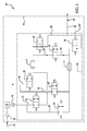
- Fig. 1 is a schematic diagram of an exemplary oxygen generating device
- Fig. 2 is an enlarged, semi-schematic front view of an example of a self-serviceable filter suitable for use in an oxygen generating device;
- Fig. 3 is a semi-schematic, cross-sectional view of the oxygen generating device taken on line 3-3 of Fig. 2 ;
- Fig. 4 is a semi-schematic, cut-away perspective view of the oxygen generating device
- Fig. 5 is a semi-schematic, cross-sectional view taken on line 5-5 of Fig. 6 ;
- Fig. 6 is a semi-schematic, exploded perspective view showing the assembly of the self-serviceable filter of Fig. 3 with a support member receivable in the oxygen generating device.
- Embodiment(s) of the device disclosed herein include a self-serviceable filter disposed between a compressor and a sieve module that advantageously removes at least a portion of the contaminant(s) from a compressed feed gas stream prior to entering the sieve module. After flowing through the filter, at least a portion, if not most, of the contaminant(s) are removed from the compressed gas stream. This substantially prevents the contaminants from flowing into and potentially degrading the operation of various components of the device such as, e.g., valves, sensors, and the sieve beds.
- Removal of at least a portion of the contaminant(s) also substantially prevents possible deactivation of the nitrogen-adsorption material disposed in the sieve beds that may otherwise occur if contacted with the contaminant(s).
- the filter used to remove the contaminant(s) from the compressed feed gas stream is also advantageously self-serviceable, thereby being relatively easily changed or serviced by the user. Additionally, the device may be substantially cleaner from removal of the contaminant(s) from the feed gas stream, thereby advantageously aiding in inhibiting the potential growth of bacteria (depending on specific materials selected for the filter member) within the device.
- FIG. 1 A non-limiting example of an oxygen generating system 10 including a self-serviceable filter 52 is schematically depicted in Fig. 1 .
- One non-limiting example of an oxygen generating system suitable for use with embodiment(s) of the method(s) and device(s) disclosed herein is depicted in Fig. 1 .
- any oxygen generating system may be suitable for use with the embodiment(s) of Figs.
- oxygen generating system(s) having fill valves (any suitable combination of 2-way, 3-way, 4-way valves, etc.), vent valves (any suitable combination of 2-way, 3-way, 4-way valves, etc.), a product tank(s), bleed orifice(s) and patient valving.
- the nitrogen-adsorption process employed by the oxygen generating system may be a pressure swing adsorption (PSA) process or a vacuum pressure swing adsorption (VPSA) process, and such processes operate in repeating adsorption/desorption cycles.
- PSA pressure swing adsorption
- VPSA vacuum pressure swing adsorption
- the oxygen generating system 10 includes a housing 11 having an inlet 13 formed therein.
- the inlet is configured to receive a feed gas from the ambient atmosphere, the feed gas including at least oxygen, nitrogen, and at least one contaminant.
- the contaminant(s) may include at least one or more solid phase components and one or more liquid phase components.
- Device/system 10 has a gross particulate intake filter (not shown) to trap dust, hair, rocks, leaves, etc. and prevent such contaminants from entering the device 10 before they can reach the compressor suction or intake port.
- the user serviceable filter 52 of the present disclosure generally filters out airborne particulates to clean the air.
- the filter 52 generally traps solid contaminants that are suspended in the gas stream.
- the filter 52 also has the ability to extract or condense water on its fibrous surface, given the tortuous flow path through the filter member and the surface tension properties of water.
- Filter 52 generally does not trap gas phase contaminants, though it may to some degree.
- the solid phase contaminants or particulates become embedded, wedged and/or trapped in the fibrous filter surface of the filter member.
- the oxygen generating device also includes at least one sieve bed.
- the oxygen generating system 10 includes first 12 and second 14 sieve beds, each in selective fluid communication with a feed gas including at least oxygen, nitrogen, and water vapor.
- the feed gas is air taken from the ambient atmosphere outside of the system 10.
- each of the first 12 and second 14 sieve beds are configured to selectively receive the feed gas during a predetermined supply period.
- the first 12 and second 14 sieve beds may receive the feed gas via first 16 and second 18 supply conduits, respectively.
- the first 16 and second 18 supply conduits are generally operatively connected to respective first 20 and second 22 supply valves (or inlet valves).
- the first 20 and second 22 supply valves are two-way valves.
- the nitrogen-adsorption process employed by the oxygen generating system 10 operates via cycles, where one of the first 12 or second 14 sieve beds vents purge gas (i.e. nitrogen-enriched gas), while the other of the first 12 or second 14 sieve beds delivers generated oxygen-enriched gas to the user.
- the functions of the respective sieve beds 12, 14 switch. Switching is accomplished by opening the respective feed gas supply valve 20, 22 while the other of the supply valves 20, 22 is closed.
- the opening and/or closing of the first 20 and second 22 supply valves may be controlled with respect to timing of opening and/or closing and/or with respect to the sequence in with the first 20 and second 22 supply valves are opened and/or closed.
- the feed gas is compressed via, e.g., a compressor 24 prior to entering the first 16 or second 18 supply conduits.
- the compressor is a scroll compressor.
- Other compressors may also be used, e.g., screw compressors, piston compressors, etc. It is to be understood, however, that compression of the feed gas may be accomplished by any suitable compression means.
- the compressed feed gas is filtered by removing at least a portion of the contaminant(s) from the compressed feed gas stream.
- filtering the compressed feed gas is accomplished using a self-serviceable filter 52 disposed between the compressor 24 and the sieve module 26.
- the filter 52 may be installed before the compressor 24 or intake port of the device 10--in such an embodiment, the filter 52 placement (e.g., as shown in phantom in Fig. 1 ) may help to maintain compressor life and potentially reduce emitted noise.
- a self-serviceable filter is a filter configured or otherwise designed in a manner sufficient for the user to change or otherwise service the filter without using tools, outside servicing help, and/or the like. Further description related to the filter 52 and the method of removing the contaminant(s) from the compressed feed gas stream is provided below in connection with Figs. 2-6 .
- the first 12 and second 14 sieve beds are each configured to separate at least most of the oxygen from the feed gas to produce the oxygen-enriched gas.
- the first 12 and second 14 sieve beds are each sieve beds 12, 14 including the nitrogen-adsorption material (e.g., zeolite, other similar suitable materials, and/or the like) configured to adsorb at least nitrogen from the feed gas.
- the sieve beds 12, 14 are operatively disposed in a housing 11 that includes sieve module 26.
- the oxygen-enriched gas generated via either the PSA or VPSA processes includes a gas product having an oxygen content ranging from about 70 vol% to about 100 vol% of the total gas product.
- the oxygen-enriched gas has an oxygen content of at least 87 vol% of the total gas product.
- a user conduit 28 having a user outlet 30 is in alternate selective fluid communication with the first and second sieve beds 12, 14.
- the user conduit 28 may be formed from any suitable material, e.g., at least partially from flexible plastic tubing.
- the user conduit 28 is configured substantially in a "Y" shape.
- the user conduit 28 may have a first conduit portion 28' and a second conduit portion 28", which are in communication with the first sieve bed 12 and the second sieve bed 14, respectively, and merge together before reaching the user outlet 30.
- the user outlet 30 may be an opening in the user conduit 28 configured to output the substantially oxygen-enriched gas for user use.
- the user outlet 30 may additionally be configured with a nasal cannula, a respiratory mask, or any other suitable device, as desired.
- the first conduit portion 28' and the second conduit portion 28" may be configured with a first user delivery valve 32 and a second user delivery valve 34, respectively.
- the first 32 and the second 34 user valves are configured as two-way valves. It is contemplated that when the oxygen-enriched gas is delivered from one of the first and second sieve beds 12, 14, to the user conduit 28, the respective one of the first 32 or second 34 user valves is open. Further, when the respective one of the first 32 or second 34 user valves is open, the respective one of the first 20 or second 22 feed gas supply valves is closed.
- the nitrogen-adsorption process selectively adsorbs at least nitrogen from the feed gas.
- the compressed feed gas is introduced into one of the first 12 or the second 14 sieve beds, thereby pressurizing the respective first 12 or second 14 sieve bed.
- Nitrogen and possibly other components present in the feed gas are adsorbed by the nitrogen-adsorption material disposed in the respective first 12 or second 14 sieve bed during an appropriate PSA/VPSA cycle. After: a predetermined amount of time; reaching a predetermined target pressure; detection of an inhalation; and/or another suitable trigger, the pressure of the respective first 12 or second 14 sieve bed is released.
- the nitrogen-enriched gas (including any other adsorbed components) is also released from the respective first 12 or second 14 sieve bed and is vented out of the system 10 through a vent port/conduit for the respective first 12 or second 14 sieve bed.
- the nitrogen-enriched gas in the first sieve bed 12 is vented through the vent conduit 36 when a first vent valve 40 is open, and the nitrogen-enriched gas in the second sieve bed 14 is vented through the vent conduit 38 when a second vent valve 42 is open. It is to be understood that venting occurs after each dynamically adjusted oxygen delivery phase and after counterfilling, each of which will be described further below.
- the gas not adsorbed by the nitrogen-adsorption material i.e., the oxygen-enriched gas
- delivery of the oxygen-enriched gas occurs during or within a predetermined amount of time after the dynamically adjusted oxygen delivery phase from the respective first 12 or second 14 sieve bed.
- the oxygen delivery system 10 may be configured to trigger an output of a predetermined volume of the oxygen-enriched gas from the sieve bed 12 upon detection of an inhalation by the user. Detection of an inhalation may be accomplished by any suitable means.
- the predetermined volume which is at least a portion of the oxygen-enriched gas produced, is output through the user conduit 28 and to the user outlet 30 during a respective dynamically adjusted oxygen delivery phase.
- the first 12 and second 14 sieve beds are also configured to transmit at least a portion of the remaining oxygen-enriched gas (i.e., the oxygen-enriched gas not delivered to the user during the delivery phase to the user outlet 30), if any, to the other of the first 12 or second 14 sieve bed. This also occurs after each respective dynamically adjusted oxygen delivery phase.
- the portion of the remaining oxygen-enriched gas may be transmitted via a counterfill flow conduit 48.
- the transmission of the remaining portion of the oxygen-enriched gas from one of the first 12 or second 14 sieve beds to the other first 12 or second 14 sieve beds may be referred to as "counterfilling."
- the counterfill flow conduit 48 may be configured with a counterfill flow valve 50.
- the counterfill flow valve 50 is a two-way valve. The counterfill flow valve 50 is opened to allow the counterfilling of the respective first 12 and second 14 sieve beds.
- the self-serviceable filter 52 includes a casing 54 surrounding a filter member 55.
- the casing 54 includes a top portion 56 having a user interface feature 58 disposed thereon or otherwise formed therein.
- the user interface feature 58 is selected and positioned on/in the top portion 56 in a manner sufficient to allow the user to access the filter 52 and to service it without using a tool or other outside servicing help.
- suitable user interface features 58 include a handle, a knob, a grip, a ring, a pin, and/or the like, and/or combinations thereof.
- the user interface feature 58 is a knurled handle.
- Top portion 56 may further include one or more position indicating members 84 configured to indicate a desired position (e.g. "installed”).
- the position indicating members 84 may be any suitable device, for example, lighting devices (e.g. LEDs) that selectively indicate a position through change of color, marker members adapted to align with corresponding marker members (not shown) on the system 10, and/or the like.
- the filter member 55 of the self-serviceable filter 52 has a filter rating ranging from about 0.01 ⁇ m to about 10 ⁇ m; and in another embodiment, has a filter rating of about 0.3 ⁇ m or smaller. In a further non-limiting example, the self-serviceable filter has an efficiency of 97% or greater. Without being bound to any theory, it is believed that a filter having a filter rating of 0.3 ⁇ m or smaller allows the filter to act as a coalescing element, thereby extracting at least a portion of the liquid phase contaminants (e.g., water), and retaining at least a portion of the solid phase components (e.g., particulates) from the compressed feed gas stream.
- the liquid phase contaminants e.g., water
- solid phase components e.g., particulates
- removal of at least these contaminants from the compressed feed gas stream prior to entering the sieve module 26 substantially prevents binding or plugging of various components of the system 10 including, but not limited to, the supply valves 20, 22, the user valves 32, 34, the vent valves 40, 42, the counterfill valve 50, the sieve beds 12, 14, and/or other various sensors, e.g., pressure sensors, temperature sensors, etc.
- the contaminant(s) may degrade or possibly deactivate the nitrogen-adsorption material disposed in the sieve beds 12, 14. This degradation and/or deactivation may, in some instances, deleteriously affect the nitrogen-adsorption process and produce an oxygen-enriched gas potentially having a lower oxygen content than desired.
- the filter 52 is disposed in the oxygen generating system 10 by disposing the filter 52 in a support 60, which is operatively disposed in a receptacle 62 formed in a desired location (e.g., a bottom side) 61 of the housing 11.
- the receptacle 62 is defined by a substantially continuous wall 64 and a base 66.
- An annular flange 68 is also formed in the housing 11, substantially integrally with the wall 64 and surrounding the receptacle 62.
- the flange 68 is configured to connect the support 60 to the receptacle 62.
- the support 60 is connected to the receptacle 62 via a fastening member 69, e.g. bolts, rivets, welds, and/or the like.
- the support 60 includes a body 70 having a continuous inner wall 72 and a base 74.
- the support 60 includes at least one connecting feature 76 configured to connect with the flange 68 (e.g., via fastening member 69), thereby operatively disposing the support 60 inside the receptacle 62.
- the support 60 further includes at least one engagement feature 78 configured to engage at least one complementary engagement feature 80 of the self-serviceable filter 52 when the filter 52 is received in the support 60.
- the engagement feature 78 is selected from a groove formed in the continuous wall 72, a fitting attached to the continuous wall 72, or a combination thereof
- the complementary engagement feature 80 is about a quarter turn cam feature formed in or attached to the filter 52.
- the quarter turn cam feature 80 is configured to engage the groove or fitting 78 so as to operatively dispose the filter 52 in the support 60.
- any desired angular revolution may be used, e.g. 135°, 180°, 270°, 360°, from about 10° to about 350°, and/or any desired angle.
- the self-serviceable filter 52 is configured to allow the user to easily remove the filter 52 from the system 10 for servicing and to either install a new filter member 55 or replace the old filter member 55 after cleaning it.
- the filter 52 is serviceable by the user without the user having to use one or more tools or to acquire outside servicing help in order to access the filter 52, to remove the filter 52, to insert a new filter 52, and combinations thereof.
- the self-serviceable filter 52 is accessible to the user by opening a door 86 (shown in phantom in Fig. 4 ) in the housing 11.
- the self-serviceable filter 52 is accessible to the user without having to remove the housing 11 or a portion thereof.
- an example of the method includes removing a previously installed filter 52 from the support 60 by turning the filter 52 about a quarter of a complete revolution (or any desired angular revolution) in a first direction, thereby disengaging the previously installed filter 52 from the support 60. This is accomplished by engaging the user interface feature 58 on the filter 52, and turning the user interface feature 58 in the first direction through a desired angular revolution.
- the user obtains a replacement (or cleaned) filter 52 and inserts the replacement/cleaned filter 52 in the support 60, e.g., by turning the replacement filter 52 in the support 60 through the desired angular revolution in a second direction opposed to the first direction. This is accomplished by engaging the user interface feature 58, and turning the user interface feature 58 in the second direction.
- connection/connected and engage/engaged are broadly defined herein to encompass a variety of divergent connection and engagement arrangements and assembly techniques. These arrangements and techniques include, but are not limited to (1) the direct connection or engagement between one component and another component with no intervening components therebetween; and (2) the connection or engagement of one component and another component with one or more components therebetween, provided that the one component being “connected to” or “engaged to” the other component is somehow operatively connected to the other component (notwithstanding the presence of one or more additional components therebetween).
Landscapes
- Chemical & Material Sciences (AREA)
- Organic Chemistry (AREA)
- Analytical Chemistry (AREA)
- Inorganic Chemistry (AREA)
- Separation Of Gases By Adsorption (AREA)
- Oxygen, Ozone, And Oxides In General (AREA)
- Separation Using Semi-Permeable Membranes (AREA)
Abstract
Description
- The present disclosure relates generally to oxygen delivery and, more particularly, to a method and device for generating an oxygen-enriched gas for a user.
- Oxygen generating devices are often used to produce an oxygen-enriched gas for a user. Oxygen generating devices typically include a gas fractionalization system configured to separate oxygen from other components (e.g., nitrogen) in a feed gas to produce the oxygen-enriched gas. The feed gas, in many instances, is air taken from the ambient environment. The gas fractionalization system, for example, may include one or more sieve beds having a nitrogen-adsorption material disposed therein and configured to adsorb at least nitrogen from the feed gas.
- The oxygen generating device may be used in a variety of different environments, especially if the device is portable. As such, these devices may be subjected to relatively harsh contaminants present in the feed gas stream. Such contaminants may include, e.g., water vapor, cigarette smoke, spores, bacteria, and/or small particulates that may potentially degrade the operation of various components of the device. Further, these contaminants may contaminate or otherwise potentially compromise the adsorption/desorption capabilities of the nitrogen-adsorption material.
- An oxygen generating device includes: a housing; an inlet formed in the housing and configured to receive a feed gas including oxygen, nitrogen, and at least one contaminant; a compressor; a sieve module including at least one sieve bed configured to generate an oxygen-enriched gas for a user by adsorbing nitrogen from the feed gas via a nitrogen-adsorption process; and a self-serviceable filter disposed in the oxygen generating system between the compressing means and the sieve module, the self serviceable filter being configured to remove at least a portion of the contaminant(s) from the feed gas.
- Features and advantages of the present disclosure will become apparent by reference to the following detailed description and drawings, in which like reference numerals correspond to similar, though perhaps not identical components. For the sake of brevity, reference numerals or features having a previously described function may or may not necessarily be described in connection with other drawings in which they appear.
-
Fig. 1 is a schematic diagram of an exemplary oxygen generating device; -
Fig. 2 is an enlarged, semi-schematic front view of an example of a self-serviceable filter suitable for use in an oxygen generating device; -
Fig. 3 is a semi-schematic, cross-sectional view of the oxygen generating device taken on line 3-3 ofFig. 2 ; -
Fig. 4 is a semi-schematic, cut-away perspective view of the oxygen generating device; -
Fig. 5 is a semi-schematic, cross-sectional view taken on line 5-5 ofFig. 6 ; and -
Fig. 6 is a semi-schematic, exploded perspective view showing the assembly of the self-serviceable filter ofFig. 3 with a support member receivable in the oxygen generating device. - Embodiment(s) of the device disclosed herein include a self-serviceable filter disposed between a compressor and a sieve module that advantageously removes at least a portion of the contaminant(s) from a compressed feed gas stream prior to entering the sieve module. After flowing through the filter, at least a portion, if not most, of the contaminant(s) are removed from the compressed gas stream. This substantially prevents the contaminants from flowing into and potentially degrading the operation of various components of the device such as, e.g., valves, sensors, and the sieve beds. Removal of at least a portion of the contaminant(s) also substantially prevents possible deactivation of the nitrogen-adsorption material disposed in the sieve beds that may otherwise occur if contacted with the contaminant(s). The filter used to remove the contaminant(s) from the compressed feed gas stream is also advantageously self-serviceable, thereby being relatively easily changed or serviced by the user. Additionally, the device may be substantially cleaner from removal of the contaminant(s) from the feed gas stream, thereby advantageously aiding in inhibiting the potential growth of bacteria (depending on specific materials selected for the filter member) within the device.
- A non-limiting example of an
oxygen generating system 10 including a self-serviceable filter 52 is schematically depicted inFig. 1 . One non-limiting example of an oxygen generating system suitable for use with embodiment(s) of the method(s) and device(s) disclosed herein is depicted inFig. 1 . However, it is to be understood that any oxygen generating system may be suitable for use with the embodiment(s) ofFigs. 2-6 , various examples of which (not shown) are oxygen generating system(s) having fill valves (any suitable combination of 2-way, 3-way, 4-way valves, etc.), vent valves (any suitable combination of 2-way, 3-way, 4-way valves, etc.), a product tank(s), bleed orifice(s) and patient valving. - It is to be understood that the nitrogen-adsorption process employed by the oxygen generating system may be a pressure swing adsorption (PSA) process or a vacuum pressure swing adsorption (VPSA) process, and such processes operate in repeating adsorption/desorption cycles.
- The
oxygen generating system 10 includes ahousing 11 having aninlet 13 formed therein. The inlet is configured to receive a feed gas from the ambient atmosphere, the feed gas including at least oxygen, nitrogen, and at least one contaminant. The contaminant(s) may include at least one or more solid phase components and one or more liquid phase components. Device/system 10 has a gross particulate intake filter (not shown) to trap dust, hair, rocks, leaves, etc. and prevent such contaminants from entering thedevice 10 before they can reach the compressor suction or intake port. The userserviceable filter 52 of the present disclosure generally filters out airborne particulates to clean the air. Thefilter 52 generally traps solid contaminants that are suspended in the gas stream. Thefilter 52 also has the ability to extract or condense water on its fibrous surface, given the tortuous flow path through the filter member and the surface tension properties of water.Filter 52 generally does not trap gas phase contaminants, though it may to some degree. The solid phase contaminants or particulates become embedded, wedged and/or trapped in the fibrous filter surface of the filter member. - The oxygen generating device also includes at least one sieve bed. In the example shown in
Fig. 1 , theoxygen generating system 10 includes first 12 and second 14 sieve beds, each in selective fluid communication with a feed gas including at least oxygen, nitrogen, and water vapor. In a non-limiting example, the feed gas is air taken from the ambient atmosphere outside of thesystem 10. In an embodiment, each of the first 12 and second 14 sieve beds are configured to selectively receive the feed gas during a predetermined supply period. The first 12 and second 14 sieve beds may receive the feed gas via first 16 and second 18 supply conduits, respectively. - The first 16 and second 18 supply conduits are generally operatively connected to respective first 20 and second 22 supply valves (or inlet valves). In a non-limiting example, the first 20 and second 22 supply valves are two-way valves. As provided above, the nitrogen-adsorption process employed by the oxygen generating
system 10 operates via cycles, where one of the first 12 or second 14 sieve beds vents purge gas (i.e. nitrogen-enriched gas), while the other of the first 12 or second 14 sieve beds delivers generated oxygen-enriched gas to the user. During the next cycle, the functions of the respective sieve beds 12, 14 switch. Switching is accomplished by opening the respective feedgas supply valve supply valves - In an embodiment, the feed gas is compressed via, e.g., a
compressor 24 prior to entering the first 16 or second 18 supply conduits. In a non-limiting example, the compressor is a scroll compressor. Other compressors may also be used, e.g., screw compressors, piston compressors, etc. It is to be understood, however, that compression of the feed gas may be accomplished by any suitable compression means. - After compression, the compressed feed gas is filtered by removing at least a portion of the contaminant(s) from the compressed feed gas stream. In an embodiment, filtering the compressed feed gas is accomplished using a self-
serviceable filter 52 disposed between thecompressor 24 and thesieve module 26. In alternate embodiments, thefilter 52 may be installed before thecompressor 24 or intake port of thedevice 10--in such an embodiment, thefilter 52 placement (e.g., as shown in phantom inFig. 1 ) may help to maintain compressor life and potentially reduce emitted noise. As referred to herein, a "self-serviceable filter" is a filter configured or otherwise designed in a manner sufficient for the user to change or otherwise service the filter without using tools, outside servicing help, and/or the like. Further description related to thefilter 52 and the method of removing the contaminant(s) from the compressed feed gas stream is provided below in connection withFigs. 2-6 . - After receiving the filtered, compressed feed gas, the first 12 and second 14 sieve beds are each configured to separate at least most of the oxygen from the feed gas to produce the oxygen-enriched gas. In an embodiment, the first 12 and second 14 sieve beds are each
sieve beds Fig. 1 , thesieve beds housing 11 that includessieve module 26. - In a non-limiting example, the oxygen-enriched gas generated via either the PSA or VPSA processes includes a gas product having an oxygen content ranging from about 70 vol% to about 100 vol% of the total gas product. In another non-limiting example, the oxygen-enriched gas has an oxygen content of at least 87 vol% of the total gas product.
- A
user conduit 28 having auser outlet 30 is in alternate selective fluid communication with the first andsecond sieve beds user conduit 28 may be formed from any suitable material, e.g., at least partially from flexible plastic tubing. In an embodiment, theuser conduit 28 is configured substantially in a "Y" shape. As such, theuser conduit 28 may have a first conduit portion 28' and asecond conduit portion 28", which are in communication with thefirst sieve bed 12 and thesecond sieve bed 14, respectively, and merge together before reaching theuser outlet 30. Theuser outlet 30 may be an opening in theuser conduit 28 configured to output the substantially oxygen-enriched gas for user use. Theuser outlet 30 may additionally be configured with a nasal cannula, a respiratory mask, or any other suitable device, as desired. - The first conduit portion 28' and the
second conduit portion 28" may be configured with a firstuser delivery valve 32 and a seconduser delivery valve 34, respectively. In an embodiment, the first 32 and the second 34 user valves are configured as two-way valves. It is contemplated that when the oxygen-enriched gas is delivered from one of the first andsecond sieve beds user conduit 28, the respective one of the first 32 or second 34 user valves is open. Further, when the respective one of the first 32 or second 34 user valves is open, the respective one of the first 20 or second 22 feed gas supply valves is closed. - The nitrogen-adsorption process selectively adsorbs at least nitrogen from the feed gas. Generally, the compressed feed gas is introduced into one of the first 12 or the second 14 sieve beds, thereby pressurizing the respective first 12 or second 14 sieve bed. Nitrogen and possibly other components present in the feed gas are adsorbed by the nitrogen-adsorption material disposed in the respective first 12 or second 14 sieve bed during an appropriate PSA/VPSA cycle. After: a predetermined amount of time; reaching a predetermined target pressure; detection of an inhalation; and/or another suitable trigger, the pressure of the respective first 12 or second 14 sieve bed is released. At this point, the nitrogen-enriched gas (including any other adsorbed components) is also released from the respective first 12 or second 14 sieve bed and is vented out of the
system 10 through a vent port/conduit for the respective first 12 or second 14 sieve bed. As shown inFig. 1 , the nitrogen-enriched gas in thefirst sieve bed 12 is vented through thevent conduit 36 when afirst vent valve 40 is open, and the nitrogen-enriched gas in thesecond sieve bed 14 is vented through thevent conduit 38 when asecond vent valve 42 is open. It is to be understood that venting occurs after each dynamically adjusted oxygen delivery phase and after counterfilling, each of which will be described further below. The gas not adsorbed by the nitrogen-adsorption material (i.e., the oxygen-enriched gas) is delivered to the user through theuser outlet 30. - In an embodiment, delivery of the oxygen-enriched gas occurs during or within a predetermined amount of time after the dynamically adjusted oxygen delivery phase from the respective first 12 or second 14 sieve bed. For example, the
oxygen delivery system 10 may be configured to trigger an output of a predetermined volume of the oxygen-enriched gas from thesieve bed 12 upon detection of an inhalation by the user. Detection of an inhalation may be accomplished by any suitable means. The predetermined volume, which is at least a portion of the oxygen-enriched gas produced, is output through theuser conduit 28 and to theuser outlet 30 during a respective dynamically adjusted oxygen delivery phase. - The first 12 and second 14 sieve beds are also configured to transmit at least a portion of the remaining oxygen-enriched gas (i.e., the oxygen-enriched gas not delivered to the user during the delivery phase to the user outlet 30), if any, to the other of the first 12 or second 14 sieve bed. This also occurs after each respective dynamically adjusted oxygen delivery phase. The portion of the remaining oxygen-enriched gas may be transmitted via a
counterfill flow conduit 48. The transmission of the remaining portion of the oxygen-enriched gas from one of the first 12 or second 14 sieve beds to the other first 12 or second 14 sieve beds may be referred to as "counterfilling." - As shown in
Fig. 1 , thecounterfill flow conduit 48 may be configured with acounterfill flow valve 50. In a non-limiting example, thecounterfill flow valve 50 is a two-way valve. The counterfill flowvalve 50 is opened to allow the counterfilling of the respective first 12 and second 14 sieve beds. - With reference now to
Figs. 2, 3 and6 , the self-serviceable filter 52 includes acasing 54 surrounding afilter member 55. Thecasing 54 includes atop portion 56 having auser interface feature 58 disposed thereon or otherwise formed therein. Theuser interface feature 58 is selected and positioned on/in thetop portion 56 in a manner sufficient to allow the user to access thefilter 52 and to service it without using a tool or other outside servicing help. Non-limiting examples of suitable user interface features 58 include a handle, a knob, a grip, a ring, a pin, and/or the like, and/or combinations thereof. In the embodiment depicted inFigs. 2 and 3 , theuser interface feature 58 is a knurled handle. -
Top portion 56 may further include one or moreposition indicating members 84 configured to indicate a desired position (e.g. "installed"). Theposition indicating members 84 may be any suitable device, for example, lighting devices (e.g. LEDs) that selectively indicate a position through change of color, marker members adapted to align with corresponding marker members (not shown) on thesystem 10, and/or the like. - In a non-limiting example, the
filter member 55 of the self-serviceable filter 52 has a filter rating ranging from about 0.01 µm to about 10 µm; and in another embodiment, has a filter rating of about 0.3 µm or smaller. In a further non-limiting example, the self-serviceable filter has an efficiency of 97% or greater. Without being bound to any theory, it is believed that a filter having a filter rating of 0.3 µm or smaller allows the filter to act as a coalescing element, thereby extracting at least a portion of the liquid phase contaminants (e.g., water), and retaining at least a portion of the solid phase components (e.g., particulates) from the compressed feed gas stream. It is further believed that removal of at least these contaminants from the compressed feed gas stream prior to entering thesieve module 26 substantially prevents binding or plugging of various components of thesystem 10 including, but not limited to, thesupply valves user valves vent valves counterfill valve 50, thesieve beds sieve beds - With reference now to
Fig. 3-5 , thefilter 52 is disposed in theoxygen generating system 10 by disposing thefilter 52 in asupport 60, which is operatively disposed in areceptacle 62 formed in a desired location (e.g., a bottom side) 61 of thehousing 11. As shown inFigs. 4 and5 , thereceptacle 62 is defined by a substantiallycontinuous wall 64 and abase 66. Anannular flange 68 is also formed in thehousing 11, substantially integrally with thewall 64 and surrounding thereceptacle 62. Theflange 68 is configured to connect thesupport 60 to thereceptacle 62. In a non-limiting example, thesupport 60 is connected to thereceptacle 62 via afastening member 69, e.g. bolts, rivets, welds, and/or the like. - As shown in
Figs. 3 and5-6 , thesupport 60 includes abody 70 having a continuousinner wall 72 and abase 74. Thesupport 60 includes at least one connectingfeature 76 configured to connect with the flange 68 (e.g., via fastening member 69), thereby operatively disposing thesupport 60 inside thereceptacle 62. - The
support 60 further includes at least oneengagement feature 78 configured to engage at least onecomplementary engagement feature 80 of the self-serviceable filter 52 when thefilter 52 is received in thesupport 60. In a non-limiting example, theengagement feature 78 is selected from a groove formed in thecontinuous wall 72, a fitting attached to thecontinuous wall 72, or a combination thereof, and thecomplementary engagement feature 80 is about a quarter turn cam feature formed in or attached to thefilter 52. As shown inFig. 6 , the quarterturn cam feature 80 is configured to engage the groove or fitting 78 so as to operatively dispose thefilter 52 in thesupport 60. Although about a quarter turn is recited above as an example, it is to be understood that any desired angular revolution may be used, e.g. 135°, 180°, 270°, 360°, from about 10° to about 350°, and/or any desired angle. - As provided above, the self-
serviceable filter 52 is configured to allow the user to easily remove thefilter 52 from thesystem 10 for servicing and to either install anew filter member 55 or replace theold filter member 55 after cleaning it. As provided above, thefilter 52 is serviceable by the user without the user having to use one or more tools or to acquire outside servicing help in order to access thefilter 52, to remove thefilter 52, to insert anew filter 52, and combinations thereof. In order to accomplish this, the self-serviceable filter 52 is accessible to the user by opening a door 86 (shown in phantom inFig. 4 ) in thehousing 11. In another embodiment, the self-serviceable filter 52 is accessible to the user without having to remove thehousing 11 or a portion thereof. - To service the self-
serviceable filter 52, an example of the method includes removing a previously installedfilter 52 from thesupport 60 by turning thefilter 52 about a quarter of a complete revolution (or any desired angular revolution) in a first direction, thereby disengaging the previously installedfilter 52 from thesupport 60. This is accomplished by engaging theuser interface feature 58 on thefilter 52, and turning theuser interface feature 58 in the first direction through a desired angular revolution. - In this example, once the previously installed
filter 52 is removed from thesupport 60, the user obtains a replacement (or cleaned)filter 52 and inserts the replacement/cleanedfilter 52 in thesupport 60, e.g., by turning thereplacement filter 52 in thesupport 60 through the desired angular revolution in a second direction opposed to the first direction. This is accomplished by engaging theuser interface feature 58, and turning theuser interface feature 58 in the second direction. - It is to be understood that the terms "connect/connected" and "engage/engaged" are broadly defined herein to encompass a variety of divergent connection and engagement arrangements and assembly techniques. These arrangements and techniques include, but are not limited to (1) the direct connection or engagement between one component and another component with no intervening components therebetween; and (2) the connection or engagement of one component and another component with one or more components therebetween, provided that the one component being "connected to" or "engaged to" the other component is somehow operatively connected to the other component (notwithstanding the presence of one or more additional components therebetween).
- While several embodiments have been described in detail, it will be apparent to those skilled in the art that the disclosed embodiments may be modified and/or other embodiments may be possible. Therefore, the foregoing description is to be considered exemplary rather than limiting.
Claims (13)
- An oxygen generating device, comprising:a housing;an inlet formed in the housing and configured to receive a feed gas including oxygen, nitrogen, and at least one contaminant; a compressor;a sieve module including at least one sieve bed configured to generate an oxygen-enriched gas for a user by adsorbing nitrogen from the compressed feed gas via a nitrogen-adsorption process; anda self-serviceable filter disposed in the oxygen generating system between the compressor and the sieve module, the self-serviceable filter being configured to remove at least a portion of the at least one contaminant from the compressed feed gas.
- The oxygen generating device as defined in claim 1 wherein the self-serviceable filter has a filter rating of about 0.3 µm or smaller.
- The oxygen generating device as defined in claim 1 wherein the at least one contaminant includes at least one liquid phase component and at least one solid phase component, and wherein the self-serviceable filter is further configured to extract at least a portion of the at least one liquid phase component from the feed gas and to retain at least a portion of the at least one solid phase component from the feed gas.
- The oxygen generating device as defined in claim 1 wherein the self-serviceable filter is disposed in the oxygen generating device in a manner sufficient to allow a user to access the filter: by opening a door in the housing; or without removing at least a portion of the housing.
- The oxygen generating device as defined in claim 4 wherein the housing includes a receptacle formed therein, the receptacle being defined by a substantially continuous wall and a base.
- The oxygen generating device as defined in claim 5, further comprising a support configured to be disposed in the receptacle, and wherein the support is further configured to receive the self-serviceable filter.
- The oxygen generating device as defined in claim 6 wherein the support includes at least one engagement feature configured to engage at least one complementary engagement feature of the self-serviceable filter when the self-serviceable filter is received in the support.
- The oxygen generating device as defined in claim 7 wherein the engagement feature of the support is selected from a groove formed in the substantially continuous wall, a fitting attached to the substantially continuous wall, or a combination thereof.
- The oxygen generating device as defined in claim 8 wherein the at least one complementary engagement feature of the self-serviceable filter is a quarter turn cam feature formed therein or attached thereto, and wherein the quarter turn cam feature is configured to engage at least one of the groove or the fitting.
- The oxygen generating device as defined in claim 1 wherein the self-serviceable filter includes a user interface feature selected from a handle, a knob, a grip, a ring, a pin, and combinations thereof.
- A method of generating an oxygen-enriched gas for a user via an oxygen generating device, the oxygen generating device including a housing including a sieve module disposed therein, wherein the sieve module includes at least one sieve bed having a nitrogen-adsorbing material disposed therein and configured to adsorb nitrogen from a feed gas introduced into the at least one sieve bed, the feed gas including at least nitrogen, oxygen, and at least one contaminant, the method comprising:introducing the feed gas into the oxygen generating device via an inlet;compressing the feed gas via a compressor;filtering the compressed feed gas by removing the at least one contaminant from the compressed feed gas via a self-serviceable filter, the self-serviceable filter being disposed in the oxygen generating device between the compressor and the sieve module;introducing the filtered feed gas into the sieve module; andgenerating the oxygen-enriched gas from the filtered feed gas.
- The method as defined in claim 11 wherein the self-serviceable filter is disposed in the oxygen generating device in a manner sufficient to allow a user to access the filter: by opening a door in the housing; without removing at least a portion of the housing; or combinations thereof.
- The method as defined in claim 11 wherein the at least one contaminant includes at least one liquid phase component and at least one solid phase component, and wherein the method further comprises:extracting at least a portion of the at least one liquid phase component from the compressed feed gas via the self-serviceable filter; andretaining at least a portion of the at least one solid phase component from the compressed feed gas in the self-serviceable filter.
Applications Claiming Priority (1)
| Application Number | Priority Date | Filing Date | Title |
|---|---|---|---|
| US12/070,917 US20090211443A1 (en) | 2008-02-21 | 2008-02-21 | Self-serviceable filter for an oxygen generating device |
Publications (2)
| Publication Number | Publication Date |
|---|---|
| EP2093189A2 true EP2093189A2 (en) | 2009-08-26 |
| EP2093189A3 EP2093189A3 (en) | 2009-10-14 |
Family
ID=40765621
Family Applications (1)
| Application Number | Title | Priority Date | Filing Date |
|---|---|---|---|
| EP09152323A Withdrawn EP2093189A3 (en) | 2008-02-21 | 2009-02-06 | Self-serviceable filter for an oxygengenerating device |
Country Status (2)
| Country | Link |
|---|---|
| US (1) | US20090211443A1 (en) |
| EP (1) | EP2093189A3 (en) |
Families Citing this family (1)
| Publication number | Priority date | Publication date | Assignee | Title |
|---|---|---|---|---|
| US8075676B2 (en) * | 2008-02-22 | 2011-12-13 | Oxus America, Inc. | Damping apparatus for scroll compressors for oxygen-generating systems |
Family Cites Families (100)
| Publication number | Priority date | Publication date | Assignee | Title |
|---|---|---|---|---|
| US3675649A (en) * | 1970-08-21 | 1972-07-11 | Westland Aircraft Ltd | Electronically controlled oxygen regulators |
| US4182599A (en) * | 1973-10-02 | 1980-01-08 | Chemetron Corporation | Volume-rate respirator system and method |
| US3957463A (en) * | 1973-12-12 | 1976-05-18 | Air Products And Chemicals, Inc. | Oxygen enrichment process |
| US4013429A (en) * | 1975-06-04 | 1977-03-22 | Air Products And Chemicals, Inc. | Fractionation of air by adsorption |
| US4066423A (en) * | 1976-09-27 | 1978-01-03 | Ht Management Company | Adsorption-absorption vapor recovery system |
| US4342573A (en) * | 1979-10-12 | 1982-08-03 | Greene & Kellogg, Incorporated | Compact oxygen concentrator |
| GB2086258A (en) * | 1980-10-30 | 1982-05-12 | Boc Ltd | Process and apparatus for separation of a gaseous mixture |
| US4378982A (en) * | 1981-08-28 | 1983-04-05 | Greene & Kellogg, Inc. | Compact oxygen concentrator |
| US4376640A (en) * | 1981-12-10 | 1983-03-15 | Calgon Corporation | Repressurization of pressure swing adsorption system |
| US4648888A (en) * | 1982-07-09 | 1987-03-10 | Hudson Oxygen Therapy Sales Co. | Oxygen concentrator |
| US4516424A (en) * | 1982-07-09 | 1985-05-14 | Hudson Oxygen Therapy Sales Company | Oxygen concentrator monitor and regulation assembly |
| US4449990A (en) * | 1982-09-10 | 1984-05-22 | Invacare Respiratory Corp. | Method and apparatus for fractioning oxygen |
| US4983190A (en) * | 1985-05-21 | 1991-01-08 | Pall Corporation | Pressure-swing adsorption system and method for NBC collective protection |
| US4759782A (en) * | 1985-07-05 | 1988-07-26 | Pall Corporation | Coalescing filter for removal of liquid aerosols from gaseous streams |
| US4816039A (en) * | 1986-02-24 | 1989-03-28 | The Boc Group, Inc. | PSA multicomponent separation utilizing tank equalization |
| US4758252A (en) * | 1987-06-26 | 1988-07-19 | The Boc Group, Inc. | Hydrostatic method employing PSA vent gas pressure for vacuum regeneration |
| US4810265A (en) * | 1987-12-29 | 1989-03-07 | Union Carbide Corporation | Pressure swing adsorption process for gas separation |
| JP2683806B2 (en) * | 1988-03-17 | 1997-12-03 | 住友精化株式会社 | Concentrated oxygen recovery method |
| US5161525A (en) * | 1990-05-11 | 1992-11-10 | Puritan-Bennett Corporation | System and method for flow triggering of pressure supported ventilation |
| US5228888A (en) * | 1990-03-23 | 1993-07-20 | The Boc Group, Inc. | Economical air separator |
| DE69124276T2 (en) * | 1990-03-29 | 1997-05-07 | Boc Group Inc | Process for the production of an oxygen enriched product stream |
| US5099837A (en) * | 1990-09-28 | 1992-03-31 | Russel Sr Larry L | Inhalation-based control of medical gas |
| US5203887A (en) * | 1991-12-11 | 1993-04-20 | Praxair Technology, Inc. | Adsorbent beds for pressure swing adsorption operations |
| CA2109017A1 (en) * | 1992-12-16 | 1994-06-17 | Donald M. Smith | Method and apparatus for the intermittent delivery of oxygen therapy to a person |
| US5429664A (en) * | 1993-02-22 | 1995-07-04 | Air Products And Chemicals, Inc. | Pressure swing absorption with recycle of void space gas |
| US5294247A (en) * | 1993-02-26 | 1994-03-15 | Air Products And Chemicals, Inc. | Adsorption process to recover hydrogen from low pressure feeds |
| US5429666A (en) * | 1994-02-03 | 1995-07-04 | Air Products And Chemicals, Inc. | VSA adsorption process with continuous operation |
| US5518526A (en) * | 1994-10-07 | 1996-05-21 | Praxair Technology, Inc. | Pressure swing adsorption process |
| US5531807A (en) * | 1994-11-30 | 1996-07-02 | Airsep Corporation | Apparatus and method for supplying oxygen to passengers on board aircraft |
| US5549720A (en) * | 1994-12-19 | 1996-08-27 | Nellcor Puritan-Bennett Incorporated | Filter |
| US5704964A (en) * | 1994-12-27 | 1998-01-06 | Nippon Sanso Corporation | Pressure swing adsorption process |
| JP3309197B2 (en) * | 1995-03-02 | 2002-07-29 | 住友精化株式会社 | Recovery method of concentrated oxygen |
| US5706801A (en) * | 1995-07-28 | 1998-01-13 | Caire Inc. | Sensing and communications system for use with oxygen delivery apparatus |
| US5603315A (en) * | 1995-08-14 | 1997-02-18 | Reliable Engineering | Multiple mode oxygen delivery system |
| EP0760247A3 (en) * | 1995-08-30 | 1997-04-23 | Devilbiss Health Care Inc | Oxygen concentrator monitoring system |
| DE19680906D2 (en) * | 1995-10-23 | 1998-10-29 | Huf Hans Joachim Dr | Procedure for the supply of subjects with an increased oxygen supply |
| US5632268A (en) * | 1996-02-02 | 1997-05-27 | Ellis; Donald L. | Multiple purpose fixed or portable oxygen delivery system |
| US5755224A (en) * | 1996-05-23 | 1998-05-26 | Sunrise Medical Hhg Inc. | Cylinder-mounted oxygen management device |
| US5917135A (en) * | 1996-06-14 | 1999-06-29 | Invacare Corporation | Gas concentration sensor and control for oxygen concentrator utilizing gas concentration sensor |
| US5906672A (en) * | 1996-06-14 | 1999-05-25 | Invacare Corporation | Closed-loop feedback control for oxygen concentrator |
| US5766310A (en) * | 1996-07-19 | 1998-06-16 | Litton Systems Incorporated | Single stage secondary high purity oxygen concentrator |
| US5865174A (en) * | 1996-10-29 | 1999-02-02 | The Scott Fetzer Company | Supplemental oxygen delivery apparatus and method |
| US5890490A (en) * | 1996-11-29 | 1999-04-06 | Aylsworth; Alonzo C. | Therapeutic gas flow monitoring system |
| ATE261757T1 (en) * | 1996-12-11 | 2004-04-15 | Sgi Prozess Technik Gmbh | METHOD FOR OPERATING A PRESSURE EXCHANGE SYSTEM FOR OBTAINING OXYGEN FROM THE AIR |
| US5912426A (en) * | 1997-01-30 | 1999-06-15 | Praxair Technology, Inc. | System for energy recovery in a vacuum pressure swing adsorption apparatus |
| DE602004010465T2 (en) * | 1997-01-31 | 2008-03-13 | RIC Investments, Inc., Wilmington | Pressure swing absorption device with multi-chamber container |
| US5858062A (en) * | 1997-02-10 | 1999-01-12 | Litton Systems, Inc. | Oxygen concentrator |
| US5779767A (en) * | 1997-03-07 | 1998-07-14 | Air Products And Chemicals, Inc. | Use of zeolites and alumina in adsorption processes |
| US5871564A (en) * | 1997-06-16 | 1999-02-16 | Airsep Corp | Pressure swing adsorption apparatus |
| US6371114B1 (en) * | 1998-07-24 | 2002-04-16 | Minnesota Innovative Technologies & Instruments Corporation | Control device for supplying supplemental respiratory oxygen |
| KR19990028153A (en) * | 1997-09-30 | 1999-04-15 | 정휘동 | Portable PS Oxygen Generator |
| US7204249B1 (en) * | 1997-10-01 | 2007-04-17 | Invcare Corporation | Oxygen conserving device utilizing a radial multi-stage compressor for high-pressure mobile storage |
| US6010555A (en) * | 1997-11-04 | 2000-01-04 | Praxair Technology, Inc. | Vacuum pressure swing adsorption system and method |
| US20050121033A1 (en) * | 1998-02-25 | 2005-06-09 | Ric Investments, Llc. | Respiratory monitoring during gas delivery |
| US6045603A (en) * | 1998-08-21 | 2000-04-04 | The Boc Group, Inc. | Two phase pressure swing adsorption process |
| US6220244B1 (en) * | 1998-09-15 | 2001-04-24 | Mclaughlin Patrick L. | Conserving device for use in oxygen delivery and therapy |
| AU1210500A (en) * | 1998-10-21 | 2000-05-08 | Airsep Corporation | Combined oxygen regulator and conservation device |
| US6446630B1 (en) * | 1999-02-11 | 2002-09-10 | Sunrise Medical Hhg Inc | Cylinder filling medical oxygen concentrator |
| DE60027493T2 (en) * | 1999-02-19 | 2006-12-07 | Teijin Ltd. | Apparatus for producing oxygen-enriched gas from air |
| US6536431B1 (en) * | 1999-04-26 | 2003-03-25 | Oxygen Leisure Products Limited | Oxygen dispenser |
| US6346139B1 (en) * | 1999-05-12 | 2002-02-12 | Respironics, Inc. | Total delivery oxygen concentration system |
| US6348082B1 (en) * | 1999-05-14 | 2002-02-19 | Respironics, Inc. | Gas fractionalization system and associated method |
| US6245127B1 (en) * | 1999-05-27 | 2001-06-12 | Praxair Technology, Inc. | Pressure swing adsorption process and apparatus |
| US6311719B1 (en) * | 1999-08-10 | 2001-11-06 | Sequal Technologies, Inc. | Rotary valve assembly for pressure swing adsorption system |
| US7250073B2 (en) * | 1999-12-09 | 2007-07-31 | Questair Technologies, Inc. | Life support oxygen concentrator |
| US6394089B1 (en) * | 2000-01-18 | 2002-05-28 | Northrop Grumman Corporation | Patient ventilator oxygen concentration system |
| US6558451B2 (en) * | 2000-05-10 | 2003-05-06 | Airsep Corporation | Multiple bed pressure swing adsorption method and apparatus |
| FR2809329B1 (en) * | 2000-05-25 | 2002-08-16 | Air Liquide | PORTABLE OXYGEN CONCENTRATOR |
| US6524370B2 (en) * | 2000-07-28 | 2003-02-25 | The Boc Group, Inc. | Oxygen production |
| DE60115458T2 (en) * | 2000-08-02 | 2006-08-17 | Wearair Oxygen Inc., Kelowna | MINIATURIZED PORTABLE OXYGEN CONCENTRATOR |
| US6691702B2 (en) * | 2000-08-03 | 2004-02-17 | Sequal Technologies, Inc. | Portable oxygen concentration system and method of using the same |
| JP4246365B2 (en) * | 2000-09-21 | 2009-04-02 | 日本特殊陶業株式会社 | Oxygen concentrator, its control device, and recording medium |
| JP2002085568A (en) * | 2000-09-21 | 2002-03-26 | Ngk Spark Plug Co Ltd | Oxygen supply device, its control device, and recording medium |
| JP4293581B2 (en) * | 2000-09-21 | 2009-07-08 | 日本特殊陶業株式会社 | Oxygen concentrator, control device, and recording medium |
| US6622726B1 (en) * | 2000-10-17 | 2003-09-23 | Newport Medical Instruments, Inc. | Breathing apparatus and method |
| US6511526B2 (en) * | 2001-01-12 | 2003-01-28 | Vbox, Incorporated | Pressure swing adsorption gas separation method and apparatus |
| US6675798B1 (en) * | 2001-01-18 | 2004-01-13 | Automed - Automatic Dosage Systems, Ltd. | Automatically regulating oxygen flow to a patient |
| US6551384B1 (en) * | 2001-07-05 | 2003-04-22 | Praxair Technology, Inc. | Medical oxygen concentrator |
| US20030051730A1 (en) * | 2001-09-14 | 2003-03-20 | Ross Thuener | Demand supply oxygen delivery system |
| KR100532206B1 (en) * | 2001-10-22 | 2005-11-30 | 주식회사 옥서스 | Concentrated unit for oxygen concentration apparatus |
| DE10152359A1 (en) * | 2001-10-24 | 2003-05-08 | Linde Ag | Adsorber station used in the removal of water and carbon dioxide from feed air in a low-temperature air separation plant comprises adsorbers and ring lines with gas supply and drain valves, and regeneration gas supply and drain valves |
| US20030140924A1 (en) * | 2001-11-06 | 2003-07-31 | Aylsworth Alonzo C. | Therapeutic gas conserver and control |
| JP4473580B2 (en) * | 2002-01-31 | 2010-06-02 | エアーセップ・コーポレーション | Portable oxygen concentrator |
| US6702880B2 (en) * | 2002-05-17 | 2004-03-09 | Porous Media Corporation | Inlet silencer/filter for an oxygen concentrator |
| US6712877B2 (en) * | 2002-08-27 | 2004-03-30 | Litton Systems, Inc. | Oxygen concentrator system |
| KR200337953Y1 (en) * | 2002-10-18 | 2004-01-07 | 마츠시타 덴끼 산교 가부시키가이샤 | Oxygen enrichment apparatus |
| JP2004261223A (en) * | 2003-02-14 | 2004-09-24 | Teijin Ltd | Medical oxygen concentrator |
| JP4301452B2 (en) * | 2003-02-18 | 2009-07-22 | サンビオー2 カンパニー,リミティド | Gas concentration method and apparatus |
| US7188621B2 (en) * | 2003-08-04 | 2007-03-13 | Pulmonetic Systems, Inc. | Portable ventilator system |
| US6878186B2 (en) * | 2003-09-09 | 2005-04-12 | David Lloyd Neary | Pure vacuum swing adsorption system and apparatus |
| EP1677895A2 (en) * | 2003-10-07 | 2006-07-12 | Inogen, Inc. | Portable gas fractionalization system |
| US20050072426A1 (en) * | 2003-10-07 | 2005-04-07 | Deane Geoffrey Frank | Portable gas fractionalization system |
| US7066985B2 (en) * | 2003-10-07 | 2006-06-27 | Inogen, Inc. | Portable gas fractionalization system |
| US20050072423A1 (en) * | 2003-10-07 | 2005-04-07 | Deane Geoffrey Frank | Portable gas fractionalization system |
| US7552731B2 (en) * | 2003-11-14 | 2009-06-30 | Remcore, Inc. | Remote control gas regulation system |
| US7056372B2 (en) * | 2004-01-13 | 2006-06-06 | Ming Hui Cheng | Air treatment device having various selections |
| US7171963B2 (en) * | 2005-02-09 | 2007-02-06 | Vbox, Incorporated | Product pump for an oxygen concentrator |
| US20060242934A1 (en) * | 2005-04-27 | 2006-11-02 | Midwest Air Technologies, Inc. | Air filter assembly |
| US20070289445A1 (en) * | 2006-06-15 | 2007-12-20 | Mei Hua | Compact and efficient pressure swing oxygen concentrator |
| US7763100B2 (en) * | 2006-07-06 | 2010-07-27 | Praxair Technology, Inc. | Vacuum pressure swing adsorption process and enhanced oxygen recovery |
-
2008
- 2008-02-21 US US12/070,917 patent/US20090211443A1/en not_active Abandoned
-
2009
- 2009-02-06 EP EP09152323A patent/EP2093189A3/en not_active Withdrawn
Also Published As
| Publication number | Publication date |
|---|---|
| EP2093189A3 (en) | 2009-10-14 |
| US20090211443A1 (en) | 2009-08-27 |
Similar Documents
| Publication | Publication Date | Title |
|---|---|---|
| KR100495974B1 (en) | Air purification device with oxygen-supplying function, for automobiles | |
| EP2059325B1 (en) | Oxygen concentration system and method | |
| CN101687134B (en) | Product gas concentrator and related method | |
| CN101506508B (en) | Fuel filter | |
| US20170348501A1 (en) | Gas Concentrator with Removable Cartridge Adsorbent Beds | |
| WO2004011125A3 (en) | Spin-on desiccant cartridge with integral oil removal filter | |
| JP5031027B2 (en) | High capacity gas filter system with indicator | |
| WO2007144764A2 (en) | Compact and efficient pressure swing oxygen concentrator | |
| JP2009535199A5 (en) | ||
| WO2015127209A1 (en) | Electronic e-cylinder | |
| JP5430129B2 (en) | Oxygen concentrator | |
| KR101647017B1 (en) | Oxygen concentrating method and apparatus having condensate water removing function | |
| EP2093189A2 (en) | Self-serviceable filter for an oxygengenerating device | |
| AU2014238165A1 (en) | Gas concentrator | |
| KR100495973B1 (en) | Oxygen Concentrator for the Automobiles | |
| MXPA05000265A (en) | Spin-on desiccant cartridge with integral oil removal filter. | |
| KR100713633B1 (en) | Processing apparatus of vocs | |
| KR20030067797A (en) | Oxygen generator | |
| JP5073313B2 (en) | Oxygen concentrator | |
| WO2016025441A1 (en) | Fuel vapor recovery canister | |
| JP2008061734A (en) | Oxygen concentrator and medical oxygen concentrator | |
| JP7774328B2 (en) | Air filter and filter element for air filter | |
| CN212417511U (en) | Air detector with purification function | |
| KR200279769Y1 (en) | Oxygen Generator | |
| EP2098277A1 (en) | Single manifold assembly for oxygen-generating systems |
Legal Events
| Date | Code | Title | Description |
|---|---|---|---|
| PUAI | Public reference made under article 153(3) epc to a published international application that has entered the european phase |
Free format text: ORIGINAL CODE: 0009012 |
|
| AK | Designated contracting states |
Kind code of ref document: A2 Designated state(s): AT BE BG CH CY CZ DE DK EE ES FI FR GB GR HR HU IE IS IT LI LT LU LV MC MK MT NL NO PL PT RO SE SI SK TR |
|
| AX | Request for extension of the european patent |
Extension state: AL BA RS |
|
| PUAL | Search report despatched |
Free format text: ORIGINAL CODE: 0009013 |
|
| AK | Designated contracting states |
Kind code of ref document: A3 Designated state(s): AT BE BG CH CY CZ DE DK EE ES FI FR GB GR HR HU IE IS IT LI LT LU LV MC MK MT NL NO PL PT RO SE SI SK TR |
|
| AX | Request for extension of the european patent |
Extension state: AL BA RS |
|
| 17P | Request for examination filed |
Effective date: 20100414 |
|
| AKX | Designation fees paid |
Designated state(s): AT BE BG CH CY CZ DE DK EE ES FI FR GB GR HR HU IE IS IT LI LT LU LV MC MK MT NL NO PL PT RO SE SI SK TR |
|
| 17Q | First examination report despatched |
Effective date: 20101103 |
|
| STAA | Information on the status of an ep patent application or granted ep patent |
Free format text: STATUS: THE APPLICATION IS DEEMED TO BE WITHDRAWN |
|
| 18D | Application deemed to be withdrawn |
Effective date: 20110315 |