EP2093115A1 - Method for estimating vehicle track-keeping stability - Google Patents
Method for estimating vehicle track-keeping stability Download PDFInfo
- Publication number
- EP2093115A1 EP2093115A1 EP08003319A EP08003319A EP2093115A1 EP 2093115 A1 EP2093115 A1 EP 2093115A1 EP 08003319 A EP08003319 A EP 08003319A EP 08003319 A EP08003319 A EP 08003319A EP 2093115 A1 EP2093115 A1 EP 2093115A1
- Authority
- EP
- European Patent Office
- Prior art keywords
- vehicle
- stability
- effective
- swa
- track
- Prior art date
- Legal status (The legal status is an assumption and is not a legal conclusion. Google has not performed a legal analysis and makes no representation as to the accuracy of the status listed.)
- Granted
Links
- 238000000034 method Methods 0.000 title claims abstract description 18
- 230000001133 acceleration Effects 0.000 claims abstract description 25
- 230000006870 function Effects 0.000 claims abstract description 14
- 238000012886 linear function Methods 0.000 claims abstract description 8
- 238000001914 filtration Methods 0.000 claims description 3
- 230000007935 neutral effect Effects 0.000 claims description 3
- 238000005070 sampling Methods 0.000 claims description 2
- 230000000875 corresponding effect Effects 0.000 description 3
- 238000010586 diagram Methods 0.000 description 3
- 230000003247 decreasing effect Effects 0.000 description 2
- 238000005457 optimization Methods 0.000 description 2
- 238000013459 approach Methods 0.000 description 1
- 230000002596 correlated effect Effects 0.000 description 1
- 238000013461 design Methods 0.000 description 1
- 230000000694 effects Effects 0.000 description 1
- 238000011156 evaluation Methods 0.000 description 1
- 230000007774 longterm Effects 0.000 description 1
- 238000012545 processing Methods 0.000 description 1
- 230000000087 stabilizing effect Effects 0.000 description 1
- 238000012360 testing method Methods 0.000 description 1
Images

Classifications
-
- B—PERFORMING OPERATIONS; TRANSPORTING
- B60—VEHICLES IN GENERAL
- B60T—VEHICLE BRAKE CONTROL SYSTEMS OR PARTS THEREOF; BRAKE CONTROL SYSTEMS OR PARTS THEREOF, IN GENERAL; ARRANGEMENT OF BRAKING ELEMENTS ON VEHICLES IN GENERAL; PORTABLE DEVICES FOR PREVENTING UNWANTED MOVEMENT OF VEHICLES; VEHICLE MODIFICATIONS TO FACILITATE COOLING OF BRAKES
- B60T8/00—Arrangements for adjusting wheel-braking force to meet varying vehicular or ground-surface conditions, e.g. limiting or varying distribution of braking force
- B60T8/17—Using electrical or electronic regulation means to control braking
- B60T8/1755—Brake regulation specially adapted to control the stability of the vehicle, e.g. taking into account yaw rate or transverse acceleration in a curve
- B60T8/17551—Brake regulation specially adapted to control the stability of the vehicle, e.g. taking into account yaw rate or transverse acceleration in a curve determining control parameters related to vehicle stability used in the regulation, e.g. by calculations involving measured or detected parameters
-
- B—PERFORMING OPERATIONS; TRANSPORTING
- B60—VEHICLES IN GENERAL
- B60T—VEHICLE BRAKE CONTROL SYSTEMS OR PARTS THEREOF; BRAKE CONTROL SYSTEMS OR PARTS THEREOF, IN GENERAL; ARRANGEMENT OF BRAKING ELEMENTS ON VEHICLES IN GENERAL; PORTABLE DEVICES FOR PREVENTING UNWANTED MOVEMENT OF VEHICLES; VEHICLE MODIFICATIONS TO FACILITATE COOLING OF BRAKES
- B60T8/00—Arrangements for adjusting wheel-braking force to meet varying vehicular or ground-surface conditions, e.g. limiting or varying distribution of braking force
- B60T8/17—Using electrical or electronic regulation means to control braking
- B60T8/172—Determining control parameters used in the regulation, e.g. by calculations involving measured or detected parameters
-
- B—PERFORMING OPERATIONS; TRANSPORTING
- B60—VEHICLES IN GENERAL
- B60T—VEHICLE BRAKE CONTROL SYSTEMS OR PARTS THEREOF; BRAKE CONTROL SYSTEMS OR PARTS THEREOF, IN GENERAL; ARRANGEMENT OF BRAKING ELEMENTS ON VEHICLES IN GENERAL; PORTABLE DEVICES FOR PREVENTING UNWANTED MOVEMENT OF VEHICLES; VEHICLE MODIFICATIONS TO FACILITATE COOLING OF BRAKES
- B60T2230/00—Monitoring, detecting special vehicle behaviour; Counteracting thereof
- B60T2230/02—Side slip angle, attitude angle, floating angle, drift angle
-
- B—PERFORMING OPERATIONS; TRANSPORTING
- B60—VEHICLES IN GENERAL
- B60T—VEHICLE BRAKE CONTROL SYSTEMS OR PARTS THEREOF; BRAKE CONTROL SYSTEMS OR PARTS THEREOF, IN GENERAL; ARRANGEMENT OF BRAKING ELEMENTS ON VEHICLES IN GENERAL; PORTABLE DEVICES FOR PREVENTING UNWANTED MOVEMENT OF VEHICLES; VEHICLE MODIFICATIONS TO FACILITATE COOLING OF BRAKES
- B60T2270/00—Further aspects of brake control systems not otherwise provided for
- B60T2270/30—ESP control system
- B60T2270/311—Predefined control maps, lookup tables
Definitions
- the present invention relates to a method for estimating the stability and/or controllability of a vehicle in motion, specifically for judging the track-keeping capacity of a motor vehicle when cornering.
- the present invention provides a particularly simple and efficient method for estimating a quantity representative of the track-keeping stability, which comprises the following steps:
- each characteristic should have the smallest possible number of variables. It was found that a single variable for each characteristic is sufficient to enable a reliable prediction.
- the characteristics have an argument range in which they are linear functions, the number of parameters needed to specify them is very limited, which facilitates further the task of optimizing them. Besides, when the method is carried out the linear nature of the characteristics facilitates their evaluation in real time.
- the characteristics are constant in second and third argument ranges adjacent to said first range and that they are continuous functions all over their first to third argument ranges. If the constant value e.g. in the third range is set to zero, each characteristic is specified completely by three parameters, e.g. by the borders of the first range and constant value of the characteristic in the second range, by its value at a predetermined argument in the first range, its slope in the first range and the constant value in the second range, or others.
- the stability-related parameter is calculated as a monotonic non-linear function of the sum obtained in step D, the derivative of the function being higher in a range of said sum which is indicative of low track-keeping stability than in a range which is indicative of high track-keeping stability. In this way, a given variation of the sum will cause a larger variation of the stability-related parameter when stability is low than when it is high, so that a condition where stability drops below a critical threshold can be determined with high accuracy.
- the characteristics are fitted so that the track-keeping stability-related quantity is proportional to the cornering stiffness of the vehicle's tires.
- the cornering stiffness under different driving conditions can be measured experimentally, and due to the small number of parameters of the characteristics, these can be fitted using methods known to the man of the art.
- the step of filtering a measured input variable comprises the sub-steps of determining the rate of change of the steering wheel angle, of sampling the input variable and of replacing the measured input variable value by the sampled variable value while the rate of change exceeds the predetermined threshold.
- the replacing step is preferably carried out only if the steering wheel is approaching its neutral position.
- the invention may be embodied also in the form of a data processor program product comprising a data carrier in which program instructions for enabling a data processor to carry out the method defined above are recorded in machine readable form.
- a device for estimating a track-keeping stability-related quantity in a motor vehicle comprises
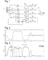
- Fig. 1 is a block diagram of a device for estimating a track-keeping stability-related quantity in a motor vehicle according to the present invention.
- the blocks in the block diagram can be thought of as being implemented in hardware circuitry, but it will be immediately apparent to a skilled person that any of them may be implemented as well by software in a microprocessor system.
- the device of fig. 1 is connected to a conventional digital data bus of a motor vehicle, e.g. a CAN bus. Via the CAN bus 1, the device receives input data, namely vehicle lateral acceleration AY, yaw rate YR, steering wheel angle SWA and vehicle longitudinal velocity Vel from appropriate sensors, not shown. All these variables are conventionally available in real time on a vehicle CAN bus.
- the device comprises five filters 2 1 to 2 5 , all of identical design. Each of the filters 2 1 to 2 5 has a control input which receives steering wheel angle data SWA from bus 1.
- a data input of filter 2 1 receives the lateral acceleration data AY.
- a data input of filter 2 2 receives the yaw rate data YR.
- a data input of filter 2 3 receives a first error signal representing the difference between the measured lateral acceleration AY and an expected lateral acceleration AY* which is calculated assuming that the vehicle is circulating at its measured longitudinal velocity Vel on a circular track, the radius of which is associated to the measured steering wheel angle SWA.
- the first error signal may thus be said to be representative of a discrepancy between the actual trajectory of the vehicle and the trajectory the driver wants the vehicle to follow.
- a desired yaw rate YR* is calculated based on the steering wheel angle SWA and the vehicle longitudinal velocity Vel, and a discrepancy between it and the measured yaw rate YR is input in the filter 2 4 as a second error signal.
- Filter 2 5 has the steering wheel angle signal SWA applied to it at its data input and at its control input.
- Fig. 2 is an exemplary plot of lateral acceleration data input into filter 2 1 during a slalom driving manoeuvre.
- the filter 2 1 forms the absolute value
- the output of filter 2 1 represented by curve C2
- the output of filter 2 1 represented by curve C2
- the output of filter 2 1 follows the curve C1 closely, e.g.
- the filter 2 1 detects that the rate of decrease of
- time intervals where fluctuations of the lateral acceleration due to rapid steering manoeuvres of the driver are suppressed in the output signal C2 are from t4 to t5, t6 to t7, and so on.
- the steering wheel angle signal SWA is not, since a large steering wheel angle at low speed does not necessarily imply a higher load on the tires than a small steering wheel angle at high speed. Therefore, in order to obtain a quantity better related to the tire stress, the output of filter 2 5 is multiplied with the vehicle speed Vel in a multiplier 3.
- Output data from filters 2 1 to 2 4 and multiplier 3 are applied as address data to look-up tables 4 1 to 4 5 .
- the output of each look-up table 4 i is weighted by a predetermined weighting factor w i in a multiplier 5 i .
- multipliers 5 i might be dispensed with by storing in the look-up tables 4 i characteristic functions w i *f i (x) instead of f i (x), as described above.
- the outputs of the multipliers 5 i are summed in adder 6.
- the tire degree of linearity ⁇ is very closely correlated to the instantaneous tire stiffness, so that a good approximation of the tire stiffness can be obtained by multiplying ⁇ by a constant factor.
- the characteristic F( ⁇ ) in look-up table 7 is a monotonically increasing function with decreasing slope, e.g. a portion of a parabola. Due to the decreasing slope of the characteristic F( ⁇ ), a predetermined variation in ⁇ will cause a rather small fluctuation in the output F( ⁇ ) of look-up table 7 when ⁇ is high, i.e. when the stability of the vehicle is high and the tires have tight hold on the road. When ⁇ is low, however, the predetermined variation causes a larger variation in the output of look-up table 7, so that in a situation where the stability of the vehicle is reduced, a clearly detectable variation is output from look-up table 7
- the effectiveness of the device of Fig. 1 might be tested by obtaining experimental data of the tire stiffness for a given type of motor vehicle at a large number of different values of AY, YR, SWA and Vel, and fitting the characteristics in look-up tables 2 1 , ..., 2 5 , and 7, so that the correlation between the output F( ⁇ ) of look-up table 7 for a given set of values of AY, YR, SWA, Vel and the measured tire stiffness at these same values is maximized.
- a curve C3 represents the measured side-slip angles ⁇
- a curve C4 illustrates side-slip angles ⁇ * estimated by the observer. Agreement between the two curves is good. There is hardly any delay between corresponding peaks of the two curves, and the difference between the peak values is not more than approximately 30%. There is no long-term drift of the estimated side-slip angles.
- a curve C5 in Fig. 4 plots side-slip angles estimated by the same observer using a constant value of the tire stiffness. There are peaks in C5 which have no counterpart in the measured curve C3, and the discrepancy between the peaks of the measured curve C3 and a corresponding peak of the estimated side-slip angle curve C5 is up to 60%.
Landscapes
- Engineering & Computer Science (AREA)
- Transportation (AREA)
- Mechanical Engineering (AREA)
- Steering Control In Accordance With Driving Conditions (AREA)
- Control Of Driving Devices And Active Controlling Of Vehicle (AREA)
- Regulating Braking Force (AREA)
- Tires In General (AREA)
- Traffic Control Systems (AREA)
Abstract
a) providing a plurality of characteristics (fi(x), i=1, 2, ..., 5), each of the characteristics (fi(x)) specifying a stability index as a function of at least one of the following variables (x):
- the effective vehicle lateral acceleration (AY),
- the effective vehicle yaw rate (YR),
- the difference between effective (AY) and expected (AY*) vehicle lateral accelerations,
- the difference between effective (YR) and expected (YR*) vehicle yaw rates,
- the product of steering wheel angle (SWA) and vehicle longitudinal velocity (Vel);
the characteristics (fi(x)) having a first argument range in which they are linear functions;
b) measuring values of the input variables (AY, YR, AY-AY*, YR-YR*, SWA) of each characteristic;
c) determining values of the stability indices associated to said input parameter values using said characteristics (fi(x)), and
d) calculating a sum (γ) of said stability indices.
Description
- The present invention relates to a method for estimating the stability and/or controllability of a vehicle in motion, specifically for judging the track-keeping capacity of a motor vehicle when cornering.
- It is known that under the influence of a lateral force, particularly the centrifugal force during cornering, the direction in which the wheels of the vehicle move may not be perpendicular to the wheel axles. The deviation between the direction perpendicular to the wheel axles and the effective direction of propagation is referred to as side-slip angle. At low lateral forces, the side-slip angle is directly proportional to the lateral force. At high lateral forces, this proportionality is no longer valid; the side-slip angle grows very fast with increasing lateral force and will diverge when the lateral force exceeds a certain threshold and the wheels begin to slide. If this happens, control over the vehicle is lost. It is difficult to predict this threshold since it depends on the friction coefficient between tire and road.
- It is therefore highly desirable to have a simple and efficient method for quantitatively estimating the track-keeping stability of a vehicle in motion in real time. The result of such a method might be used for warning a driver of a potentially dangerous situation before it becomes critical or for triggering automatic stabilizing operations.
- The present invention provides a particularly simple and efficient method for estimating a quantity representative of the track-keeping stability, which comprises the following steps:
- a) providing a plurality of characteristics, each of the characteristics specifying a stability index as a function of at least one of the following variables:
- the effective vehicle lateral acceleration,
- the effective vehicle yaw rate,
- the difference between effective and expected vehicle lateral accelerations,
- the difference between effective and expected vehicle yaw rates,
- the product of a steering wheel angle and vehicle longitudinal velocity,
the characteristics having a first argument range in which they are linear functions;
- b) measuring current values of the variables of each characteristic;
- c) determining the stability indices associated to said current values using said characteristics, and
- d) calculating a sum of said stability indices.
- It was found that by judiciously optimizing the above-mentioned characteristics, a stability-related quantity can be obtained, which is continuously variable and based on the numerical value of which driving conditions which would cause loss of control over the vehicle can be reliably predicted, so that appropriate countermeasures can be taken before control over the vehicle is actually lost.
- In order to facilitate the optimization of the characteristics, each characteristic should have the smallest possible number of variables. It was found that a single variable for each characteristic is sufficient to enable a reliable prediction.
- Since the characteristics have an argument range in which they are linear functions, the number of parameters needed to specify them is very limited, which facilitates further the task of optimizing them. Besides, when the method is carried out the linear nature of the characteristics facilitates their evaluation in real time.
- It is preferred that the characteristics are constant in second and third argument ranges adjacent to said first range and that they are continuous functions all over their first to third argument ranges. If the constant value e.g. in the third range is set to zero, each characteristic is specified completely by three parameters, e.g. by the borders of the first range and constant value of the characteristic in the second range, by its value at a predetermined argument in the first range, its slope in the first range and the constant value in the second range, or others.
- The above mentioned sum of the stability indices can be used directly as the stability-related quantity; preferably, the stability-related parameter is calculated as a monotonic non-linear function of the sum obtained in step D, the derivative of the function being higher in a range of said sum which is indicative of low track-keeping stability than in a range which is indicative of high track-keeping stability. In this way, a given variation of the sum will cause a larger variation of the stability-related parameter when stability is low than when it is high, so that a condition where stability drops below a critical threshold can be determined with high accuracy.
- In a practical embodiment, the characteristics are fitted so that the track-keeping stability-related quantity is proportional to the cornering stiffness of the vehicle's tires. In fact, for a given vehicle model the cornering stiffness under different driving conditions can be measured experimentally, and due to the small number of parameters of the characteristics, these can be fitted using methods known to the man of the art.
- Under slalom driving conditions, i.e. when a vehicle is going through curves in quickly alternating directions, there is an instant of each change of the cornering direction where the effective vehicle lateral acceleration and yaw rate become zero, which might cause the method to detect good stability in spite of the tires being under a substantial load. In order to prevent an overestimation of the stability under such circumstances, it is advisable to filter at least one of the measured input variable and to use the filtered input variable as an argument for one of the characteristics.
- Preferably, the step of filtering a measured input variable comprises the sub-steps of determining the rate of change of the steering wheel angle, of sampling the input variable and of replacing the measured input variable value by the sampled variable value while the rate of change exceeds the predetermined threshold.
- The replacing step is preferably carried out only if the steering wheel is approaching its neutral position.
- The invention may be embodied also in the form of a data processor program product comprising a data carrier in which program instructions for enabling a data processor to carry out the method defined above are recorded in machine readable form.
- A device for estimating a track-keeping stability-related quantity in a motor vehicle comprises
- a) memory for storing a plurality of characteristics, each of the characteristics specifying a stability index as a function of at least one of the following variables:
- the effective vehicle lateral acceleration,
- the effective vehicle yaw rate,
- the difference between effective and expected vehicle lateral accelerations,
- the difference between effective and expected vehicle yaw rates,
- the product of steering wheel angle and vehicle longitudinal velocity;
the characteristics having a first argument range in which they are linear functions;
- b) an input port for receiving values of the input variables of each characteristic;
- c) means for determining the stability index values associated to said input variable values using said characteristics, and
- d) means for calculating a sum of said stability index values.
- Further features and advantages of the invention will become apparent from the subsequent description of embodiments thereof referring to the appended drawings.
- Fig. 1
- is a block diagram of a device for estimating a track-keeping stability-related quantity according to the present invention;
- Fig. 2
- is an exemplary plot of measured lateral acceleration data as a function of time;
- Fig. 3
- is a plot illustrating pre-processed and filtered lateral acceleration data;
- Fig. 4
- is a plot illustrating a waveform of measured side-slip angles corresponding to the lateral acceleration data illustrated in
fig. 2 , and a waveform of side-slip angles estimated based on the acceleration data offig. 2 assuming constant tire stiffness; and - Fig. 5
- is a plot illustrating the same waveform of measured side-slip angles as in
Fig. 4 and a waveform of side-slip angles estimated based on the acceleration data offig. 2 assuming calculated assuming variable tire stiffness. -
Fig. 1 is a block diagram of a device for estimating a track-keeping stability-related quantity in a motor vehicle according to the present invention. The blocks in the block diagram can be thought of as being implemented in hardware circuitry, but it will be immediately apparent to a skilled person that any of them may be implemented as well by software in a microprocessor system. - The device of
fig. 1 is connected to a conventional digital data bus of a motor vehicle, e.g. a CAN bus. Via theCAN bus 1, the device receives input data, namely vehicle lateral acceleration AY, yaw rate YR, steering wheel angle SWA and vehicle longitudinal velocity Vel from appropriate sensors, not shown. All these variables are conventionally available in real time on a vehicle CAN bus. The device comprises fivefilters 21 to 25, all of identical design. Each of thefilters 21 to 25 has a control input which receives steering wheel angle data SWA frombus 1. A data input offilter 21 receives the lateral acceleration data AY. A data input offilter 22 receives the yaw rate data YR. A data input offilter 23 receives a first error signal representing the difference between the measured lateral acceleration AY and an expected lateral acceleration AY* which is calculated assuming that the vehicle is circulating at its measured longitudinal velocity Vel on a circular track, the radius of which is associated to the measured steering wheel angle SWA. The first error signal may thus be said to be representative of a discrepancy between the actual trajectory of the vehicle and the trajectory the driver wants the vehicle to follow. - Similarly, a desired yaw rate YR* is calculated based on the steering wheel angle SWA and the vehicle longitudinal velocity Vel, and a discrepancy between it and the measured yaw rate YR is input in the
filter 24 as a second error signal. -
Filter 25 has the steering wheel angle signal SWA applied to it at its data input and at its control input. -
Fig. 2 is an exemplary plot of lateral acceleration data input intofilter 21 during a slalom driving manoeuvre. As can be seen, the vehicle is cornering in a first direction from time = 1s to time = 3s, it is cornering in the opposite direction from time = 3s to time = 7s, it is cornering in the first direction again from time = 7s to time = 9s, and so on. In a first processing step, thefilter 21 forms the absolute value |AY| of the input data AY, represented by curve C1 infig. 3 . While the steering wheel is being rotated away from its neutral position, i.e. while the amount of SWA increases, the output offilter 21, represented by curve C2, follows the curve C1 closely, e.g. from time = 0 to time = t1 ≅ 2s. At time t1, thefilter 21 detects that the rate of decrease of |SWA| exceeds a predetermined threshold. It then samples the input C1 at t1 and outputs it as C2 until the rate of change of |SWA| drops below the threshold again at time t3. The zero crossing of AY at time t2 is suppressed in the output C2 offilter 21. - Other time intervals where fluctuations of the lateral acceleration due to rapid steering manoeuvres of the driver are suppressed in the output signal C2 are from t4 to t5, t6 to t7, and so on.
- The effect of the
filters 22 to 25 on the yaw rate signal YR, the error signals and the steering wheel angle signal SWA is similar to what is described above for the lateral acceleration AY and need therefore not be described in detail. - While lateral acceleration, yaw rate and error signals are quite closely related to tire stress, the steering wheel angle signal SWA is not, since a large steering wheel angle at low speed does not necessarily imply a higher load on the tires than a small steering wheel angle at high speed. Therefore, in order to obtain a quantity better related to the tire stress, the output of
filter 25 is multiplied with the vehicle speed Vel in amultiplier 3. - Output data from
filters 21 to 24 andmultiplier 3 are applied as address data to look-up tables 41 to 45. Each look-up table 4i, i=1, ..., 5, stores a characteristic function fi which can take values from 1 to 0, which has at least a first range of arguments in which it is linear, and which equals either 1 or 0 in second or third argument ranges adjacent to said first range. In other words, the characteristic function may be written as
wherein ai>0, bi>1, and x is the output offilter 2i, i=1, ..., 4 ormultiplier 7, as appropriate. The output of each look-up table 4i is weighted by a predetermined weighting factor wi in amultiplier 5i. The weighting factors are predetermined so that
- It is readily apparent that the
multipliers 5i might be dispensed with by storing in the look-up tables 4i characteristic functions wi*fi(x) instead of fi(x), as described above. - The outputs of the
multipliers 5i are summed inadder 6. The output γ ofadder 6 is referred to here as the tire degree of linearity γ. It can take any value from 0 to 1. If γ is close to 1, the behaviour of the tire can be regarded as linear, i.e.
- with C=constant is a good approximation for the relation between the side-slip angle α of the tire and the lateral force Fy to which the tire is subject. The smaller γ is, the less exact is the approximation, and if γ approaches zero, the tire is losing hold, and the vehicle is becoming unstable. The constant C is different for front and rear tires.
- Provided that the weighting factors wi in
multipliers 5i and the first ranges (bi -1)/ai ≤x<bi /ai of the characteristics in the look-up tables 4i are well optimized, the tire degree of linearity γ is very closely correlated to the instantaneous tire stiffness, so that a good approximation of the tire stiffness can be obtained by multiplying γ by a constant factor. - A still better approximation can be achieved if the tire degree of linearity γ is applied as an argument to a further characteristic F(γ) in look-up table 7. The characteristic F(γ) in look-up table 7 is a monotonically increasing function with decreasing slope, e.g. a portion of a parabola. Due to the decreasing slope of the characteristic F(γ), a predetermined variation in γ will cause a rather small fluctuation in the output F(γ) of look-up table 7 when γ is high, i.e. when the stability of the vehicle is high and the tires have tight hold on the road. When γ is low, however, the predetermined variation causes a larger variation in the output of look-up table 7, so that in a situation where the stability of the vehicle is reduced, a clearly detectable variation is output from look-up table 7
- The effectiveness of the device of
Fig. 1 might be tested by obtaining experimental data of the tire stiffness for a given type of motor vehicle at a large number of different values of AY, YR, SWA and Vel, and fitting the characteristics in look-up tables 21, ..., 25, and 7, so that the correlation between the output F(γ) of look-up table 7 for a given set of values of AY, YR, SWA, Vel and the measured tire stiffness at these same values is maximized. - In fact, optimization and a test for the effectiveness of the device were carried out in a slightly different way: The vehicle side-slip angle β was determined experimentally for a large number of different values of AY, YR, SWA and Vel. From F(γ), an estimated tire stiffness Cest was derived using the equation

- with C0=constant. This estimated tire stiffness Cest was input into a conventional Kalman filter-based observer for calculating an estimated vehicle side-slip angle β* at said different values of AY, YR, SWA and Vel. The parameters of the characteristics in look-up tables 4i and 7 were fitted so as to optimize the agreement between the calculated values β* of the side-slip angle and experimentally determined values of b at said different values of AY, YR, SWA and Vel.
- Side-slip angles β were also measured during the trajectory that gave the lateral acceleration data of
Fig. 2 . Tire stiffness data and Side-slip data β* were calculated for this trajectory using the optimized characteristics. InFig. 5 , a curve C3 represents the measured side-slip angles β, and a curve C4 illustrates side-slip angles β* estimated by the observer. Agreement between the two curves is good. There is hardly any delay between corresponding peaks of the two curves, and the difference between the peak values is not more than approximately 30%. There is no long-term drift of the estimated side-slip angles. - In contrast, a curve C5 in
Fig. 4 plots side-slip angles estimated by the same observer using a constant value of the tire stiffness. There are peaks in C5 which have no counterpart in the measured curve C3, and the discrepancy between the peaks of the measured curve C3 and a corresponding peak of the estimated side-slip angle curve C5 is up to 60%. -
- 1
- CAN bus
- 2
- Filter
- 3
- Multiplier
- 4
- Look-up table
- 5
- Multiplier
- 6
- Adder
- 7
- Look-up table
Claims (9)
- A method for estimating a track-keeping stability-related parameter (γ; F (γ)) in a motor vehicle comprising the steps ofa) providing a plurality of characteristics (fi(x), i=1, 2, ..., 5), each of the characteristics (fi(x)) specifying a stability index as a function of at least one of the following variables (x):- the effective vehicle lateral acceleration (AY),- the effective vehicle yaw rate (YR),- the difference between effective (AY) and expected (AY*) vehicle lateral accelerations,- the difference between effective (YR) and expected (YR*) vehicle yaw rates,- the product of steering wheel angle (SWA) and vehicle longitudinal velocity (Vel);
the characteristics (fi(x)) having a first argument range in which they are linear functions;b)measuring values of the input variables (AY, YR, AY-AY*, YR-YR*, SWA) of each characteristic;c) determining values of the stability indices associated to said input parameter values using said characteristics (fi(x)), andd) calculating a sum (γ) of said stability indices. - The method of claim 1, wherein said characteristics (fi(x)) are continuous functions and are constant in second and third argument ranges adjacent to said first range.
- The method of claim 1 or 2, wherein the track-keeping stability-related parameter (F(γ)) is calculated as a monotonic non-linear function (F) of the sum (γ)obtained in step d), the derivative (dF/dg) of the function (F) being higher in a range of said sum (γ)indicative of low track-keeping stability than in a range indicative of high track-keeping stability.
- The method of any of the preceding claims, wherein characteristics (fi(x), F(γ)) are fitted so that the track-keeping stability-related parameter (γ; F(γ)) is proportional to the cornering stiffness of the vehicle's tires.
- The method of any of the preceding claims, wherein step c) comprises steps of filtering at least one of said measured input variables (AY, YR, AY-AY*, YR-YR*, SWA) and of using said filtered input variable as an argument for one of said characteristics (fi(x)).
- The method of claim 5, wherein the step of filtering said measured input variable (AY, YR, AY-AY*, YR-YR*, SWA) comprises the sub-steps of determining the rate of change of the steering wheel angle (SWA), of sampling the input variable and of replacing the measured input variable value by the sampled variable value while the rate of change exceeds a predetermined threshold.
- The method of claim 6, wherein the replacing step is carried out only if the steering wheel is approaching its neutral position.
- A data processor program product comprising a data carrier in which program instructions for enabling a data processor to carry out the method of one of claims 1 to 7 are recorded in machine-readable form.
- A device for estimating a track-keeping stability-related parameter in a motor vehicle comprisinga) memory (21, ..., 25) for storing a plurality of characteristics (fi), each of the characteristics (fi) specifying a stability index as a function of at least one of the following variables:- the effective vehicle lateral acceleration (AY),- the effective vehicle yaw rate (YR),- the difference between effective (AY) and expected (AY*) vehicle lateral accelerations,- the difference between effective (YR) and expected (YR*) vehicle yaw rates,- the product of steering wheel angle (SWA) and vehicle longitudinal velocity (Vel);
the characteristics (fi) having a first argument range in which they are linear functions;b) an input port (1) for receiving input variable values of each characteristic (fi);c) means (2-5) for determining the stability indices (fi(x)) associated to said input variables (AY, YR, AY-AY*, YR-YR*, SWA) using said characteristics (fi), andd) means (6) for calculating a sum of said stability indices (fi(x)).
Priority Applications (3)
| Application Number | Priority Date | Filing Date | Title |
|---|---|---|---|
| EP08003319A EP2093115B1 (en) | 2008-02-23 | 2008-02-23 | Method for estimating vehicle track-keeping stability |
| DE602008004303T DE602008004303D1 (en) | 2008-02-23 | 2008-02-23 | Method for estimating the tracking stability of a vehicle |
| AT08003319T ATE494192T1 (en) | 2008-02-23 | 2008-02-23 | METHOD FOR ESTIMATING THE KEEPING STABILITY OF A VEHICLE |
Applications Claiming Priority (1)
| Application Number | Priority Date | Filing Date | Title |
|---|---|---|---|
| EP08003319A EP2093115B1 (en) | 2008-02-23 | 2008-02-23 | Method for estimating vehicle track-keeping stability |
Publications (2)
| Publication Number | Publication Date |
|---|---|
| EP2093115A1 true EP2093115A1 (en) | 2009-08-26 |
| EP2093115B1 EP2093115B1 (en) | 2011-01-05 |
Family
ID=39638870
Family Applications (1)
| Application Number | Title | Priority Date | Filing Date |
|---|---|---|---|
| EP08003319A Not-in-force EP2093115B1 (en) | 2008-02-23 | 2008-02-23 | Method for estimating vehicle track-keeping stability |
Country Status (3)
| Country | Link |
|---|---|
| EP (1) | EP2093115B1 (en) |
| AT (1) | ATE494192T1 (en) |
| DE (1) | DE602008004303D1 (en) |
Cited By (1)
| Publication number | Priority date | Publication date | Assignee | Title |
|---|---|---|---|---|
| WO2013087169A1 (en) * | 2011-12-16 | 2013-06-20 | Audi Ag | Control device for a motor vehicle, motor vehicle, and method for configuring the control device |
Families Citing this family (1)
| Publication number | Priority date | Publication date | Assignee | Title |
|---|---|---|---|---|
| CN112829760B (en) * | 2019-11-25 | 2022-05-24 | 宇通客车股份有限公司 | Vehicle driving track prediction method and system |
Citations (4)
| Publication number | Priority date | Publication date | Assignee | Title |
|---|---|---|---|---|
| US5862503A (en) * | 1994-11-25 | 1999-01-19 | Itt Automotive Europe Gmbh | System for driving stability control |
| US20030130775A1 (en) * | 2002-01-08 | 2003-07-10 | Jianbo Lu | Vehicle side slip angle estimation using dynamic blending and considering vehicle attitude information |
| DE10215464A1 (en) * | 2002-03-28 | 2003-10-16 | Volkswagen Ag | Determining method for an assessed value of a flotation angle in motor vehicles to be measured indirectly uses a non-linear differential equation to describe the flotation angle |
| US20070112474A1 (en) * | 2005-11-16 | 2007-05-17 | Shih-Ken Chen | Vehicle stability control with lateral dynamics feedback |
-
2008
- 2008-02-23 DE DE602008004303T patent/DE602008004303D1/en active Active
- 2008-02-23 EP EP08003319A patent/EP2093115B1/en not_active Not-in-force
- 2008-02-23 AT AT08003319T patent/ATE494192T1/en not_active IP Right Cessation
Patent Citations (4)
| Publication number | Priority date | Publication date | Assignee | Title |
|---|---|---|---|---|
| US5862503A (en) * | 1994-11-25 | 1999-01-19 | Itt Automotive Europe Gmbh | System for driving stability control |
| US20030130775A1 (en) * | 2002-01-08 | 2003-07-10 | Jianbo Lu | Vehicle side slip angle estimation using dynamic blending and considering vehicle attitude information |
| DE10215464A1 (en) * | 2002-03-28 | 2003-10-16 | Volkswagen Ag | Determining method for an assessed value of a flotation angle in motor vehicles to be measured indirectly uses a non-linear differential equation to describe the flotation angle |
| US20070112474A1 (en) * | 2005-11-16 | 2007-05-17 | Shih-Ken Chen | Vehicle stability control with lateral dynamics feedback |
Cited By (2)
| Publication number | Priority date | Publication date | Assignee | Title |
|---|---|---|---|---|
| WO2013087169A1 (en) * | 2011-12-16 | 2013-06-20 | Audi Ag | Control device for a motor vehicle, motor vehicle, and method for configuring the control device |
| US9630600B2 (en) | 2011-12-16 | 2017-04-25 | Audi Ag | Controller for a motor vehicle, motor vehicle, and method for configuring the controller |
Also Published As
| Publication number | Publication date |
|---|---|
| ATE494192T1 (en) | 2011-01-15 |
| DE602008004303D1 (en) | 2011-02-17 |
| EP2093115B1 (en) | 2011-01-05 |
Similar Documents
| Publication | Publication Date | Title |
|---|---|---|
| US6816799B2 (en) | Vehicle operating parameter determination system and method | |
| US6015192A (en) | System for estimating vehicle body speed and road surface friction coefficient | |
| EP2203340B1 (en) | Vehicle body speed estimating device | |
| EP1627790B1 (en) | Estimating method for road friction coefficient and vehicle slip angle estimating method | |
| EP1486391B1 (en) | Vehicle control device and vehicle control method | |
| US6308115B1 (en) | Vehicle running condition judgement device | |
| EP1396372B1 (en) | Cornering power control device and method | |
| EP3894289B1 (en) | Tire stiffness estimation and road friction estimation | |
| DE69331838T2 (en) | Device for calculating the banking angle of a vehicle | |
| US6470300B1 (en) | Method and system for detecting and localizing sensor defects in motor vehicles | |
| US9988043B2 (en) | Methods and systems for determining a vehicle spin-out condition | |
| EP2938507B1 (en) | System and method for monitoring an estimated wheel speed of a vehicle using a transmission output shaft sensor | |
| US10363939B2 (en) | Vehicle reference velocity estimation apparatus and method | |
| WO2012138286A1 (en) | Estimation of road inclination | |
| US6519523B2 (en) | Method and device for determining an unstable driving condition of a motor vehicle | |
| US20030074116A1 (en) | Method and device for determining offset values by a histogram method | |
| US6241324B1 (en) | Method of controlling anti-lock brake system for vehicles and method of finding control point in ABS | |
| EP2956344B1 (en) | A method for managing parameters that influence the driving resistance | |
| EP2093115B1 (en) | Method for estimating vehicle track-keeping stability | |
| US20180297633A1 (en) | Methods and systems for vehicle lateral force control | |
| US6427130B1 (en) | Method and device for regulating a quantity of motion representing the movement of a vehicle | |
| US20030014175A1 (en) | Method and device for regulating a docking process between two automobiles | |
| US6687594B1 (en) | Traction-slip control method with theoretical transversal acceleration and control circuit for carrying out such a traction-slip control method | |
| US6456923B1 (en) | Method for detecting cornering for a vehicle with an automatic transmission | |
| EP2093114A1 (en) | Method and apparatus for estimating the side-slip angle of a vehicle |
Legal Events
| Date | Code | Title | Description |
|---|---|---|---|
| PUAI | Public reference made under article 153(3) epc to a published international application that has entered the european phase |
Free format text: ORIGINAL CODE: 0009012 |
|
| AK | Designated contracting states |
Kind code of ref document: A1 Designated state(s): AT BE BG CH CY CZ DE DK EE ES FI FR GB GR HR HU IE IS IT LI LT LU LV MC MT NL NO PL PT RO SE SI SK TR |
|
| AX | Request for extension of the european patent |
Extension state: AL BA MK RS |
|
| 17P | Request for examination filed |
Effective date: 20100226 |
|
| 17Q | First examination report despatched |
Effective date: 20100322 |
|
| AKX | Designation fees paid |
Designated state(s): AT BE BG CH CY CZ DE DK EE ES FI FR GB GR HR HU IE IS IT LI LT LU LV MC MT NL NO PL PT RO SE SI SK TR |
|
| GRAP | Despatch of communication of intention to grant a patent |
Free format text: ORIGINAL CODE: EPIDOSNIGR1 |
|
| GRAS | Grant fee paid |
Free format text: ORIGINAL CODE: EPIDOSNIGR3 |
|
| GRAA | (expected) grant |
Free format text: ORIGINAL CODE: 0009210 |
|
| AK | Designated contracting states |
Kind code of ref document: B1 Designated state(s): AT BE BG CH CY CZ DE DK EE ES FI FR GB GR HR HU IE IS IT LI LT LU LV MC MT NL NO PL PT RO SE SI SK TR |
|
| REG | Reference to a national code |
Ref country code: GB Ref legal event code: FG4D |
|
| REG | Reference to a national code |
Ref country code: CH Ref legal event code: EP |
|
| REG | Reference to a national code |
Ref country code: IE Ref legal event code: FG4D |
|
| REF | Corresponds to: |
Ref document number: 602008004303 Country of ref document: DE Date of ref document: 20110217 Kind code of ref document: P |
|
| REG | Reference to a national code |
Ref country code: DE Ref legal event code: R096 Ref document number: 602008004303 Country of ref document: DE Effective date: 20110217 |
|
| REG | Reference to a national code |
Ref country code: NL Ref legal event code: VDEP Effective date: 20110105 |
|
| REG | Reference to a national code |
Ref country code: DE Ref legal event code: R081 Ref document number: 602008004303 Country of ref document: DE Owner name: GM GLOBAL TECHNOLOGY OPERATIONS LLC (N. D. GES, US Free format text: FORMER OWNER: GM GLOBAL TECHNOLOGY OPERATIONS, INC., DETROIT, MICH., US Effective date: 20110323 Ref country code: DE Ref legal event code: R081 Ref document number: 602008004303 Country of ref document: DE Owner name: GM GLOBAL TECHNOLOGY OPERATIONS LLC (N. D. GES, US Free format text: FORMER OWNER: GM GLOBAL TECHNOLOGY OPERATIONS, INC., DETROIT, US Effective date: 20110323 |
|
| PG25 | Lapsed in a contracting state [announced via postgrant information from national office to epo] |
Ref country code: SI Free format text: LAPSE BECAUSE OF FAILURE TO SUBMIT A TRANSLATION OF THE DESCRIPTION OR TO PAY THE FEE WITHIN THE PRESCRIBED TIME-LIMIT Effective date: 20110105 |
|
| LTIE | Lt: invalidation of european patent or patent extension |
Effective date: 20110105 |
|
| REG | Reference to a national code |
Ref country code: CH Ref legal event code: PFA Owner name: GM GLOBAL TECHNOLOGY OPERATIONS LLC Free format text: GM GLOBAL TECHNOLOGY OPERATIONS LLC#300 RENAISSANCE CENTER#DETROIT, MI 48265-3000 (US) -TRANSFER TO- GM GLOBAL TECHNOLOGY OPERATIONS LLC#300 RENAISSANCE CENTER#DETROIT, MI 48265-3000 (US) |
|
| RAP2 | Party data changed (patent owner data changed or rights of a patent transferred) |
Owner name: GM GLOBAL TECHNOLOGY OPERATIONS LLC |
|
| PG25 | Lapsed in a contracting state [announced via postgrant information from national office to epo] |
Ref country code: SE Free format text: LAPSE BECAUSE OF FAILURE TO SUBMIT A TRANSLATION OF THE DESCRIPTION OR TO PAY THE FEE WITHIN THE PRESCRIBED TIME-LIMIT Effective date: 20110105 Ref country code: LV Free format text: LAPSE BECAUSE OF FAILURE TO SUBMIT A TRANSLATION OF THE DESCRIPTION OR TO PAY THE FEE WITHIN THE PRESCRIBED TIME-LIMIT Effective date: 20110105 Ref country code: NO Free format text: LAPSE BECAUSE OF FAILURE TO SUBMIT A TRANSLATION OF THE DESCRIPTION OR TO PAY THE FEE WITHIN THE PRESCRIBED TIME-LIMIT Effective date: 20110405 Ref country code: LT Free format text: LAPSE BECAUSE OF FAILURE TO SUBMIT A TRANSLATION OF THE DESCRIPTION OR TO PAY THE FEE WITHIN THE PRESCRIBED TIME-LIMIT Effective date: 20110105 Ref country code: IS Free format text: LAPSE BECAUSE OF FAILURE TO SUBMIT A TRANSLATION OF THE DESCRIPTION OR TO PAY THE FEE WITHIN THE PRESCRIBED TIME-LIMIT Effective date: 20110505 Ref country code: ES Free format text: LAPSE BECAUSE OF FAILURE TO SUBMIT A TRANSLATION OF THE DESCRIPTION OR TO PAY THE FEE WITHIN THE PRESCRIBED TIME-LIMIT Effective date: 20110416 Ref country code: PT Free format text: LAPSE BECAUSE OF FAILURE TO SUBMIT A TRANSLATION OF THE DESCRIPTION OR TO PAY THE FEE WITHIN THE PRESCRIBED TIME-LIMIT Effective date: 20110505 Ref country code: HR Free format text: LAPSE BECAUSE OF FAILURE TO SUBMIT A TRANSLATION OF THE DESCRIPTION OR TO PAY THE FEE WITHIN THE PRESCRIBED TIME-LIMIT Effective date: 20110105 Ref country code: GR Free format text: LAPSE BECAUSE OF FAILURE TO SUBMIT A TRANSLATION OF THE DESCRIPTION OR TO PAY THE FEE WITHIN THE PRESCRIBED TIME-LIMIT Effective date: 20110406 |
|
| PG25 | Lapsed in a contracting state [announced via postgrant information from national office to epo] |
Ref country code: NL Free format text: LAPSE BECAUSE OF FAILURE TO SUBMIT A TRANSLATION OF THE DESCRIPTION OR TO PAY THE FEE WITHIN THE PRESCRIBED TIME-LIMIT Effective date: 20110105 Ref country code: PL Free format text: LAPSE BECAUSE OF FAILURE TO SUBMIT A TRANSLATION OF THE DESCRIPTION OR TO PAY THE FEE WITHIN THE PRESCRIBED TIME-LIMIT Effective date: 20110105 Ref country code: BE Free format text: LAPSE BECAUSE OF FAILURE TO SUBMIT A TRANSLATION OF THE DESCRIPTION OR TO PAY THE FEE WITHIN THE PRESCRIBED TIME-LIMIT Effective date: 20110105 Ref country code: FI Free format text: LAPSE BECAUSE OF FAILURE TO SUBMIT A TRANSLATION OF THE DESCRIPTION OR TO PAY THE FEE WITHIN THE PRESCRIBED TIME-LIMIT Effective date: 20110105 Ref country code: BG Free format text: LAPSE BECAUSE OF FAILURE TO SUBMIT A TRANSLATION OF THE DESCRIPTION OR TO PAY THE FEE WITHIN THE PRESCRIBED TIME-LIMIT Effective date: 20110405 Ref country code: AT Free format text: LAPSE BECAUSE OF FAILURE TO SUBMIT A TRANSLATION OF THE DESCRIPTION OR TO PAY THE FEE WITHIN THE PRESCRIBED TIME-LIMIT Effective date: 20110105 Ref country code: CY Free format text: LAPSE BECAUSE OF FAILURE TO SUBMIT A TRANSLATION OF THE DESCRIPTION OR TO PAY THE FEE WITHIN THE PRESCRIBED TIME-LIMIT Effective date: 20110105 |
|
| PG25 | Lapsed in a contracting state [announced via postgrant information from national office to epo] |
Ref country code: MC Free format text: LAPSE BECAUSE OF NON-PAYMENT OF DUE FEES Effective date: 20110228 |
|
| PG25 | Lapsed in a contracting state [announced via postgrant information from national office to epo] |
Ref country code: EE Free format text: LAPSE BECAUSE OF FAILURE TO SUBMIT A TRANSLATION OF THE DESCRIPTION OR TO PAY THE FEE WITHIN THE PRESCRIBED TIME-LIMIT Effective date: 20110105 Ref country code: DK Free format text: LAPSE BECAUSE OF FAILURE TO SUBMIT A TRANSLATION OF THE DESCRIPTION OR TO PAY THE FEE WITHIN THE PRESCRIBED TIME-LIMIT Effective date: 20110105 |
|
| PLBE | No opposition filed within time limit |
Free format text: ORIGINAL CODE: 0009261 |
|
| STAA | Information on the status of an ep patent application or granted ep patent |
Free format text: STATUS: NO OPPOSITION FILED WITHIN TIME LIMIT |
|
| REG | Reference to a national code |
Ref country code: IE Ref legal event code: MM4A |
|
| PG25 | Lapsed in a contracting state [announced via postgrant information from national office to epo] |
Ref country code: CZ Free format text: LAPSE BECAUSE OF FAILURE TO SUBMIT A TRANSLATION OF THE DESCRIPTION OR TO PAY THE FEE WITHIN THE PRESCRIBED TIME-LIMIT Effective date: 20110105 Ref country code: RO Free format text: LAPSE BECAUSE OF FAILURE TO SUBMIT A TRANSLATION OF THE DESCRIPTION OR TO PAY THE FEE WITHIN THE PRESCRIBED TIME-LIMIT Effective date: 20110105 Ref country code: SK Free format text: LAPSE BECAUSE OF FAILURE TO SUBMIT A TRANSLATION OF THE DESCRIPTION OR TO PAY THE FEE WITHIN THE PRESCRIBED TIME-LIMIT Effective date: 20110105 |
|
| 26N | No opposition filed |
Effective date: 20111006 |
|
| PG25 | Lapsed in a contracting state [announced via postgrant information from national office to epo] |
Ref country code: IT Free format text: LAPSE BECAUSE OF FAILURE TO SUBMIT A TRANSLATION OF THE DESCRIPTION OR TO PAY THE FEE WITHIN THE PRESCRIBED TIME-LIMIT Effective date: 20110105 Ref country code: MT Free format text: LAPSE BECAUSE OF FAILURE TO SUBMIT A TRANSLATION OF THE DESCRIPTION OR TO PAY THE FEE WITHIN THE PRESCRIBED TIME-LIMIT Effective date: 20110105 |
|
| PG25 | Lapsed in a contracting state [announced via postgrant information from national office to epo] |
Ref country code: IE Free format text: LAPSE BECAUSE OF NON-PAYMENT OF DUE FEES Effective date: 20110223 |
|
| REG | Reference to a national code |
Ref country code: DE Ref legal event code: R097 Ref document number: 602008004303 Country of ref document: DE Effective date: 20111006 |
|
| REG | Reference to a national code |
Ref country code: CH Ref legal event code: PL |
|
| PG25 | Lapsed in a contracting state [announced via postgrant information from national office to epo] |
Ref country code: CH Free format text: LAPSE BECAUSE OF NON-PAYMENT OF DUE FEES Effective date: 20120229 Ref country code: LI Free format text: LAPSE BECAUSE OF NON-PAYMENT OF DUE FEES Effective date: 20120229 |
|
| PG25 | Lapsed in a contracting state [announced via postgrant information from national office to epo] |
Ref country code: LU Free format text: LAPSE BECAUSE OF NON-PAYMENT OF DUE FEES Effective date: 20110223 |
|
| PG25 | Lapsed in a contracting state [announced via postgrant information from national office to epo] |
Ref country code: TR Free format text: LAPSE BECAUSE OF FAILURE TO SUBMIT A TRANSLATION OF THE DESCRIPTION OR TO PAY THE FEE WITHIN THE PRESCRIBED TIME-LIMIT Effective date: 20110105 |
|
| PG25 | Lapsed in a contracting state [announced via postgrant information from national office to epo] |
Ref country code: HU Free format text: LAPSE BECAUSE OF FAILURE TO SUBMIT A TRANSLATION OF THE DESCRIPTION OR TO PAY THE FEE WITHIN THE PRESCRIBED TIME-LIMIT Effective date: 20110105 |
|
| REG | Reference to a national code |
Ref country code: FR Ref legal event code: PLFP Year of fee payment: 9 |
|
| REG | Reference to a national code |
Ref country code: FR Ref legal event code: PLFP Year of fee payment: 10 |
|
| PGFP | Annual fee paid to national office [announced via postgrant information from national office to epo] |
Ref country code: DE Payment date: 20170214 Year of fee payment: 10 Ref country code: FR Payment date: 20170112 Year of fee payment: 10 |
|
| PGFP | Annual fee paid to national office [announced via postgrant information from national office to epo] |
Ref country code: GB Payment date: 20170222 Year of fee payment: 10 |
|
| REG | Reference to a national code |
Ref country code: DE Ref legal event code: R119 Ref document number: 602008004303 Country of ref document: DE |
|
| GBPC | Gb: european patent ceased through non-payment of renewal fee |
Effective date: 20180223 |
|
| REG | Reference to a national code |
Ref country code: FR Ref legal event code: ST Effective date: 20181031 |
|
| PG25 | Lapsed in a contracting state [announced via postgrant information from national office to epo] |
Ref country code: DE Free format text: LAPSE BECAUSE OF NON-PAYMENT OF DUE FEES Effective date: 20180901 |
|
| PG25 | Lapsed in a contracting state [announced via postgrant information from national office to epo] |
Ref country code: GB Free format text: LAPSE BECAUSE OF NON-PAYMENT OF DUE FEES Effective date: 20180223 Ref country code: FR Free format text: LAPSE BECAUSE OF NON-PAYMENT OF DUE FEES Effective date: 20180228 |