EP2093065A1 - An Ink Supply System for Printers - Google Patents
An Ink Supply System for Printers Download PDFInfo
- Publication number
- EP2093065A1 EP2093065A1 EP09152388A EP09152388A EP2093065A1 EP 2093065 A1 EP2093065 A1 EP 2093065A1 EP 09152388 A EP09152388 A EP 09152388A EP 09152388 A EP09152388 A EP 09152388A EP 2093065 A1 EP2093065 A1 EP 2093065A1
- Authority
- EP
- European Patent Office
- Prior art keywords
- reservoir
- ink
- filter
- printing head
- pressure
- Prior art date
- Legal status (The legal status is an assumption and is not a legal conclusion. Google has not performed a legal analysis and makes no representation as to the accuracy of the status listed.)
- Granted
Links
Images
Classifications
-
- B—PERFORMING OPERATIONS; TRANSPORTING
- B41—PRINTING; LINING MACHINES; TYPEWRITERS; STAMPS
- B41J—TYPEWRITERS; SELECTIVE PRINTING MECHANISMS, i.e. MECHANISMS PRINTING OTHERWISE THAN FROM A FORME; CORRECTION OF TYPOGRAPHICAL ERRORS
- B41J2/00—Typewriters or selective printing mechanisms characterised by the printing or marking process for which they are designed
- B41J2/005—Typewriters or selective printing mechanisms characterised by the printing or marking process for which they are designed characterised by bringing liquid or particles selectively into contact with a printing material
- B41J2/01—Ink jet
- B41J2/17—Ink jet characterised by ink handling
- B41J2/175—Ink supply systems ; Circuit parts therefor
Definitions
- the invention relates an ink supply system for inkjet or glaze printers destined for decorating ceramic tiles.
- closed-circuit ink supply systems in which the circulation is not due to a height difference between the two tanks, but is obtained with two pressure control devices, which are associated to both the tanks, such as to impose a predetermined difference between them.
- the ink On crossing the filter 41, the ink is rid of any particles of dirt and/or air bubbles which might have formed in the reservoir 2.
Landscapes
- Ink Jet (AREA)
- Particle Formation And Scattering Control In Inkjet Printers (AREA)
- Labeling Devices (AREA)
Abstract
Description
- The invention relates an ink supply system for inkjet or glaze printers destined for decorating ceramic tiles.
- In the following reference with be made to ink, though the term should be taken to refer also to ceramic glazes.
- As is known, an inkjet printer exhibits a supply system of the ink which comprises at least a printing head, which is connected to a relative tank of ink, and is provided with a plurality of very small dispensing nozzles through which the ink is made to exit in a controlled way, in order to be applied on the surface to be printed on.
- In traditional inkjet printers, the printing head is the terminal of a simple supply conduit, in which the ink runs in a single direction from the tank towards the dispensing nozzles.
- The most up-to-date printing heads are inserted in a closed circuit in which, when the printing operations are stopped, the ink is made to circulate continually, such as to create a constant flow passing through the printing head without exiting from the dispensing nozzles. During this circulation, the ink is generally filtered each time before crossing the printing head, such as to eliminate the dirt and/or air bubbles which might be present in it.
- In order to realise this system, printing heads comprise, apart from the above-mentioned dispensing nozzles, also an inlet conduit and an outlet conduit for the ink. The inlet conduit is connected to an upper storage reservoir, while the outlet conduit is connected to a lower storage reservoir, which is at a lower level than the first. Both tanks are kept at atmospheric pressure. The lower reservoir is in communication with the ink tank, and is connected to the upper reservoir through a recycling pump.
- In this way, the height difference between the two tanks enables the ink to run from the upper reservoir to the lower reservoir, crossing the printing head, while the recycling pump pushes the ink which has accumulated into the lower reservoir, newly towards the upper reservoir.
- Though being rather efficient, this ink supply system has exhibited some drawbacks relating to calibration and installation.
- In particular, in order to overcome the circuit impedance and to guarantee a constant ink flow through the printing head, it is necessary for the upper and lower reservoirs to be separated by a considerable difference in level, which leads to a significant increase in the size of the system.
- The level difference must also be accurately calibrated such as to create a constant slight depression at the printing nozzles of the printing head, so that the ink cannot accidentally exit due to the vibrations or to small impacts, thus introducing a series of not-irrelevant constructional difficulties.
- With the aim of eliminating these drawbacks, closed-circuit ink supply systems have been developed, in which the circulation is not due to a height difference between the two tanks, but is obtained with two pressure control devices, which are associated to both the tanks, such as to impose a predetermined difference between them.
- This solution enables the above-mentioned calibration and installation problems to be obviated, but however presents a considerable plant complication and thus a considerable hike in production costs.
- The aim of the present invention is to resolve the drawbacks of supply systems based on a level difference, with a more rational, simple and relatively inexpensive solution with respect to those at present available. The aim is attained by the characteristics of the invention as reported in the independent claims. The dependent claims delineate preferred and/or particularly advantageous aspects of the invention.
- In particular, an ink supply system is provided comprising two storage reservoirs which are reciprocally connected in a closed circuit by a delivery line, in which a printing head is inserted, which printing head is provided with at least an ink dispensing nozzle, and by a return line, in which a recycling pump is inserted.
- According to the invention, a first reservoir is open to the atmosphere through a breather mouth, while the second reservoir is associated to pressure control means, which internally maintain a pressure level that is lower than atmospheric pressure.
- Thanks to this solution, during pauses in printing, the recycling of the ink is created by the pressure difference between the tanks, caused by the depression imposed in the second tank.
- The tanks can thus both be located at the same height, obviating the drawbacks in non-level systems, while the plant layout is much simpler and more economical than those at present available, as only one of the two tanks has to be provided with pressure control means.
- Further, the pressure control means enable a precise calibration of the pressure difference between the two tanks, effectively preventing undesired ink leaks from the system during recycling.
- Further characteristics and advantages of the invention will better emerge from a reading of the following description provided by way of non-limiting example, with the aid of the figures illustrated in the accompanying tables of drawings.
-
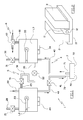
Figure 1 is a plant layout of the ink supply system of the invention, which is destined for an inkjet printer of a professional type. -
Figure 2 is a schematic view in perspective elevation of a preferred embodiment of some components of the system offigure 1 . - The ink supply system, denoted in its entirety by 1, comprises two storage reservoirs, respectively 2 and 3, which are positioned at a same height, and are reciprocally connected in a closed circuit by a delivery line 4 and a
return line 5. - The
reservoir 2 comprises abreather mouth 20 opening directly into the atmosphere, which is checked by aclosing solenoid 21, and aninlet conduit 22, through which the ink contained in a tank (not illustrated) is supplied internally of thereservoir 2. - The
reservoir 2 further comprises alevel sensor 23, which detects the height of the level L2 of ink internally of thereservoir 2, and aheater 24, which regulates the temperature of the ink. - Similarly, the
reservoir 3 comprises abreather mouth 30 which opens directly into the atmosphere, and which is checked by aclosing solenoid 31, alevel sensor 33 for detecting the height of the level L3 of the ink internally of thereservoir 3, and aheater 34, for regulating the temperature of the ink. - The
level sensors - The
heaters figure 2 . - In particular, the
reservoirs single support base 10, which exhibits a raisedlongitudinal wall 11 which is interposed contactingly between thereservoirs - The
support base 10 is realised in a material having a high heat conductivity, and is crossed by a longitudinally-developingelectrical resistance 12, which is housed internally of the raisedwall 11 and is connected to an electrical supply circuit (not illustrated). - In this way, the
electrical resistance 12 is able to heat both the ink contained in thereservoir 2 and the ink contained in thereservoir 3, performing the function of bothheaters figure 1 . - The
reservoir 3 further comprises pressure control and regulation means, denoted in their entirety by 6, which set internally thereof a predetermined pressure value, lower than atmospheric pressure. - In the illustrated example, the control means 6 comprise a
venturi tube 60, which is connected with thereservoir 3 via aconduit 61 which opens at the narrow section of theventuri tube 60. Theventuri tube 60 is crossed by a continuous air flow, such as to obtain a pressure drop in the narrowed section, and thus to create a depression in thereservoir 3. - A known-
type printing head 7 is inserted in the delivery line 4, whichprinting head 7 is positioned at a lower height than thereservoirs - The
printing head 7 schematically comprises aninlet 70, anoutlet 71 and a plurality of small ink-dispensingnozzles 72, open to the atmosphere. - The
inlet 70 is connected to thereservoir 2 via afirst conduit 40, along which anink filter 41 is inserted, while theoutlet 71 is connected to thereservoir 3 via asecond conduit 42 of the delivery line 4. - The
return line 5 comprises asingle conduit 50 in which arecycling pump 52 is inserted, which collects ink from anoutlet mouth 35 of thereservoir 3 in order to push it towards aninlet mouth 25 of thereservoir 2. Theinlet mouth 25 is located higher than theoutlet mouth 35, such as to prevent backflow of the ink. - An
ink filter 5 is also inserted in the line, which is interposed between therecycling pump 52 and thereservoir 2. - When the
supply system 1 is active, theheaters respective reservoirs - The
breather mouth 20 of thereservoir 2 is open, such that the pressure internally of thereservoir 2 is always atmospheric, while thebreather mouth 30 of thereservoir 3 is kept closed by thesolenoid 31. - At the same time a continuous air flow is made to cross the
venturi tube 60, such as to place thereservoir 3 in depression and thus consequently impose a predetermined pressure difference between thereservoir 3 and thereservoir 2. - When the printer is not required for printing, the pressure in the
reservoir 3 is regulated to a minimum level, i.e. high depression, such that the pressure difference between thereservoirs - In this way, a continuous ink flow is set up in the delivery line 4, which ink flow, leaving the
reservoir 2, first crosses thefilter 41, then theprinting head 7 without exiting the dispensingnozzles 72, and finally rises and returns internally of thereservoir 3. - On crossing the
filter 41, the ink is rid of any particles of dirt and/or air bubbles which might have formed in thereservoir 2. - When the
sensor 33 detects that the level L3 of the ink in thereservoir 3 has exceeded a predetermined threshold value, therecycling pump 52 enters into operation, such as to source ink from thereservoir 3, pass it through thefilter 51 and newly pour it internally of thereservoir 2, completing the cycle. - On crossing the
filter 51 the ink is purified of any particles of dirt and/or air bubbles which might have formed in thereservoir 3, or on passing through therecycling pump 52. - During the printing operations, the pressure in the
reservoir 3 is increased, i.e. the depression is reduced, such that the pressure difference between thereservoirs - In this way, the ink runs only along the
first tract 40 of the delivery line 4, flowing from thereservoir 2 towards theprinting head 7. - The ink passes through the
filter 41, in which it is purified, and when it reaches theprinting head 7 it exits through the dispensingnozzles 72 which are at atmospheric pressure and is deposited on the surface to be printed. - When the
sensor 23 detects that the level L2 of the ink in thereservoir 2 has fallen below a predetermined threshold level, the system supplies fresh ink from the tank to thereservoir 2, through theinlet conduit 22. - Finally, when the
supply system 1 is deactivated, thesolenoid 21 closes thebreather mouth 20 of thereservoir 2, such that the ink remains confined inside the closed circuit and cannot exit the dispensingnozzles 72 of theprinting head 7. - Obviously a technical expert in the sector might make numerous modifications of a technical-applicational nature to the above-described supply system, without its forsaking the ambit of the invention as claimed herein below.
Claims (9)
- An ink supply system for inkjet printers, comprising two storage reservoirs (2, 3) which are reciprocally connected by a delivery line (4), in which a printing head (7) provided with at least a dispensing nozzle (72) of the ink is inserted, and by a return line (5), in which a recycling pump (52) is inserted, characterised in that a first storage reservoir (2) is open to the atmosphere through a breather mouth (20) and a second reservoir (3) is associated to pressure control means (6) which internally maintain a pressure level which is lower than an atmospheric pressure.
- The system of claim 1, characterised in that the first reservoir (2) and the second reservoir (3) are located at a same height.
- The system of claim 1, characterised in that the pressure control means (6) comprise a venturi tube (60) which is in communication with the second reservoir (3) via a conduit (61) which opens at a narrowed section of the venturi tube (60).
- The system of claim 1, characterised in that it comprises heating means (24, 34) for regulating the temperature of the ink in the first reservoir (2) and the second reservoir (3).
- The system of claim 4, characterised in that the heating means (24, 34) comprise a single body (10) of a heat-conducting material, which single body (10) is located in contact with both reservoirs (2, 3) and which is crossed by at least an electrical resistance (12).
- The system of claim 1, characterised in that it comprises a first filter (41) of the ink, which first filter (41) is inserted along the delivery line (4) between the first reservoir (2) and the printing head (7).
- The system of claim 1, characterised in that it comprises a second filter (51) of the ink, which second filter (51) is inserted along the return line (5), between the recycling pump (52) and the first reservoir (2).
- The system of claim 1, characterised in that the first reservoir (2) comprises an inlet conduit (22), via which the first reservoir (2) is connected to a tank of the ink.
- The system of claim 1, characterised in that the first reservoir (2) and the second reservoir (3) are singly provided with a level sensor (23, 33).
Applications Claiming Priority (1)
| Application Number | Priority Date | Filing Date | Title |
|---|---|---|---|
| IT000022A ITRE20080022A1 (en) | 2008-02-19 | 2008-02-19 | INK FEEDING SYSTEM FOR PRINTERS |
Publications (2)
| Publication Number | Publication Date |
|---|---|
| EP2093065A1 true EP2093065A1 (en) | 2009-08-26 |
| EP2093065B1 EP2093065B1 (en) | 2010-09-22 |
Family
ID=40291872
Family Applications (1)
| Application Number | Title | Priority Date | Filing Date |
|---|---|---|---|
| EP09152388A Active EP2093065B1 (en) | 2008-02-19 | 2009-02-09 | An Ink Supply System for Printers |
Country Status (6)
| Country | Link |
|---|---|
| EP (1) | EP2093065B1 (en) |
| AT (1) | ATE482086T1 (en) |
| DE (1) | DE602009000203D1 (en) |
| ES (1) | ES2350752T3 (en) |
| IT (1) | ITRE20080022A1 (en) |
| PT (1) | PT2093065E (en) |
Cited By (14)
| Publication number | Priority date | Publication date | Assignee | Title |
|---|---|---|---|---|
| CN102673178A (en) * | 2011-02-28 | 2012-09-19 | 普罗杰塔工程有限责任公司 | Printing machine for printing on tiles and the like |
| WO2012168913A1 (en) | 2011-06-08 | 2012-12-13 | Olivetti S.P.A. | Ink- jet printing device |
| CN103144438A (en) * | 2013-03-06 | 2013-06-12 | 佛山市三水盈捷精密机械有限公司 | Ink supply system of ink jet printer and control method of ink supply system |
| WO2014037823A1 (en) | 2012-09-04 | 2014-03-13 | Projecta Engineering S.R.L. | Method and machine for the digital decoration of products with granular materials and the like |
| WO2015030736A1 (en) * | 2013-08-27 | 2015-03-05 | Hewlett-Packard Development Company, L. P. | Selectively provide pressure differences between reservoirs to cause printing fluid movement |
| CN106274080A (en) * | 2016-08-09 | 2017-01-04 | 佛山市三水盈捷精密机械有限公司 | Weaving digital decorating machine |
| WO2018182581A1 (en) * | 2017-03-28 | 2018-10-04 | Hewlett-Packard Development Company, L.P. | Fluid delivering in a printer |
| US10220625B2 (en) | 2015-04-23 | 2019-03-05 | Hewlett-Packard Development Company, L.P. | Liquid container |
| US10850521B2 (en) | 2015-10-29 | 2020-12-01 | Hewlett-Packard Development Company, L.P. | Ink storage unit having variable volume reservoirs |
| CN114454621A (en) * | 2021-12-30 | 2022-05-10 | 宁波荣大创想智造科技有限公司 | Ink supply system of ink-jet printer |
| JP2023031280A (en) * | 2021-08-24 | 2023-03-08 | セメス株式会社 | Substrate processing liquid supply unit and substrate processing apparatus provided with the same |
| WO2024204862A1 (en) * | 2023-03-29 | 2024-10-03 | 京セラドキュメントソリューションズ株式会社 | Deaeration device and inkjet recording device |
| WO2024204855A1 (en) * | 2023-03-29 | 2024-10-03 | 京セラドキュメントソリューションズ株式会社 | Deaeration device, inkjet recording device, and deaeration method |
| WO2024242093A1 (en) * | 2023-05-24 | 2024-11-28 | 京セラ株式会社 | Liquid storage tank, liquid circulation device, recording device equipped with same, and liquid storage tank group |
Families Citing this family (1)
| Publication number | Priority date | Publication date | Assignee | Title |
|---|---|---|---|---|
| ITVR20110243A1 (en) | 2011-12-30 | 2013-07-01 | Projecta Engineering S R L | WARDROBE FOR STORAGE OF INK, ENAMEL AND SIMILAR PRINTING MODULES |
Citations (7)
| Publication number | Priority date | Publication date | Assignee | Title |
|---|---|---|---|---|
| US3930258A (en) | 1975-01-13 | 1975-12-30 | Dick Co Ab | Ink monitoring and automatic fluid replenishing apparatus for ink jet printer |
| EP1361066A1 (en) * | 2000-06-29 | 2003-11-12 | Agfa-Gevaert N.V. | A fluid supply system including a degassing unit |
| US20070279461A1 (en) | 2006-06-05 | 2007-12-06 | Fuji Xerox Co., Ltd. | Droplet discharge apparatus |
| EP1886815A1 (en) | 2005-06-01 | 2008-02-13 | Canon Finetech Inc. | Print module, information processing device, print system, print unit, ink supply unit, print method, and program |
| US20080158321A1 (en) * | 2006-12-28 | 2008-07-03 | Toshiba Tec Kabushiki Kaisha | Ink jet recording apparatus, ink supplying mechanism and ink jet recording method |
| US20080158307A1 (en) * | 2006-12-28 | 2008-07-03 | Toshiba Tec Kabushiki Kaisha | Ink jet recording apparatus, ink supplying mechanism and ink supplying method |
| US20090009544A1 (en) * | 2007-07-05 | 2009-01-08 | Seiko Epson Corporation | Fluid ejecting apparatus and method for transporting fluid |
-
2008
- 2008-02-19 IT IT000022A patent/ITRE20080022A1/en unknown
-
2009
- 2009-02-09 DE DE602009000203T patent/DE602009000203D1/en active Active
- 2009-02-09 PT PT09152388T patent/PT2093065E/en unknown
- 2009-02-09 ES ES09152388T patent/ES2350752T3/en active Active
- 2009-02-09 AT AT09152388T patent/ATE482086T1/en active
- 2009-02-09 EP EP09152388A patent/EP2093065B1/en active Active
Patent Citations (7)
| Publication number | Priority date | Publication date | Assignee | Title |
|---|---|---|---|---|
| US3930258A (en) | 1975-01-13 | 1975-12-30 | Dick Co Ab | Ink monitoring and automatic fluid replenishing apparatus for ink jet printer |
| EP1361066A1 (en) * | 2000-06-29 | 2003-11-12 | Agfa-Gevaert N.V. | A fluid supply system including a degassing unit |
| EP1886815A1 (en) | 2005-06-01 | 2008-02-13 | Canon Finetech Inc. | Print module, information processing device, print system, print unit, ink supply unit, print method, and program |
| US20070279461A1 (en) | 2006-06-05 | 2007-12-06 | Fuji Xerox Co., Ltd. | Droplet discharge apparatus |
| US20080158321A1 (en) * | 2006-12-28 | 2008-07-03 | Toshiba Tec Kabushiki Kaisha | Ink jet recording apparatus, ink supplying mechanism and ink jet recording method |
| US20080158307A1 (en) * | 2006-12-28 | 2008-07-03 | Toshiba Tec Kabushiki Kaisha | Ink jet recording apparatus, ink supplying mechanism and ink supplying method |
| US20090009544A1 (en) * | 2007-07-05 | 2009-01-08 | Seiko Epson Corporation | Fluid ejecting apparatus and method for transporting fluid |
Cited By (25)
| Publication number | Priority date | Publication date | Assignee | Title |
|---|---|---|---|---|
| CN102673178A (en) * | 2011-02-28 | 2012-09-19 | 普罗杰塔工程有限责任公司 | Printing machine for printing on tiles and the like |
| CN102673178B (en) * | 2011-02-28 | 2016-06-29 | 普罗杰塔工程有限责任公司 | For the machine of printing on tile |
| US9346305B2 (en) | 2011-06-08 | 2016-05-24 | Sicpa Holding Sa | Device for ink-jet printing a surface |
| WO2012168913A1 (en) | 2011-06-08 | 2012-12-13 | Olivetti S.P.A. | Ink- jet printing device |
| US10076907B2 (en) | 2011-06-08 | 2018-09-18 | Sicpa Holding Sa | Device for ink-jet printing a surface |
| CN103826862A (en) * | 2011-06-08 | 2014-05-28 | 锡克拜控股有限公司 | inkjet printing device |
| CN103826862B (en) * | 2011-06-08 | 2016-06-08 | 锡克拜控股有限公司 | inkjet printing device |
| WO2014037823A1 (en) | 2012-09-04 | 2014-03-13 | Projecta Engineering S.R.L. | Method and machine for the digital decoration of products with granular materials and the like |
| CN103144438B (en) * | 2013-03-06 | 2014-12-31 | 佛山市三水盈捷精密机械有限公司 | Ink supply system of ink jet printer and control method of ink supply system |
| CN103144438A (en) * | 2013-03-06 | 2013-06-12 | 佛山市三水盈捷精密机械有限公司 | Ink supply system of ink jet printer and control method of ink supply system |
| WO2015030736A1 (en) * | 2013-08-27 | 2015-03-05 | Hewlett-Packard Development Company, L. P. | Selectively provide pressure differences between reservoirs to cause printing fluid movement |
| US9895897B2 (en) | 2013-08-27 | 2018-02-20 | Hewlett-Packard Development Company, L.P. | Selectively provide pressure differences between reservoirs to cause printing fluid movement |
| US10220625B2 (en) | 2015-04-23 | 2019-03-05 | Hewlett-Packard Development Company, L.P. | Liquid container |
| US10562310B2 (en) | 2015-04-23 | 2020-02-18 | Hewlett-Packard Development Company, L.P. | Liquid container |
| US10850521B2 (en) | 2015-10-29 | 2020-12-01 | Hewlett-Packard Development Company, L.P. | Ink storage unit having variable volume reservoirs |
| CN106274080B (en) * | 2016-08-09 | 2018-06-26 | 佛山市三水盈捷精密机械有限公司 | Weaving digital decorating machine |
| CN106274080A (en) * | 2016-08-09 | 2017-01-04 | 佛山市三水盈捷精密机械有限公司 | Weaving digital decorating machine |
| WO2018182581A1 (en) * | 2017-03-28 | 2018-10-04 | Hewlett-Packard Development Company, L.P. | Fluid delivering in a printer |
| US11141987B2 (en) | 2017-03-28 | 2021-10-12 | Hewlett-Packard Development Company, L.P. | Fluid delivering in a printer |
| JP2023031280A (en) * | 2021-08-24 | 2023-03-08 | セメス株式会社 | Substrate processing liquid supply unit and substrate processing apparatus provided with the same |
| US12119241B2 (en) | 2021-08-24 | 2024-10-15 | Semes Co., Ltd. | Unit for supplying substrate treating liquid and apparatus for treating substrate including the same |
| CN114454621A (en) * | 2021-12-30 | 2022-05-10 | 宁波荣大创想智造科技有限公司 | Ink supply system of ink-jet printer |
| WO2024204862A1 (en) * | 2023-03-29 | 2024-10-03 | 京セラドキュメントソリューションズ株式会社 | Deaeration device and inkjet recording device |
| WO2024204855A1 (en) * | 2023-03-29 | 2024-10-03 | 京セラドキュメントソリューションズ株式会社 | Deaeration device, inkjet recording device, and deaeration method |
| WO2024242093A1 (en) * | 2023-05-24 | 2024-11-28 | 京セラ株式会社 | Liquid storage tank, liquid circulation device, recording device equipped with same, and liquid storage tank group |
Also Published As
| Publication number | Publication date |
|---|---|
| ITRE20080022A1 (en) | 2009-08-20 |
| DE602009000203D1 (en) | 2010-11-04 |
| ATE482086T1 (en) | 2010-10-15 |
| ES2350752T3 (en) | 2011-01-26 |
| EP2093065B1 (en) | 2010-09-22 |
| PT2093065E (en) | 2010-11-11 |
Similar Documents
| Publication | Publication Date | Title |
|---|---|---|
| EP2093065B1 (en) | An Ink Supply System for Printers | |
| JP5122691B2 (en) | Ink jet recording apparatus, ink supply mechanism, and ink supply method | |
| JP4975677B2 (en) | Droplet deposition device | |
| US5121130A (en) | Thermal ink jet printing apparatus | |
| US5341162A (en) | Liquid deagassing apparatus | |
| US8205973B2 (en) | Ink jet recording apparatus, ink supplying mechanism and ink jet recording method | |
| EP2313278B1 (en) | Inkjet printing device | |
| EP0076914A2 (en) | Ink jet printers having recirculating systems | |
| KR102574136B1 (en) | Droplet ejection device and droplet ejection method | |
| CN111361293A (en) | Ceramic ink-jet printer ink path system | |
| CN107984901B (en) | Printing apparatus and corresponding method | |
| KR20170006255A (en) | Ink discharge apparatus and ink discharge method | |
| CN108025556A (en) | Ink-jet printing apparatus | |
| US8721015B2 (en) | Functional liquid tank, method for replenishing functional liquid in droplet dicharge device, and droplet discharge device | |
| CN106985527A (en) | The passive curved month type levels pressure of ink-jet print system down periods is stable | |
| US11235577B2 (en) | Inkjet printer | |
| WO2017064665A1 (en) | Supply system for an inkjet printer | |
| KR20210038902A (en) | Ink delivery system and ink delivery method for printing modules | |
| US20250065628A1 (en) | Maintenance device and inkjet recording apparatus | |
| US6749283B2 (en) | Liquid ejecting device and ink jet printer | |
| US20250065629A1 (en) | Maintenance device and inkjet recording apparatus | |
| CN222780152U (en) | Inkjet device and inkjet machine | |
| US20250144936A1 (en) | Maintenance device and inkjet recording apparatus | |
| CN116985533A (en) | A circulating ink supply device for printers |
Legal Events
| Date | Code | Title | Description |
|---|---|---|---|
| PUAI | Public reference made under article 153(3) epc to a published international application that has entered the european phase |
Free format text: ORIGINAL CODE: 0009012 |
|
| AK | Designated contracting states |
Kind code of ref document: A1 Designated state(s): AT BE BG CH CY CZ DE DK EE ES FI FR GB GR HR HU IE IS IT LI LT LU LV MC MK MT NL NO PL PT RO SE SI SK TR |
|
| AX | Request for extension of the european patent |
Extension state: AL BA RS |
|
| 17P | Request for examination filed |
Effective date: 20100225 |
|
| AKX | Designation fees paid |
Designated state(s): AT BE BG CH CY CZ DE DK EE ES FI FR GB GR HR HU IE IS IT LI LT LU LV MC MK MT NL NO PL PT RO SE SI SK TR |
|
| GRAP | Despatch of communication of intention to grant a patent |
Free format text: ORIGINAL CODE: EPIDOSNIGR1 |
|
| GRAS | Grant fee paid |
Free format text: ORIGINAL CODE: EPIDOSNIGR3 |
|
| GRAA | (expected) grant |
Free format text: ORIGINAL CODE: 0009210 |
|
| AK | Designated contracting states |
Kind code of ref document: B1 Designated state(s): AT BE BG CH CY CZ DE DK EE ES FI FR GB GR HR HU IE IS IT LI LT LU LV MC MK MT NL NO PL PT RO SE SI SK TR |
|
| REG | Reference to a national code |
Ref country code: GB Ref legal event code: FG4D |
|
| REG | Reference to a national code |
Ref country code: CH Ref legal event code: EP |
|
| REG | Reference to a national code |
Ref country code: IE Ref legal event code: FG4D |
|
| REF | Corresponds to: |
Ref document number: 602009000203 Country of ref document: DE Date of ref document: 20101104 Kind code of ref document: P |
|
| REG | Reference to a national code |
Ref country code: PT Ref legal event code: SC4A Free format text: AVAILABILITY OF NATIONAL TRANSLATION Effective date: 20101104 |
|
| REG | Reference to a national code |
Ref country code: CH Ref legal event code: NV Representative=s name: ISLER & PEDRAZZINI AG |
|
| REG | Reference to a national code |
Ref country code: NL Ref legal event code: T3 |
|
| REG | Reference to a national code |
Ref country code: ES Ref legal event code: FG2A Effective date: 20110114 |
|
| PG25 | Lapsed in a contracting state [announced via postgrant information from national office to epo] |
Ref country code: LT Free format text: LAPSE BECAUSE OF FAILURE TO SUBMIT A TRANSLATION OF THE DESCRIPTION OR TO PAY THE FEE WITHIN THE PRESCRIBED TIME-LIMIT Effective date: 20100922 Ref country code: NO Free format text: LAPSE BECAUSE OF FAILURE TO SUBMIT A TRANSLATION OF THE DESCRIPTION OR TO PAY THE FEE WITHIN THE PRESCRIBED TIME-LIMIT Effective date: 20101222 Ref country code: FI Free format text: LAPSE BECAUSE OF FAILURE TO SUBMIT A TRANSLATION OF THE DESCRIPTION OR TO PAY THE FEE WITHIN THE PRESCRIBED TIME-LIMIT Effective date: 20100922 |
|
| LTIE | Lt: invalidation of european patent or patent extension |
Effective date: 20100922 |
|
| PG25 | Lapsed in a contracting state [announced via postgrant information from national office to epo] |
Ref country code: SI Free format text: LAPSE BECAUSE OF FAILURE TO SUBMIT A TRANSLATION OF THE DESCRIPTION OR TO PAY THE FEE WITHIN THE PRESCRIBED TIME-LIMIT Effective date: 20100922 Ref country code: PL Free format text: LAPSE BECAUSE OF FAILURE TO SUBMIT A TRANSLATION OF THE DESCRIPTION OR TO PAY THE FEE WITHIN THE PRESCRIBED TIME-LIMIT Effective date: 20100922 Ref country code: HR Free format text: LAPSE BECAUSE OF FAILURE TO SUBMIT A TRANSLATION OF THE DESCRIPTION OR TO PAY THE FEE WITHIN THE PRESCRIBED TIME-LIMIT Effective date: 20100922 |
|
| PG25 | Lapsed in a contracting state [announced via postgrant information from national office to epo] |
Ref country code: SE Free format text: LAPSE BECAUSE OF FAILURE TO SUBMIT A TRANSLATION OF THE DESCRIPTION OR TO PAY THE FEE WITHIN THE PRESCRIBED TIME-LIMIT Effective date: 20100922 Ref country code: LV Free format text: LAPSE BECAUSE OF FAILURE TO SUBMIT A TRANSLATION OF THE DESCRIPTION OR TO PAY THE FEE WITHIN THE PRESCRIBED TIME-LIMIT Effective date: 20100922 Ref country code: GR Free format text: LAPSE BECAUSE OF FAILURE TO SUBMIT A TRANSLATION OF THE DESCRIPTION OR TO PAY THE FEE WITHIN THE PRESCRIBED TIME-LIMIT Effective date: 20101223 |
|
| REG | Reference to a national code |
Ref country code: SK Ref legal event code: T3 Ref document number: E 8452 Country of ref document: SK |
|
| PG25 | Lapsed in a contracting state [announced via postgrant information from national office to epo] |
Ref country code: RO Free format text: LAPSE BECAUSE OF FAILURE TO SUBMIT A TRANSLATION OF THE DESCRIPTION OR TO PAY THE FEE WITHIN THE PRESCRIBED TIME-LIMIT Effective date: 20100922 Ref country code: IS Free format text: LAPSE BECAUSE OF FAILURE TO SUBMIT A TRANSLATION OF THE DESCRIPTION OR TO PAY THE FEE WITHIN THE PRESCRIBED TIME-LIMIT Effective date: 20110122 Ref country code: EE Free format text: LAPSE BECAUSE OF FAILURE TO SUBMIT A TRANSLATION OF THE DESCRIPTION OR TO PAY THE FEE WITHIN THE PRESCRIBED TIME-LIMIT Effective date: 20100922 |
|
| PLAZ | Examination of admissibility of opposition: despatch of communication + time limit |
Free format text: ORIGINAL CODE: EPIDOSNOPE2 |
|
| PLBI | Opposition filed |
Free format text: ORIGINAL CODE: 0009260 |
|
| PG25 | Lapsed in a contracting state [announced via postgrant information from national office to epo] |
Ref country code: BE Free format text: LAPSE BECAUSE OF FAILURE TO SUBMIT A TRANSLATION OF THE DESCRIPTION OR TO PAY THE FEE WITHIN THE PRESCRIBED TIME-LIMIT Effective date: 20100922 |
|
| PLAQ | Examination of admissibility of opposition: information related to despatch of communication + time limit deleted |
Free format text: ORIGINAL CODE: EPIDOSDOPE2 |
|
| PLAX | Notice of opposition and request to file observation + time limit sent |
Free format text: ORIGINAL CODE: EPIDOSNOBS2 |
|
| 26 | Opposition filed |
Opponent name: KERAJET S.A. Effective date: 20110621 |
|
| PG25 | Lapsed in a contracting state [announced via postgrant information from national office to epo] |
Ref country code: DK Free format text: LAPSE BECAUSE OF FAILURE TO SUBMIT A TRANSLATION OF THE DESCRIPTION OR TO PAY THE FEE WITHIN THE PRESCRIBED TIME-LIMIT Effective date: 20100922 |
|
| REG | Reference to a national code |
Ref country code: DE Ref legal event code: R026 Ref document number: 602009000203 Country of ref document: DE Effective date: 20110621 |
|
| PG25 | Lapsed in a contracting state [announced via postgrant information from national office to epo] |
Ref country code: MC Free format text: LAPSE BECAUSE OF NON-PAYMENT OF DUE FEES Effective date: 20110228 |
|
| REG | Reference to a national code |
Ref country code: IE Ref legal event code: MM4A |
|
| RAP2 | Party data changed (patent owner data changed or rights of a patent transferred) |
Owner name: PROJECTA ENGINEERING S.R.L. |
|
| RIN2 | Information on inventor provided after grant (corrected) |
Inventor name: PROJECTA ENGINEERING S.R.L. |
|
| PLAF | Information modified related to communication of a notice of opposition and request to file observations + time limit |
Free format text: ORIGINAL CODE: EPIDOSCOBS2 |
|
| PG25 | Lapsed in a contracting state [announced via postgrant information from national office to epo] |
Ref country code: MT Free format text: LAPSE BECAUSE OF FAILURE TO SUBMIT A TRANSLATION OF THE DESCRIPTION OR TO PAY THE FEE WITHIN THE PRESCRIBED TIME-LIMIT Effective date: 20100922 |
|
| PG25 | Lapsed in a contracting state [announced via postgrant information from national office to epo] |
Ref country code: IE Free format text: LAPSE BECAUSE OF NON-PAYMENT OF DUE FEES Effective date: 20110209 |
|
| PLBB | Reply of patent proprietor to notice(s) of opposition received |
Free format text: ORIGINAL CODE: EPIDOSNOBS3 |
|
| PG25 | Lapsed in a contracting state [announced via postgrant information from national office to epo] |
Ref country code: MK Free format text: LAPSE BECAUSE OF FAILURE TO SUBMIT A TRANSLATION OF THE DESCRIPTION OR TO PAY THE FEE WITHIN THE PRESCRIBED TIME-LIMIT Effective date: 20100922 |
|
| PLCK | Communication despatched that opposition was rejected |
Free format text: ORIGINAL CODE: EPIDOSNREJ1 |
|
| PG25 | Lapsed in a contracting state [announced via postgrant information from national office to epo] |
Ref country code: CY Free format text: LAPSE BECAUSE OF FAILURE TO SUBMIT A TRANSLATION OF THE DESCRIPTION OR TO PAY THE FEE WITHIN THE PRESCRIBED TIME-LIMIT Effective date: 20100922 |
|
| PLBN | Opposition rejected |
Free format text: ORIGINAL CODE: 0009273 |
|
| STAA | Information on the status of an ep patent application or granted ep patent |
Free format text: STATUS: OPPOSITION REJECTED |
|
| PG25 | Lapsed in a contracting state [announced via postgrant information from national office to epo] |
Ref country code: BG Free format text: LAPSE BECAUSE OF FAILURE TO SUBMIT A TRANSLATION OF THE DESCRIPTION OR TO PAY THE FEE WITHIN THE PRESCRIBED TIME-LIMIT Effective date: 20101222 |
|
| 27O | Opposition rejected |
Effective date: 20130531 |
|
| PG25 | Lapsed in a contracting state [announced via postgrant information from national office to epo] |
Ref country code: HU Free format text: LAPSE BECAUSE OF FAILURE TO SUBMIT A TRANSLATION OF THE DESCRIPTION OR TO PAY THE FEE WITHIN THE PRESCRIBED TIME-LIMIT Effective date: 20100922 |
|
| REG | Reference to a national code |
Ref country code: DE Ref legal event code: R100 Ref document number: 602009000203 Country of ref document: DE Effective date: 20130531 |
|
| REG | Reference to a national code |
Ref country code: FR Ref legal event code: PLFP Year of fee payment: 8 |
|
| REG | Reference to a national code |
Ref country code: FR Ref legal event code: PLFP Year of fee payment: 9 |
|
| REG | Reference to a national code |
Ref country code: FR Ref legal event code: PLFP Year of fee payment: 10 |
|
| REG | Reference to a national code |
Ref country code: CH Ref legal event code: PK Free format text: RETTIFICHE |
|
| RIN2 | Information on inventor provided after grant (corrected) |
Inventor name: PALUMBO, MR. VINCENZO |
|
| REG | Reference to a national code |
Ref country code: CH Ref legal event code: PLI Free format text: LICENZA NON-ESCLUSIVA Name of requester: NEOS SRL, IT Ref country code: CH Ref legal event code: PUE Owner name: PROJECTA ENGINEERING S.R.L., IT Free format text: FORMER OWNER: PALUMBO, VINCENZO, IT |
|
| REG | Reference to a national code |
Ref country code: ES Ref legal event code: GD2A Effective date: 20200217 |
|
| REG | Reference to a national code |
Ref country code: NL Ref legal event code: PD Owner name: PROJECTA ENGINEERING S.R.L.; IT Free format text: DETAILS ASSIGNMENT: CHANGE OF OWNER(S), ASSIGNMENT; FORMER OWNER NAME: PALUMBO, VINCENZO Effective date: 20200309 Ref country code: NL Ref legal event code: QB Free format text: DETAILS LICENCE OR PLEDGE: LICENCE, NEW LICENCE REGISTRATION Name of requester: NEOS S.R.L. Effective date: 20200309 |
|
| REG | Reference to a national code |
Ref country code: GB Ref legal event code: 732E Free format text: REGISTERED BETWEEN 20200402 AND 20200408 |
|
| REG | Reference to a national code |
Ref country code: AT Ref legal event code: PC Ref document number: 482086 Country of ref document: AT Kind code of ref document: T Owner name: PROJECTA ENGINEERING S.R.L., IT Effective date: 20200625 |
|
| PGFP | Annual fee paid to national office [announced via postgrant information from national office to epo] |
Ref country code: PT Payment date: 20210125 Year of fee payment: 13 Ref country code: LU Payment date: 20210225 Year of fee payment: 13 Ref country code: CH Payment date: 20210303 Year of fee payment: 13 |
|
| PGFP | Annual fee paid to national office [announced via postgrant information from national office to epo] |
Ref country code: TR Payment date: 20210128 Year of fee payment: 13 Ref country code: AT Payment date: 20210120 Year of fee payment: 13 |
|
| PGFP | Annual fee paid to national office [announced via postgrant information from national office to epo] |
Ref country code: SK Payment date: 20210119 Year of fee payment: 13 |
|
| REG | Reference to a national code |
Ref country code: SK Ref legal event code: MM4A Ref document number: E 8452 Country of ref document: SK Effective date: 20220209 |
|
| REG | Reference to a national code |
Ref country code: CH Ref legal event code: PL |
|
| REG | Reference to a national code |
Ref country code: AT Ref legal event code: MM01 Ref document number: 482086 Country of ref document: AT Kind code of ref document: T Effective date: 20220209 |
|
| PG25 | Lapsed in a contracting state [announced via postgrant information from national office to epo] |
Ref country code: SK Free format text: LAPSE BECAUSE OF NON-PAYMENT OF DUE FEES Effective date: 20220209 Ref country code: PT Free format text: LAPSE BECAUSE OF NON-PAYMENT OF DUE FEES Effective date: 20220809 Ref country code: LU Free format text: LAPSE BECAUSE OF NON-PAYMENT OF DUE FEES Effective date: 20220209 Ref country code: AT Free format text: LAPSE BECAUSE OF NON-PAYMENT OF DUE FEES Effective date: 20220209 |
|
| PG25 | Lapsed in a contracting state [announced via postgrant information from national office to epo] |
Ref country code: LI Free format text: LAPSE BECAUSE OF NON-PAYMENT OF DUE FEES Effective date: 20220228 Ref country code: CH Free format text: LAPSE BECAUSE OF NON-PAYMENT OF DUE FEES Effective date: 20220228 |
|
| P01 | Opt-out of the competence of the unified patent court (upc) registered |
Effective date: 20230524 |
|
| PGFP | Annual fee paid to national office [announced via postgrant information from national office to epo] |
Ref country code: NL Payment date: 20250227 Year of fee payment: 17 |
|
| PGFP | Annual fee paid to national office [announced via postgrant information from national office to epo] |
Ref country code: DE Payment date: 20250227 Year of fee payment: 17 |
|
| PGFP | Annual fee paid to national office [announced via postgrant information from national office to epo] |
Ref country code: ES Payment date: 20250303 Year of fee payment: 17 |
|
| PGFP | Annual fee paid to national office [announced via postgrant information from national office to epo] |
Ref country code: FR Payment date: 20250225 Year of fee payment: 17 Ref country code: CZ Payment date: 20250123 Year of fee payment: 17 |
|
| PGFP | Annual fee paid to national office [announced via postgrant information from national office to epo] |
Ref country code: GB Payment date: 20250227 Year of fee payment: 17 |
|
| PGFP | Annual fee paid to national office [announced via postgrant information from national office to epo] |
Ref country code: IT Payment date: 20260227 Year of fee payment: 18 |