EP2092817A1 - Universal yoke assembly for a turf maintenance vehicle - Google Patents
Universal yoke assembly for a turf maintenance vehicle Download PDFInfo
- Publication number
- EP2092817A1 EP2092817A1 EP09150404A EP09150404A EP2092817A1 EP 2092817 A1 EP2092817 A1 EP 2092817A1 EP 09150404 A EP09150404 A EP 09150404A EP 09150404 A EP09150404 A EP 09150404A EP 2092817 A1 EP2092817 A1 EP 2092817A1
- Authority
- EP
- European Patent Office
- Prior art keywords
- yoke
- coupling member
- turf maintenance
- attachment assembly
- yoke member
- Prior art date
- Legal status (The legal status is an assumption and is not a legal conclusion. Google has not performed a legal analysis and makes no representation as to the accuracy of the status listed.)
- Granted
Links
Images



Classifications
-
- A—HUMAN NECESSITIES
- A01—AGRICULTURE; FORESTRY; ANIMAL HUSBANDRY; HUNTING; TRAPPING; FISHING
- A01D—HARVESTING; MOWING
- A01D67/00—Undercarriages or frames specially adapted for harvesters or mowers; Mechanisms for adjusting the frame; Platforms
- A01D67/005—Arrangements of coupling devices
-
- A—HUMAN NECESSITIES
- A01—AGRICULTURE; FORESTRY; ANIMAL HUSBANDRY; HUNTING; TRAPPING; FISHING
- A01D—HARVESTING; MOWING
- A01D34/00—Mowers; Mowing apparatus of harvesters
- A01D34/01—Mowers; Mowing apparatus of harvesters characterised by features relating to the type of cutting apparatus
- A01D34/412—Mowers; Mowing apparatus of harvesters characterised by features relating to the type of cutting apparatus having rotating cutters
- A01D34/42—Mowers; Mowing apparatus of harvesters characterised by features relating to the type of cutting apparatus having rotating cutters having cutters rotating about a horizontal axis, e.g. cutting-cylinders
- A01D34/43—Mowers; Mowing apparatus of harvesters characterised by features relating to the type of cutting apparatus having rotating cutters having cutters rotating about a horizontal axis, e.g. cutting-cylinders mounted on a vehicle, e.g. a tractor, or drawn by an animal or a vehicle
- A01D34/44—Mowers; Mowing apparatus of harvesters characterised by features relating to the type of cutting apparatus having rotating cutters having cutters rotating about a horizontal axis, e.g. cutting-cylinders mounted on a vehicle, e.g. a tractor, or drawn by an animal or a vehicle with two or more cutters
Definitions
- the present teachings relate to turf maintenance vehicles and, more particularly, to a turf maintenance vehicle and a yoke assembly allowing the interchanging of turf maintenance implements of varying widths.
- Turf maintenance vehicles such as riding greens mowers
- the preferred turf maintenance implement width is 18 inches. Due to the unavailability of coupling the 18-inch turf maintenance implement to the riding greens mower, a user must utilize a walking mower which utilizes the 18-inch turf maintenance implement. The requirement to use the walking mower instead of the riding greens mower increases the man power/labor costs to mow the greens. Thus, it would be advantageous to have the ability to install turf maintenance implements of varying widths onto a riding greens mower.
- a universal attachment assembly can allow for coupling of turf maintenance implements of varying widths to a turf maintenance vehicle, such as a riding greens mower by way of non-limiting example.
- the attachment assembly allows for the use of a yoke member that can be coupled to a coupling member in various positions. The various positions can correspond to accommodating turf maintenance implements of varying widths. This capability can facilitate the changing of turf maintenance implements of varying widths to perform differing tasks.
- the attachment assembly allows the turf maintenance implements of varying widths to be attached in an orientation that accommodates the differing widths and provides proper alignment on the turf maintenance vehicle and/or with other turf maintenance implements also mounted to the turf maintenance vehicle. Additionally, the attachment assembly can allow the turf maintenance implements to be positioned in different orientations to allow for operation of the turf maintenance implement and to allow for service of the turf maintenance implement. This capability can facilitate the servicing of the turf maintenance implement.
- An attachment assembly for a turf maintenance vehicle can include a yoke member and a coupling member.
- the yoke member can have first and second connecting features with the first connecting feature operable to connect the yoke member to a turf maintenance implement.
- the coupling member is operable to couple the yoke member to a frame assembly.
- the coupling member can include a first attachment feature that can be coupled to the frame assembly and a second attachment feature that engages with the second connecting feature, thereby coupling the yoke member to the coupling member.
- the second attachment feature allows the yoke member to be coupled to the coupling member in at least two positions.
- a first one of the at least two positions corresponds to the yoke member being in a first orientation relative to the coupling member, while a second one of the at least two positions corresponds to the yoke member being in a second orientation relative to the coupling member.
- the first and second orientations are different.
- a turf maintenance vehicle in another aspect, includes a frame assembly, a power unit coupled to the frame assembly, at least two wheels coupled to the frame assembly, and an attachment assembly.
- the attachment assembly is operable to couple turf maintenance implements of varying widths to the frame assembly.
- an attachment assembly for a turf maintenance vehicle includes a yoke member and a coupling member.
- the yoke member has first and second connecting features with the first connecting feature operable to connect the yoke member to a turf maintenance implement.
- the coupling member couples the yoke member to a turf maintenance vehicle frame assembly with a first attachment feature.
- the coupling member can include a second attachment feature that engages with the second connecting feature, thereby coupling the yoke member to the coupling member.
- the second attachment feature and the second connecting feature allow the yoke member to be coupled to the coupling member at two different locations on the coupling member and in at least two different orientations at each of the two locations.
- Figure 1 is a perspective view of a turf maintenance vehicle utilizing the universal yoke according to the present teachings
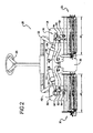
- Figure 2 is a simplified front plan view of the turf maintenance vehicle of Figure 1 with various components removed and with a first pair of turf maintenance implements having a first width coupled thereto with the universal yoke;
- Figure 3 is a simplified front plan view of the turf maintenance vehicle of Figure 1 with various components removed and with a second pair of turf maintenance implements having a second width coupled thereto with the universal yoke;
- Figure 4 is a simplified fragmented perspective view of the turf maintenance vehicle of Figure 3 with additional components removed for clarity and with the turf maintenance implements in a service position;
- Figures 5 and 6 are respective fragmented assembly views of the respective front right and front left lift systems for the turf maintenance implements for the turf maintenance vehicle of Figure 1 ;
- Figure 7A and 7B are enlarged front plan views of the universal yoke utilized in the turf maintenance vehicle of Figure 1 in two different operating positions for coupling turf maintenance implements of differing widths to the turf maintenance vehicle;
- Figure 8 is a perspective view of an alternate universal yoke according to the present teachings.
- Figure 9 is an assembly view of another alternate universal yoke according to the present teachings having two pivot arms operable to be installed simultaneously;
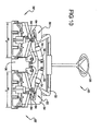
- Figure 10 is a view similar to Figure 3 wherein the turf maintenance implement is a rotary deck mower implement.
- FIG. 1 shows a turf maintenance vehicle assembly 20, in this case in the form of a riding greens mower, including a frame 22 supporting a seat 24 operable to support a passenger, a steering device 26, such as a steering wheel, and a plurality of turf maintenance implements, such as cutting units, 28, 30, 32.
- a turf maintenance vehicle assembly 20 in this case in the form of a riding greens mower, including a frame 22 supporting a seat 24 operable to support a passenger, a steering device 26, such as a steering wheel, and a plurality of turf maintenance implements, such as cutting units, 28, 30, 32.
- Front wheels 34, 36 and rear wheel 38 are rotatably connected to frame 22 and used to propel and/or steer mower assembly 20.
- Power unit 39 is connected to and supported by frame 22.
- Power unit 39 provides power to rotate one or more of wheels 34, 36, 38.
- Power unit 39 may supply power to electric motors to drive various wheels, may provide power to a hydraulic pump outputting pressurized hydraulic fluid, or may drive various wheels directly or indirectly using a mechanical transmission, by way of non-limiting example.
- pressurized hydraulic fluid the fluid drives a hydraulic motor(s) at the driven wheel(s).
- a speed control device (not shown), such as a foot-controlled pedal, is provided to control a forward or reverse speed of mower assembly 20.
- Power unit 39 can also be coupled to a plurality of motors 40, 44, each connected to one of the turf maintenance implements 28, 32, respectively (the motor for turf maintenance implement 30 is not shown), shown ins various embodiments as reel and rotary mowers or cutting units. Power unit 39 may provide electrical energy to electric motors or, alternatively, may provide pressurized hydraulic fluid to hydraulic motors to provide the rotating drive force to operate turf maintenance implements 28, 30, 32.
- FIGS 1-7 details of the coupling of front turf maintenance implements 28, 30 to mower assembly 20 with universal attachment assemblies 50 according to the present teachings are shown.
- turf maintenance implements 28, 30 each have a first width W 1
- front left and right turf maintenance implements 128, 130 each have a second width W 2 which is less than first width W 1 .
- first width W 1 can be about 22 inches
- second width W 2 can be about 18 inches.
- Attachment assembly 50 enables turf maintenance implements of either width W 1 or width W 2 to be quickly and easily attached to mower assembly 20 and be oriented in the proper position for operation.
- the first group of turf maintenance implements 28, 30 can be wider and used for cutting fairways and flat greens.
- the second set of turf maintenance implements 128, 130 having a smaller second width W 2 can be attached to mower assembly 20 for operation on these surfaces.
- the ability to easily and quickly change between turf maintenance implements of varying widths can increase productivity and efficiency along with reducing the manpower required to maintain a turf surface, such as a golf course.
- Lift systems 52 include a lift arm weldment 54 which is pivotally coupled to frame 22.
- An actuator 56 such as an electric or hydraulic actuator, is coupled to an end of lift arm 54.
- Actuator 56 is operable to cause lift arm 54 to rotate relative to frame 22 to raise and lower a turf maintenance implement coupled thereto.
- one end of actuator 56 is pivotally coupled to frame 22, while the other end of actuator 56 is pivotally coupled to an end of lift arm 54. Extension and retraction of actuator 56 can thereby cause lift arm 54 to rotate relative to frame 22 to selectively raise and lower a turf maintenance implement coupled thereto by attachment assembly 50.
- Attachment assembly 50 includes a connecting arm 60 that is rotatably received in and extends through a sleeve 62 of lift arm 54. Connecting arm 60 can rotate relative to lift arm 54 to allow the attached turf maintenance implement to pivot relative to mower assembly 20 and accommodate undulating surfaces.
- Connecting arm 60 includes a connecting sleeve 64 on an end thereof.
- Connecting sleeve 64 includes an opening 65 that extends entirely therethrough and can be generally perpendicular to the elongated main body of connecting arm 60.
- Connecting sleeve 64 is operable to receive a yoke member 66 therein. Yoke member 66 can be received in either end 64a, 64b of connecting sleeve 64.
- Yoke member 66 includes an insertion extension 68 that is dimensioned to be received in opening 65 through either end 64a, 64b of connecting sleeve 64.
- Insertion extension 68 includes a shoulder 70 that limits the distance insertion extension 68 can be inserted into opening 65 in connecting sleeve 64.
- Shoulder 70 can include a plurality of notches 72 therein.
- ends 64a, 64b of connecting sleeve 64 can also include a plurality of notches 74 that are complementary to notches 72. The engagement of notches 72 on yoke member 66 with notches 74 on connecting sleeve 64 prevents relative rotation therebetween, as described below.
- Yoke member 66 includes a receiving sleeve 76 with an opening 78 extending all the way therethrough from a first end 80 to a second end 82.
- Receiving sleeve 76 can be generally perpendicular to insertion extension 68.
- Opening 78 in receiving sleeve 76 is dimensioned to receive a connecting component 84 of a turf maintenance implement.
- First end 80 of receiving sleeve 76 includes a pair of opposed notches 86. Notches 86 can be generally V-shaped. Second end 82 of receiving sleeve 76 can be generally flat.
- a cap 90 with opposed openings 92 extending through the sidewall and a locking pin 94 can be used to secure a turf maintenance implement to yoke member 66.
- Locking pin 94 is configured to extend through openings 92 in cap 90 and through an opening 85 in connecting component 84 of the turf maintenance implement to couple the turf maintenance implement to yoke member 66.
- Clip 95 can prevent locking pin 94 from being removed from cap 90 and connecting component 84 of the turf maintenance implement.
- Locking pin 94 can reside within notches 86, thereby preventing the turf maintenance implement secured to yoke member 66 from falling out of yoke member 66.
- Cap 90 can prevent debris and other contaminants from entering into opening 78 in yoke member 66.
- Yoke member 66 is secured to connecting arm 60 with a bolt 96 and washer 98.
- Bolt 96 is threaded and is received in a complementary threaded bore in the end of insertion extension 68.
- the engagement of notches 72, 74 prevents relative rotation between connecting arm 60 and yoke member 66.
- FIG. 7A and 7B the ability of yoke member 66 to be attached to connecting arm 60 on either end 64a, 64b of connecting sleeve 64 is illustrated.
- insertion extension 68 of yoke member 66 can be inserted into connecting sleeve 64 through end 64a.
- Bolt 96 and washer 98 can engage the other end 64b of connecting sleeve 64 to secure yoke member 66 to connecting sleeve 64.
- yoke member 66 can be inserted into connecting sleeve 64 through end 64b.
- Bolt 96 and washer 98 can engage with end 64a of connecting sleeve 64 to secure yoke member 66 to connecting sleeve 64 of connecting arm 60.
- the attachment assembly 50 according to the present teachings enables yoke member 66 to be attached to either end 64a, 64b of connecting sleeve 64.
- yoke member 66 can be disposed on either side of connecting arm 60. This allows for the centerline 99 of yoke member 66 to be offset from a vertical centerline 100 of connecting sleeve 64 a distance D either to the right or the left. This capability enables a transverse change in the position of centerline 99 of yoke member 66 a total distance of 2 times D (2 x D).
- an attachment assembly 50 provides a universal fit-up wherein yoke member 66 can be connected to either end 64a, 64b of connecting sleeve 64 of connecting arm 60.
- This capability allows attachment assembly 50 to be a universal attachment assembly wherein implements of differing widths, such as widths W 1 , W 2 , can be coupled to mower assembly 20 in a desired position to accommodate differing turf care needs.
- the ability to attach yoke member 66 to either end 64a, 64b of connecting sleeve 64 accommodates the differing widths W 1 , W 2 of the associated turf maintenance implement. For example, as shown in Figures 1 and 2 , turf maintenance implements 28, 30 having width W 1 can be attached to mower assembly 20 via attachment assembly 50.
- yoke members 66 are coupled to the outboard sides of connecting sleeves 64 of connecting arms 60.
- yoke members 66 can be coupled to the inboard ends of connecting sleeves 64 of connecting arms 60.
- the distance D by which yoke member 66 is offset from connecting sleeve 64 can be selected to be one half of the difference in widths (W 1 -W 2 ) of the different turf maintenance implements by way of non-limiting example.
- the ability to attach turf maintenance implements of differing widths by coupling the yoke members 66 to either the outboard or inboard ends of connecting sleeves 64 allows the turf maintenance implements to be properly aligned relative to mower assembly 20 for their associated widths and also with the rear turf maintenance implement (shown in Figure 1 only). In this manner, a user of mower assembly 20 can switch between turf maintenance implements of varying widths while still using the same mower assembly 20.
- This ability allows the user to quickly switch between different turf maintenance implements to perform differing tasks. For example, the user can use turf maintenance implements of one width for relatively flat greens and fairways while using turf maintenance implements of a smaller width for undulating greens.
- the ability to easily and quickly switch between turf maintenance implements of different widths reduces the time and labor costs associated with turf care.
- attachment assembly 50 also enables the positioning of turf maintenance implements in a service position.
- notches 72 in yoke member 66 engage with notches 74 of connecting sleeve 64 to prevent relative rotation therebetween.
- the location of and spacing of notches 72, 74 can be set to allow yoke member 66 to be disposed in specific orientations relative to connecting sleeve 64.
- yoke member 66 can be secured to connecting sleeve 64 such that it extends generally vertically, as shown in Figures 1-3 .
- yoke member 66 When it is desired to service the attached turf maintenance implement, yoke member 66 can be detached from connecting sleeve 64 such that the associated notches 72, 74 are disengaged and rotated relative thereto to a generally horizontal orientation, as shown in Figure 4 . Yoke member 66 can then be re-secured to connecting sleeve 64 with bolt 96 and washer 98. In this position, yoke member 66 and attachment assembly 50 can hold the associated turf maintenance implement in a service position. For example, such service position may be desirable to facilitate the sharpening of the turf maintenance implements, making adjustments, replacing parts, or other service procedures. The spacing and positioning of notches 72, 74 can be set to provide desired orientations between yoke member 66 and connecting sleeve 64.
- an attachment assembly 50 according to the present teachings can advantageously facilitate the attachment of a turf maintenance implement to mower assembly 20 in both an operative position and a service position.
- attachment assembly 150 is similar to attachment assembly 50 described above. Accordingly, only the main differences will be described and it should be appreciated that not all details of attachment assembly 150 are described herein.
- ends 164a, 164b of connecting sleeve 164 do not contain notches. Rather, these ends are relatively flat.
- insertion extension 168 includes a plurality of through openings 169 that are radially spaced around insertion extension 168.
- connecting sleeve 164 includes a vertically extending through opening 171 that can align with through openings 169 on insertion extension 168.
- a locking pin 173 can be inserted through openings 171, 169 in connecting sleeve 164 and yoke member 166, respectively, and secured in place with a clip 175. Locking pin 173 can thereby prevent relative rotation between yoke member 166 and connecting sleeve 164 while also preventing removal of yoke member 166 from connecting sleeve 164.
- yoke member 166 can be inserted into connecting sleeve 164 through either end 164a, 164b to thereby allow a universal connection and ability to attach turf maintenance implements of differing widths.
- attachment assembly 150 enables the turf maintenance implements secured therewith to be disposed in an operating position and in a service position, as discussed above.
- Attachment assembly 250 is similar to attachment assembly 50 described above. Accordingly, only the main differences will be described and it should be appreciated that not all details of attachment assembly 250 are described herein. Attachment assembly 250 again allows attachment of a yoke member 266 to either end 264a, 264b of a connecting sleeve 264. In addition, attachment assembly 250 enables two separate yoke members 266 to be secured to the opposite ends of connecting sleeve 264 at the same time. In attachment assembly 250, insertion extensions 268 include a recessed annular groove 281 that generally aligns with an opening 283 in connecting sleeve 264 when inserted therein.
- Opening 283 can be threaded and can be dimensioned to receive a threaded member 285, such as a bolt or set screw.
- Threaded member 285 can be dimensioned to be received in groove 281 of insertion extension 268 when disposed in connecting sleeve 264. Threaded member 285 can thereby secure yoke member 266 to connecting sleeve 64 and prevent removal therefrom.
- yoke member 266 includes a plurality of notches 272 that engage with notches 274 on the ends of connecting sleeve 264.
- two yoke members 266 can be simultaneously secured to connecting sleeve 264 with threaded members 285, while the engagement of notches 272, 274 prevents relative rotation. Notches 272, 274 allow the turf maintenance implements to be attached to mower assembly 20 in an operative position and in a service position, as described above.
- the simultaneously retention of two yoke members 266 may facilitate quicker and easier changeover of turf maintenance implements of differing widths.
- attachment assemblies 50, 150, 250 can advantageously allow the attachment of turf maintenance implements of varying widths to mower assembly 20, while providing the desired orientation of the turf maintenance implements relative to mower assembly 20.
- the ability to attach the same yoke member 66, 166, 266 to either end of an associated connecting sleeve 64, 164, 264 facilitates the easy installation of turf maintenance implements of varying widths.
- the connections between yoke members 66, 166, 266 and the associated connecting sleeves 64, 164, 264 allow for the easy relocation to either end of the connecting sleeve.
- the attachment assemblies 50, 150, 250 also enable turf maintenance implements to be attached to mower assembly 20 in both an operative position and a service position.
- turf maintenance implements other than cutting units can be attached to mower assembly 20 with the attachment assemblies according to the present teachings.
- the turf maintenance implements can include groomers, power brushes, vertical-cutting accessories, and/or combinations thereof.
- attachment assembly 50 can be used to secure a rotary type turf maintenance implement 28', 30', 32' in the form of rotary mowing decks. It should be appreciated, however, that other types of rotary turf maintenance implements can also be used with the attachment assemblies according to the present teachings. Additionally, the number and locations of the attachment assemblies can also vary.
- an attachment assembly can be utilized to secure a rear turf maintenance implement to mower assembly 20, by way of non-limiting example.
- attachment assemblies 50, 150, 250 can be intermixed with one another to achieve a desired operational capability for the attachment assembly.
- attachment assemblies 50, 150 can be dimensioned to allow the simultaneous attachment of two yoke members thereto, if desired.
- attachment assemblies 50, 250 can be modified to utilize a locking pin and clip to prevent relative rotation, if desired. Accordingly, such alteration and changes should be regarded as being within the scope of the present teachings.
Landscapes
- Life Sciences & Earth Sciences (AREA)
- Environmental Sciences (AREA)
- Harvester Elements (AREA)
Abstract
Description
- The present teachings relate to turf maintenance vehicles and, more particularly, to a turf maintenance vehicle and a yoke assembly allowing the interchanging of turf maintenance implements of varying widths.
- The statements in this section merely provide background information related to the present teachings and may not constitute prior art.
- Turf maintenance vehicles, such as riding greens mowers, are typically configured with 22-inch turf maintenance implements, with no availability of coupling 18-inch turf maintenance implements thereto. When a surface being mowed, such as a golf course greens, has an undulated surface, the preferred turf maintenance implement width is 18 inches. Due to the unavailability of coupling the 18-inch turf maintenance implement to the riding greens mower, a user must utilize a walking mower which utilizes the 18-inch turf maintenance implement. The requirement to use the walking mower instead of the riding greens mower increases the man power/labor costs to mow the greens. Thus, it would be advantageous to have the ability to install turf maintenance implements of varying widths onto a riding greens mower.
- A universal attachment assembly according to the present teachings can allow for coupling of turf maintenance implements of varying widths to a turf maintenance vehicle, such as a riding greens mower by way of non-limiting example. The attachment assembly allows for the use of a yoke member that can be coupled to a coupling member in various positions. The various positions can correspond to accommodating turf maintenance implements of varying widths. This capability can facilitate the changing of turf maintenance implements of varying widths to perform differing tasks. The attachment assembly allows the turf maintenance implements of varying widths to be attached in an orientation that accommodates the differing widths and provides proper alignment on the turf maintenance vehicle and/or with other turf maintenance implements also mounted to the turf maintenance vehicle. Additionally, the attachment assembly can allow the turf maintenance implements to be positioned in different orientations to allow for operation of the turf maintenance implement and to allow for service of the turf maintenance implement. This capability can facilitate the servicing of the turf maintenance implement.
- An attachment assembly for a turf maintenance vehicle according to the present teachings can include a yoke member and a coupling member. The yoke member can have first and second connecting features with the first connecting feature operable to connect the yoke member to a turf maintenance implement. The coupling member is operable to couple the yoke member to a frame assembly. The coupling member can include a first attachment feature that can be coupled to the frame assembly and a second attachment feature that engages with the second connecting feature, thereby coupling the yoke member to the coupling member. The second attachment feature allows the yoke member to be coupled to the coupling member in at least two positions. A first one of the at least two positions corresponds to the yoke member being in a first orientation relative to the coupling member, while a second one of the at least two positions corresponds to the yoke member being in a second orientation relative to the coupling member. The first and second orientations are different.
- In another aspect, a turf maintenance vehicle according to the present teachings includes a frame assembly, a power unit coupled to the frame assembly, at least two wheels coupled to the frame assembly, and an attachment assembly. The attachment assembly is operable to couple turf maintenance implements of varying widths to the frame assembly.
- In yet another aspect of the present teachings, an attachment assembly for a turf maintenance vehicle includes a yoke member and a coupling member. The yoke member has first and second connecting features with the first connecting feature operable to connect the yoke member to a turf maintenance implement. The coupling member couples the yoke member to a turf maintenance vehicle frame assembly with a first attachment feature. The coupling member can include a second attachment feature that engages with the second connecting feature, thereby coupling the yoke member to the coupling member. The second attachment feature and the second connecting feature allow the yoke member to be coupled to the coupling member at two different locations on the coupling member and in at least two different orientations at each of the two locations.
- Further areas of applicability will become apparent from the description provided herein. It should be understood that the description and specific examples are intended for purposes of illustration only and are not intended to limit the scope of the present teachings.
- The drawings described herein are for illustration purposes only and are not intended to limit the scope of the present disclosure in any way.
-
Figure 1 is a perspective view of a turf maintenance vehicle utilizing the universal yoke according to the present teachings; -
Figure 2 is a simplified front plan view of the turf maintenance vehicle ofFigure 1 with various components removed and with a first pair of turf maintenance implements having a first width coupled thereto with the universal yoke; -
Figure 3 is a simplified front plan view of the turf maintenance vehicle ofFigure 1 with various components removed and with a second pair of turf maintenance implements having a second width coupled thereto with the universal yoke; -
Figure 4 is a simplified fragmented perspective view of the turf maintenance vehicle ofFigure 3 with additional components removed for clarity and with the turf maintenance implements in a service position; -
Figures 5 and6 are respective fragmented assembly views of the respective front right and front left lift systems for the turf maintenance implements for the turf maintenance vehicle ofFigure 1 ; -
Figure 7A and 7B are enlarged front plan views of the universal yoke utilized in the turf maintenance vehicle ofFigure 1 in two different operating positions for coupling turf maintenance implements of differing widths to the turf maintenance vehicle; -
Figure 8 is a perspective view of an alternate universal yoke according to the present teachings; -
Figure 9 is an assembly view of another alternate universal yoke according to the present teachings having two pivot arms operable to be installed simultaneously; and -
Figure 10 is a view similar toFigure 3 wherein the turf maintenance implement is a rotary deck mower implement. - The following description is merely exemplary in nature and is not intended to limit the present teachings, applications, or uses. It should be understood that throughout the drawings, corresponding reference numerals indicate like or corresponding parts and features (e.g., 20, 120, 220, etc.).
-
Figure 1 shows a turfmaintenance vehicle assembly 20, in this case in the form of a riding greens mower, including aframe 22 supporting aseat 24 operable to support a passenger, asteering device 26, such as a steering wheel, and a plurality of turf maintenance implements, such as cutting units, 28, 30, 32. It should be noted that while the present teachings will be described with respect to a riding greens mower, one skilled in the art will recognize that teachings described herein are equally applicable to any walking and/or riding turf maintenance vehicle for which it may be generally desirable to change implements.Front wheels rear wheel 38 are rotatably connected toframe 22 and used to propel and/orsteer mower assembly 20. Power unit 39 is connected to and supported byframe 22. Power unit 39 provides power to rotate one or more ofwheels mower assembly 20. - Power unit 39 can also be coupled to a plurality of
motors 40, 44, each connected to one of theturf maintenance implements 28, 32, respectively (the motor forturf maintenance implement 30 is not shown), shown ins various embodiments as reel and rotary mowers or cutting units. Power unit 39 may provide electrical energy to electric motors or, alternatively, may provide pressurized hydraulic fluid to hydraulic motors to provide the rotating drive force to operateturf maintenance implements - Referring now to
Figures 1-7 , details of the coupling of front turf maintenance implements 28, 30 tomower assembly 20 withuniversal attachment assemblies 50 according to the present teachings are shown. InFigures 1 and2 , turf maintenance implements 28, 30 each have a first width W1, while inFigures 3 and4 , front left and rightturf maintenance implements Attachment assembly 50 enables turf maintenance implements of either width W1 or width W2 to be quickly and easily attached tomower assembly 20 and be oriented in the proper position for operation. For example, the first group of turf maintenance implements 28, 30 can be wider and used for cutting fairways and flat greens. When encountering undulating greens, however, the second set of turf maintenance implements 128, 130 having a smaller second width W2 can be attached tomower assembly 20 for operation on these surfaces. The ability to easily and quickly change between turf maintenance implements of varying widths can increase productivity and efficiency along with reducing the manpower required to maintain a turf surface, such as a golf course. - Referring now to
Figures 5-7 , details of the respective right andleft lift systems 52 having universal attachment assemblies 50 according to the present teachings are shown.Lift systems 52 include alift arm weldment 54 which is pivotally coupled toframe 22. Anactuator 56, such as an electric or hydraulic actuator, is coupled to an end oflift arm 54.Actuator 56 is operable to causelift arm 54 to rotate relative to frame 22 to raise and lower a turf maintenance implement coupled thereto. Specifically, one end ofactuator 56 is pivotally coupled toframe 22, while the other end ofactuator 56 is pivotally coupled to an end oflift arm 54. Extension and retraction ofactuator 56 can thereby causelift arm 54 to rotate relative to frame 22 to selectively raise and lower a turf maintenance implement coupled thereto byattachment assembly 50. -
Attachment assembly 50 includes a connectingarm 60 that is rotatably received in and extends through asleeve 62 oflift arm 54. Connectingarm 60 can rotate relative to liftarm 54 to allow the attached turf maintenance implement to pivot relative tomower assembly 20 and accommodate undulating surfaces. Connectingarm 60 includes a connectingsleeve 64 on an end thereof. Connectingsleeve 64 includes anopening 65 that extends entirely therethrough and can be generally perpendicular to the elongated main body of connectingarm 60. Connectingsleeve 64 is operable to receive ayoke member 66 therein.Yoke member 66 can be received in eitherend sleeve 64.Yoke member 66 includes aninsertion extension 68 that is dimensioned to be received in opening 65 through eitherend sleeve 64.Insertion extension 68 includes ashoulder 70 that limits thedistance insertion extension 68 can be inserted into opening 65 in connectingsleeve 64.Shoulder 70 can include a plurality ofnotches 72 therein. Similarly, ends 64a, 64b of connectingsleeve 64 can also include a plurality ofnotches 74 that are complementary tonotches 72. The engagement ofnotches 72 onyoke member 66 withnotches 74 on connectingsleeve 64 prevents relative rotation therebetween, as described below. -
Yoke member 66 includes a receivingsleeve 76 with anopening 78 extending all the way therethrough from afirst end 80 to asecond end 82. Receivingsleeve 76 can be generally perpendicular toinsertion extension 68.Opening 78 in receivingsleeve 76 is dimensioned to receive a connectingcomponent 84 of a turf maintenance implement. First end 80 of receivingsleeve 76 includes a pair ofopposed notches 86.Notches 86 can be generally V-shaped.Second end 82 of receivingsleeve 76 can be generally flat. - A
cap 90 withopposed openings 92 extending through the sidewall and alocking pin 94 can be used to secure a turf maintenance implement toyoke member 66. Lockingpin 94 is configured to extend throughopenings 92 incap 90 and through anopening 85 in connectingcomponent 84 of the turf maintenance implement to couple the turf maintenance implement toyoke member 66.Clip 95 can prevent lockingpin 94 from being removed fromcap 90 and connectingcomponent 84 of the turf maintenance implement. Lockingpin 94 can reside withinnotches 86, thereby preventing the turf maintenance implement secured toyoke member 66 from falling out ofyoke member 66.Cap 90 can prevent debris and other contaminants from entering into opening 78 inyoke member 66. -
Yoke member 66 is secured to connectingarm 60 with abolt 96 andwasher 98.Bolt 96 is threaded and is received in a complementary threaded bore in the end ofinsertion extension 68. The engagement betweenbolt 96 and the threaded bore in the end ofinsertion extension 68, along with the engagement betweenwasher 98 and an end of connectingsleeve 64, preventsyoke member 66 from being removed from connectingsleeve 64 and connectingarm 60. The engagement ofnotches arm 60 andyoke member 66. - Referring now to
Figures 7A and 7B , the ability ofyoke member 66 to be attached to connectingarm 60 on eitherend sleeve 64 is illustrated. As shown inFigure 7A ,insertion extension 68 ofyoke member 66 can be inserted into connectingsleeve 64 throughend 64a.Bolt 96 andwasher 98 can engage theother end 64b of connectingsleeve 64 to secureyoke member 66 to connectingsleeve 64. Alternatively, as shown inFigure 7B ,yoke member 66 can be inserted into connectingsleeve 64 throughend 64b.Bolt 96 andwasher 98 can engage withend 64a of connectingsleeve 64 to secureyoke member 66 to connectingsleeve 64 of connectingarm 60. Thus, theattachment assembly 50 according to the present teachings enablesyoke member 66 to be attached to eitherend sleeve 64. As a result of this capability,yoke member 66 can be disposed on either side of connectingarm 60. This allows for thecenterline 99 ofyoke member 66 to be offset from avertical centerline 100 of connectingsleeve 64 a distance D either to the right or the left. This capability enables a transverse change in the position ofcenterline 99 of yoke member 66 a total distance of 2 times D (2 x D). - Thus, an
attachment assembly 50 according to the present teachings provides a universal fit-up whereinyoke member 66 can be connected to eitherend sleeve 64 of connectingarm 60. This capability allowsattachment assembly 50 to be a universal attachment assembly wherein implements of differing widths, such as widths W1, W2, can be coupled tomower assembly 20 in a desired position to accommodate differing turf care needs. The ability to attachyoke member 66 to eitherend sleeve 64 accommodates the differing widths W1, W2 of the associated turf maintenance implement. For example, as shown inFigures 1 and2 , turf maintenance implements 28, 30 having width W1 can be attached tomower assembly 20 viaattachment assembly 50. In this case,yoke members 66 are coupled to the outboard sides of connectingsleeves 64 of connectingarms 60. When it is desired to attach turf maintenance implements 128, 130 having a smaller width W2, as shown inFigures 3 and4 ,yoke members 66 can be coupled to the inboard ends of connectingsleeves 64 of connectingarms 60. The distance D by whichyoke member 66 is offset from connectingsleeve 64 can be selected to be one half of the difference in widths (W1-W2) of the different turf maintenance implements by way of non-limiting example. The ability to attach turf maintenance implements of differing widths by coupling theyoke members 66 to either the outboard or inboard ends of connectingsleeves 64 allows the turf maintenance implements to be properly aligned relative tomower assembly 20 for their associated widths and also with the rear turf maintenance implement (shown inFigure 1 only). In this manner, a user ofmower assembly 20 can switch between turf maintenance implements of varying widths while still using thesame mower assembly 20. This ability allows the user to quickly switch between different turf maintenance implements to perform differing tasks. For example, the user can use turf maintenance implements of one width for relatively flat greens and fairways while using turf maintenance implements of a smaller width for undulating greens. The ability to easily and quickly switch between turf maintenance implements of different widths reduces the time and labor costs associated with turf care. - Referring now to
Figure 4 ,attachment assembly 50 also enables the positioning of turf maintenance implements in a service position. Specifically,notches 72 inyoke member 66 engage withnotches 74 of connectingsleeve 64 to prevent relative rotation therebetween. The location of and spacing ofnotches yoke member 66 to be disposed in specific orientations relative to connectingsleeve 64. When it is desired to utilize the turf maintenance implements for their intended function,yoke member 66 can be secured to connectingsleeve 64 such that it extends generally vertically, as shown inFigures 1-3 . When it is desired to service the attached turf maintenance implement,yoke member 66 can be detached from connectingsleeve 64 such that the associatednotches Figure 4 .Yoke member 66 can then be re-secured to connectingsleeve 64 withbolt 96 andwasher 98. In this position,yoke member 66 andattachment assembly 50 can hold the associated turf maintenance implement in a service position. For example, such service position may be desirable to facilitate the sharpening of the turf maintenance implements, making adjustments, replacing parts, or other service procedures. The spacing and positioning ofnotches yoke member 66 and connectingsleeve 64. Thus, anattachment assembly 50 according to the present teachings can advantageously facilitate the attachment of a turf maintenance implement tomower assembly 20 in both an operative position and a service position. - Referring now to
Figure 8 , an alternate embodiment of auniversal attachment assembly 150 according to the present teachings is shown.Attachment assembly 150 is similar toattachment assembly 50 described above. Accordingly, only the main differences will be described and it should be appreciated that not all details ofattachment assembly 150 are described herein. Inattachment assembly 150, ends 164a, 164b of connectingsleeve 164 do not contain notches. Rather, these ends are relatively flat. To prevent relative rotation betweenyoke member 166 and connectingsleeve 164,insertion extension 168 includes a plurality of throughopenings 169 that are radially spaced aroundinsertion extension 168. Additionally, connectingsleeve 164 includes a vertically extending throughopening 171 that can align with throughopenings 169 oninsertion extension 168. A lockingpin 173 can be inserted throughopenings sleeve 164 andyoke member 166, respectively, and secured in place with aclip 175. Lockingpin 173 can thereby prevent relative rotation betweenyoke member 166 and connectingsleeve 164 while also preventing removal ofyoke member 166 from connectingsleeve 164. Again,yoke member 166 can be inserted into connectingsleeve 164 through eitherend 164a, 164b to thereby allow a universal connection and ability to attach turf maintenance implements of differing widths. The plurality ofopenings 169 ininsertion extension 168 allowsyoke member 166 to be secured to connectingsleeve 164 in a variety of orientations, such as with receivingsleeve 176 vertically or horizontally oriented. In this manner,attachment assembly 150 enables the turf maintenance implements secured therewith to be disposed in an operating position and in a service position, as discussed above. - Referring now to
Figure 9 , another alternate embodiment of auniversal attachment assembly 250 according to the present teachings is shown.Attachment assembly 250 is similar toattachment assembly 50 described above. Accordingly, only the main differences will be described and it should be appreciated that not all details ofattachment assembly 250 are described herein.Attachment assembly 250 again allows attachment of ayoke member 266 to eitherend 264a, 264b of a connectingsleeve 264. In addition,attachment assembly 250 enables twoseparate yoke members 266 to be secured to the opposite ends of connectingsleeve 264 at the same time. Inattachment assembly 250,insertion extensions 268 include a recessedannular groove 281 that generally aligns with anopening 283 in connectingsleeve 264 when inserted therein. Opening 283 can be threaded and can be dimensioned to receive a threadedmember 285, such as a bolt or set screw. Threadedmember 285 can be dimensioned to be received ingroove 281 ofinsertion extension 268 when disposed in connectingsleeve 264. Threadedmember 285 can thereby secureyoke member 266 to connectingsleeve 64 and prevent removal therefrom. To prevent relative rotation,yoke member 266 includes a plurality ofnotches 272 that engage withnotches 274 on the ends of connectingsleeve 264. Thus, inattachment assembly 250, twoyoke members 266 can be simultaneously secured to connectingsleeve 264 with threadedmembers 285, while the engagement ofnotches Notches mower assembly 20 in an operative position and in a service position, as described above. The simultaneously retention of twoyoke members 266 may facilitate quicker and easier changeover of turf maintenance implements of differing widths. - Thus, it should be appreciated that
attachment assemblies mower assembly 20, while providing the desired orientation of the turf maintenance implements relative tomower assembly 20. The ability to attach thesame yoke member sleeve yoke members sleeves attachment assemblies mower assembly 20 in both an operative position and a service position. - While the present teachings have been described with reference to specific examples and illustrations, it should be appreciated that changes can be made without departing from the spirit and scope of the present teachings. For example, turf maintenance implements other than cutting units can be attached to
mower assembly 20 with the attachment assemblies according to the present teachings. By way of non-limiting example, the turf maintenance implements can include groomers, power brushes, vertical-cutting accessories, and/or combinations thereof. Furthermore, as shown inFigure 10 ,attachment assembly 50 can be used to secure a rotary type turf maintenance implement 28', 30', 32' in the form of rotary mowing decks. It should be appreciated, however, that other types of rotary turf maintenance implements can also be used with the attachment assemblies according to the present teachings. Additionally, the number and locations of the attachment assemblies can also vary. For example, an attachment assembly according to the present teachings can be utilized to secure a rear turf maintenance implement tomower assembly 20, by way of non-limiting example. Additionally, it should be appreciated that the various features disclosed inattachment assemblies attachment assemblies attachment assemblies - The abstract for this application is repeated below to form part of this specification:-
- A universal attachment assembly is operable to couple turf maintenance implements of varying widths to a turf maintenance vehicle. The attachment assembly can include a yoke member that can be attached to a coupling member in various locations. The different locations can accommodate varying widths of the turf maintenance implements that are coupled to the turf maintenance vehicle with the yoke member. The yoke member can also be positioned in different orientations relative to the coupling member in both the first and second positions. The different orientations can correspond to an operating position and a servicing position for the turf maintenance implement.
Claims (22)
- An attachment assembly for a turf maintenance vehicle, the attachment assembly comprising:a yoke member having first and second connecting features, the first connecting feature operable to connect the yoke member to a turf maintenance implement; anda coupling member operable to couple the yoke member to a frame assembly, the coupling member including a first attachment feature that can be coupled to a frame assembly and a second attachment feature engaging with the second connecting feature thereby coupling the yoke member to the coupling member, the second attachment feature allowing the yoke member to be coupled to the coupling member in at least two positions, a first one of the at least two positions corresponding to the yoke member being in a first orientation relative to the coupling member and a second one of the at least two positions corresponding to the yoke member being in a second orientation relative to the coupling member, the second orientation being different than the first orientation.
- The attachment assembly of claim 1, wherein the yoke member is disposed on a first side of the coupling member when in the first position and is disposed on a second side of the coupling member when in the second position.
- The attachment assembly of claim 2, wherein the first and second sides are opposing sides, the second attachment feature includes an opening in the coupling member that extends between the first and second sides, the second connecting feature includes an insertion member that can be received in the opening, the first position corresponds to the insertion member being inserted into the opening through the first side, and the second position corresponds to the insertion member being inserted into the opening through the second side.
- The attachment assembly of claim 3, further comprising a retainer retaining the insertion member in the opening in the coupling member.
- The attachment assembly of claim 4, wherein an end of the insertion member includes a threaded bore and the retainer includes a threaded fastener that engages with the threaded bore and retains the yoke member secured to the coupling member.
- The attachment assembly of claim 4, wherein the insertion member includes a through opening and the retainer includes a pin that extends through the coupling member and through the opening in the insertion member thereby retaining the yoke member secured to the coupling member.
- The attachment assembly of claim 4, wherein the insertion member includes an annular groove and the retainer includes an elongated member that extends through a portion of the coupling member and engages with the groove thereby retaining the yoke member secured to the coupling member.
- The attachment assembly of claim 4, wherein the retainer prevents the yoke member from being uncoupled from the coupling member while allowing relative rotation therebetween.
- The attachment assembly of claim 1, further comprising a retaining member engaging with the yoke member and with the coupling member, the retaining member securing the yoke member to the coupling member.
- The attachment assembly of claim of claim 9, wherein the retaining member prevents relative rotation between the yoke member and the coupling member.
- The attachment assembly of claim 10, wherein the retaining member allows the yoke member to be disposed in multiple discrete positions relative to the coupling member.
- The attachment assembly of claim 1, wherein the yoke member is rotated relative to the coupling member to move between the first and second positions.
- The attachment assembly of claim 12, wherein the first position corresponds to an attached turf maintenance implement being in an operative position and the second position corresponds to an attached turf maintenance implement being in a serviceable position.
- The attachment assembly of claim 1, wherein the yoke member is offset from the coupling member in a first direction when in the first position, the yoke member is offset from the coupling member in a second direction when in the second position, and the second direction is opposite the first direction.
- The attachment assembly of claim 1, wherein a centerline of the first connecting feature of the yoke member is offset from a reference line of the coupling member a first and second distance when in the respective first and second positions, and the first and second distances are substantially the same.
- The attachment assembly of claim 1, wherein the second attachment feature and the second connecting feature include complementary teeth that engage and prevent relative rotation between the yoke member and the coupling member when in either one of the first and second positions.
- The attachment assembly of claim 1, wherein the first connecting feature includes a bore extending through the yoke member and operable to receive a component of a turf maintenance implement to retain the turf maintenance implement to the yoke member.
- The attachment assembly of claim 1, wherein the yoke member can be rotated between third and fourth positions when in either one of the first and second positions, the third and fourth positions being different positions relative to the coupling member.
- The attachment assembly of claim 1, wherein the coupling member can simultaneously receive and retain two yoke members with one yoke member in each of the at least two positions.
- A turf maintenance vehicle comprising:a frame assembly;a power unit coupled to the frame assembly;at least two wheels coupled to the frame assembly; andan attachment assembly in accordance with any one of the preceding claims.
- The turf maintenance vehicle of claim 20, wherein engagement of the complementary teeth allow the yoke member to be disposed in multiple orientations relative to the coupling member.
- The turf maintenance vehicle of claim 20, wherein:the coupling member includes opposing first and second sides and the second attachment feature includes an opening in the coupling member that extends between the first and second sides;the second connecting feature includes an insertion member that can be received in the opening; andthe first position corresponds to the insertion member being inserted into the opening through the first side with the majority of the yoke member disposed on the first side and the second position corresponds to the insertion member being inserted into the opening through the second side with the majority of the yoke member disposed on the second side.
Applications Claiming Priority (1)
| Application Number | Priority Date | Filing Date | Title |
|---|---|---|---|
| US12/033,285 US7841158B2 (en) | 2008-02-19 | 2008-02-19 | Universal yoke assembly for a turf maintenance vehicle |
Publications (2)
| Publication Number | Publication Date |
|---|---|
| EP2092817A1 true EP2092817A1 (en) | 2009-08-26 |
| EP2092817B1 EP2092817B1 (en) | 2011-04-13 |
Family
ID=40568614
Family Applications (1)
| Application Number | Title | Priority Date | Filing Date |
|---|---|---|---|
| EP09150404A Active EP2092817B1 (en) | 2008-02-19 | 2009-01-12 | Universal yoke assembly for a turf maintenance vehicle |
Country Status (4)
| Country | Link |
|---|---|
| US (1) | US7841158B2 (en) |
| EP (1) | EP2092817B1 (en) |
| JP (1) | JP5787468B2 (en) |
| DE (1) | DE602009001011D1 (en) |
Families Citing this family (8)
| Publication number | Priority date | Publication date | Assignee | Title |
|---|---|---|---|---|
| US8544251B2 (en) * | 2008-06-27 | 2013-10-01 | The Toro Company | Reel mower with cutting units suspended by double A arm suspensions |
| USD657231S1 (en) * | 2010-07-09 | 2012-04-10 | Kristopher Paul Springer | Bracket |
| GB2494206A (en) * | 2011-09-05 | 2013-03-06 | Ransomes Jacobsen Ltd | Self-propelled grass cutting machine |
| US9027318B2 (en) * | 2012-02-07 | 2015-05-12 | IHI Shibaura Machinery Corporation | Reel lawn mower with main body, reel cutting unit, and connection structure for connecting reel cutting unit to main body such that reel cutting unit is rollable |
| WO2014203422A1 (en) * | 2013-06-19 | 2014-12-24 | ヤンマー株式会社 | Electric work vehicle |
| US10517217B2 (en) * | 2017-07-20 | 2019-12-31 | Deere & Company | Cotton picker unit lift structure |
| US10390488B2 (en) | 2017-08-08 | 2019-08-27 | Deere & Company | Triplex greensmower lift system |
| CN108575261B (en) * | 2018-03-28 | 2020-12-11 | 张习先 | Greening lawn trimming equipment based on gyroscope automatic leveling technology |
Citations (2)
| Publication number | Priority date | Publication date | Assignee | Title |
|---|---|---|---|---|
| US3514926A (en) * | 1968-10-23 | 1970-06-02 | Jacobsen Mfg Co | Leveler for a reel-type lawn mower |
| US5623817A (en) * | 1995-01-20 | 1997-04-29 | The Toro Company | Operating unit joint for turf maintenance equipment |
Family Cites Families (20)
| Publication number | Priority date | Publication date | Assignee | Title |
|---|---|---|---|---|
| US3090184A (en) * | 1961-11-08 | 1963-05-21 | George Fisanick | Hydraulic horizontal sliding action gang mower |
| JPS60119237U (en) * | 1984-01-20 | 1985-08-12 | 株式会社 神崎高級工機製作所 | Reel mower device |
| JPS60119238U (en) * | 1984-01-21 | 1985-08-12 | 株式会社 神崎高級工機製作所 | mower lifting device |
| US5069022A (en) * | 1990-09-28 | 1991-12-03 | Befco, Inc. | Gang mower apparatus |
| FR2668880B1 (en) * | 1990-11-12 | 1995-06-30 | Kuhn Sa | PROCESS FOR TRANSFORMING A HARVESTING MACHINE TO BRING IT FROM A TRANSPORT POSITION TO A WORKING POSITION, AND HARVESTING MACHINE. |
| US5343680A (en) * | 1992-09-03 | 1994-09-06 | Deere & Company | Suspension mechanism for reel mowers |
| JPH09121645A (en) * | 1995-10-31 | 1997-05-13 | Kubota Corp | Lawn mower |
| US5865016A (en) * | 1997-02-07 | 1999-02-02 | Ransomes America Corporation | Release mechanism for cutting head of a gang mower |
| JP3885338B2 (en) * | 1998-03-04 | 2007-02-21 | 井関農機株式会社 | Rotary tiller stand |
| US6131378A (en) * | 1998-03-09 | 2000-10-17 | Lees; Earl K. | Gang mower |
| US6341478B1 (en) * | 1999-06-14 | 2002-01-29 | The Toro Company | Steerable cutting unit with steerable and level lift grass catcher |
| US6237313B1 (en) * | 1999-08-13 | 2001-05-29 | Deere & Company | Grass catcher support assembly for reel mower cutting unit |
| US6412258B1 (en) * | 2000-08-31 | 2002-07-02 | Textron Inc. | Tractor-supported lawnmower having mowers movable up and down |
| IT251364Y1 (en) * | 2000-11-13 | 2003-11-19 | Rotomec Spa | MOWER WITH IMPROVED SYSTEM OF MOWING PLATES |
| CA2353030A1 (en) * | 2001-07-13 | 2003-01-13 | Willem Jager | Caster mounted reel mower |
| JP3761830B2 (en) * | 2002-04-01 | 2006-03-29 | ブイアイブイエンジニアリング株式会社 | Hand-held brush cutter |
| US7398637B1 (en) * | 2003-02-10 | 2008-07-15 | Recker Industries, Inc. | Accessory mounting system for a riding lawnmower |
| US7331166B2 (en) * | 2005-01-28 | 2008-02-19 | Deere & Company | Coupling mechanism for mower cutting units |
| US7392869B2 (en) * | 2005-11-01 | 2008-07-01 | Textron Inc. | Modular power source for riding mower |
| US7568331B2 (en) | 2005-12-21 | 2009-08-04 | Deere & Company | Extendable lift arms for trim mower |
-
2008
- 2008-02-19 US US12/033,285 patent/US7841158B2/en active Active
-
2009
- 2009-01-12 EP EP09150404A patent/EP2092817B1/en active Active
- 2009-01-12 DE DE602009001011T patent/DE602009001011D1/en active Active
- 2009-02-19 JP JP2009037174A patent/JP5787468B2/en active Active
Patent Citations (2)
| Publication number | Priority date | Publication date | Assignee | Title |
|---|---|---|---|---|
| US3514926A (en) * | 1968-10-23 | 1970-06-02 | Jacobsen Mfg Co | Leveler for a reel-type lawn mower |
| US5623817A (en) * | 1995-01-20 | 1997-04-29 | The Toro Company | Operating unit joint for turf maintenance equipment |
Also Published As
| Publication number | Publication date |
|---|---|
| DE602009001011D1 (en) | 2011-05-26 |
| JP5787468B2 (en) | 2015-09-30 |
| JP2009195230A (en) | 2009-09-03 |
| US7841158B2 (en) | 2010-11-30 |
| US20090206576A1 (en) | 2009-08-20 |
| EP2092817B1 (en) | 2011-04-13 |
Similar Documents
| Publication | Publication Date | Title |
|---|---|---|
| EP2092817B1 (en) | Universal yoke assembly for a turf maintenance vehicle | |
| US7748480B2 (en) | Control system having return-to-neutral biasing mechanism and vehicle incorporating same | |
| US20090087292A1 (en) | Cam-lock mechanism for attachment of implements to prime movers | |
| US9554514B2 (en) | Rotary cutter implement with ball joint connection to a power machine | |
| JP5786552B2 (en) | Riding mower | |
| US6851253B2 (en) | On-board vehicle jacking apparatus and methods of using same | |
| EP2887791B1 (en) | Implement coupling arrangement | |
| CA2119960A1 (en) | Mower sulky | |
| US5865016A (en) | Release mechanism for cutting head of a gang mower | |
| US8257184B1 (en) | Driveline coupler | |
| EP3018990A1 (en) | Work vehicle | |
| US10470363B2 (en) | Height adjustment arrangement for a lawn mower | |
| JP5822771B2 (en) | Rice transplanter seedling support structure | |
| US20160113201A1 (en) | High clearance mower hitch | |
| US10952378B2 (en) | Grounds maintenance vehicle with removable control tower skin | |
| US20200346695A1 (en) | Grounds maintenance vehicle with flip-up implement drive cover | |
| US20100154374A1 (en) | Lawn Mower and Droplet Wiping Roller Unit | |
| US20080303246A1 (en) | Tow behind mower attachment system | |
| US5240085A (en) | Implement coupler structure | |
| JP2007037489A (en) | Mower with offset auxiliary cutter | |
| EP2018095B1 (en) | Implement carrier | |
| US6233912B1 (en) | Implement deck that shifts laterally from side to side | |
| JP5822770B2 (en) | Rice seedling stand split structure | |
| US20250228158A1 (en) | Vehicle skid plate | |
| US20250127083A1 (en) | Mower deck drag link |
Legal Events
| Date | Code | Title | Description |
|---|---|---|---|
| PUAI | Public reference made under article 153(3) epc to a published international application that has entered the european phase |
Free format text: ORIGINAL CODE: 0009012 |
|
| AK | Designated contracting states |
Kind code of ref document: A1 Designated state(s): AT BE BG CH CY CZ DE DK EE ES FI FR GB GR HR HU IE IS IT LI LT LU LV MC MK MT NL NO PL PT RO SE SI SK TR |
|
| AX | Request for extension of the european patent |
Extension state: AL BA RS |
|
| 17P | Request for examination filed |
Effective date: 20100216 |
|
| AKX | Designation fees paid |
Designated state(s): DE FR GB |
|
| RAP1 | Party data changed (applicant data changed or rights of an application transferred) |
Owner name: TEXTRON INNOVATIONS INC. |
|
| GRAP | Despatch of communication of intention to grant a patent |
Free format text: ORIGINAL CODE: EPIDOSNIGR1 |
|
| GRAS | Grant fee paid |
Free format text: ORIGINAL CODE: EPIDOSNIGR3 |
|
| GRAA | (expected) grant |
Free format text: ORIGINAL CODE: 0009210 |
|
| AK | Designated contracting states |
Kind code of ref document: B1 Designated state(s): DE FR GB |
|
| REG | Reference to a national code |
Ref country code: GB Ref legal event code: FG4D |
|
| REF | Corresponds to: |
Ref document number: 602009001011 Country of ref document: DE Date of ref document: 20110526 Kind code of ref document: P |
|
| REG | Reference to a national code |
Ref country code: DE Ref legal event code: R096 Ref document number: 602009001011 Country of ref document: DE Effective date: 20110526 |
|
| PLBE | No opposition filed within time limit |
Free format text: ORIGINAL CODE: 0009261 |
|
| STAA | Information on the status of an ep patent application or granted ep patent |
Free format text: STATUS: NO OPPOSITION FILED WITHIN TIME LIMIT |
|
| 26N | No opposition filed |
Effective date: 20120116 |
|
| REG | Reference to a national code |
Ref country code: DE Ref legal event code: R097 Ref document number: 602009001011 Country of ref document: DE Effective date: 20120116 |
|
| REG | Reference to a national code |
Ref country code: FR Ref legal event code: PLFP Year of fee payment: 7 |
|
| REG | Reference to a national code |
Ref country code: FR Ref legal event code: PLFP Year of fee payment: 8 |
|
| REG | Reference to a national code |
Ref country code: FR Ref legal event code: PLFP Year of fee payment: 9 |
|
| REG | Reference to a national code |
Ref country code: FR Ref legal event code: PLFP Year of fee payment: 10 |
|
| PGFP | Annual fee paid to national office [announced via postgrant information from national office to epo] |
Ref country code: GB Payment date: 20260127 Year of fee payment: 18 |
|
| PGFP | Annual fee paid to national office [announced via postgrant information from national office to epo] |
Ref country code: DE Payment date: 20260128 Year of fee payment: 18 |
|
| PGFP | Annual fee paid to national office [announced via postgrant information from national office to epo] |
Ref country code: FR Payment date: 20260126 Year of fee payment: 18 |