EP2092682B1 - Narrow band transceiver - Google Patents
Narrow band transceiver Download PDFInfo
- Publication number
- EP2092682B1 EP2092682B1 EP07848418A EP07848418A EP2092682B1 EP 2092682 B1 EP2092682 B1 EP 2092682B1 EP 07848418 A EP07848418 A EP 07848418A EP 07848418 A EP07848418 A EP 07848418A EP 2092682 B1 EP2092682 B1 EP 2092682B1
- Authority
- EP
- European Patent Office
- Prior art keywords
- transceiver
- data
- data rate
- transmitted
- timing
- Prior art date
- Legal status (The legal status is an assumption and is not a legal conclusion. Google has not performed a legal analysis and makes no representation as to the accuracy of the status listed.)
- Active
Links
Images



Classifications
-
- H—ELECTRICITY
- H04—ELECTRIC COMMUNICATION TECHNIQUE
- H04J—MULTIPLEX COMMUNICATION
- H04J3/00—Time-division multiplex systems
- H04J3/02—Details
- H04J3/06—Synchronising arrangements
- H04J3/0602—Systems characterised by the synchronising information used
- H04J3/0605—Special codes used as synchronising signal
-
- H—ELECTRICITY
- H04—ELECTRIC COMMUNICATION TECHNIQUE
- H04L—TRANSMISSION OF DIGITAL INFORMATION, e.g. TELEGRAPHIC COMMUNICATION
- H04L7/00—Arrangements for synchronising receiver with transmitter
-
- H—ELECTRICITY
- H04—ELECTRIC COMMUNICATION TECHNIQUE
- H04W—WIRELESS COMMUNICATION NETWORKS
- H04W56/00—Synchronisation arrangements
- H04W56/004—Synchronisation arrangements compensating for timing error of reception due to propagation delay
- H04W56/0045—Synchronisation arrangements compensating for timing error of reception due to propagation delay compensating for timing error by altering transmission time
-
- H—ELECTRICITY
- H04—ELECTRIC COMMUNICATION TECHNIQUE
- H04W—WIRELESS COMMUNICATION NETWORKS
- H04W92/00—Interfaces specially adapted for wireless communication networks
- H04W92/04—Interfaces between hierarchically different network devices
- H04W92/10—Interfaces between hierarchically different network devices between terminal device and access point, i.e. wireless air interface
Definitions
- the present invention relates to a system for and method of digital communications, and is particularly, but not exclusively, suited to transceiving data at low data rates.
- US patent US 6,522,698 offers a low cost solution in which the bulk of the decoding and processing is performed in the central station, any given remote station simply having to transmit at a relatively low data rate: the remote station (or outstation) is configured so as to generate uplink messages arbitrarily in time, leaving it to the base station to identify the unique signature of any given remote station.
- the remote station or outstation
- this involves providing the base station with many sliding detectors, which are expensive in terms of computational requirements, and, for a large number of remote stations, can become prohibitively costly.
- EP 1643268 discloses a system in which there is two-way communication between an RFID tag and an interrogator over short distances (within a building or campus).
- WO2004/032380 discloses a frame structure, for radio communication, which comprises a sequence of uplink slots, and sequence of downlink slots, the duration of the downlink slots being greater than the duration of the uplink slots and the downlink data rate being greater than uplink data rate.
- EP0131662 discloses a system for synchronising data transmissions in a distributed communication network comprising remote stations and a central station. The timings of transmissions from remote stations to the central station are offset in accordance with a calculated transmission delay.
- the second transceiver is embodied as a central station (commonly referred to as a base station) and the first transceiver by an outstation remote therefrom; thus in embodiments of the invention, the remote station is arranged to adjust timing information on the basis of data received from the base station, and uses the timing data to synchronise itself with the base station.
- the first data rate can be less than one half, one third, one fifth, or approximately one tenth of the second data rate. Most preferably the first data rate is one eighth of the second data rate, so for a second, or downlink, transmission rate of 500 bits per second (bps), the uplink transmission rate is preferably 8 times slower, i.e. 62.5 Hz. As a result, the uplink round trip delay for an outstation located 10 km from the base station is very small in relation to the uplink bit period (67 ⁇ s vs 16ms).
- 62.5 bps is a preferred data rate for the uplink
- other uplink data rates are possible, preferably ranging between 16 and 1500 bps: for an uplink data rate of 16 bits per second the downlink data rate is preferably greater than 32 bps and is most preferably 128 bps; for an uplink data rate of 500 bps the downlink data rate is preferably greater than 1000 bps and is most preferably 4000 bps, whilst for an uplink data rate of 1500 bps the downlink data rate is preferably greater than 3000 bps and most preferably 12000 bps.
- transceivers and communications systems described herein have general application. However, for clarity, the systems and methods are described in the context of remote metering systems such as are used in conjunction with utility meters in a domestic or commercial environment. It is to be understood, however, that the invention is not limited to such applications. For example, the present invention may be applied to low data rate telemetry from remote (e.g.
- non-mains powered installations such as water reservoirs; from personal or property accident or attack security alarms such as rape alarms, mountain rescue alarms, etc.; security systems for buildings, low-power wireless alarms, connection of static alarms to a national central monitoring system; remote controls for example in a domestic environment such as for electrical appliance control; remote controls for use in controlling devices such as street lamps; tracking systems for recovering stolen property such as vehicles; and non-radio communications system using, for example, signalling via electricity mains supply.
- the following description makes mention of various values - in terms of frequency, sampling rates etc.; it is to be appreciated that the particular values are exemplary only and that the invention is not to be limited to any particular individual or combinations of values.
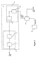
- the communications system 1 comprises a set of base stations B1 ... Bn, each base station Bi being capable of communicating with a set of outstations Ol Bi ... On Bi (where i and n are index identifiers indicating that any given base station B i has n outstations associated therewith).
- Each of the base stations and outstations is capable of duplex communications and the base stations transmit data according to a frame structure.
- the transmission includes elements that are relevant to all outstations, and elements that are specifically for one outstation.
- Time Division Duplex is used to multiplex the messages onto a single carrier, and the modulation employed is 500 bits per second (bps) continuous-phase Frequency Shift Keyed (FSK) with ⁇ 250 Hz deviation.
- the base stations use frequency hopping as mandated by the Federal Bureau of Communications (FCC), which involves changing the transmit frequency every 0.4 seconds.
- FCC Federal Bureau of Communications
- the format of a given frame will be described in detail below, but suffice to say that the corollary of this frequency hopping condition is that any given time slot within a frame has a duration of 0.4 seconds; thus for a downlink bit transmission rate of 500 bps any given time slot can contain up to 200 bits of data.
- the outstation comprises a receiver 10, a transmitter 13 and is in operative association with a meter collector 14, which is typically a conventional meter reading device such as is installed in domestic premises.
- the receiver 10 is arranged to decode frame data received from the base station, as is described in detail below, and the collector 14 is arranged to collect meter data and forward the same to the transmitter 13 for transmission at a time determined by the frame format, as will be described in detail below.
- the downlink transmission rate is 500 bps; the uplink transmission rate is significantly slower than the downlink rate - preferably 8 times slower, i.e. 62.5 Hz - so that the uplink round trip delay for an outstation located 10 km from the base station is very small in relation to the uplink bit period (67 ⁇ s vs 16ms).
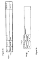
- transmissions from a base station are typically organised in frames, which, as shown in Figure 2a , include a plurality of time slots, each of which is dedicated to a transmitting/receiving event (on the part of the base station or outstation).
- a preamble always appears at the beginning of the transmission and occupies the start of every frame (time slot 1); thus detection of a preamble in a base station's transmission is the first stage in demodulation by the receiver 10 of the transmissions from the base station.
- the preamble comprises two sequences of data P1, P2, the second sequence P2 being the inverse of at least part of the first sequence P1.
- the remainder of the time slot 1 comprises payload and error detection portions (not shown).
- the first and second sequences P1, P2 are preferably periodic; for example the first sequence can comprise a so-called dotting sequence ⁇ 0, 1, 0, 1 ... ⁇ and the second sequence can comprise a so-called anti-dotting sequence ⁇ 1, 0, 1, 0 ... ⁇ .
- the sequences contain a pattern that repeats within the sequence, and comprises a non-prime number of elements (the dotting/anti-dotting sequence comprises a repeating pattern of two elements (0, 1) and (1, 0) respectively).
- the pattern comprises an arbitrary sequence of bits and the second sequence can comprise a different number of repetitions to that included in the first sequence.
- the first sequence P1 comprises 24 pairs of dotting and the second sequence P2 comprises 8 pairs of anti-dotting.
- the receiver 10 comprises an analogue receiver part 3 and a signal processor 5, and in one embodiment the analogue receiver part 3 comprises a down converter 7, which converts the carrier frequency of the received data signal to an intermediate frequency (IF) of approximately 8 kHz.
- IF intermediate frequency
- the quadrature IF signals are sampled by an Analogue to Digital Converter 9 (ADC), which generates, as output, complex 2x12-bit samples at 32 ksps having an effective noise bandwidth of 20 kHz; the output of the ADC 9 is fed into the signal processor 5.
- ADC Analogue to Digital Converter
- embodiments of the invention transmit and receive at low data rates so as to keep power requirements to a minimum yet be able to transceive data over long distances.
- the outstation has identified the nominal carrier frequency associated with the time slot, though not the actual value of the carrier frequency as it appears to the oscillator local to the outstation; there is therefore an as yet undetermined frequency error between the base station and the outstation (that is to say the difference between the value of the frequency at which signals are transmitted and the value that such frequencies appear to be to the outstation).
- this frequency error can be greater than the signal bandwidth, since this is, by definition, small.
- the demodulating part 11 In order to be able to successfully demodulate the signal in a narrow noise bandwidth (which is essential for long range) it is necessary to remove the frequency error. In embodiments of the invention this is done by means of a Fast Fourier Transform (FFT) which, with reference to Figure 3 , is implemented within a demodulating part 11 of the signal processor 5 and essentially acts as a bank of filters spaced based around the outstation's version of the carrier frequency. As shown in Figure 4 , in addition to an FFT 19, the demodulating part 11 also comprises a narrowband detector element 21, which serves to identify bit timing associated with the preamble, as will be described in more detail below.
- FFT Fast Fourier Transform
- a transmitting part 13 uses the bit timing information to calibrate the timing of the outstation, essentially synchronising the time slots, as they appear to the clock of the outstation, with those of the base station. This in turn enables the outstation to synchronise transmission of the uplink data with the expected time of receipt of uplink data at the base station, and, because the uplink data rate is low, this relieves the base station from having to identify where the uplink data are in the time domain.
- the demodulating part 11 comprises an oscillator 15 for mixing the received samples to base-band, and means 17 for decimating the mixed signal so as to modify the rate at which data are introduced to the FFT 19; the oscillator 15 multiplies the ADC samples received from the analogue receiver part 3 by a complex exponential tuned to the nominal IF (8 kHz) and the decimation applied by part 17 results in a baseband signal nominally centred at 0 Hz and sampled at 4 kHz.
- the oscillator 15 is preferably in operative association with an anti-aliasing filter (not shown) acting as a low-pass filter.
- samples are introduced into the FFT at a rate of 4 kHz; in a preferred arrangement the bin resolution of the FFT is chosen to be 62.5 Hz, meaning that the FFT 19 comprises a 64 point FFT (4000/62.5), as indicated in Figure 5 .
- the FFT 19 is preferably carried out every 1 ms, so that for an input rate of 4 kHz, 4 new samples are added for each iteration of the FFT and the FFT bins span ⁇ 2 kHz, which means that for a data rate of 500 bps (i.e. a bit period of 2 ms) there will be 2 FFT results in every bit period.
- the input samples are indicated as being complex samples; for such arrangements bins 32 to 63 correspond to negative frequencies, which means that the ordering of the bins has to be re-ordered in accordance with ascending order of frequency prior to evaluating the difference between respective pairs of separated bins.
- the output of the FFT 19 is a set of 56 demodulated frequency offsets, and typically a subset of the set (e.g. the central 52 or 50 or 47; preferably 47, indicated by I 0...47 ) is selected for input to the narrowband detector 21.
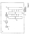
- the narrowband detector 21 comprises a plurality of detector elements 21 0 ... 21 47 (only one, 21 a, is shown in Figure 6 ), each of which receives one of the (47) demodulated inputs I a from the FFT 19, and mixes the input with an oscillator 25a in order to mix the fundamental of the periodic pattern down to 0 Hz.
- the output of the oscillator 25a is then low-pass filtered by means of a leaky integrator 27a (e.g. an impulse response filter), which essentially sums the magnitude of successively received inputs from the FFT 19.
- a leaky integrator (as opposed to other filter types) is preferable for the low-pass filter because it provides a convenient mechanism for adjusting the bandwidth without affecting processing or memory requirements.
- Figure 7 shows the frequency response 29 of the leaky integrator 27a and the time response of the detector to successively received parts of an ideal preamble signal.
- the relatively sharp decay 31 of the response 29 results from the anti-dotting sequence P2 of the preamble portion, and, because the transition from the dotting sequence P1 to the anti-dotting sequence P2 occurs within a single bit, it is this part of the response that enables bit timing to be identified from the preamble.
- each narrowband detector element 21 a also comprises means 33a, 35a for calculating the mean magnitude and phase of the input I a received from the FFT 19, and the magnitude values are input to an algorithm 41 for determining whether or not the input I a received from the FFT 19 corresponds to a preamble (rather than noise).
- Various mechanisms can be utilised to implement the trigger criteria, and in fact the roll-off associated with various other parts of the receiver 10 means that there is no single value that is appropriate for all of the inputs received from the FFT 19; instead the trigger threshold that is appropriate for a given input I a from the FFT 19 is selected and input to the algorithm 41, modified (where appropriate) to account for local interference, as indicated as part 37a in Figure 6 .
- the algorithm 41 compares the mean magnitude received from each narrowband detector 21 0...47 against its respective threshold value, and in the event that the magnitude for that output exceeds the threshold value for more than a specified period of time, the receiver 10 enters into a "triggered" state in respect of the narrowband detector element 21 i under examination. Having reviewed the set of magnitude outputs from all of the narrowband detector elements 21 0...47 , the algorithm 41 identifies the output having the largest magnitude, and this is used to define a new threshold, Th detect . This new threshold is applied to the output of all of the narrowband detector elements 21 0...47 and the process repeated until the signal level in a "triggered" narrowband detector element 21 i drops below the threshold: this point is deemed indicative of transition point 31 shown in Figure 7 .
- timeout-related conditions can also be applied in order to eliminate false detections, and the skilled person would be able to design appropriate controls to mitigate these.
- the output of the demodulating part 11, which comprises successively generated magnitude information identified by the algorithm 41, is input to a controller 15.
- the controller 15 can be used to identify both the frequency error and the bit timing on the basis of the outputs from the narrowband detector elements 21 0...47 and the algorithm 41 (as described above and based on Figure 7 ); once these have been determined, the controller 15 adjusts the internal clock of the outstation on the basis of the bit timing information, in accordance with known methods. According to various tests that have been performed, timing synchronisation at the outstation in relation to downlink transmissions can be achieved in this manner to something like within 1/4 bit.
- the transmitting part 3 FSK modulates a predetermined carrier frequency, firstly using a predetermined identifier, and then using any meter data received from the collector 14. Since the outstation timing has been adjusted so as to concord with that of the timing of the base station, and because the uplink data rate is 1/8 of the downlink data rate, the afore-mentioned 1 ⁇ 4 bit timing accuracy on the downlink maps to 1/32 of a bit on the uplink; for practical purposes, this can be considered to be perfect.
- the predetermined identifier preceding the meter data essentially signals the presence of meter data to the base station and is included simply to assist the base station in detecting the presence of transmissions from outstations and to measure signal strengths; importantly, the transmitting part 13 is not required to precede the uplink payload with a bespoke synch word, such as is normally sent when the base station is required to identify where the uplink data are in the time domain.
- first and second sequences P1, P2 could be embodied as a dotting sequence based on the 1100 pattern, which would make the FFT 19 more resistant to noise, but at the cost of requiring longer sequences.
- embodiments of the invention are concerned with a system for use in narrowband RF system, in which data are transceived between radio stations in frames comprising slots having finite periods (and thus discrete start and end points within the frame), and the timing of a clock internal to a given station determines where in time respective slots start and finish.
- the synchronisation between two communicating radio stations is configured on the basis of timing information derived from a preamble portion of a given frame that is transmitted from a first station to a second.
- This timing information is used to configure a clock internal to the second station; by adjusting the time of the clock, the timing of the slots within a given frame can therefore be controlled.
- This can be particularly advantageously applied to the uplink slots of the given frame (i.e. when the second base station transmits its data to the first station) so as to ensure that data received on the uplink are synchronised with timing characteristics of the first (data processing) station.
- the data transmitted from the first station is transmitted at a first data rate
- the data transmitted from the second station is transmitted at a second data rate
- the second data rate is lower than the first data rate.
- a separate synchronisation word is not required to be sent from the second station to the first station on the uplink portion; instead, and because the uplink slots of a given frame are synchronised between transceiving stations, the start of the uplink payload slot can comprise signalling information which simply acts to signify the start of transmission of uplink data from the second station.
Landscapes
- Engineering & Computer Science (AREA)
- Computer Networks & Wireless Communication (AREA)
- Signal Processing (AREA)
- Mobile Radio Communication Systems (AREA)
- Time-Division Multiplex Systems (AREA)
- Synchronisation In Digital Transmission Systems (AREA)
Description
- The present invention relates to a system for and method of digital communications, and is particularly, but not exclusively, suited to transceiving data at low data rates.
- The majority of point-to-multipoint radio communications systems operate at relatively high bandwidths, due to the high data rates and real-time requirements associated with data receipt and transmission. It would be attractive to operate at low bandwidths for applications having less stringent data rate requirements because of the commensurate advantages in relation to range and reduction in power requirements. However, low bandwidth systems can incur significant frequency lock problems due to the fact that the frequency error between the transmitter and the receiver is much greater than the signal bandwidth; the identification of the frequency error typically involves use of high accuracy components, which equates to a significant overhead in terms of costs, and to a commensurate limitation in the use of low bandwidth systems.
- US patent
US 6,522,698 offers a low cost solution in which the bulk of the decoding and processing is performed in the central station, any given remote station simply having to transmit at a relatively low data rate: the remote station (or outstation) is configured so as to generate uplink messages arbitrarily in time, leaving it to the base station to identify the unique signature of any given remote station. Typically, this involves providing the base station with many sliding detectors, which are expensive in terms of computational requirements, and, for a large number of remote stations, can become prohibitively costly. -
EP 1643268 discloses a system in which there is two-way communication between an RFID tag and an interrogator over short distances (within a building or campus). -
WO2004/032380 discloses a frame structure, for radio communication, which comprises a sequence of uplink slots, and sequence of downlink slots, the duration of the downlink slots being greater than the duration of the uplink slots and the downlink data rate being greater than uplink data rate. -
EP0131662 discloses a system for synchronising data transmissions in a distributed communication network comprising remote stations and a central station. The timings of transmissions from remote stations to the central station are offset in accordance with a calculated transmission delay. - It would be desirable to provide a lower cost narrow band transmission system that is suitable for use with a significant number of remote outstations.
- In accordance with one aspect of the present invention, there is provided a method of signalling the transmission of data from a first transceiver to a second transceiver, the data being contained within a set of time slots, wherein the time of flight of said data between the first and second transceivers is several orders of magnitude lower than the bit period for transmission of said data from the first transceiver to the second transceiver, the first and second transceivers each being capable of transmitting data over a range of ten kilometres, the method comprising:
- receiving data transmitted from the second transceiver at the first transceiver;
- adjusting timing associated with the first transceiver on the basis of the data received from the second transceiver so as to synchronise a bit timing characteristic of the first transceiver with a bit timing characteristic of the second transceiver;
- transmitting signalling information identifying transmission of payload data from the first transceiver, the signalling information being transmitted on the basis of the bit timing characteristic determined from the adjusted timing of the first transceiver,
- transmitting said payload data from the first transceiver using the synchronised bit timing of the first transceiver; and
- receiving said payload data at the second transceiver using the synchronised bit timing of the second transceiver,
- wherein the data transmitted from the first transceiver is transmitted at a first data rate, the data transmitted from the second transceiver is transmitted at a second data rate, and the first data rate is less than one half of the second data rate.
- In at least one embodiment of the invention the second transceiver is embodied as a central station (commonly referred to as a base station) and the first transceiver by an outstation remote therefrom; thus in embodiments of the invention, the remote station is arranged to adjust timing information on the basis of data received from the base station, and uses the timing data to synchronise itself with the base station.
- The first data rate can be less than one half, one third, one fifth, or approximately one tenth of the second data rate. Most preferably the first data rate is one eighth of the second data rate, so for a second, or downlink, transmission rate of 500 bits per second (bps), the uplink transmission rate is preferably 8 times slower, i.e. 62.5 Hz. As a result, the uplink round trip delay for an outstation located 10 km from the base station is very small in relation to the uplink bit period (67µs vs 16ms).
- Whilst 62.5 bps is a preferred data rate for the uplink, other uplink data rates are possible, preferably ranging between 16 and 1500 bps: for an uplink data rate of 16 bits per second the downlink data rate is preferably greater than 32 bps and is most preferably 128 bps; for an uplink data rate of 500 bps the downlink data rate is preferably greater than 1000 bps and is most preferably 4000 bps, whilst for an uplink data rate of 1500 bps the downlink data rate is preferably greater than 3000 bps and most preferably 12000 bps.
- When the timing of the remote outstation is adjusted on the basis of data received from the base station according to embodiments of the invention, approximately ¼ bit timing accuracy can be achieved on the downlink. For the case in which the uplink data rate is 1/8 of the downlink data rate, ¼ bit timing accuracy on the downlink maps to 1/32 of a bit on the uplink, and for practical purposes, this can be considered to be perfect. In view of the additional fact that the time of flight for data transmitted over a range of approximately 10 km is several orders of magnitude lower than the uplink bit period (16 ms), this all leads to a situation in which uplink time slots can be considered to be perfectly synchronised between base station and outstation and thus relieves the base station from having to identify uplink transmissions from individual outstations in the time domain.
- Thus this synchronisation can be used most effectively when transmitting data to the base station, since if the remote station is synchronised with the base station, this implicitly reduces the amount of processing that is required to be performed by the base station upon receipt of signals from remote stations. It will be appreciated that when there is a significant number of such remote stations, each transmitting somewhat independently of one another, this significantly relieves the processing requirements on the base station that would otherwise be required with prior art systems such as
US 6,522,698 . - Further features and advantages of the invention will become apparent from the following description of preferred embodiments of the invention, given by way of example only, which is made with reference to the accompanying drawings.
-
-
Figure 1 is a schematic diagram showing an example of a point-multipoint system within which embodiments of the invention can operate; -
Figure 2a is a schematic diagram showing allocation of time slots of a frame according to embodiments of the invention; -
Figure 2b is a schematic diagram showing portions of a first time slot of the frame shown inFigure 2a ; -
Figure 3 is a schematic diagram showing components of a receiver utilised by an outstation shown inFigure 1 ; -
Figure 4 is a schematic block diagram showing components of the signal processor ofFigure 3 ; -
Figure 5 is a schematic block diagram showing components of an FFT-based parallel demodulator forming part of the receiver ofFigure 4 ; -
Figure 6 is a schematic block diagram showing components of a narrowband detector ofFigure 4 ; and -
Figure 7 is a graphical representation of output of a leaky integrator component shown inFigure 6 . - The transceivers and communications systems described herein have general application. However, for clarity, the systems and methods are described in the context of remote metering systems such as are used in conjunction with utility meters in a domestic or commercial environment. It is to be understood, however, that the invention is not limited to such applications. For example, the present invention may be applied to low data rate telemetry from remote (e.g. non-mains powered) installations such as water reservoirs; from personal or property accident or attack security alarms such as rape alarms, mountain rescue alarms, etc.; security systems for buildings, low-power wireless alarms, connection of static alarms to a national central monitoring system; remote controls for example in a domestic environment such as for electrical appliance control; remote controls for use in controlling devices such as street lamps; tracking systems for recovering stolen property such as vehicles; and non-radio communications system using, for example, signalling via electricity mains supply. The following description makes mention of various values - in terms of frequency, sampling rates etc.; it is to be appreciated that the particular values are exemplary only and that the invention is not to be limited to any particular individual or combinations of values.
- Referring to
Figure 1 , in one arrangement, thecommunications system 1 comprises a set of base stations B1 ... Bn, each base station Bi being capable of communicating with a set of outstations OlBi ... OnBi (where i and n are index identifiers indicating that any given base station Bi has n outstations associated therewith). Each of the base stations and outstations is capable of duplex communications and the base stations transmit data according to a frame structure. The transmission includes elements that are relevant to all outstations, and elements that are specifically for one outstation. Time Division Duplex (TDD) is used to multiplex the messages onto a single carrier, and the modulation employed is 500 bits per second (bps) continuous-phase Frequency Shift Keyed (FSK) with ±250 Hz deviation. Whilst not essential, in some arrangements (e.g. when thecommunications system 1 is used in the USA) the base stations use frequency hopping as mandated by the Federal Bureau of Communications (FCC), which involves changing the transmit frequency every 0.4 seconds. The format of a given frame will be described in detail below, but suffice to say that the corollary of this frequency hopping condition is that any given time slot within a frame has a duration of 0.4 seconds; thus for a downlink bit transmission rate of 500 bps any given time slot can contain up to 200 bits of data. - A first aspect of the invention is concerned with the functionality of the outstations, specifically the transmitter and receiver parts thereof, and will be described in the context of a frame according to an embodiment of the invention. Turning to
Figure 3 , in overview, the outstation comprises areceiver 10, atransmitter 13 and is in operative association with ameter collector 14, which is typically a conventional meter reading device such as is installed in domestic premises. Thereceiver 10 is arranged to decode frame data received from the base station, as is described in detail below, and thecollector 14 is arranged to collect meter data and forward the same to thetransmitter 13 for transmission at a time determined by the frame format, as will be described in detail below. - As mentioned above, the downlink transmission rate is 500 bps; the uplink transmission rate is significantly slower than the downlink rate - preferably 8 times slower, i.e. 62.5 Hz - so that the uplink round trip delay for an outstation located 10 km from the base station is very small in relation to the uplink bit period (67µs vs 16ms).
- As is well known in the art, transmissions from a base station are typically organised in frames, which, as shown in
Figure 2a , include a plurality of time slots, each of which is dedicated to a transmitting/receiving event (on the part of the base station or outstation). A preamble always appears at the beginning of the transmission and occupies the start of every frame (time slot 1); thus detection of a preamble in a base station's transmission is the first stage in demodulation by thereceiver 10 of the transmissions from the base station. Referring toFigure 2b , in one arrangement the preamble comprises two sequences of data P1, P2, the second sequence P2 being the inverse of at least part of the first sequence P1. The remainder of thetime slot 1 comprises payload and error detection portions (not shown). - The first and second sequences P1, P2 are preferably periodic; for example the first sequence can comprise a so-called dotting sequence {0, 1, 0, 1 ...} and the second sequence can comprise a so-called anti-dotting sequence {1, 0, 1, 0 ...}. In general the sequences contain a pattern that repeats within the sequence, and comprises a non-prime number of elements (the dotting/anti-dotting sequence comprises a repeating pattern of two elements (0, 1) and (1, 0) respectively). Preferably the pattern comprises an arbitrary sequence of bits and the second sequence can comprise a different number of repetitions to that included in the first sequence. In a most preferred arrangement the first sequence P1 comprises 24 pairs of dotting and the second sequence P2 comprises 8 pairs of anti-dotting.
- The significance of the preamble in relation to aspects of the transmitter and receiver will now be described with reference to
Figures 3 - 5 . Thereceiver 10 comprises ananalogue receiver part 3 and asignal processor 5, and in one embodiment theanalogue receiver part 3 comprises adown converter 7, which converts the carrier frequency of the received data signal to an intermediate frequency (IF) of approximately 8 kHz. The quadrature IF signals are sampled by an Analogue to Digital Converter 9 (ADC), which generates, as output, complex 2x12-bit samples at 32 ksps having an effective noise bandwidth of 20 kHz; the output of theADC 9 is fed into thesignal processor 5. - As described above, embodiments of the invention transmit and receive at low data rates so as to keep power requirements to a minimum yet be able to transceive data over long distances. In the following, it is assumed that the outstation has identified the nominal carrier frequency associated with the time slot, though not the actual value of the carrier frequency as it appears to the oscillator local to the outstation; there is therefore an as yet undetermined frequency error between the base station and the outstation (that is to say the difference between the value of the frequency at which signals are transmitted and the value that such frequencies appear to be to the outstation). As described in the background section this frequency error can be greater than the signal bandwidth, since this is, by definition, small.
- In order to be able to successfully demodulate the signal in a narrow noise bandwidth (which is essential for long range) it is necessary to remove the frequency error. In embodiments of the invention this is done by means of a Fast Fourier Transform (FFT) which, with reference to
Figure 3 , is implemented within ademodulating part 11 of thesignal processor 5 and essentially acts as a bank of filters spaced based around the outstation's version of the carrier frequency. As shown inFigure 4 , in addition to anFFT 19, thedemodulating part 11 also comprises anarrowband detector element 21, which serves to identify bit timing associated with the preamble, as will be described in more detail below. - Returning to
Figures 2b and3 , once the bit timing has been identified, this is passed to a transmittingpart 13, which uses the bit timing information to calibrate the timing of the outstation, essentially synchronising the time slots, as they appear to the clock of the outstation, with those of the base station. This in turn enables the outstation to synchronise transmission of the uplink data with the expected time of receipt of uplink data at the base station, and, because the uplink data rate is low, this relieves the base station from having to identify where the uplink data are in the time domain. - The details of these various parts and processes will now be described in detail, starting with the
demodulating part 11 and referring firstly toFigure 4 . It is to be understood that the mechanism described herein for retrieving the bit timing from received downlink data is not essential to embodiments of the invention: more specifically, embodying the preamble portion as a first and second sequence P1, P2 as described above and utilised in the manner described below provides for an extremely efficient and low cost method of identifying bit timing (so is indeed a preferred method). However, any type of preamble and alternative decoding method could be used, provided it facilitates extraction of synchronisation between the clocks of the base station and outstation respectively. - In one arrangement the
demodulating part 11 comprises anoscillator 15 for mixing the received samples to base-band, and means 17 for decimating the mixed signal so as to modify the rate at which data are introduced to theFFT 19; theoscillator 15 multiplies the ADC samples received from theanalogue receiver part 3 by a complex exponential tuned to the nominal IF (8 kHz) and the decimation applied bypart 17 results in a baseband signal nominally centred at 0 Hz and sampled at 4 kHz. Theoscillator 15 is preferably in operative association with an anti-aliasing filter (not shown) acting as a low-pass filter. As a result of the decimation, therefore, samples are introduced into the FFT at a rate of 4 kHz; in a preferred arrangement the bin resolution of the FFT is chosen to be 62.5 Hz, meaning that theFFT 19 comprises a 64 point FFT (4000/62.5), as indicated inFigure 5 . - The
FFT 19 is preferably carried out every 1 ms, so that for an input rate of 4 kHz, 4 new samples are added for each iteration of the FFT and the FFT bins span ± 2 kHz, which means that for a data rate of 500 bps (i.e. a bit period of 2 ms) there will be 2 FFT results in every bit period. Demodulation of the preamble is effected by taking the difference in magnitude between pairs of bins separated by twice
portion 23 inFigure 5 . This is quite different to methods such as that described in US patentUS6,522,698 , in which demodulation is performed as a separate process to that of frequency identification (in addition to being performed at the base station as opposed to in the outstations). - In
Figure 5 the input samples are indicated as being complex samples; forsuch arrangements bins 32 to 63 correspond to negative frequencies, which means that the ordering of the bins has to be re-ordered in accordance with ascending order of frequency prior to evaluating the difference between respective pairs of separated bins. The output of theFFT 19 is a set of 56 demodulated frequency offsets, and typically a subset of the set (e.g. the central 52 or 50 or 47; preferably 47, indicated by I0...47) is selected for input to thenarrowband detector 21. - The
narrowband detector 21 comprises a plurality ofdetector elements 210 ... 2147 (only one, 21 a, is shown inFigure 6 ), each of which receives one of the (47) demodulated inputs Ia from theFFT 19, and mixes the input with anoscillator 25a in order to mix the fundamental of the periodic pattern down to 0 Hz. The output of theoscillator 25a is then low-pass filtered by means of aleaky integrator 27a (e.g. an impulse response filter), which essentially sums the magnitude of successively received inputs from theFFT 19. A leaky integrator (as opposed to other filter types) is preferable for the low-pass filter because it provides a convenient mechanism for adjusting the bandwidth without affecting processing or memory requirements. -
Figure 7 shows thefrequency response 29 of theleaky integrator 27a and the time response of the detector to successively received parts of an ideal preamble signal. The relativelysharp decay 31 of theresponse 29 results from the anti-dotting sequence P2 of the preamble portion, and, because the transition from the dotting sequence P1 to the anti-dotting sequence P2 occurs within a single bit, it is this part of the response that enables bit timing to be identified from the preamble. - Turning back to
Figure 6 , eachnarrowband detector element 21a also comprisesmeans FFT 19, and the magnitude values are input to analgorithm 41 for determining whether or not the input Ia received from theFFT 19 corresponds to a preamble (rather than noise). Various mechanisms can be utilised to implement the trigger criteria, and in fact the roll-off associated with various other parts of thereceiver 10 means that there is no single value that is appropriate for all of the inputs received from theFFT 19; instead the trigger threshold that is appropriate for a given input Ia from theFFT 19 is selected and input to thealgorithm 41, modified (where appropriate) to account for local interference, as indicated aspart 37a inFigure 6 . - In one arrangement, the
algorithm 41 compares the mean magnitude received from eachnarrowband detector 210...47 against its respective threshold value, and in the event that the magnitude for that output exceeds the threshold value for more than a specified period of time, thereceiver 10 enters into a "triggered" state in respect of thenarrowband detector element 21i under examination. Having reviewed the set of magnitude outputs from all of thenarrowband detector elements 210...47, thealgorithm 41 identifies the output having the largest magnitude, and this is used to define a new threshold, Thdetect. This new threshold is applied to the output of all of thenarrowband detector elements 210...47 and the process repeated until the signal level in a "triggered"narrowband detector element 21i drops below the threshold: this point is deemed indicative oftransition point 31 shown inFigure 7 . - Various timeout-related conditions can also be applied in order to eliminate false detections, and the skilled person would be able to design appropriate controls to mitigate these.
- Returning back to
Figure 3 , the output of thedemodulating part 11, which comprises successively generated magnitude information identified by thealgorithm 41, is input to acontroller 15. Thecontroller 15 can be used to identify both the frequency error and the bit timing on the basis of the outputs from thenarrowband detector elements 210...47 and the algorithm 41 (as described above and based onFigure 7 ); once these have been determined, thecontroller 15 adjusts the internal clock of the outstation on the basis of the bit timing information, in accordance with known methods. According to various tests that have been performed, timing synchronisation at the outstation in relation to downlink transmissions can be achieved in this manner to something like within 1/4 bit. - Referring back to
Figure 2a , at a time corresponding totime slot 3, the transmittingpart 3 FSK modulates a predetermined carrier frequency, firstly using a predetermined identifier, and then using any meter data received from thecollector 14. Since the outstation timing has been adjusted so as to concord with that of the timing of the base station, and because the uplink data rate is 1/8 of the downlink data rate, the afore-mentioned ¼ bit timing accuracy on the downlink maps to 1/32 of a bit on the uplink; for practical purposes, this can be considered to be perfect. In view of the additional fact that the time of flight for data transmitted over a range of approximately 10 km is several orders of magnitude lower than the uplink bit period (16 ms), this all leads to a situation in which uplink time slots can be considered to be perfectly synchronised between base station and outstation and thus relieves the base station from having to identify uplink transmissions from individual outstations in the time domain. - It will therefore be appreciated that the predetermined identifier preceding the meter data essentially signals the presence of meter data to the base station and is included simply to assist the base station in detecting the presence of transmissions from outstations and to measure signal strengths; importantly, the transmitting
part 13 is not required to precede the uplink payload with a bespoke synch word, such as is normally sent when the base station is required to identify where the uplink data are in the time domain. - The above embodiments are to be understood as illustrative examples of the invention. Further embodiments of the invention are envisaged. For example, the first and second sequences P1, P2 could be embodied as a dotting sequence based on the 1100 pattern, which would make the
FFT 19 more resistant to noise, but at the cost of requiring longer sequences. - It will thus be appreciated that embodiments of the invention are concerned with a system for use in narrowband RF system, in which data are transceived between radio stations in frames comprising slots having finite periods (and thus discrete start and end points within the frame), and the timing of a clock internal to a given station determines where in time respective slots start and finish. In one arrangement the synchronisation between two communicating radio stations (first and second stations) is configured on the basis of timing information derived from a preamble portion of a given frame that is transmitted from a first station to a second. This timing information is used to configure a clock internal to the second station; by adjusting the time of the clock, the timing of the slots within a given frame can therefore be controlled. This can be particularly advantageously applied to the uplink slots of the given frame (i.e. when the second base station transmits its data to the first station) so as to ensure that data received on the uplink are synchronised with timing characteristics of the first (data processing) station.
- In embodiments of the invention the data transmitted from the first station is transmitted at a first data rate, the data transmitted from the second station is transmitted at a second data rate, and the second data rate is lower than the first data rate. In view of the difference in data rates and the synchronisation between radio stations, a separate synchronisation word is not required to be sent from the second station to the first station on the uplink portion; instead, and because the uplink slots of a given frame are synchronised between transceiving stations, the start of the uplink payload slot can comprise signalling information which simply acts to signify the start of transmission of uplink data from the second station.
- It is to be understood that any feature described in relation to any one embodiment may be used alone, or in combination with other features described, and may also be used in combination with one or more features of any other of the embodiments, or any combination of any other of the embodiments. Furthermore, equivalents and modifications not described above may also be employed without departing from the scope of the invention, which is defined in the accompanying claims.
Claims (18)
- A method of signalling the transmission of data from a first transceiver to a second transceiver, the data being contained within a set of time slots, wherein the time of flight of said data between the first and second transceivers is several orders of magnitude lower than the bit period for transmission of said data from the first transceiver to the second transceiver, the first and second transceivers each being capable of transmitting data over a range of ten kilometres, the method comprising:receiving data transmitted from the second transceiver at the first transceiver;adjusting timing associated with the first transceiver on the basis of the data received from the second transceiver so as to synchronise a bit timing characteristic of the first transceiver with a bit timing characteristic of the second transceiver;transmitting signalling information identifying transmission of payload data from the first transceiver, the signalling information being transmitted on the basis of the bit timing characteristic determined from the adjusted timing of the first transceiver;transmitting said payload data from the first transceiver using the synchronised bit timing of the first transceiver; andreceiving said payload data at the second transceiver using the synchronised bit timing of the second transceiver,wherein the data transmitted from the first transceiver is transmitted at a first data rate, the data transmitted from the second transceiver is transmitted at a second data rate, and the first data rate is less than one half of the second data rate.
- A method according to claim 1, in which the first data rate is less than one third of the second data rate.
- A method according to claim 1, in which the first data rate is less than one fifth of the second data rate.
- A method according to claim 1, in which the first data rate is less than one eighth of the second data rate.
- A method according to claim 1, in which the first data rate is less than approximately one tenth of the second data rate.
- A method according to any one of the preceding claims, in which the first data rate is 1500 bits per second.
- A method according to any one of the preceding claims, in which the first data rate is 500 bits per second.
- A method according to any one of the preceding claims, in which the first data rate is 62.5 bits per second.
- A method according to any one of the preceding claims, in which the first data rate is 16 bits per second.
- A method according to any one of the preceding claims, in which the second transceiver comprises a base station operable to communicate with a plurality of first transceivers.
- A method according to any one of the preceding claims, in which the first transceiver comprises a remote station operable to communicate with a base station.
- A method according to claim 11, in which the first transceiver is operable to communicate with at least one other remote station.
- A method according to any one of the preceding claims, in which said data is transmitted from the second transceiver as a signal comprising a set of time slots, at least one said slot comprising a preamble portion and being transmitted at a predetermined transmission frequency, said predetermined frequency lying within a known range of frequencies and the preamble portion comprising at least a first sequence of data (P1) and a second sequence of data (P2), the second sequence (P2) being the inverse of the first sequence (P1),
the method further comprising:dividing the range of frequencies into a plurality of frequency bands, andfor each data item contained within the preamble portion:identifying a magnitude of signal received within each said frequency band;subtracting a first signal magnitude identified for a first said frequency band from a second signal magnitude identified for a second said frequency band, whereby to demodulate the signal within at least part of said preamble portion, andcombining the subtracted signal magnitudes with output from an oscillator (25a) tuned to a fundamental of a period associated with said first sequence (P1),andaccumulating the combined signal magnitudes over the preamble portion, whereby to derive said timing data from the first (P1) and the second (P2) sequences of data for use in performing said timing adjustment of the first transceiver. - A method according to claim 13, including
monitoring changes in said accumulated combined magnitudes for successive data items within the preamble portion so as to identify an interface (31) between said first (P1) and said second (P2) sequences of data; and
identifying a phase associated with said interface (31) so as to determine said timing data. - A system for transmitting data within a set of time slots, the system comprising a first transceiver and a second transceiver, wherein the time of flight between the first and second transceivers is several orders of magnitude lower than the bit period for transmission of said data from the first transceiver to the second transceiver, the first and second transceivers each being capable of transmitting data over a range of ten kilometres, the first transceiver being arranged to:receive data transmitted from the second transceiver;adjust timing associated with the first transceiver on the basis of the data received from the second transceiver so as to synchronise a bit timing characteristic of the first transceiver with a bit timing characteristic of the second transceiver;transmit signalling information identifying transmission of payload data from the first transceiver, the signalling information being transmitted on the basis of the bit timing characteristic determined from the adjusted timing of the first transceiver; andtransmit said payload data from the first transceiver using the synchronised bit timing of the first transceiver,
the second transceiver being arranged to;receive said payload data using the synchronised bit timing of the second transceiver,wherein the data transmitted from the first transceiver is transmitted at a first data rate, the data transmitted from the second transceiver is transmitted at a second data rate, and the first data rate is less than one half of the second data rate. - A system according to claim 15, wherein the first transceiver is a narrowband transceiver comprising:an antenna for transceiving a signal between said first transceiver and said second transceiver, the signal comprising a set of time slots, at least one said slot comprising a preamble portion and a payload portion and being transmitted at a predetermined transmission frequency, wherein said predetermined frequency is within a known range of frequencies;a clock for controlling allocation of uplink portions within a given slot according to a timing characteristic thereof;a digital filter arranged to divide the range of frequencies of a signal received from the first transceiver into a plurality of frequency bands, wherein, for each data item contained within the preamble portion of a given time slot, the filter is arranged to identify a magnitude of signal received within each said frequency band and identify a plurality of pairs of frequency bands, each said pair of frequency bands comprising a first frequency band and a second frequency band, the filter being arranged, for at least some of the plurality of pairs of frequency bands, to subtract a first signal magnitude identified for said first said frequency band from a second signal magnitude identified for said second said frequency band, whereby to demodulate the signal within at least part of said preamble portion of the given time slot;a detector element (21) arranged to combine the subtracted signal magnitudes corresponding to respective pairs of frequency bands with output from an oscillator (25a) tuned to a fundamental of a period associated with said preamble portion, wherein, for each pair of first and second said frequency bands, the detector element (21) is arranged to accumulate the combined signal magnitudes over the preamble portion, so as to identify timing information for the given time slot;means for adjusting the timing characteristic of the clock on the basis of the identified timing information of the given time slot; andmeans for allocating signalling information to an uplink payload portion within the given slot, the means being arranged to determine the uplink payload portion using adjusted timing characteristic of the clock and thence allocate the signalling information to the adjusted uplink payload portion,wherein the data transmitted from the first transceiver is transmitted at a first data rate, the data transmitted from the second transceiver is transmitted at a second data rate, and the first data rate is less than one half of the second data rate.
- A computer program or set of computer programs which, when executed, causes first and second transceivers to perform a method according to any of claim 1 to claim 14.
- A computer program or set of computer programs which, when executed, causes a system to function according to the system of either claim 15 or claim 16.
Applications Claiming Priority (2)
| Application Number | Priority Date | Filing Date | Title |
|---|---|---|---|
| GB0624017A GB2444308B (en) | 2006-12-01 | 2006-12-01 | Narrow band transceiver |
| PCT/GB2007/004596 WO2008065414A2 (en) | 2006-12-01 | 2007-11-30 | Narrow band transceiver |
Publications (2)
| Publication Number | Publication Date |
|---|---|
| EP2092682A2 EP2092682A2 (en) | 2009-08-26 |
| EP2092682B1 true EP2092682B1 (en) | 2013-01-09 |
Family
ID=37671678
Family Applications (1)
| Application Number | Title | Priority Date | Filing Date |
|---|---|---|---|
| EP07848418A Active EP2092682B1 (en) | 2006-12-01 | 2007-11-30 | Narrow band transceiver |
Country Status (7)
| Country | Link |
|---|---|
| US (1) | US8130681B2 (en) |
| EP (1) | EP2092682B1 (en) |
| CN (1) | CN101595674B (en) |
| CA (1) | CA2670963C (en) |
| ES (1) | ES2413158T3 (en) |
| GB (1) | GB2444308B (en) |
| WO (1) | WO2008065414A2 (en) |
Families Citing this family (2)
| Publication number | Priority date | Publication date | Assignee | Title |
|---|---|---|---|---|
| EP3086524A1 (en) * | 2015-04-24 | 2016-10-26 | Sequans Communications S.A. | Otdoa in lte networks |
| EP3523889A4 (en) | 2016-10-07 | 2020-05-27 | Wilson Electronics, LLC | NARROW BAND SIGNAL DETECTION |
Family Cites Families (10)
| Publication number | Priority date | Publication date | Assignee | Title |
|---|---|---|---|---|
| CA1158739A (en) * | 1980-04-30 | 1983-12-13 | William Rodman | Distributed network synchronization system |
| US5475686A (en) * | 1992-12-28 | 1995-12-12 | Motorola, Inc. | Method and apparatus for transferring data in a communication system |
| US5537435A (en) * | 1994-04-08 | 1996-07-16 | Carney; Ronald | Transceiver apparatus employing wideband FFT channelizer with output sample timing adjustment and inverse FFT combiner for multichannel communication network |
| US5872645A (en) * | 1994-07-07 | 1999-02-16 | Gpt Limited | Telecommunications network |
| GB9611425D0 (en) | 1996-05-31 | 1996-08-07 | Tracker Network Uk Ltd | Digital communications |
| US5952922A (en) * | 1996-12-31 | 1999-09-14 | Lucent Technologies Inc. | In-building modulated backscatter system |
| US7936728B2 (en) * | 1997-12-17 | 2011-05-03 | Tantivy Communications, Inc. | System and method for maintaining timing of synchronization messages over a reverse link of a CDMA wireless communication system |
| US7519011B2 (en) * | 2000-09-29 | 2009-04-14 | Intel Corporation | Frame structure for radio communications system |
| US6539081B2 (en) * | 2001-07-20 | 2003-03-25 | Adtran Inc. | Method of establishing signaling rate for single-line digital subscriber link providing extended range ADSL service with auxiliary pots channel |
| US7035253B2 (en) * | 2002-01-28 | 2006-04-25 | Broadcom Corporation | Communication timing coordination techniques |
-
2006
- 2006-12-01 GB GB0624017A patent/GB2444308B/en not_active Expired - Fee Related
-
2007
- 2007-11-30 WO PCT/GB2007/004596 patent/WO2008065414A2/en not_active Ceased
- 2007-11-30 CA CA2670963A patent/CA2670963C/en not_active Expired - Fee Related
- 2007-11-30 EP EP07848418A patent/EP2092682B1/en active Active
- 2007-11-30 CN CN200780044532.3A patent/CN101595674B/en not_active Expired - Fee Related
- 2007-11-30 ES ES07848418T patent/ES2413158T3/en active Active
-
2009
- 2009-05-29 US US12/474,826 patent/US8130681B2/en active Active
Also Published As
| Publication number | Publication date |
|---|---|
| GB2444308A (en) | 2008-06-04 |
| EP2092682A2 (en) | 2009-08-26 |
| ES2413158T3 (en) | 2013-07-15 |
| CN101595674B (en) | 2013-05-01 |
| US8130681B2 (en) | 2012-03-06 |
| US20090303981A1 (en) | 2009-12-10 |
| CN101595674A (en) | 2009-12-02 |
| GB2444308B (en) | 2011-11-16 |
| GB0624017D0 (en) | 2007-01-10 |
| WO2008065414A3 (en) | 2008-07-24 |
| CA2670963A1 (en) | 2008-06-05 |
| CA2670963C (en) | 2016-03-22 |
| WO2008065414A2 (en) | 2008-06-05 |
Similar Documents
| Publication | Publication Date | Title |
|---|---|---|
| EP2767847B1 (en) | Ranging and positioning system | |
| EP0631409A2 (en) | Multipoint to point radiocommunications network | |
| CN110121657B (en) | Positioning based on message splitting | |
| EP3591852B1 (en) | Collision mitigation in low-power, frequency-hopping, wide-area network | |
| IL95819A (en) | Synchronization for entry to network in a frequency hopping communication system | |
| JP2003529961A (en) | Channel encoding and decoding method and apparatus | |
| CN110677172B (en) | Low power, frequency hopping wide area network with random medium access | |
| EP3591851A1 (en) | Relative frequency hops in low-power, wide-area network | |
| US8184748B2 (en) | Narrow band receiver | |
| US20090135887A1 (en) | Synchronization for fh communication | |
| US9001933B2 (en) | Receiving apparatus and method in smart utility network communication system | |
| US8130681B2 (en) | Narrow band transceiver | |
| US6930995B1 (en) | Apparatus and method for synchronization in a multiple-carrier communication system by observing a plurality of synchronization indicators | |
| US8094767B1 (en) | Method and apparatus for timing and/or frequency synchronization in an RF receiver | |
| KR20160128992A (en) | Method for transmitting data by radiofrequency link in a remote-reading apparatus | |
| KR20090009637A (en) | MBB-FM system and frame boundary detection method | |
| Ahmad et al. | Paving a Wider Way for Multimedia over Cognitive Radios: An overview of Wideband Spectrum Sensing Algorithms |
Legal Events
| Date | Code | Title | Description |
|---|---|---|---|
| PUAI | Public reference made under article 153(3) epc to a published international application that has entered the european phase |
Free format text: ORIGINAL CODE: 0009012 |
|
| 17P | Request for examination filed |
Effective date: 20090701 |
|
| AK | Designated contracting states |
Kind code of ref document: A2 Designated state(s): AT BE BG CH CY CZ DE DK EE ES FI FR GB GR HU IE IS IT LI LT LU LV MC MT NL PL PT RO SE SI SK TR |
|
| DAX | Request for extension of the european patent (deleted) | ||
| 17Q | First examination report despatched |
Effective date: 20101022 |
|
| 111L | Licence recorded |
Designated state(s): AT BE BG CH CY CZ DE DK EE ES FI FR GB GR HU IE IS IT LT LU LV MC MT NL PL PT RO SE SI SK TR Free format text: EXCLUSIVE LICENSE Name of requester: TELENSA LIMITED, GB Effective date: 20110404 |
|
| REG | Reference to a national code |
Ref country code: DE Ref legal event code: R079 Ref document number: 602007028005 Country of ref document: DE Free format text: PREVIOUS MAIN CLASS: H04L0007040000 Ipc: H04J0003060000 |
|
| GRAP | Despatch of communication of intention to grant a patent |
Free format text: ORIGINAL CODE: EPIDOSNIGR1 |
|
| RIC1 | Information provided on ipc code assigned before grant |
Ipc: H04L 7/04 20060101ALI20120622BHEP Ipc: H04W 56/00 20090101ALI20120622BHEP Ipc: H04J 3/06 20060101AFI20120622BHEP |
|
| GRAS | Grant fee paid |
Free format text: ORIGINAL CODE: EPIDOSNIGR3 |
|
| GRAA | (expected) grant |
Free format text: ORIGINAL CODE: 0009210 |
|
| 111L | Licence recorded |
Designated state(s): AT BE BG CH CY CZ DE DK EE ES FI FR GB GR HU IE IS IT LT LU LV MC MT NL PL PT RO SE SI SK TR Free format text: EXCLUSIVE LICENSE Name of requester: TELENSA LIMITED, GB Effective date: 20110404 |
|
| AK | Designated contracting states |
Kind code of ref document: B1 Designated state(s): AT BE BG CH CY CZ DE DK EE ES FI FR GB GR HU IE IS IT LI LT LU LV MC MT NL PL PT RO SE SI SK TR |
|
| REG | Reference to a national code |
Ref country code: GB Ref legal event code: FG4D |
|
| REG | Reference to a national code |
Ref country code: AT Ref legal event code: REF Ref document number: 593263 Country of ref document: AT Kind code of ref document: T Effective date: 20130115 Ref country code: CH Ref legal event code: EP Ref country code: CH Ref legal event code: PK Free format text: ERGAENZUNG LIZENZEINTRAG: AUSSCHLIESSLICHE LIZENZ |
|
| REG | Reference to a national code |
Ref country code: IE Ref legal event code: FG4D |
|
| REG | Reference to a national code |
Ref country code: DE Ref legal event code: R096 Ref document number: 602007028005 Country of ref document: DE Effective date: 20130307 |
|
| REG | Reference to a national code |
Ref country code: NL Ref legal event code: T3 |
|
| PG25 | Lapsed in a contracting state [announced via postgrant information from national office to epo] |
Ref country code: SI Free format text: LAPSE BECAUSE OF FAILURE TO SUBMIT A TRANSLATION OF THE DESCRIPTION OR TO PAY THE FEE WITHIN THE PRESCRIBED TIME-LIMIT Effective date: 20130109 |
|
| REG | Reference to a national code |
Ref country code: AT Ref legal event code: MK05 Ref document number: 593263 Country of ref document: AT Kind code of ref document: T Effective date: 20130109 |
|
| REG | Reference to a national code |
Ref country code: LT Ref legal event code: MG4D |
|
| REG | Reference to a national code |
Ref country code: ES Ref legal event code: FG2A Ref document number: 2413158 Country of ref document: ES Kind code of ref document: T3 Effective date: 20130715 |
|
| PG25 | Lapsed in a contracting state [announced via postgrant information from national office to epo] |
Ref country code: BE Free format text: LAPSE BECAUSE OF FAILURE TO SUBMIT A TRANSLATION OF THE DESCRIPTION OR TO PAY THE FEE WITHIN THE PRESCRIBED TIME-LIMIT Effective date: 20130109 Ref country code: SE Free format text: LAPSE BECAUSE OF FAILURE TO SUBMIT A TRANSLATION OF THE DESCRIPTION OR TO PAY THE FEE WITHIN THE PRESCRIBED TIME-LIMIT Effective date: 20130109 Ref country code: AT Free format text: LAPSE BECAUSE OF FAILURE TO SUBMIT A TRANSLATION OF THE DESCRIPTION OR TO PAY THE FEE WITHIN THE PRESCRIBED TIME-LIMIT Effective date: 20130109 Ref country code: IS Free format text: LAPSE BECAUSE OF FAILURE TO SUBMIT A TRANSLATION OF THE DESCRIPTION OR TO PAY THE FEE WITHIN THE PRESCRIBED TIME-LIMIT Effective date: 20130509 Ref country code: BG Free format text: LAPSE BECAUSE OF FAILURE TO SUBMIT A TRANSLATION OF THE DESCRIPTION OR TO PAY THE FEE WITHIN THE PRESCRIBED TIME-LIMIT Effective date: 20130409 Ref country code: LT Free format text: LAPSE BECAUSE OF FAILURE TO SUBMIT A TRANSLATION OF THE DESCRIPTION OR TO PAY THE FEE WITHIN THE PRESCRIBED TIME-LIMIT Effective date: 20130109 |
|
| PG25 | Lapsed in a contracting state [announced via postgrant information from national office to epo] |
Ref country code: PL Free format text: LAPSE BECAUSE OF FAILURE TO SUBMIT A TRANSLATION OF THE DESCRIPTION OR TO PAY THE FEE WITHIN THE PRESCRIBED TIME-LIMIT Effective date: 20130109 Ref country code: LV Free format text: LAPSE BECAUSE OF FAILURE TO SUBMIT A TRANSLATION OF THE DESCRIPTION OR TO PAY THE FEE WITHIN THE PRESCRIBED TIME-LIMIT Effective date: 20130109 Ref country code: GR Free format text: LAPSE BECAUSE OF FAILURE TO SUBMIT A TRANSLATION OF THE DESCRIPTION OR TO PAY THE FEE WITHIN THE PRESCRIBED TIME-LIMIT Effective date: 20130410 Ref country code: FI Free format text: LAPSE BECAUSE OF FAILURE TO SUBMIT A TRANSLATION OF THE DESCRIPTION OR TO PAY THE FEE WITHIN THE PRESCRIBED TIME-LIMIT Effective date: 20130109 Ref country code: PT Free format text: LAPSE BECAUSE OF FAILURE TO SUBMIT A TRANSLATION OF THE DESCRIPTION OR TO PAY THE FEE WITHIN THE PRESCRIBED TIME-LIMIT Effective date: 20130509 |
|
| PG25 | Lapsed in a contracting state [announced via postgrant information from national office to epo] |
Ref country code: SK Free format text: LAPSE BECAUSE OF FAILURE TO SUBMIT A TRANSLATION OF THE DESCRIPTION OR TO PAY THE FEE WITHIN THE PRESCRIBED TIME-LIMIT Effective date: 20130109 Ref country code: EE Free format text: LAPSE BECAUSE OF FAILURE TO SUBMIT A TRANSLATION OF THE DESCRIPTION OR TO PAY THE FEE WITHIN THE PRESCRIBED TIME-LIMIT Effective date: 20130109 Ref country code: CZ Free format text: LAPSE BECAUSE OF FAILURE TO SUBMIT A TRANSLATION OF THE DESCRIPTION OR TO PAY THE FEE WITHIN THE PRESCRIBED TIME-LIMIT Effective date: 20130109 Ref country code: RO Free format text: LAPSE BECAUSE OF FAILURE TO SUBMIT A TRANSLATION OF THE DESCRIPTION OR TO PAY THE FEE WITHIN THE PRESCRIBED TIME-LIMIT Effective date: 20130109 Ref country code: DK Free format text: LAPSE BECAUSE OF FAILURE TO SUBMIT A TRANSLATION OF THE DESCRIPTION OR TO PAY THE FEE WITHIN THE PRESCRIBED TIME-LIMIT Effective date: 20130109 |
|
| PLBE | No opposition filed within time limit |
Free format text: ORIGINAL CODE: 0009261 |
|
| STAA | Information on the status of an ep patent application or granted ep patent |
Free format text: STATUS: NO OPPOSITION FILED WITHIN TIME LIMIT |
|
| PG25 | Lapsed in a contracting state [announced via postgrant information from national office to epo] |
Ref country code: CY Free format text: LAPSE BECAUSE OF FAILURE TO SUBMIT A TRANSLATION OF THE DESCRIPTION OR TO PAY THE FEE WITHIN THE PRESCRIBED TIME-LIMIT Effective date: 20130109 |
|
| 26N | No opposition filed |
Effective date: 20131010 |
|
| REG | Reference to a national code |
Ref country code: DE Ref legal event code: R097 Ref document number: 602007028005 Country of ref document: DE Effective date: 20131010 |
|
| PGFP | Annual fee paid to national office [announced via postgrant information from national office to epo] |
Ref country code: IT Payment date: 20131126 Year of fee payment: 7 Ref country code: NL Payment date: 20131121 Year of fee payment: 7 Ref country code: ES Payment date: 20131126 Year of fee payment: 7 |
|
| REG | Reference to a national code |
Ref country code: CH Ref legal event code: PL |
|
| PG25 | Lapsed in a contracting state [announced via postgrant information from national office to epo] |
Ref country code: LI Free format text: LAPSE BECAUSE OF NON-PAYMENT OF DUE FEES Effective date: 20131130 Ref country code: MC Free format text: LAPSE BECAUSE OF FAILURE TO SUBMIT A TRANSLATION OF THE DESCRIPTION OR TO PAY THE FEE WITHIN THE PRESCRIBED TIME-LIMIT Effective date: 20130109 Ref country code: CH Free format text: LAPSE BECAUSE OF NON-PAYMENT OF DUE FEES Effective date: 20131130 |
|
| REG | Reference to a national code |
Ref country code: IE Ref legal event code: MM4A |
|
| PG25 | Lapsed in a contracting state [announced via postgrant information from national office to epo] |
Ref country code: IE Free format text: LAPSE BECAUSE OF NON-PAYMENT OF DUE FEES Effective date: 20131130 |
|
| REG | Reference to a national code |
Ref country code: NL Ref legal event code: V1 Effective date: 20150601 |
|
| PG25 | Lapsed in a contracting state [announced via postgrant information from national office to epo] |
Ref country code: TR Free format text: LAPSE BECAUSE OF FAILURE TO SUBMIT A TRANSLATION OF THE DESCRIPTION OR TO PAY THE FEE WITHIN THE PRESCRIBED TIME-LIMIT Effective date: 20130109 |
|
| PG25 | Lapsed in a contracting state [announced via postgrant information from national office to epo] |
Ref country code: LU Free format text: LAPSE BECAUSE OF NON-PAYMENT OF DUE FEES Effective date: 20131130 Ref country code: HU Free format text: LAPSE BECAUSE OF FAILURE TO SUBMIT A TRANSLATION OF THE DESCRIPTION OR TO PAY THE FEE WITHIN THE PRESCRIBED TIME-LIMIT; INVALID AB INITIO Effective date: 20071130 |
|
| PG25 | Lapsed in a contracting state [announced via postgrant information from national office to epo] |
Ref country code: NL Free format text: LAPSE BECAUSE OF NON-PAYMENT OF DUE FEES Effective date: 20150601 Ref country code: MT Free format text: LAPSE BECAUSE OF FAILURE TO SUBMIT A TRANSLATION OF THE DESCRIPTION OR TO PAY THE FEE WITHIN THE PRESCRIBED TIME-LIMIT Effective date: 20130109 |
|
| REG | Reference to a national code |
Ref country code: FR Ref legal event code: PLFP Year of fee payment: 9 |
|
| PG25 | Lapsed in a contracting state [announced via postgrant information from national office to epo] |
Ref country code: IT Free format text: LAPSE BECAUSE OF NON-PAYMENT OF DUE FEES Effective date: 20141130 |
|
| PG25 | Lapsed in a contracting state [announced via postgrant information from national office to epo] |
Ref country code: ES Free format text: LAPSE BECAUSE OF NON-PAYMENT OF DUE FEES Effective date: 20141201 |
|
| REG | Reference to a national code |
Ref country code: DE Ref legal event code: R082 Ref document number: 602007028005 Country of ref document: DE Representative=s name: EISENFUEHR SPEISER PATENTANWAELTE RECHTSANWAEL, DE Ref country code: DE Ref legal event code: R081 Ref document number: 602007028005 Country of ref document: DE Owner name: TELENSA HOLDINGS LTD., GREAT CHESTERFORD, GB Free format text: FORMER OWNER: PLEXTEK LTD., GREAT CHESTERFORD, ESSEX, GB |
|
| REG | Reference to a national code |
Ref country code: DE Ref legal event code: R081 Ref document number: 602007028005 Country of ref document: DE Owner name: TELENSA HOLDINGS LTD., GREAT CHESTERFORD, GB Free format text: FORMER OWNER: PLEXTEK HOLDINGS LIMITED, GREAT CHESTERFORD, CAMBRIDGE, GB Ref country code: DE Ref legal event code: R082 Ref document number: 602007028005 Country of ref document: DE Representative=s name: EISENFUEHR SPEISER PATENTANWAELTE RECHTSANWAEL, DE |
|
| REG | Reference to a national code |
Ref country code: GB Ref legal event code: 732E Free format text: REGISTERED BETWEEN 20160901 AND 20160907 |
|
| REG | Reference to a national code |
Ref country code: FR Ref legal event code: PLFP Year of fee payment: 10 |
|
| REG | Reference to a national code |
Ref country code: FR Ref legal event code: TP Owner name: TELENSA HOLDINGS LIMITED, GB Effective date: 20170426 |
|
| REG | Reference to a national code |
Ref country code: FR Ref legal event code: PLFP Year of fee payment: 11 |
|
| PGFP | Annual fee paid to national office [announced via postgrant information from national office to epo] |
Ref country code: FR Payment date: 20191128 Year of fee payment: 13 |
|
| PGFP | Annual fee paid to national office [announced via postgrant information from national office to epo] |
Ref country code: DE Payment date: 20200130 Year of fee payment: 13 |
|
| REG | Reference to a national code |
Ref country code: DE Ref legal event code: R119 Ref document number: 602007028005 Country of ref document: DE |
|
| PG25 | Lapsed in a contracting state [announced via postgrant information from national office to epo] |
Ref country code: FR Free format text: LAPSE BECAUSE OF NON-PAYMENT OF DUE FEES Effective date: 20201130 |
|
| PG25 | Lapsed in a contracting state [announced via postgrant information from national office to epo] |
Ref country code: DE Free format text: LAPSE BECAUSE OF NON-PAYMENT OF DUE FEES Effective date: 20210601 |
|
| P01 | Opt-out of the competence of the unified patent court (upc) registered |
Effective date: 20230421 |
|
| REG | Reference to a national code |
Ref country code: GB Ref legal event code: 732E Free format text: REGISTERED BETWEEN 20240111 AND 20240117 |
|
| PGFP | Annual fee paid to national office [announced via postgrant information from national office to epo] |
Ref country code: GB Payment date: 20251125 Year of fee payment: 19 |