EP2092095B1 - A yarn and a process for manufacture thereof - Google Patents
A yarn and a process for manufacture thereof Download PDFInfo
- Publication number
- EP2092095B1 EP2092095B1 EP07825465.3A EP07825465A EP2092095B1 EP 2092095 B1 EP2092095 B1 EP 2092095B1 EP 07825465 A EP07825465 A EP 07825465A EP 2092095 B1 EP2092095 B1 EP 2092095B1
- Authority
- EP
- European Patent Office
- Prior art keywords
- conductive strips
- fibres
- yarn
- movement
- conductive
- Prior art date
- Legal status (The legal status is an assumption and is not a legal conclusion. Google has not performed a legal analysis and makes no representation as to the accuracy of the status listed.)
- Not-in-force
Links
Images


Classifications
-
- D—TEXTILES; PAPER
- D01—NATURAL OR MAN-MADE THREADS OR FIBRES; SPINNING
- D01D—MECHANICAL METHODS OR APPARATUS IN THE MANUFACTURE OF ARTIFICIAL FILAMENTS, THREADS, FIBRES, BRISTLES OR RIBBONS
- D01D5/00—Formation of filaments, threads, or the like
- D01D5/0007—Electro-spinning
- D01D5/0061—Electro-spinning characterised by the electro-spinning apparatus
- D01D5/0076—Electro-spinning characterised by the electro-spinning apparatus characterised by the collecting device, e.g. drum, wheel, endless belt, plate or grid
Definitions
- This invention relates to a yarn made from electrostatically spun fibres and a process for the manufacture of such a yarn.
- Electrostatic spinning of fibres was first described in US Patent 692,631 .
- a droplet of polymer solution or melt is placed in a high electric field.
- the repulsion between the induced like-charges in the droplet compete with the surface tension of the liquid and when a sufficiently strong electric field is applied, typically 0.5-4 kV/cm, the electrostatic forces overcome the surface tension of the fluid and a jet of polymer solution or melt is ejected from the droplet.
- Electrostatic instability leads to rapid, chaotic whipping of the jet, leading in turn to fast evaporation of the solvent as well as stretching and thinning of the polymer fiber that is left behind.
- the formed fibers are then collected on a counter electrode, typically in the form of a nonwoven web.
- the collected fibers are usually quiet uniform and can have fiber diameters of several micrometers, down to as low as 5 nm.
- nano-fibrous materials that make them very attractive for numerous applications are their high specific surface area (surface area/unit mass), high aspect ratio (length/diameter) and their biomimicking potential. These properties lead to the potential application of electrospun fibres in such diverse fields as high-performance filters, absorbent textiles, fibre reinforced composites, biomedical textiles for wound dressings, tissue engineering scaffolding and drug-release materials, nano- and microelectronic devices, electromagnetic shielding, photovoltaic devices and high-performance electrodes, as well as a range of nano-fibre based sensors.
- the replacement of only a small percentage of the fibres or yarns in a traditional textile fabric with yarns of similar diameter, but now made up of several thousands of nano-fibres, can significantly increase the toughness and specific surface area of the fabric without increasing its overall mass.
- the complete fabric can even be made from nano-fibre yarns. This has important implications in protective clothing applications, where lightweight, breathable fabrics with protection against extreme temperatures, ballistics, and chemical or biological agents are often required.
- nano-fibre textiles also exhibit extremely soft handling characteristics and have been proposed for use in the production of artificial leather and artificial cashmere
- US Patent 2,187,306 describes a process by which a core-spun yarn can be made by electrostatically spinning fibers onto a pre-formed yarn or sliver of fibers
- US Patent 2,109,333 describes a process in which electrostatically spun staple fibers can be made into a yarn.
- PCT Application WO 2005/073442 A1 describes a process in which a nonwoven web of electrostatically spun fibers is cut into ribbons, or the web is spun in thin ribbon strips from the start. The nonwoven ribbons are then twisted using an air twister to form continuous yarns.
- Kim describes a special configuration in which a C-shaped nozzle block containing thousands of spinning nozzles is placed adjacent to a drum collector rotating with high linear velocity. Narrow webs of reasonably aligned fibres are collected off the rotating drum surface in a continuous fashion and twisted together to form a continuous yarn.
- the ideal process for preparing continuous yarns from electrostatically spun fibres should be up-scalable, result in high degrees of fibre alignment and work for all polymers and/or polymer blends that can be electrostatically spun into fibres.
- the yarns obtained from the various processes described in the prior art invariably suffer from one or more drawbacks.
- the obtained yarns have very low or random degrees of alignment of fibres along the yarn axis. Alignment of fibres is very important for yarn strength since it ensures an optimally shared distribution of the tensile load between the fibres when the yarn is placed under tension. In other words, lower degrees of fibre alignment lead to lower strength yarns.
- Another drawback of some of the processes, like Ko's self-assembled yarn, is that it is difficult or costly to scale-up the process.
- yarns cannot be made from water-soluble or water-sensitive polymers. This can be a major drawback if one considers that many of the biodegradable polymers for tissue engineering applications are water-sensitive.
- a yarn spun from a plurality of nano-fibres characterized in that at least some of the nano-fibres are folded with the folds occurring at predeterminable distances, as defined in present claim 1.
- predeterminable distances to be integer multiples of at least one specific spacing; for at least some fibres to have a plurality of folds; and for the fibres to be substantially aligned in the same direction.
- the invention also provides a process for producing said yarn which includes electrostatically spinning a plurality of fibres onto a plurality of moving conductive strips inclined to their direction of movement such that the fibres span at least some of the conductive strips, collecting the fibres from the conductive strips and forming the fibres into a yarn.
- the conductive strips to be separated from each other by an insulating gap; for the insulating gap to be an air gap or to be filled with an insulating material; for the conductive strips to be parallel to each other; for the conductive strips to be spaced apart at predetermined, preferably equal, distances; and for the spacing between conductive strips to be between 1 ⁇ m and 300mm.
- Still further features of the invention provide for the conductive strips to be inclined between 5° and 175° to their direction of movement, preferably 90° to their direction of movement; for the conductive strips to have a uniform thickness, preferably between 100nm and 30mm; for the conductive strips to be held at electric ground potential or at a potential with opposite polarity to that of the electrostatic spinning source; and for the distance between the electrostatic spinning source and the conductive strips to be uniform, preferably between 0.5mm and 500mm.
- Yet further features of the invention provide for the spinning to occur bottom-up with the electrostatic spinning source below the conductive strips, alternatively in a top-down or side-by-side fashion; for the fibres to be formed into a yarn by mechanical or electrostatic means; and for the yarn to be collected on a take-up roller.
- the invention still further provides apparatus for producing a yarn including an electrostatic spinning source and a plurality of conductive strips arranged to collect fibres from the spinning source and movable with respect thereto and a web collector and a web twister arranged in series therewith, characterized in that the conductive strips are inclined to their direction of movement such that the fibres span at least some of the conductive strips.
- the conductive strips to be carried on a moving surface; for the surface to include a belt, a pair of belts spaced apart or drum; for the conductive strips to be insulated from each other; for the conductive strips to be parallel to each other; for the conductive strips to be equally spaced apart; and for the spacing between conductive strips to be between 1 ⁇ m and 300mm.
- Still further features of the invention provide for the conductive strips to be inclined between 5° and 175° to their direction of movement, preferably 90° to their direction of movement; for the conductive strips to have a uniform thickness, preferably between 100nm and 30mm; for the conductive strips to be held at electric ground potential; and for the distance between the electrostatic spinning source and the conductive strips to be uniform, preferably between 0.5mm and 500mm.
- Apparatus (1) for producing a yarn (2) from nano-fibres is shown in Figures 1 to 5 and includes an electrostatic spinning source (6) having a plurality of electrostatic spinning jets (4) with a fibre collector (9) spaced apart therefrom.
- the spinning source (6) is located 100mm below the collector (9).
- any suitable orientation could be used, including a top-down or side-by-side orientation, with a separating distance of between 0.5mm and 500mm.
- the electrostatic spinning source (6) makes use of a traditional needle-based spinning apparatus, but could also use a multiple-needle setup, needleless spinning techniques, or any other electrostatic fibre-forming process.
- the apparatus (1) thus far described is of fairly conventional configuration.
- the collector (9) includes an endless belt (10) supported between a pair of rollers (11, 12). One of the rollers (12) is driven so that the top of the belt (10) moves in the direction of the arrow (14).
- the belt (10) has a plurality of conductive strips (15) thereon inclined at angle ( ⁇ ) to its length, and hence the direction of movement of the belt (10).
- the conductive strips (15) are made from copper and each has a thickness (t) of between 100nm and 30mm. In this embodiment the thickness (t), or width, of each is uniform and is 1 mm (but shown on an exaggerated scale for illustrative purposes).
- the material of the belt (10), in this embodiment a rubberlike material, insulates the conductive strips (15) from each other along their length. However, the ends of the conductive strips (15) are conductively connected and maintained at ground potential.
- the inclination ( ⁇ ) of the conductive strips (15) to the direction of movement of the belt (10) is between 5° and 175° and the distance (d) between each between 1 ⁇ m and 300mm.
- the conductive strips (15) are parallel to each other and are inclined at 90° to the direction of movement of the belt (10) with a distance (d) of 10 mm between each.
- the conductive strips (15) are of uniform height.
- An electric potential (20) is applied in conventional fashion between the nozzles (7) and conductive strips (15).
- the conductive strips (15) are held at electric ground potential.
- the belt (10) feeds onto web collector rollers (22, 23), which in turn feed into a web twister (25).
- Drawing rollers (26) and a take-up roller (28) are located after the twister (25) in conventional fashion.
- nano-fibres (4) are electrostatically drawn to the conductive strips (15).
- the fibres (4) each tend to span a pair or a number of adjacent conductive strips (15) by folding between these.
- the distance between each fold (30) for a fibre thus corresponds to the predetermined distance (d) between the conductive strips (15) and will either be equal to (d) or an integer multiple of (d).
- the fibres (4) collected on the belt (10) are drawn off in conventional fashion by the web collector rollers (22, 23) and fed into the web twister (25), which forms the fibres (4) into a yarn (2).
- the drawing rollers (26) stretch the yarn (2) before it is collected on the take-up roller (28).
- the pre-yarn web (5a) prior to being fed in to the web twister (25) is shown in Figure 6 and has the appearance of a sheet formed by a plurality of fibres which extend substantially in the direction of travel of the belt (10).
- the location of the folds (30) in the fibres which correspond to the conductive strips (15) are clearly visible as parallel lines (32) of high fibre density across the width of the web (5a).
- each fold may be somewhat chaotic given the extremely thin diameter of each fibre compared to the thickness of the conductive strips and the rate at which the fibres are being produced (often in the order of kilometres per minute).
- each fold may include a number of random loops or other random patterns which increases the fibre density at each conductive strip.
- FIG. 7 An enlarged view of part of a yarn (2) produced by the apparatus (1) is shown in Figure 7 .
- the folded fibres (35) are clearly visible with the folds (37) spaced the distance (d) or an integer multiple thereof apart.
- the spacing of the folds (37) is predeterminable as it reflects the spacing of the conductive strips (15).
- the fibres are also uniformly oriented in the direction of the length of the yarn.
- the conductive strips could be carried in any suitable manner, including on a rotating drum. Further alternately, the conductive strips could be secured by their ends between a pair of belts to have a ladder-like configuration with the conductive strips separated from each other by an air gap. The conductive strips could be separated by any suitable insulating material and need not be evenly spaced, parallel or of the same thickness.
- the conductive strips, being elongate conductive surfaces, can have any suitable configuration and could be made of any suitable material.
- the conductive strips could be wire-like or tape-like or even provided by the edge of a plate or similar element.
- the folds in the fibres found in the yarn will reflect the spacing of the will be found to repeat itself in the length of the yarn as the conductive strips move into and out of alignment with the electrostatic spinning fiber source.
- the electrostatic spinning source and fibre collector could be configured in any suitable manner, including for upward and sideward spinning, and any suitable number and configuration of spinning nozzles or needle-less sources can be used.
- any suitable material, or combination of materials can be used for making the nano-fibres.
Landscapes
- Engineering & Computer Science (AREA)
- Mechanical Engineering (AREA)
- Textile Engineering (AREA)
- Nonwoven Fabrics (AREA)
- Spinning Methods And Devices For Manufacturing Artificial Fibers (AREA)
- Yarns And Mechanical Finishing Of Yarns Or Ropes (AREA)
Description
- This invention relates to a yarn made from electrostatically spun fibres and a process for the manufacture of such a yarn.
-
US 2, 123, 992 discloses a method and apparatus for the production of fibres. In Nanotechnology, I0P, Bristol, GB, Vol.6, no.9 at pages 1878 - 1884, Teo W.E. et al. describe "Electrospun fibre bundle made of aligned nanofibres over two fixed points". In Nano Letters ACS, Washington DC, US, Vol.4, no.11, at pages 2215-2218, Katta P. et al. describe "Continuous electrospinning of aligned polymer nanofibres onto a wire drum collector". - Electrostatic spinning of fibres was first described in
US Patent 692,631 . In principle, a droplet of polymer solution or melt is placed in a high electric field. The repulsion between the induced like-charges in the droplet compete with the surface tension of the liquid and when a sufficiently strong electric field is applied, typically 0.5-4 kV/cm, the electrostatic forces overcome the surface tension of the fluid and a jet of polymer solution or melt is ejected from the droplet. Electrostatic instability leads to rapid, chaotic whipping of the jet, leading in turn to fast evaporation of the solvent as well as stretching and thinning of the polymer fiber that is left behind. The formed fibers are then collected on a counter electrode, typically in the form of a nonwoven web. The collected fibers are usually quiet uniform and can have fiber diameters of several micrometers, down to as low as 5 nm. - The three inherent properties of nano-fibrous materials that make them very attractive for numerous applications are their high specific surface area (surface area/unit mass), high aspect ratio (length/diameter) and their biomimicking potential. These properties lead to the potential application of electrospun fibres in such diverse fields as high-performance filters, absorbent textiles, fibre reinforced composites, biomedical textiles for wound dressings, tissue engineering scaffolding and drug-release materials, nano- and microelectronic devices, electromagnetic shielding, photovoltaic devices and high-performance electrodes, as well as a range of nano-fibre based sensors.
- In many of these applications the alignment, or controlled orientation, of the electrospun fibres is of great importance and large-scale commercialisation of products can only become viable when sufficient control over fibre orientation is obtained at high production rates. In the past few years research groups around the world have been focusing their attention on obtaining electrospun fibres in the form of yarns of continuous single nano-fibres or uniaxial fibre bundles. Succeeding in this will allow the processing of nano-fibres by traditional textile processing methods like weaving, knitting and embroidery. This, in turn, will not only allow the significant commercialisation of several of the applications cited above, but will also open the door to many other exciting new applications. Incorporating nano-fibres into traditional textiles creates several opportunities. In the first instance, the replacement of only a small percentage of the fibres or yarns in a traditional textile fabric with yarns of similar diameter, but now made up of several thousands of nano-fibres, can significantly increase the toughness and specific surface area of the fabric without increasing its overall mass. Alternatively, the complete fabric can even be made from nano-fibre yarns. This has important implications in protective clothing applications, where lightweight, breathable fabrics with protection against extreme temperatures, ballistics, and chemical or biological agents are often required. On an aesthetic level, nano-fibre textiles also exhibit extremely soft handling characteristics and have been proposed for use in the production of artificial leather and artificial cashmere
- Several processes for preparing yarns from electrostatically spun fibers are described in the scientific and patent literature. Some of the oldest processes date back to the 1930s and are described in seven US patents by
Anton Formhals. In US Patent 1,975,504 , fibres are electrostatically spun from a cogwheel spinneret onto the edge of a rotating wheel or endless belt setup. The fibers that collect on the edge of the wheel or belt are pushed or pulled off and twisted into yarns. A very similar process with multiple rotating collectors and re-collectors are also described inPCT Application-WO 2005/123995 A1 -
US Patent 2,187,306 describes a process by which a core-spun yarn can be made by electrostatically spinning fibers onto a pre-formed yarn or sliver of fibers, whileUS Patent 2,109,333 describes a process in which electrostatically spun staple fibers can be made into a yarn. - In
US Patent 2,349,950 , corona discharge from the counter-electrode in the electrostatic spinning setup is used to neutralize charged fibers before collecting them and twisting into yarns. - Ko et al. (Advanced Materials, 2003, 15, 1161-1165) described a process by which a "self-assembled" yarn can be made from polyacrylonitrile/carbon nanotube blends.
- Processes have been described by
Kim (PCT Application WO 2004/074559 A1 -
PCT Application WO 2005/073442 A1 - In
PCT Application WO 2006/052039 A1 - Chinese patents
CN 1766181 ,CN1687493 andCN 1776033 describe essentially the same process, wherein fibers are spun from opposing directions, using high voltage of opposite polarity. The fibers that collide mid-air between the spinnerets of opposing polarity are neutralized and then collected on take-up rollers and twisted into yarns. - In
PCT Application WO 2006-135147 A1, Kim - The ideal process for preparing continuous yarns from electrostatically spun fibres should be up-scalable, result in high degrees of fibre alignment and work for all polymers and/or polymer blends that can be electrostatically spun into fibres. Although the processes described in the prior art comply with some of these requirements to varying degrees, not one of the processes fully complies with all three requirements.
- The yarns obtained from the various processes described in the prior art invariably suffer from one or more drawbacks. In many cases, for example the processes described by Formhals, the obtained yarns have very low or random degrees of alignment of fibres along the yarn axis. Alignment of fibres is very important for yarn strength since it ensures an optimally shared distribution of the tensile load between the fibres when the yarn is placed under tension. In other words, lower degrees of fibre alignment lead to lower strength yarns. Another drawback of some of the processes, like Ko's self-assembled yarn, is that it is difficult or costly to scale-up the process. Finally, in cases where fibres are electrospun onto a water bath, yarns cannot be made from water-soluble or water-sensitive polymers. This can be a major drawback if one considers that many of the biodegradable polymers for tissue engineering applications are water-sensitive.
- It is an object of this invention to provide yarn and a process for producing such a yarn, which at least partially alleviates some of the abovementioned problems.
- In accordance with this invention there is provided a yarn spun from a plurality of nano-fibres, characterized in that at least some of the nano-fibres are folded with the folds occurring at predeterminable distances, as defined in
present claim 1. - Further features of the invention provide for the predeterminable distances to be integer multiples of at least one specific spacing; for at least some fibres to have a plurality of folds; and for the fibres to be substantially aligned in the same direction.
- The invention also provides a process for producing said yarn which includes electrostatically spinning a plurality of fibres onto a plurality of moving conductive strips inclined to their direction of movement such that the fibres span at least some of the conductive strips, collecting the fibres from the conductive strips and forming the fibres into a yarn.
- Further features of the invention provide for the conductive strips to be separated from each other by an insulating gap; for the insulating gap to be an air gap or to be filled with an insulating material; for the conductive strips to be parallel to each other; for the conductive strips to be spaced apart at predetermined, preferably equal, distances; and for the spacing between conductive strips to be between 1µm and 300mm.
- Still further features of the invention provide for the conductive strips to be inclined between 5° and 175° to their direction of movement, preferably 90° to their direction of movement; for the conductive strips to have a uniform thickness, preferably between 100nm and 30mm; for the conductive strips to be held at electric ground potential or at a potential with opposite polarity to that of the electrostatic spinning source; and for the distance between the electrostatic spinning source and the conductive strips to be uniform, preferably between 0.5mm and 500mm.
- Yet further features of the invention provide for the spinning to occur bottom-up with the electrostatic spinning source below the conductive strips, alternatively in a top-down or side-by-side fashion; for the fibres to be formed into a yarn by mechanical or electrostatic means; and for the yarn to be collected on a take-up roller.
- The invention still further provides apparatus for producing a yarn including an electrostatic spinning source and a plurality of conductive strips arranged to collect fibres from the spinning source and movable with respect thereto and a web collector and a web twister arranged in series therewith, characterized in that the conductive strips are inclined to their direction of movement such that the fibres span at least some of the conductive strips.
- Further features of the invention provide for the conductive strips to be carried on a moving surface; for the surface to include a belt, a pair of belts spaced apart or drum; for the conductive strips to be insulated from each other; for the conductive strips to be parallel to each other; for the conductive strips to be equally spaced apart; and for the spacing between conductive strips to be between 1µm and 300mm.
- Still further features of the invention provide for the conductive strips to be inclined between 5° and 175° to their direction of movement, preferably 90° to their direction of movement; for the conductive strips to have a uniform thickness, preferably between 100nm and 30mm; for the conductive strips to be held at electric ground potential; and for the distance between the electrostatic spinning source and the conductive strips to be uniform, preferably between 0.5mm and 500mm.
- The invention will be described, by way of example only, with reference to the drawings in which:
- Figure 1
- is a schematic diagram of apparatus for producing a yarn;
- Figure 2
- is a perspective view of the fibre collector of the apparatus in
Figure 1 ; - Figure 3
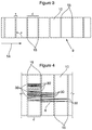
- is a top plan view of the collector in
Figure 2 ; - Figure 4
- is a top plan view of part of the collector in
Figure 2 in use; - Figure 5
- is a top plan view of the collector in
Figure 2 in use; - Figure 6
- is a top plan view a pre-yarn web produced by the collector in
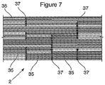
Figure 2 ; - Figure 7
- is a side elevation of part of a yarn produced using the apparatus in
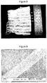
Figure 1 ; - Figure 8
- is a photograph of an unravelled section of yarn; and
- Figure 9
- is a scanning electron microscope (SEM) image of a yarn produced by the process.
- Apparatus (1) for producing a yarn (2) from nano-fibres is shown in
Figures 1 to 5 and includes an electrostatic spinning source (6) having a plurality of electrostatic spinning jets (4) with a fibre collector (9) spaced apart therefrom. In this embodiment the spinning source (6) is located 100mm below the collector (9). However, any suitable orientation could be used, including a top-down or side-by-side orientation, with a separating distance of between 0.5mm and 500mm. - The electrostatic spinning source (6) makes use of a traditional needle-based spinning apparatus, but could also use a multiple-needle setup, needleless spinning techniques, or any other electrostatic fibre-forming process. The apparatus (1) thus far described is of fairly conventional configuration.
- As shown in
Figures 2 and3 , the collector (9) includes an endless belt (10) supported between a pair of rollers (11, 12). One of the rollers (12) is driven so that the top of the belt (10) moves in the direction of the arrow (14). - According to the invention, the belt (10) has a plurality of conductive strips (15) thereon inclined at angle (θ) to its length, and hence the direction of movement of the belt (10). The conductive strips (15) are made from copper and each has a thickness (t) of between 100nm and 30mm. In this embodiment the thickness (t), or width, of each is uniform and is 1 mm (but shown on an exaggerated scale for illustrative purposes). The material of the belt (10), in this embodiment a rubberlike material, insulates the conductive strips (15) from each other along their length. However, the ends of the conductive strips (15) are conductively connected and maintained at ground potential.
- The inclination (θ) of the conductive strips (15) to the direction of movement of the belt (10) is between 5° and 175° and the distance (d) between each between 1µm and 300mm. In this embodiment the conductive strips (15) are parallel to each other and are inclined at 90° to the direction of movement of the belt (10) with a distance (d) of 10 mm between each. Also in this embodiment, the conductive strips (15) are of uniform height.
- An electric potential (20) is applied in conventional fashion between the nozzles (7) and conductive strips (15). In this embodiment the conductive strips (15) are held at electric ground potential.
- The belt (10) feeds onto web collector rollers (22, 23), which in turn feed into a web twister (25). Drawing rollers (26) and a take-up roller (28) are located after the twister (25) in conventional fashion.
- In use, nano-fibres (4) are electrostatically drawn to the conductive strips (15). As shown in
Figures 4 and5 , the fibres (4) each tend to span a pair or a number of adjacent conductive strips (15) by folding between these. The distance between each fold (30) for a fibre thus corresponds to the predetermined distance (d) between the conductive strips (15) and will either be equal to (d) or an integer multiple of (d). - The fibres (4) collected on the belt (10) are drawn off in conventional fashion by the web collector rollers (22, 23) and fed into the web twister (25), which forms the fibres (4) into a yarn (2). The drawing rollers (26) stretch the yarn (2) before it is collected on the take-up roller (28).
- The pre-yarn web (5a) prior to being fed in to the web twister (25) is shown in
Figure 6 and has the appearance of a sheet formed by a plurality of fibres which extend substantially in the direction of travel of the belt (10). The location of the folds (30) in the fibres which correspond to the conductive strips (15) are clearly visible as parallel lines (32) of high fibre density across the width of the web (5a). - This is also apparent from the photograph in
Figure 8 which shows a section of yarn which has been unravelled. The arrows indicate lines of higher fibre density which are caused by the folds in the fibres and which correspond to the conductive strips. The width of the higher density lines is determined by the thickness of the conductive strips on the collector. Even with conductive strips that are only 0.5mm thick these lines are clearly visible to the naked eye. The presence of these lines gives a clear indication that yarn was made using the process of the invention. - It will be appreciated that the fibres will generally not simply fold back on themselves to form a neat 180° bend but rather that each fold may be somewhat chaotic given the extremely thin diameter of each fibre compared to the thickness of the conductive strips and the rate at which the fibres are being produced (often in the order of kilometres per minute). Thus each fold may include a number of random loops or other random patterns which increases the fibre density at each conductive strip.
- An enlarged view of part of a yarn (2) produced by the apparatus (1) is shown in
Figure 7 . The folded fibres (35) are clearly visible with the folds (37) spaced the distance (d) or an integer multiple thereof apart. The spacing of the folds (37) is predeterminable as it reflects the spacing of the conductive strips (15). Importantly, the fibres are also uniformly oriented in the direction of the length of the yarn. - It has been found that the area where these folds occur is relatively large compared to the typical scale used in, for example, scanning electron microscopy (SEM) and are generally visible to the naked eye or under an optical microscope. However, SEM may be required to identify these lines in cases where the conductive strips are extremely thin and spaced very close to each other.
- A SEM image of a yarn produced by the process is shown in
Figure 9 . From this it will be noted that fibres show a high degree of alignment, much more so than with prior art industrial processes. - The alignment of the fibres in the yarn and the presence of regularly spaced folds in the fibres not only ensure easy identification of yarns produced by this process but also provide a yarn which is strong and is uniformly reproducible. These are surprising results from an apparently simple variation to known processes for producing nano-fibre yarns.
- It will be appreciated that many other processes and apparatuses exist which fall within the scope of the invention defined by the claims.
- For example, the conductive strips could be carried in any suitable manner, including on a rotating drum. Further alternately, the conductive strips could be secured by their ends between a pair of belts to have a ladder-like configuration with the conductive strips separated from each other by an air gap. The conductive strips could be separated by any suitable insulating material and need not be evenly spaced, parallel or of the same thickness. The conductive strips, being elongate conductive surfaces, can have any suitable configuration and could be made of any suitable material. For example, the conductive strips could be wire-like or tape-like or even provided by the edge of a plate or similar element.
- Clearly, the folds in the fibres found in the yarn will reflect the spacing of the will be found to repeat itself in the length of the yarn as the conductive strips move into and out of alignment with the electrostatic spinning fiber source.
- The electrostatic spinning source and fibre collector could be configured in any suitable manner, including for upward and sideward spinning, and any suitable number and configuration of spinning nozzles or needle-less sources can be used.
- Also, any suitable material, or combination of materials, can be used for making the nano-fibres.
Claims (18)
- A yarn spun from a plurality of nano-fibres, characterized in that at least some of the nano-fibres are folded with the folds occurring at distances predetermined by a plurality of moving conductive strips (15), the yarn obtainable by the process of electrostatically spinning a plurality of fibres onto a plurality of moving conductive strips (15) inclined to their direction of movement such that the fibres span the elongate conductive surfaces of at least some of the conductive strips (15), collecting the fibres from the conductive strips (15) and forming the fibres into the yarn.
- A yarn as claimed in claim 1 wherein the predeterminable distances are integer multiples of at least one specific spacing.
- A yarn as claimed in claim 1 or claim 2 wherein at least some fibres have a plurality of folds.
- A yarn as claimed in any one of the preceding claims wherein the fibres are aligned in substantially the same direction.
- A process for producing the yarn of claim 1 which includes electrostatically spinning a plurality of fibres onto a plurality of moving conductive strips (15) inclined to their direction of movement such that the fibres span at least some of the conductive strips (15), collecting the fibres from the conductive strips (15) and forming the fibres into a yarn.
- A process as claimed in claim 5 wherein the conductive strips (15) are separated from each other by an insulating gap.
- A process as claimed in claim 5 or 6 wherein the conductive strips (15) are parallel to each other.
- A process as claimed in claim 7 wherein the conductive strips (15) are spaced apart at predetermined equal distances of between 1µm and 300mm.
- A process as claimed in any one of claims 5 to 8 wherein the conductive strips (15) are inclined between 5° and 175° to their direction of movement, preferably 90° to their direction of movement
- A process as claimed in any one of claims 5 to 9 wherein the conductive strips (15) have a uniform thickness of between 100nm and 30mm.
- A process as claimed in claim 10 wherein the distance between the electrostatic spinning source (6) and the conductive strips (15) is between 0.5mm and 500mm and the electrostatic spinning source (6) and the conductive strips (15) are held at electric ground potential or at a potential with opposite polarity to that of the electrostatic spinning source.
- A process as claimed in any one of claims 5 to 11 wherein the fibres are formed into a yarn by mechanical or electrostatic means.
- Apparatus for producing a yarn including an electrostatic spinning source (6) and a plurality of conductive strips (15) arranged to collect fibres from the spinning source (6) and movable with respect thereto and a web collector and a web twister (25) arranged in series therewith, characterized in that the conductive strips (15) are inclined to their direction of movement such that the fibres span at least some of the conductive strips (15).
- Apparatus as claimed in claim 13 wherein the conductive strips (15) are carried on a moving surface.
- Apparatus as claimed in any one of claims 13 or 14 wherein the conductive strips (15) are parallel to each other.
- Apparatus as claimed in any one of claims 13 to 15 wherein the conductive strips (15) are spaced apart at predetermined equal distances of between 1µm and 300mm.
- Apparatus as claimed in any one of claims 13 to 16 wherein the conductive strips (15) are inclined between 5° and 175° to their direction of movement, preferably 90° to their direction of movement.
- Apparatus as claimed in any one of claims 13 to 17 wherein the conductive strips (15) have a uniform thickness of between 100nm and 30mm.
Applications Claiming Priority (3)
| Application Number | Priority Date | Filing Date | Title |
|---|---|---|---|
| ZA200609605 | 2006-11-20 | ||
| ZA200703634 | 2007-05-04 | ||
| PCT/IB2007/003177 WO2008062264A2 (en) | 2006-11-20 | 2007-10-23 | A yarn and a process for manufacture thereof |
Publications (2)
| Publication Number | Publication Date |
|---|---|
| EP2092095A2 EP2092095A2 (en) | 2009-08-26 |
| EP2092095B1 true EP2092095B1 (en) | 2017-03-08 |
Family
ID=39430104
Family Applications (1)
| Application Number | Title | Priority Date | Filing Date |
|---|---|---|---|
| EP07825465.3A Not-in-force EP2092095B1 (en) | 2006-11-20 | 2007-10-23 | A yarn and a process for manufacture thereof |
Country Status (3)
| Country | Link |
|---|---|
| US (1) | US8522520B2 (en) |
| EP (1) | EP2092095B1 (en) |
| WO (1) | WO2008062264A2 (en) |
Families Citing this family (16)
| Publication number | Priority date | Publication date | Assignee | Title |
|---|---|---|---|---|
| AU2008237631B2 (en) | 2007-04-17 | 2011-10-13 | Stellenbosch University | A process for the production of fibres |
| CZ2007727A3 (en) * | 2007-10-18 | 2009-04-29 | Nanopeutics S. R. O. | Collecting electrode of a device for producing nanofibers by electrostatic spinning of polymer matrices and device comprising such collecting electrode |
| CZ2007728A3 (en) * | 2007-10-18 | 2009-04-29 | Elmarco S. R. O. | Apparatus for producing a layer of nanofibers by electrostatic spinning of polymer matrices |
| GB2494277A (en) | 2011-08-29 | 2013-03-06 | Univ Heriot Watt | Electro-spinning nanofibres onto a moving wire card |
| WO2015011768A1 (en) * | 2013-07-22 | 2015-01-29 | 村田機械株式会社 | Yarn manufacturing device |
| US10351977B2 (en) * | 2013-07-22 | 2019-07-16 | Murata Machinery, Ltd. | Thread production device |
| JP6015861B2 (en) * | 2013-07-22 | 2016-10-26 | 村田機械株式会社 | Yarn manufacturing equipment |
| GB201316577D0 (en) | 2013-09-18 | 2013-10-30 | Isis Innovation | Electrospun filaments |
| WO2015075658A1 (en) | 2013-11-20 | 2015-05-28 | The Stellenbosch Nanofiber Company (Pty) Limited | Electrospun fibre collection and handling |
| CZ2014947A3 (en) | 2014-12-22 | 2016-06-22 | Technická univerzita v Liberci | Process for producing textile composite material containing polymeric nanofibers and textile composite material containing polymeric nanofibers |
| KR101885822B1 (en) * | 2016-07-26 | 2018-09-06 | 전북대학교산학협력단 | Roll to roll type apparatus for manufacturing transparent nano fiber |
| WO2018162950A1 (en) | 2017-03-07 | 2018-09-13 | The Stellenbosch Nanofiber Company (Pty) Ltd | Apparatus and method for the production of fine fibers |
| JP6818669B2 (en) * | 2017-09-25 | 2021-01-20 | 株式会社東芝 | Electric field spinning equipment |
| JP2022551865A (en) | 2019-10-07 | 2022-12-14 | ザ ステレンボッシュ ナノファイバー カンパニー(ピーティーワイ)リミテッド | Method for preparing cosmetic ingredients |
| JP7689302B2 (en) * | 2021-05-19 | 2025-06-06 | パナソニックIpマネジメント株式会社 | Fiber assembly manufacturing apparatus and method |
| CZ2022370A3 (en) * | 2022-09-02 | 2024-03-13 | Technická univerzita v Liberci | A method of producing nanofibrous yarn by alternating electrospinning of a polymer solution or melt and a device for carrying out the method |
Citations (1)
| Publication number | Priority date | Publication date | Assignee | Title |
|---|---|---|---|---|
| DE689870C (en) * | 1937-08-19 | 1940-04-08 | Anton Formhals Dipl Ing | Process for the production of artificial fibers from fiber-forming fluids, in particular acetyl cellulose |
Family Cites Families (16)
| Publication number | Priority date | Publication date | Assignee | Title |
|---|---|---|---|---|
| US692631A (en) | 1899-10-06 | 1902-02-04 | Charles S Farquhar | Apparatus for electrically dispersing fluids. |
| US1975504A (en) | 1929-12-07 | 1934-10-02 | Richard Schreiber Gastell | Process and apparatus for preparing artificial threads |
| US2109333A (en) | 1936-03-04 | 1938-02-22 | Richard Schreiber Gastell | Artificial fiber construction |
| US2123992A (en) | 1936-07-01 | 1938-07-19 | Richard Schreiber Gastell | Method and apparatus for the production of fibers |
| US2187306A (en) | 1937-07-28 | 1940-01-16 | Richard Schreiber Gastell | Artificial thread and method of producing same |
| US2349950A (en) | 1937-08-18 | 1944-05-30 | Formhals Anton | Method and apparatus for spinning |
| US6106913A (en) * | 1997-10-10 | 2000-08-22 | Quantum Group, Inc | Fibrous structures containing nanofibrils and other textile fibers |
| KR100491228B1 (en) | 2003-02-24 | 2005-05-24 | 김학용 | A process of preparing continuous filament composed of nano fiber |
| US20090189319A1 (en) | 2004-02-02 | 2009-07-30 | Kim Hak-Yong | Process of preparing continuous filament composed of nanofibers |
| US20080241538A1 (en) | 2004-06-17 | 2008-10-02 | Korea Research Institute Of Chemical Technology | Filament Bundle Type Nano Fiber and Manufacturing Method Thereof |
| CN108425170B (en) * | 2004-11-09 | 2021-02-26 | 得克萨斯大学体系董事会 | Manufacture and use of nanofiber yarns, tapes and sheets |
| WO2006052039A1 (en) | 2004-11-12 | 2006-05-18 | Hak-Yong Kim | A process of preparing continuos filament composed of nano fibers |
| CN100334268C (en) | 2005-03-25 | 2007-08-29 | 东南大学 | Method for preparing nano fiber endless tow |
| KR100621428B1 (en) | 2005-06-17 | 2006-09-07 | 전북대학교산학협력단 | Method for manufacturing continuous phase filament using electrospinning and continuous filament manufactured therefrom |
| CN100427652C (en) | 2005-11-11 | 2008-10-22 | 东南大学 | Composite nanofiber filament bundle preparation device and preparation method thereof |
| CN100390332C (en) | 2005-11-25 | 2008-05-28 | 清华大学 | Electric device and method for spinning generation and collection |
-
2007
- 2007-10-23 EP EP07825465.3A patent/EP2092095B1/en not_active Not-in-force
- 2007-10-23 WO PCT/IB2007/003177 patent/WO2008062264A2/en not_active Ceased
- 2007-10-23 US US12/515,513 patent/US8522520B2/en not_active Expired - Fee Related
Patent Citations (1)
| Publication number | Priority date | Publication date | Assignee | Title |
|---|---|---|---|---|
| DE689870C (en) * | 1937-08-19 | 1940-04-08 | Anton Formhals Dipl Ing | Process for the production of artificial fibers from fiber-forming fluids, in particular acetyl cellulose |
Also Published As
| Publication number | Publication date |
|---|---|
| US20110247311A1 (en) | 2011-10-13 |
| WO2008062264A2 (en) | 2008-05-29 |
| EP2092095A2 (en) | 2009-08-26 |
| WO2008062264A3 (en) | 2008-10-30 |
| US8522520B2 (en) | 2013-09-03 |
Similar Documents
| Publication | Publication Date | Title |
|---|---|---|
| US8522520B2 (en) | Yarn and a process for manufacture thereof | |
| Zhou et al. | Manufacturing technologies of polymeric nanofibres and nanofibre yarns | |
| Bazbouz et al. | Alignment and optimization of nylon 6 nanofibers by electrospinning | |
| Baji et al. | Electrospinning of polymer nanofibers: Effects on oriented morphology, structures and tensile properties | |
| US20140331455A1 (en) | Method and machinery for making nanofibres | |
| CN106835412B (en) | Method and device for twisting electrostatic spinning nanofiber into yarn | |
| Dabirian et al. | Novel method for nanofibre yarn production using two differently charged nozzles | |
| US20080102145A1 (en) | Conjugate Electrospinning Devices, Conjugate Nonwoven and Filament Comprising Nanofibers Prepared by Using the Same | |
| CN105220246B (en) | A kind of multiply jet friction of electrostatic spinning nano fiber is into yarn feeding device and preparation method | |
| Su et al. | Yarn formation of nanofibers prepared using electrospinning | |
| CN103132194A (en) | Orientation electro-spinning nanometer fiber spinning method and device thereof | |
| CN101280468B (en) | Multi-needle V-shaped groove drum electrostatic spinning system and preparation of nano-fiber tuft | |
| Sanatgar et al. | The influence of solvent type and polymer concentration on the physical properties of solid state polymerized PA66 nanofiber yarn | |
| He et al. | Multineedle electrospinning | |
| CN101037809A (en) | Continuously static spinning method of polyamide 6/66 copolymer filament yarn | |
| Göktepe et al. | Long path towards to success in electrospun nanofiber yarn production since 1930’s: a critical review | |
| KR100621428B1 (en) | Method for manufacturing continuous phase filament using electrospinning and continuous filament manufactured therefrom | |
| Ali et al. | Electrospinning of continuous nanofiber bundles and twisted nanofiber yarns | |
| CN101589182B (en) | A yarn and a process for manufacture thereof | |
| CN104711719A (en) | Rotating collector for preparing electrospinning nanofiber yarn device and its preparation method | |
| Mondal et al. | Electrospun self‐assembled nanofiber yarns | |
| Zhou et al. | Developments in electrospinning of nanofiber yarns | |
| WO2015075658A1 (en) | Electrospun fibre collection and handling | |
| Chvojka et al. | Production of poly (vinylalcohol) nanoyarns using a special saw-like collector | |
| Yeum et al. | Fabrication of highly aligned poly (vinyl alcohol) nanofibers and its yarn by electrospinning |
Legal Events
| Date | Code | Title | Description |
|---|---|---|---|
| PUAI | Public reference made under article 153(3) epc to a published international application that has entered the european phase |
Free format text: ORIGINAL CODE: 0009012 |
|
| 17P | Request for examination filed |
Effective date: 20090619 |
|
| AK | Designated contracting states |
Kind code of ref document: A2 Designated state(s): AT BE BG CH CY CZ DE DK EE ES FI FR GB GR HU IE IS IT LI LT LU LV MC MT NL PL PT RO SE SI SK TR |
|
| DAX | Request for extension of the european patent (deleted) | ||
| 17Q | First examination report despatched |
Effective date: 20120112 |
|
| GRAP | Despatch of communication of intention to grant a patent |
Free format text: ORIGINAL CODE: EPIDOSNIGR1 |
|
| INTG | Intention to grant announced |
Effective date: 20160916 |
|
| STAA | Information on the status of an ep patent application or granted ep patent |
Free format text: STATUS: GRANT OF PATENT IS INTENDED |
|
| GRAS | Grant fee paid |
Free format text: ORIGINAL CODE: EPIDOSNIGR3 |
|
| GRAA | (expected) grant |
Free format text: ORIGINAL CODE: 0009210 |
|
| STAA | Information on the status of an ep patent application or granted ep patent |
Free format text: STATUS: THE PATENT HAS BEEN GRANTED |
|
| AK | Designated contracting states |
Kind code of ref document: B1 Designated state(s): AT BE BG CH CY CZ DE DK EE ES FI FR GB GR HU IE IS IT LI LT LU LV MC MT NL PL PT RO SE SI SK TR |
|
| REG | Reference to a national code |
Ref country code: GB Ref legal event code: FG4D |
|
| REG | Reference to a national code |
Ref country code: CH Ref legal event code: EP Ref country code: AT Ref legal event code: REF Ref document number: 873608 Country of ref document: AT Kind code of ref document: T Effective date: 20170315 |
|
| REG | Reference to a national code |
Ref country code: IE Ref legal event code: FG4D |
|
| REG | Reference to a national code |
Ref country code: DE Ref legal event code: R096 Ref document number: 602007050106 Country of ref document: DE |
|
| REG | Reference to a national code |
Ref country code: NL Ref legal event code: FP |
|
| REG | Reference to a national code |
Ref country code: LT Ref legal event code: MG4D |
|
| PG25 | Lapsed in a contracting state [announced via postgrant information from national office to epo] |
Ref country code: FI Free format text: LAPSE BECAUSE OF FAILURE TO SUBMIT A TRANSLATION OF THE DESCRIPTION OR TO PAY THE FEE WITHIN THE PRESCRIBED TIME-LIMIT Effective date: 20170308 Ref country code: GR Free format text: LAPSE BECAUSE OF FAILURE TO SUBMIT A TRANSLATION OF THE DESCRIPTION OR TO PAY THE FEE WITHIN THE PRESCRIBED TIME-LIMIT Effective date: 20170609 Ref country code: LT Free format text: LAPSE BECAUSE OF FAILURE TO SUBMIT A TRANSLATION OF THE DESCRIPTION OR TO PAY THE FEE WITHIN THE PRESCRIBED TIME-LIMIT Effective date: 20170308 |
|
| REG | Reference to a national code |
Ref country code: AT Ref legal event code: MK05 Ref document number: 873608 Country of ref document: AT Kind code of ref document: T Effective date: 20170308 |
|
| PG25 | Lapsed in a contracting state [announced via postgrant information from national office to epo] |
Ref country code: BG Free format text: LAPSE BECAUSE OF FAILURE TO SUBMIT A TRANSLATION OF THE DESCRIPTION OR TO PAY THE FEE WITHIN THE PRESCRIBED TIME-LIMIT Effective date: 20170608 Ref country code: ES Free format text: LAPSE BECAUSE OF FAILURE TO SUBMIT A TRANSLATION OF THE DESCRIPTION OR TO PAY THE FEE WITHIN THE PRESCRIBED TIME-LIMIT Effective date: 20170308 Ref country code: SE Free format text: LAPSE BECAUSE OF FAILURE TO SUBMIT A TRANSLATION OF THE DESCRIPTION OR TO PAY THE FEE WITHIN THE PRESCRIBED TIME-LIMIT Effective date: 20170308 Ref country code: LV Free format text: LAPSE BECAUSE OF FAILURE TO SUBMIT A TRANSLATION OF THE DESCRIPTION OR TO PAY THE FEE WITHIN THE PRESCRIBED TIME-LIMIT Effective date: 20170308 |
|
| PG25 | Lapsed in a contracting state [announced via postgrant information from national office to epo] |
Ref country code: IT Free format text: LAPSE BECAUSE OF FAILURE TO SUBMIT A TRANSLATION OF THE DESCRIPTION OR TO PAY THE FEE WITHIN THE PRESCRIBED TIME-LIMIT Effective date: 20170308 Ref country code: SK Free format text: LAPSE BECAUSE OF FAILURE TO SUBMIT A TRANSLATION OF THE DESCRIPTION OR TO PAY THE FEE WITHIN THE PRESCRIBED TIME-LIMIT Effective date: 20170308 Ref country code: AT Free format text: LAPSE BECAUSE OF FAILURE TO SUBMIT A TRANSLATION OF THE DESCRIPTION OR TO PAY THE FEE WITHIN THE PRESCRIBED TIME-LIMIT Effective date: 20170308 Ref country code: RO Free format text: LAPSE BECAUSE OF FAILURE TO SUBMIT A TRANSLATION OF THE DESCRIPTION OR TO PAY THE FEE WITHIN THE PRESCRIBED TIME-LIMIT Effective date: 20170308 Ref country code: EE Free format text: LAPSE BECAUSE OF FAILURE TO SUBMIT A TRANSLATION OF THE DESCRIPTION OR TO PAY THE FEE WITHIN THE PRESCRIBED TIME-LIMIT Effective date: 20170308 |
|
| PG25 | Lapsed in a contracting state [announced via postgrant information from national office to epo] |
Ref country code: IS Free format text: LAPSE BECAUSE OF FAILURE TO SUBMIT A TRANSLATION OF THE DESCRIPTION OR TO PAY THE FEE WITHIN THE PRESCRIBED TIME-LIMIT Effective date: 20170708 Ref country code: PL Free format text: LAPSE BECAUSE OF FAILURE TO SUBMIT A TRANSLATION OF THE DESCRIPTION OR TO PAY THE FEE WITHIN THE PRESCRIBED TIME-LIMIT Effective date: 20170308 Ref country code: PT Free format text: LAPSE BECAUSE OF FAILURE TO SUBMIT A TRANSLATION OF THE DESCRIPTION OR TO PAY THE FEE WITHIN THE PRESCRIBED TIME-LIMIT Effective date: 20170710 |
|
| REG | Reference to a national code |
Ref country code: DE Ref legal event code: R097 Ref document number: 602007050106 Country of ref document: DE |
|
| PLBE | No opposition filed within time limit |
Free format text: ORIGINAL CODE: 0009261 |
|
| STAA | Information on the status of an ep patent application or granted ep patent |
Free format text: STATUS: NO OPPOSITION FILED WITHIN TIME LIMIT |
|
| PG25 | Lapsed in a contracting state [announced via postgrant information from national office to epo] |
Ref country code: DK Free format text: LAPSE BECAUSE OF FAILURE TO SUBMIT A TRANSLATION OF THE DESCRIPTION OR TO PAY THE FEE WITHIN THE PRESCRIBED TIME-LIMIT Effective date: 20170308 |
|
| PGFP | Annual fee paid to national office [announced via postgrant information from national office to epo] |
Ref country code: TR Payment date: 20171023 Year of fee payment: 11 |
|
| 26N | No opposition filed |
Effective date: 20171211 |
|
| PG25 | Lapsed in a contracting state [announced via postgrant information from national office to epo] |
Ref country code: SI Free format text: LAPSE BECAUSE OF FAILURE TO SUBMIT A TRANSLATION OF THE DESCRIPTION OR TO PAY THE FEE WITHIN THE PRESCRIBED TIME-LIMIT Effective date: 20170308 |
|
| PGFP | Annual fee paid to national office [announced via postgrant information from national office to epo] |
Ref country code: NL Payment date: 20171023 Year of fee payment: 11 Ref country code: GB Payment date: 20171024 Year of fee payment: 11 |
|
| PG25 | Lapsed in a contracting state [announced via postgrant information from national office to epo] |
Ref country code: MC Free format text: LAPSE BECAUSE OF FAILURE TO SUBMIT A TRANSLATION OF THE DESCRIPTION OR TO PAY THE FEE WITHIN THE PRESCRIBED TIME-LIMIT Effective date: 20170308 |
|
| REG | Reference to a national code |
Ref country code: CH Ref legal event code: PL |
|
| REG | Reference to a national code |
Ref country code: IE Ref legal event code: MM4A |
|
| REG | Reference to a national code |
Ref country code: FR Ref legal event code: ST Effective date: 20180629 |
|
| PG25 | Lapsed in a contracting state [announced via postgrant information from national office to epo] |
Ref country code: LI Free format text: LAPSE BECAUSE OF NON-PAYMENT OF DUE FEES Effective date: 20171031 Ref country code: CH Free format text: LAPSE BECAUSE OF NON-PAYMENT OF DUE FEES Effective date: 20171031 Ref country code: LU Free format text: LAPSE BECAUSE OF NON-PAYMENT OF DUE FEES Effective date: 20171023 |
|
| REG | Reference to a national code |
Ref country code: BE Ref legal event code: MM Effective date: 20171031 |
|
| PG25 | Lapsed in a contracting state [announced via postgrant information from national office to epo] |
Ref country code: FR Free format text: LAPSE BECAUSE OF NON-PAYMENT OF DUE FEES Effective date: 20171031 Ref country code: BE Free format text: LAPSE BECAUSE OF NON-PAYMENT OF DUE FEES Effective date: 20171031 |
|
| PG25 | Lapsed in a contracting state [announced via postgrant information from national office to epo] |
Ref country code: MT Free format text: LAPSE BECAUSE OF NON-PAYMENT OF DUE FEES Effective date: 20171023 |
|
| PG25 | Lapsed in a contracting state [announced via postgrant information from national office to epo] |
Ref country code: IE Free format text: LAPSE BECAUSE OF NON-PAYMENT OF DUE FEES Effective date: 20171023 |
|
| PGFP | Annual fee paid to national office [announced via postgrant information from national office to epo] |
Ref country code: DE Payment date: 20181024 Year of fee payment: 12 Ref country code: CZ Payment date: 20181113 Year of fee payment: 12 |
|
| REG | Reference to a national code |
Ref country code: NL Ref legal event code: MM Effective date: 20181101 |
|
| GBPC | Gb: european patent ceased through non-payment of renewal fee |
Effective date: 20181023 |
|
| PG25 | Lapsed in a contracting state [announced via postgrant information from national office to epo] |
Ref country code: HU Free format text: LAPSE BECAUSE OF FAILURE TO SUBMIT A TRANSLATION OF THE DESCRIPTION OR TO PAY THE FEE WITHIN THE PRESCRIBED TIME-LIMIT; INVALID AB INITIO Effective date: 20071023 |
|
| PG25 | Lapsed in a contracting state [announced via postgrant information from national office to epo] |
Ref country code: NL Free format text: LAPSE BECAUSE OF NON-PAYMENT OF DUE FEES Effective date: 20181101 |
|
| PG25 | Lapsed in a contracting state [announced via postgrant information from national office to epo] |
Ref country code: GB Free format text: LAPSE BECAUSE OF NON-PAYMENT OF DUE FEES Effective date: 20181023 Ref country code: CY Free format text: LAPSE BECAUSE OF NON-PAYMENT OF DUE FEES Effective date: 20170308 |
|
| REG | Reference to a national code |
Ref country code: DE Ref legal event code: R119 Ref document number: 602007050106 Country of ref document: DE |
|
| PG25 | Lapsed in a contracting state [announced via postgrant information from national office to epo] |
Ref country code: DE Free format text: LAPSE BECAUSE OF NON-PAYMENT OF DUE FEES Effective date: 20200501 Ref country code: CZ Free format text: LAPSE BECAUSE OF NON-PAYMENT OF DUE FEES Effective date: 20191023 |
|
| PG25 | Lapsed in a contracting state [announced via postgrant information from national office to epo] |
Ref country code: TR Free format text: LAPSE BECAUSE OF NON-PAYMENT OF DUE FEES Effective date: 20181023 |