EP2091300B1 - Cooking device - Google Patents
Cooking device Download PDFInfo
- Publication number
- EP2091300B1 EP2091300B1 EP09250313.5A EP09250313A EP2091300B1 EP 2091300 B1 EP2091300 B1 EP 2091300B1 EP 09250313 A EP09250313 A EP 09250313A EP 2091300 B1 EP2091300 B1 EP 2091300B1
- Authority
- EP
- European Patent Office
- Prior art keywords
- electromagnetic generating
- cooking device
- electromagnetic
- plate
- sections
- Prior art date
- Legal status (The legal status is an assumption and is not a legal conclusion. Google has not performed a legal analysis and makes no representation as to the accuracy of the status listed.)
- Active
Links
- 238000010411 cooking Methods 0.000 title claims description 85
- 238000005192 partition Methods 0.000 claims description 48
- 238000010438 heat treatment Methods 0.000 claims description 41
- 230000001105 regulatory effect Effects 0.000 claims description 36
- 238000007664 blowing Methods 0.000 claims description 34
- 238000009423 ventilation Methods 0.000 claims description 28
- 238000003780 insertion Methods 0.000 claims description 24
- 230000037431 insertion Effects 0.000 claims description 24
- 238000001816 cooling Methods 0.000 claims description 20
- 230000000903 blocking effect Effects 0.000 claims description 6
- 230000008901 benefit Effects 0.000 description 19
- 230000000694 effects Effects 0.000 description 10
- 238000000926 separation method Methods 0.000 description 8
- 238000012423 maintenance Methods 0.000 description 7
- 229910052782 aluminium Inorganic materials 0.000 description 5
- XAGFODPZIPBFFR-UHFFFAOYSA-N aluminium Chemical compound [Al] XAGFODPZIPBFFR-UHFFFAOYSA-N 0.000 description 5
- 239000007787 solid Substances 0.000 description 5
- 229910052751 metal Inorganic materials 0.000 description 4
- 239000002184 metal Substances 0.000 description 4
- 230000004907 flux Effects 0.000 description 2
- 239000007788 liquid Substances 0.000 description 2
- 239000010445 mica Substances 0.000 description 2
- 229910052618 mica group Inorganic materials 0.000 description 2
- 230000000149 penetrating effect Effects 0.000 description 2
- 238000005452 bending Methods 0.000 description 1
- 239000004020 conductor Substances 0.000 description 1
- 230000003247 decreasing effect Effects 0.000 description 1
- 238000007599 discharging Methods 0.000 description 1
- 238000006073 displacement reaction Methods 0.000 description 1
- 230000005284 excitation Effects 0.000 description 1
- 235000013410 fast food Nutrition 0.000 description 1
- 235000013305 food Nutrition 0.000 description 1
- 239000000463 material Substances 0.000 description 1
- 238000000034 method Methods 0.000 description 1
- 238000012986 modification Methods 0.000 description 1
- 230000004048 modification Effects 0.000 description 1
- 238000013021 overheating Methods 0.000 description 1
- 230000002265 prevention Effects 0.000 description 1
- 230000005855 radiation Effects 0.000 description 1
- 230000008439 repair process Effects 0.000 description 1
- 239000011347 resin Substances 0.000 description 1
- 229920005989 resin Polymers 0.000 description 1
- 238000010257 thawing Methods 0.000 description 1
- 230000001131 transforming effect Effects 0.000 description 1
Images


Classifications
-
- H—ELECTRICITY
- H05—ELECTRIC TECHNIQUES NOT OTHERWISE PROVIDED FOR
- H05B—ELECTRIC HEATING; ELECTRIC LIGHT SOURCES NOT OTHERWISE PROVIDED FOR; CIRCUIT ARRANGEMENTS FOR ELECTRIC LIGHT SOURCES, IN GENERAL
- H05B6/00—Heating by electric, magnetic or electromagnetic fields
- H05B6/64—Heating using microwaves
- H05B6/72—Radiators or antennas
- H05B6/725—Rotatable antennas
-
- F—MECHANICAL ENGINEERING; LIGHTING; HEATING; WEAPONS; BLASTING
- F24—HEATING; RANGES; VENTILATING
- F24C—DOMESTIC STOVES OR RANGES ; DETAILS OF DOMESTIC STOVES OR RANGES, OF GENERAL APPLICATION
- F24C15/00—Details
- F24C15/006—Arrangements for circulation of cooling air
-
- H—ELECTRICITY
- H05—ELECTRIC TECHNIQUES NOT OTHERWISE PROVIDED FOR
- H05B—ELECTRIC HEATING; ELECTRIC LIGHT SOURCES NOT OTHERWISE PROVIDED FOR; CIRCUIT ARRANGEMENTS FOR ELECTRIC LIGHT SOURCES, IN GENERAL
- H05B6/00—Heating by electric, magnetic or electromagnetic fields
- H05B6/64—Heating using microwaves
- H05B6/642—Cooling of the microwave components and related air circulation systems
-
- H—ELECTRICITY
- H05—ELECTRIC TECHNIQUES NOT OTHERWISE PROVIDED FOR
- H05B—ELECTRIC HEATING; ELECTRIC LIGHT SOURCES NOT OTHERWISE PROVIDED FOR; CIRCUIT ARRANGEMENTS FOR ELECTRIC LIGHT SOURCES, IN GENERAL
- H05B2206/00—Aspects relating to heating by electric, magnetic, or electromagnetic fields covered by group H05B6/00
- H05B2206/04—Heating using microwaves
- H05B2206/044—Microwave heating devices provided with two or more magnetrons or microwave sources of other kind
Definitions
- the domestic-use cooking device provides one magnetron, and is configured to emit microwave generated by the magnetron to the heating chamber, with propagation of the microwave through one wave guide.
- the business-use cooking device provides: one pair of magnetrons that are laterally spaced apart each other and arranged in parallel on one side of an upper portion of a heating chamber; two wave guides that are arranged on upper sides of the respective magnetrons; two fans that are arranged on lower sides of the respective magnetrons; and two blowing paths that guide air, which is flown by the respective fans, around the respective magnetrons.
- the business-use cooking device is configured to emit microwave generated by the pair of magnetrons to the heating chamber, with propagation of the microwave through two wave guides (e.g. Japanese Patent Application Laid-Open No. 5-322187 ).
- the insulating plate is supported by insertion into a gap between the second partition plate and the air regulating plate. It is thus possible to insert the insulating plate for support into a gap between the second partition plate and the air regulating plate. Furthermore, it is possible to pull out the insulating plate from the gap between the second partition plate and the air regulating plate. Therefore, the cooking device has an advantage to improve maintenance actions, because of facilitating to mount/demount the insulating plate when mounting/demounting the electromagnetic generating unit for maintenance.
- the second partition plate is spaced apart vertically and laterally from an edge of the aperture area. It is thus possible to insert the insulating plate inside of the regulating plate through a gap between the second partition plate and the edge of the aperture area, even though lateral distance between the second partition plate and one air regulating plate is different from lateral distance between the second partition plate and another air regulating plate, by transforming the insulating plate which is arranged on a shorter-lateral distance side. Therefore, the cooking device has an advantage to enhance operability for mounting the insulating plate.
- the covering member 11d provides grille-shaped first and second exhaust ports 1g, 1h at front portions of the both lateral sides (cf. FIG. 5 ).
Description
- The present invention relates to a cooking device that heats an object, such as a microwave oven.
- Japanese Patent Application Laid-Open No.
5-322187 - A cooking device for domestic use is known to be arranged in a household kitchen and to be used by household members. In addition, a cooking device for buisiness use is known to be arranged in a kitchen of hotel, restrant, fast food shop, or the like, and to be used by kitchen staffs or the like for serving a dish or food to a customer. The business-use cooking device requires relatively large calorific power to heat an object within shrot-time, because the device is frequently used during opening time for business in order to respond immediately to customer demands. As opposed to the business-use cooking device, the domestic-use cooking device does not require such a relatively large calorific power to heat an object, because the device is used only a several times a day.
- Accordingly, the domestic-use cooking device provides one magnetron, and is configured to emit microwave generated by the magnetron to the heating chamber, with propagation of the microwave through one wave guide. On the other hand, the business-use cooking device provides: one pair of magnetrons that are laterally spaced apart each other and arranged in parallel on one side of an upper portion of a heating chamber; two wave guides that are arranged on upper sides of the respective magnetrons; two fans that are arranged on lower sides of the respective magnetrons; and two blowing paths that guide air, which is flown by the respective fans, around the respective magnetrons. Further, the business-use cooking device is configured to emit microwave generated by the pair of magnetrons to the heating chamber, with propagation of the microwave through two wave guides (e.g. Japanese Patent Application Laid-Open No.
5-322187 -
US 5,451,751 discloses a high-frequency heating apparatus capable of heating uniformly a liquid load, having an economical wave guide switching unit and having a compact-sized and economical power circuit to drive a plurality of magnetrons. The high-frequency heating apparatus includes an excitation opening, provided at the bottom of a heating chamber for radiating microwaves to heat the liquid load in a container, a magnetron for generating the microwave to heat the object and a wave guide connected to a magnetron. The apparatus further includes a wave guide switching unity for switching the propagation of the microwave to one of plural wave guides. The switching unit includes a pair of circular conductive plates and a conductor disposed in the vicinity of a circumference of the circular conductive plate so as to shut off the microwave, wherein there is constructed a choke structure on the wave guide containing the circular conductive plates. The apparatus further includes a magnetron drive circuit including a filament heating power supply connected to each filament of the magnetrons, a high voltage generating element and a switching element for selectively supplying a high voltage from the high voltage generating element to an anode of the magnetrons -
EP 0,091,779 discloses a microwave heater suitable for use for thawing frozen cake uniformly and in a shorter time. The frozen cake is placed on a high-frequency transmissive resin tray having at the bottom thereof an aluminum plate, and the cake is covered by a cup-shaped aluminum container. The cup-shaped aluminum contained and the aluminum plate are respectively provided with a plurality of apertures, and the radiation of the microwave to the frozen cake is controlled with respect to the amount and direction of introduction by selecting the sizes and positions of the apertures of the cup-shapes contained and the aluminum plate. - However, in a cooking device providing the one pair of magnetrons that are laterally spaced apart and arranged in parallel on one side of an upper portion of a heating chamber as shown in Japanese Patent Application Laid-Open No.
5-322187 - When one of the two magnetrons is broken, the cooking device having the two magnetrons cannot heat an object properly because of insufficient calorific power. Then, such a broken magnetron should be repaired or replaced to recover sufficient calorific power for the cooking device. Therefore, there is another concern that the cooking device cannot cook an object properly and respond to a demand for cooking, during the repair or replace.
- The present invention was made in view of such a circumstance, and has a primary object to provide a cooking device in which a first electromagnetic generating unit and a second electromagnetic generating unit are spaced apart in an up-and-down direction and a first blowing path and a second blowing path for guiding air, which are flown by fans, around the respective electromagnetic generating units are provided, so as to allow equalization of two cooling effects on the two electromagnetic generating units, and enhancement of durability of the respective electromagnetic generating units.
- According to the present invention there is provided a cooking device comprising: a first electromagnetic generating unit and a second electromagnetic generating unit for generating electromagnetic waves to cook; a heating chamber for introducing the electromagnetic waves generated by the first and the second electromagnetic generating units, to heat an object; fans for cooling the first and the second electromagnetic generating units, respectively; and a first blowing path and a second blowing path for blowing respective air flown by the fans around the first and the second electromagnetic generating units respectively, characterized in that: the first electromagnetic generating unit is arranged in an upper position and the second electromagnetic generating unit is arranged in a lower position, wherein each of the first and the second electromagnetic generating unit vertically comprises: an electromagnetic generating section; and a driving section for driving the electromagnetic generating section, the driving sections are opposed each other, in an up-and-down direction, and the electromagnetic generating sections and the driving sections are vertically collinear.
- In the cooking device according to the first aspect, a distance between the first and the second electromagnetic generating units can be made relatively long, while the first and the second electromagnetic generating units are arranged above and below of the cooking device. Therefore, the cooking device has an advantage to reduce an influence of "heat of air" that has cooled one of the two electromagnetic generating units on the other electromagnetic generating unit. Furthermore, in the cooking device, air blown through the first and the second blowing paths can cool the first and the second electromagnetic generating units, respectively and equally. Therefore, it is possible to equalize two cooling effects on the two electromagnetic generating units. Thus, the cooking device has an advantage to enhance durability of the respective electromagnetic generating units.
- A distance between the electromagnetic generating sections of the first and the second electromagnetic generating units can be made further longer, while the first and the second electromagnetic generating units are arranged above and below of the cooking device. Therefore, the cooking device has an advantage to reduce an influence of "heat of air" that has cooled one of the two electromagnetic generating units on the other electromagnetic generating unit, more significantly. Furthermore, in the cooking device, air blown through the first and the second blowing paths can cool the first and the second electromagnetic generating units, respectively and more equally. Therefore, the cooking device has an advantage to equalize two cooling effects on the two electromagnetic generating units, more preferably.
- Preferably the cooking device further comprises: a ventilation duct that surrounds both lateral peripheries of the first and the second electromagnetic generating units; and a partition wall that vertically divides an inside of the ventilation duct into a potion for the driving section and a portion for the electromagnetic generating section of each of the first and the second electromagnetic wave generating unit.
It is possible to blow air intensively to the electromagnetic generating sections, while the electromagnetic generating sections generally become higher temperatures than the driving sections. Therefore, the cooking device has an advantage to cool intensively the each of the electromagnetic generating sections, which leads further preferable equalization of two cooling effects on the two electromagnetic generating units. - Preferably the partition wall comprises: a first partition plate that extends in an up-and-down direction on both lateral sides of the driving sections of both the first and the second electromagnetic generating units; and a second partition plate that extends laterally from the first partition plate.
It is therefore possible to form the first partition plate and second partition plate in one ventilation duct. Therefore, the cooking device has an advantage to improve efficiency of maintenance actions, because a first blowing path and a second blowing path can be provided by incorporating the ventilation duct. - Preferably the cooking device further comprises: an insulating plate that extends in an up-and-down direction on a lateral side of the driving sections of both the first and the second electromagnetic generating units, wherein the insulating plate has an insertion hole; and a power supply line that is connected to the driving sections of both the first and the second electromagnetic generating units, through the insertion hole.
The cooking device has an advantage to prevent electric leak from the power supply line to the ventilation duct side. - Preferably the insulating plate forms a part of the ventilation duct.
This provides an advantage to simplify a configuration around the ventilation duct because of a part of the ventilation duct having the insulating plate, which leads to improve an assembly operation more preferably. - It is preferred that each of the driving section comprises a power supply terminal that is protruding laterally, the ventilation duct comprises: an air regulating plate that is arranged on both lateral sides of the electromagnetic generating sections of both the first and the second electromagnetic generating units, wherein the air regulating plate has an aperture area that is arranged correspondingly to an arrangement of the power supply terminals, the insulating plate is superimposed on the air regulating plate, and the insertion hole is opened laterally on the basis of a position of the power supply terminal.
It is thus possible to mount and demount the insulating plate without demounting the power supply line connected to a power supply terminal, which keeps the insulating plate being mounted without tension and stress. Therefore, the cooking device has an advantage to make it possible to utilize an insulating plate with excellent electrical and thermal resistance despite it's inherent heavy mechanically fragility. Furthermore, the cooking device has an advantage to facilitate efficient mounting of the insulating plate. - Preferably the power supply line comprises: a connector that is connected to the power supply terminal and arranged inside the insertion hole, and the insulating plate is fixed to the connector by a blocking member that blocks off a gap between the insertion hole and the connector.
It is thus possible to fix the insulating plate by the blocking member. Therefore, the cooking device has an advantage to prevent accidental displacement of the insulating plate due to vibration or the like. Thus, the cooking device has an advantage to improve cooling properties of the electromagnetic generating unit. - Preferably the insulating plate is supported by insertion into a gap between the second partition plate and the air regulating plate.
It is thus possible to insert the insulating plate for support into a gap between the second partition plate and the air regulating plate. Furthermore, it is possible to pull out the insulating plate from the gap between the second partition plate and the air regulating plate. Therefore, the cooking device has an advantage to improve maintenance actions, because of facilitating to mount/demount the insulating plate when mounting/demounting the electromagnetic generating unit for maintenance. - Preferably the second partition plate is spaced apart vertically and laterally from an edge of the aperture area.
It is thus possible to insert the insulating plate inside of the regulating plate through a gap between the second partition plate and the edge of the aperture area, even though lateral distance between the second partition plate and one air regulating plate is different from lateral distance between the second partition plate and another air regulating plate, by transforming the insulating plate which is arranged on a shorter-lateral distance side. Therefore, the cooking device has an advantage to enhance operability for mounting the insulating plate.
The above and further objects and features of the invention will more fully be apparent from the following detailed description of preferred embodiments with reference to the accompanying drawings. -
-
FIG. 1 is a schematic perspective view showing a configuration of a cooking device according to a preferred embodiment; -
FIG. 2 is a partially omitted rear-side perspective view showing the configuration of the cooking device according to a preferred embodiment; -
FIG. 3 is a partially omitted rear-side perspective view showing the configuration of the cooking device according to a preferred embodiment; -
FIG. 4 is a front view showing the configuration of the cooking device according to a preferred embodiment; -
FIG. 5 is a partially omitted plan view showing the configuration of the cooking device according to a preferred embodiment; -
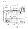
FIG. 6 is a partially omitted rear view showing the configuration of the cooking device according to a preferred embodiment; -
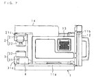
FIG. 7 is a partially omitted right-side view showing the configuration of the cooking device according to a preferred embodiment; - FTG. 8 is a partially omitted left-side view showing the configuration of the cooking device according to a preferred embodiment;
-
FIG. 9 is a schematic sectional view showing the configuration of the cooking device according to a preferred embodiment; -
FIG. 10A is a schematic front view showing a configuration of an electromagnetic generating unit, andFIG. 10B is a schematic side view thereof; -
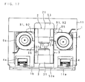
FIG. 11 is a schematic rear view showing a configuration for cooling a first electromagnetic generating unit and a second electromagnetic generating unit; -
FIG. 12 is a schematic right-side view showing the configuration for cooling the first and the second electromagnetic generating units; -
FIG. 13 is a schematic left-side view showing the configuration for cooling the first and the second electromagnetic generating units; -
FIG. 14 is a sectional view of line X-X ofFIG. 12 ; -
FIG. 15A is an exploded side view showing a relation among the first electromagnetic generating unit, an air regulating plate and an insulating plate,FIG. 15B is a side view with the air regulating plate in a mounted state, andFIG. 15C is a side view with the air regulating plate and the insulating plate in a mounted state; -
FIG. 16A is an exploded side view showing a relation among the second electromagnetic generating unit, the air regulating plate and the insulating plate,FIG. 16B is a side view with the air regulating plate in a mounted state, andFIG. 16C is a side view with the air regulating plate and the insulating plate in a mounted state; -
FIG. 17 is a schematic rear view of the cooking device according to a preferred embodiment; -
FIG. 18 is an explanatory view showing a relation between the first electromagnetic generating unit and an ventilation duct; and -
FIG. 19 is an explanatory view showing the relation between the first electromagnetic generating unit and the ventilation duct. - In the following, the present invention is detailed based upon drawings showing embodiments thereof.
FIG. 1 is a schematic perspective view showing a configuration of a cooking device according to the present invention;FIGS. 2 and3 are partially omitted rear-side perspective views each showing the configuration of the cooking device;FIG. 4 is a front view showing the configuration of the cooking device;FIG. 5 is a partially omitted plan view showing the configuration of the cooking device;FIG. 6 is a partially omitted rear view showing the configuration of the cooking device;FIG. 7 is a partially omitted right-side view showing the configuration of the cooking device;FIG. 8 is a partially omitted left-side view showing the configuration of the cooking device; andFIG. 9 is a schematic sectional view showing the configuration of the cooking device. - The cooking device shown in
FIG. 1 is a microwave oven that heats an object with electromagnetic waves. The cooking device has aheating chamber 1a on a front side for heating the object, and anelectric equipment chamber 1b behind theheating chamber 1a. The cooking device includes: acooking device body 1 that is formed in a substantial rectangular solid; a first and a secondelectromagnetic generating units electric equipment chamber 1b;transformers 4, 4a that drive the respectiveelectromagnetic generating units units electromagnetic generating units heating chamber 1a, respectively; and a first and asecond fans electromagnetic generating units - The
cooking device body 1 is formed in a substantially rectangular solid shape, and includes: acabinet 11 that has an open section at the front side of theheating chamber 1a; adoor 12 that opens and closes the forward open section; aenclosure 13 that is anteriorly arranged in thecabinet 11 and has theheating chamber 1a; anexhaust duct 14 that is arranged above (or on) theenclosure 13 and guides air inside theheating chamber 1a to an outside of thecabinet 11; anintake duct 15 that is arranged above (or on) theenclosure 13 and supplies the outside air to theheating chamber 1a; a third fan 16 for discharging the air inside theheating chamber 1a into theexhaust duct 14; a control unit that controls electric components such as theelectromagnetic generating units operating section 17 that operates the control unit; and the like. - The
cabinet 11 includes abase 11a that is formed in a rectangular shape; afront frame 11b that is connected to a front edge of thebase 11a and has the open section; arear frame 11c that is fixed at a rear edge of thebase 11a; and a coveringmember 11d that has both-side plates and a top plate and is formed in a substantial reversal U-shape. Theenclosure 13 is mounted on a front side of thebase 11a. Thedoor 12 is pivotably supported at one side of the open section of thefront frame 11b. - The
rear frame 11c includes grille-shaped first and second exhaust ports 1c, 1d that are vertically arranged an upper-center portion and a lower -center portion of therear frame 11c; a grille-shaped third discharge port 1e that is arranged on one side of the upper portion of therear frame 11c, and communicates to an outlet-side end of theexhaust duct 14; and a grille-shapedthird intake port 1f that is arranged on the other side of the upper portion of therear frame 11c, and communicates to an inlet-side end of anintake duct 15. Further, attached to therear frame 11c is anexhaust guide plate 11e that is arranged correspondingly to a position opposed to the exhaust ports 1c, 1d of therear frame 11c (cf.FIG. 3 ). - The covering
member 11d provides grille-shaped first andsecond exhaust ports 1g, 1h at front portions of the both lateral sides (cf.FIG. 5 ). - The
enclosure 13 is formed in a substantial rectangular solid having an open section at front side, and provides adischarge port 13a at one side of the top and asupply port 13b at the other side of the top. Theenclosure 13 provides a circular recess 13c at the center of the top and a circular recess 13d at the center of the bottom. The recesses 13c, 13d interiorly providerotational antennas motors 52, 52a that drive therotational antennas enclosure 13 includes cover plates 13e, 13f that are located at top and bottom of theheating chamber 1a and block openings of the circular recesss 13c, 13d. Furthermore, theenclosure 13 includes, at top of theheating chamber 1a,sensors rotational antennas shielding plate 13g for forming air course "a" between thisplate 13g and the top. - The
exhaust duct 14 and theintake duct 15 are formed in rectangular column shapes and have equal sizes, each other. At the bottom, theexhaust duct 14 provides an inlet that corresponds to thedischarge port 13a. At the bottom, theintake duct 15 provides an outlet that corresponds to thesupply port 13b. Further, theexhaust duct 14 interiorly provices a third fan 16. - As described above, in the
cooking device 1 that is formed in a substantial rectangular solid shape, the first electromagnetic supplyingunits 5 is positioned at the lateral center above (or on) theheating chamber 1a, while the second electromagnetic supplyingunits 5a is positioned at the lateral center below (or under) theheating chamber 1a. The firstelectromagnetic generating unit 2 is positioned behind theheating chamber 1a at the upper lateral center in thecooking device 1, while the secondelectromagnetic generating unit 3 is positioned behind theheating chamber 1a at the lower lateral center in thecooking device 1. The first andsecond fans electromagnetic generating unit 2, while thetransformers 4, 4a are positioned on the both sides of the secondelectromagnetic generating unit 3. - The first and second electromagnetic supplying
units rotational antennas motors 52, 52a that drive therotational antennas wave guide 53 has an open side that is opposed to the top of theheating chamber 1a, while thewave guide 53a has an open side that is opposed to the bottom of theheating chamber 1a. The longitudinal rear edges of the wave guides 53, 53a are behind theenclosure 13. The longitudinal front edges of the wave guides 53, 53a are around the anteroposterior center of theenclosure 13. Further, the wave guides 53, 53a serve as the above-mentioned recesses 13c, 13d. -
FIGS. 10A and 10B show configurations of theelectromagnetic generating units FIG. 10A is a schematic front view andFIG. 10B is a schematic side view. The first electromagnetic generating unit and the secondelectromagnetic generating unit electromagnetic generating sections sections electromagnetic generating sections - The
electromagnetic generating sections resonant sections fins resonant sections frame yokes resonant sections fins antennas 21d, 31d, each of which protrudes from one end of theresonant section frame yoke resonant section resonant sections sections power supply terminals power supply terminals - The frame yokes 21c, 31c are formed in rectangular hollow column shapes that are opened anteroposteriorly. The
resonant sections antennas 21d, 31d, in protruding conditions. Furthermore, the the frame yokes 21c, 31c providesecond partition plates sections second partition plates - The driving
sections sections sections power supply terminal power supply terminals connector 20a, with one end of thepower supply line 20 whose the other end is connected with thetransformer 4 or 4a. - In the
electromagnetic generating units sections electromagnetic generating section 21 is arranged on the drivingsection 22, while theelectromagnetic generating section 31 is, on the other hand, arranged under the drivingsection 32. Thepower supply terminals frame yoke 21c is attached to the top plate of a ventilation duct, which is described later. Theantenna 21d is arranged inside a rear portion of thewave guide 53. Further, the mounting piece of theframe yoke 31c is attached to the bottom plate of the ventilation duct, which is described later. The antenna 31d is arranged inside a rear portion of thewave guide 53a. Moreover, the frame yokes 21c, 31c are opened anteroposteriorly. - Therefore, the first and the second
electromagnetic generating units heating chamber 1a, are backwardly spaced from theheating chamber 1a. Further, on lateral peripheries of theelectromagnetic generating units ventilation duct 9 andpartition wall 10 serve to form a first blowing path and asecond blowing path 8, 8a which serve to blow almost equivalent amount of air for cooling to the respectiveelectromagnetic generating units -
FIGS. 11 to 16C show configurations for cooling the first and the secondelectromagnetic generating units FIG. 11 is a schematic rear view,FIG. 12 is a schematic right-side view,FIG. 13 is a schematic left-side view, andFIG. 14 is a sectional view of line X-X ofFIG. 12 .FIGS. 15A, 15B, 15C each show a relation among the first electromagnetic generating unit, an air regulating plate and an insulating plate, whereFIG. 15A is an exploded side view,FIG. 15B is a side view with the air regulating plate in a mounted state, andFIG. 15C is a side view with the air regulating plate and the insulating plate in a mounted state. Further,FIGS. 16A, 16B, 16C each show a relation among the second electromagnetic generating unit, the air regulating plate and the insulating plate, whereFIG. 16A is an exploded side view,FIG. 16B is a side view with the air regulating plate in a mounted state, andFIG. 16C is a side view with the air regulating plate and the insulating plate in a mounted state. Moreover,FIG. 17 is a schematic rear view of the cooking device. - The
ventilation duct 9 includes: twoair regulating plates electromagnetic generating units plates air regulating plates enclosure 13; therear frame 11c having the first and the second exhaust ports 1c, 1d; atop plate 93 fixed to an upper portion of the firstelectromagnetic generating section 21; and abottom plate 94 fixed to a lower portion of the secondelectromagnetic generating section 21. Thepartition wall 10 is arranged in theventilation duct 9 to divide the latter into top and bottom portions, for the driving-sections sections second blowing path 8, 8a. - The
air regulating plate 91 is a metal plate, and includes: a first and asecond plate sections electromagnetic generating sections section 91c that is continued from front portions of theplate sections air regulating plate 91 is formed in a substantial U-shape that is opened at the portion corresponding to lateral sides of the drivingsections first inlet port 95 is opened at a portion near one side of the connectingsection 91c of thefirst plate section 91a, while asecond inlet port 96 is opened at a portion near the other side of the connectingsection 91c. Thefirst inlet port 95 communicates to an outlet port for thefirst fan 6, while thesecond inlet port 96 communicates to an outlet port for thesecond fan 6a. - As shown in
FIG. 11 , there are lateral separations "b" between thesecond partition plate 10c protruding from theframe yoke 21c and an under edge (opening edge) of thefirst plate section 91a, and between thesecond partition plate 10c protruding from theframe yoke 21c and an upper edge (opening edge) of thesecond plate section 91b. The lateral separations "b" are laterally spaced apart, each other. - The insulating
plate 92 is a built-up mica that has an excellent processibility as well as heat resistance and voltage endurance. One insulatingplate 92 has aninsertion hole 92a that is backwardly recessed at the portion corresponding to thepower supply terminal 22a, while another insulatingplate 92 has aninsertion hole 92b that is backwardly recessed at the portion corresponding to thepower supply terminal 32a. An upper portion of the insulatingplate 92 is supported by insertion into a gap between thefirst plate section 91a and thesecond partition plate 10b, while a lower portion of the insulatingplate 92 is supported by insertion a gap between thesecond plate section 91b and thesecond partition plate 10b. Further, theinsertion holes connectors plate 92 is possible to be mounted without external tension and stress because of being softly supported by insertion, although the built-up mica is generally known to be difficult for fixing with screwing and caulking and to be unsuitable for mounting on a structure material like a duct wall because of mechanical fragility. - A clearance between the
insertion hole 92a and theconnector 20a and a clearance between theinsertion hole 92b and theconnector 20a are blocked by blockingmembers members plates connectors - The
top plate 93 is formed integrally with thefirst plate sections air regulating plates top plate 93 is fixed to an upper portion of theenclosure 13. Further, thetop plate 93 is attached to theframe yoke 21c, while having a penetrating hole at the center for insertion of theantenna 21d. - The
bottom plate 94 is formed integrally with thesecond plate sections air regulating plates top plate 93 is fixed to a lower portion of theenclosure 13. Further, thebottom plate 94 is attached to theframe yoke 31c, while having a penetrating hole at the center for insertion of the antenna 31d. - The
partition wall 10 consists of: afirst partition plate 10a that is extending in an up-and-down direction between theelectromagnetic generating sections second inlet port 96 and the drivingsections ventilation duct 9 into a front portion and a back portion; andsecond partition plates first partition plate 10a between the first andsecond inlet port ventilation duct 9 near theinlet port 95, 96 (front side) into upper portions and lower portions. Furhter, thepartition wall 10 serves to form thefirst blowing path 8 around the upper portion of theventilation duct 9 and the second blowing path 8a around the lower portion of theventilation duct 9. Thesecond partition plate 10b is connected to thefirst plate sections air regulating plates FIG. 14 . InFIG. 14 , one end of thesecond partition plate 10b near thefirst fan 6 is lower than the other end of thesecond partition plate 10b near thesecond fan 6a. Thesecond partition plates frame yoke 21c and at an upper portion of theframe yoke 31c. - The first and the
second blowing paths 8, 8a are set to blow substantial quivalent amount of air. Thefirst blowing path 8 is formed between thefirst inlet port 95 and the first exhaust port 1c, inside theframe yoke 21c, while between theair regulating plates frame yoke 21c. Further, thefirst blowing path 8 communicates to the first exhaust port 1c. The second blowing path 8a is formed between thesecond inlet port 96 and the second exhaust port 1d, as well as between thefirst partition plate 10a and the rear surface of theenclosure 13, inside theframe yoke 31c, and between theair regulating plates plates frame yoke 31c. Further, the second blowing path 8a communicates to the second exhaust port 1d. - The first and the
second fans enclosure 13, while the first andsecond inlet ports - In the cooking device as described above, manipulation of the
operating section 17 on the front surface allows the control unit to energize the drivingsections electromagnetic generating units heating chamber 1a. Theantennas 21d, 31d of theelectromagnetic generating sections heating chamber 1a by the wave guides 53, 53a and therotational antennas heating chamber 1a. During this procedure, the first tothird fans - Air in the
heating chamber 1a is sucked from thedischarge port 13a of theenclosure 13 into theexhaust duct 14 by the third fan 16. Then, an inner pressure of theheating chamber 1a is decreased to suck external air from thethird intake port 1f into theintake duct 15. The air sucked into theintake duct 15 is supplied to theheating chamber 1a through thesupply port 13b. Then, air in theheating chamber 1a is passed inside theexhaust duct 14 and discharged from the third discharge port 1e to the outside. - Further, external air is sucked into the covering
member 11d by the first and thesecond fans second exhaust ports 1g, 1h that are opened on the coveringmember 11d. The air blown out from the outlet port of thefirst fan 6 is guided to thefirst blowing path 8 through thefirst inlet port 95. Therefore, it is possible for the air guided to thefirst blowing path 8 to intensively cool the lateral periphery of theelectromagnetic generating section 21. Furthermore, the air blown out from the outlet port of thesecond fan 6a is guided to the second blowing path 8a through thesecond inlet port 96. Therefore, it is possible for the air guided to the second blowing path 8a to intensively cool the lateral periphery of theelectromagnetic generating section 31. - The air of the
first blowing path 8 is discharged to the outside from the first exhaust port 1c of therear frame 11c, while the air of the second blowing path 8a is discharged to the outside from the second exhaust port 1d of therear frame 11c. It is possible to equalize the amounts of air supplied from the first and thesecond blowing paths 8, 8a to the lateral peripheries of theelectromagnetic generating sections electromagnetic generating sections fans electromagnetic generating sections partition wall 10 blocks air flows to and from the drivingsections electromagnetic generating sections electromagnetic generating units electromagnetic generating sections - As described above, the cooking device provides the
ventilation duct 9, solid metal plates to support theelectromagnetic generating units plates electromagnetic generating units plates ventilation duct 9 are softly supported by insertion at the upper and the lower portions, and blocked off the clearance between theconnectors power supply lines power supply terminals insertion holes plates electromagnetic generating units ventilation duct 9 portion, because these configurations prevent wastage/damage of a screw head/thread and the like that are concerned for screw-fixed insulating plates. - Moreover, as shown in
FIG. 11 , the lower edge of thefirst plate section 91a is spaced vertical "b" apart from thesecond partition plate 10c, while the upper edge of thesecond plate section 91b is spaced vertical "b" apart from thesecond partition plate 10c. Therefore, it is possible to facilitate mounting/demount of the insulatingplates -
FIGS. 18 and19 are explanatory views that show relations between the firstelectromagnetic generating unit 2 and theventilation duct 9. As shown inFIG. 11 , the embodiment described above provides the vertical separations "b" and the lateral separations "c" between the lower edge of thefirst plate section 91a and thesecond partition plate 10c, and between the upper edge of thesecond plate section 91b and thesecond partition plate 10c. Therefore, even in a case where distances of the lateral separations "c" between thesecond partition plates air regulating plates plate 92 inside thefirst plate section 91a through a gap under the lower edge of thefirst plate section 91a by bending the insulatingplate 92 having plastic property that is arranged near the shorter separation "c" as shown inFIG. 18 . It is to be noted that, in a cooking device that provides thesecond partition plates air regulating plates first plate section 91a and thesecond partition plate 10c as shown inFIG. 19 , it is difficult to insert the insulatingplate 92 near the shorter separation "c" into a gap between thefirst plate section 91a and thesecond partition plate 10c. - In addition, although the embodiment described above is configured to have the two
fans second blowing paths 8, 8a, another embodiment may have one fan that supplies air to both the first and thesecond blowing paths 8, 8a. Further, although the embodiment described above is configured to have the first and thesecond blowing paths 8, 8a that supply air to the lateral peripheries of theelectromagnetic generating sections second blowing paths 8, 8a that supply air to the peripheries of theelectromagnetic generating sections sections - It should be understood that the embodiment described herein is only illustrative of the present invention and that various modifications may be made thereto without departing from the scope of the invention as defined in the appended claims.
Claims (9)
- A cooking device, comprising: a first electromagnetic generating unit (2) and a second electromagnetic generating unit (3) for generating electromagnetic waves to cook; a heating chamber (1a) for introducing the electromagnetic waves generated by the first (2) and the second (3) electromagnetic generating units, to heat an object; fans (6, 6a) for cooling the first (2) and the second (3) electromagnetic generating units, respectively; and a first blowing path and a second blowing path (8, 8a) for blowing respective air flown by the fans (6, 6a) around the first (2) and the second (3) electromagnetic generating units respectively, characterized in that:the first electromagnetic generating unit (2) is arranged in an upper position and the second electromagnetic generating unit (3) is arranged in a lower position, whereineach of the first (2) and the second (3) electromagnetic generating unit vertically comprises:an electromagnetic generating section (21, 31); anda driving section (22, 32) for driving the electromagnetic generating section (21, 31),the driving sections (22, 32) are opposed each other, in an up-and-down direction, andthe electromagnetic generating sections (21, 31) and the driving sections (22, 32) are vertically collinear.
- The cooking device according to claim 1, further comprising:a ventilation duct (9) for surrounding both lateral peripheries of the first (2) and the second (3) electromagnetic generating units; anda partition wall (10) for vertically dividing an inside of the ventilation duct (9) into a portion for the driving section (22, 32) and a portion for the electromagnetic generating section (21, 31) of each of the first (2) and the second (3) electromagnetic wave generating unit.
- The cooking device according to claim 2, wherein
the partition wall (10) comprises:a first partition plate (10a) that extends in an up-and-down direction on both lateral sides of the driving sections (22, 32) of both the first and the second electromagnetic generating units; andsecond partition plates (10b, 10c) that extend laterally from the first partition plate (10a). - The cooking device according to any one of claim 1 to 3, further comprising:insulating plates (92, 92) that are arranged on a lateral side of the driving sections (22, 32) of both the first and the second electromagnetic generating units, wherein the insulating plates have insertion holes.(92a, 92b); andpower supply lines that are connected to the driving sections (22, 23) of both the first and the second electromagnetic generating units, through the insertion holes (92a, 92b).
- The cooking device according to claim 4, wherein
the insulating plate (92) forms a part of the ventilation duct (9). - The cooking device according to claim 5, wherein
each of the driving section (22, 32) comprises a power supply terminal (22a, 32a) that is protruding laterally,
the ventilation duct (9) comprises:an air regulating plate (91) that is arranged on both lateral sides of the electromagnetic generating sections (21, 31) of both the first and the second electromagnetic generating units, wherein the air regulating plate (91) has an aperture area that is arranged correspondingly to an arrangement of the power supply terminals (22a, 32a),the insulating plate (92) is superimposed on the air regulating plate (91), andthe insertion hole (92a, 92b) is opened laterally on the basis of a position of the power supply terminal (22a, 32a). - The cooking device according to claim 6, wherein
the power supply line (20) comprises:a connector (20a) that is connected to the power supply terminal (22a, 32a) and arranged inside the insertion hole (92a, 92b), andthe insulating plate (92) is fixed to the connector (20a) by a blocking member (30) that blocks off a gap between the insertion hole (92a, 92b) and the connector (20a). - The cooking device according to claim 6 or 7, wherein
the insulating plate (92) is supported by insertion into a gap between the second partition plate (10b, 10c) and the air regulating plate (91). - The cooking device according to claim 8, wherein
the second partition plate (10b, 10c) is spaced apart vertically and laterally from an edge of the aperture area.
Applications Claiming Priority (1)
| Application Number | Priority Date | Filing Date | Title |
|---|---|---|---|
| JP2008035074A JP4637193B2 (en) | 2008-02-15 | 2008-02-15 | Cooker |
Publications (2)
| Publication Number | Publication Date |
|---|---|
| EP2091300A1 EP2091300A1 (en) | 2009-08-19 |
| EP2091300B1 true EP2091300B1 (en) | 2013-04-24 |
Family
ID=40637171
Family Applications (1)
| Application Number | Title | Priority Date | Filing Date |
|---|---|---|---|
| EP09250313.5A Active EP2091300B1 (en) | 2008-02-15 | 2009-02-06 | Cooking device |
Country Status (4)
| Country | Link |
|---|---|
| US (1) | US20090206076A1 (en) |
| EP (1) | EP2091300B1 (en) |
| JP (1) | JP4637193B2 (en) |
| CN (1) | CN101507579B (en) |
Families Citing this family (3)
| Publication number | Priority date | Publication date | Assignee | Title |
|---|---|---|---|---|
| KR101741745B1 (en) | 2010-11-25 | 2017-05-31 | 동부대우전자 주식회사 | Microwave oven |
| CN104869679B (en) * | 2015-06-09 | 2017-08-04 | 内蒙古科技大学 | A kind of apparatus and method for realizing variable frequency microwave heating |
| CN107467094A (en) * | 2017-09-22 | 2017-12-15 | 长齐胜餐饮管理(深圳)有限公司 | Microwave hot air combined roasting plant and burn cured baking method |
Family Cites Families (15)
| Publication number | Priority date | Publication date | Assignee | Title |
|---|---|---|---|---|
| US3654417A (en) * | 1970-10-30 | 1972-04-04 | Litton Precision Prod Inc | Microwave oven including air flow system |
| FR2191254B1 (en) * | 1972-06-30 | 1977-08-05 | Hitachi Ltd | |
| JPS58175725A (en) * | 1982-04-07 | 1983-10-15 | Matsushita Electric Ind Co Ltd | Microwave heater device |
| JPH0810630B2 (en) * | 1988-02-29 | 1996-01-31 | 松下電器産業株式会社 | High frequency heating equipment |
| JPH01225088A (en) * | 1988-03-03 | 1989-09-07 | Matsushita Electric Ind Co Ltd | High-frequency heating device |
| JPH04121991A (en) * | 1990-09-11 | 1992-04-22 | Matsushita Electric Ind Co Ltd | High frequency heating device |
| US5451751A (en) * | 1992-01-23 | 1995-09-19 | Kabushiki Kaisha Toshiba | High-frequency heating apparatus with wave guide switching means and selective power switching means for magnetron |
| JP2740411B2 (en) | 1992-05-25 | 1998-04-15 | 三洋電機株式会社 | microwave |
| JPH08203664A (en) * | 1995-01-26 | 1996-08-09 | Sanyo Electric Co Ltd | Microwave oven |
| GB2344501A (en) * | 1999-07-02 | 2000-06-07 | Merrychef Ltd | Antenna disposition in microwave heating apparatus |
| JP2001108243A (en) * | 1999-10-01 | 2001-04-20 | Sanyo Electric Co Ltd | Microwave oven |
| AU2001215121A1 (en) * | 2000-11-20 | 2002-05-27 | Jianhua Luo | Multifunction microwave device |
| JP3926118B2 (en) * | 2001-07-24 | 2007-06-06 | 株式会社東芝 | Cooker |
| JP2003074872A (en) * | 2001-09-05 | 2003-03-12 | Sanyo Electric Co Ltd | High frequency cooker |
| KR100436148B1 (en) * | 2001-12-24 | 2004-06-14 | 삼성전자주식회사 | Microwave oven |
-
2008
- 2008-02-15 JP JP2008035074A patent/JP4637193B2/en not_active Expired - Fee Related
-
2009
- 2009-02-06 EP EP09250313.5A patent/EP2091300B1/en active Active
- 2009-02-13 US US12/370,673 patent/US20090206076A1/en not_active Abandoned
- 2009-02-13 CN CN2009100072155A patent/CN101507579B/en not_active Expired - Fee Related
Also Published As
| Publication number | Publication date |
|---|---|
| JP2009192179A (en) | 2009-08-27 |
| JP4637193B2 (en) | 2011-02-23 |
| CN101507579B (en) | 2011-08-24 |
| US20090206076A1 (en) | 2009-08-20 |
| CN101507579A (en) | 2009-08-19 |
| EP2091300A1 (en) | 2009-08-19 |
Similar Documents
| Publication | Publication Date | Title |
|---|---|---|
| US8513579B2 (en) | Heater assembly for microwave oven and microwave oven having the same | |
| KR20080078760A (en) | Induction heating device | |
| KR20060128067A (en) | Oven | |
| EP2091300B1 (en) | Cooking device | |
| JP2002221324A (en) | Cooling device for electric accessory part for combination hood and microwave oven | |
| US4549054A (en) | Microwave oven construction having separate component receiving chambers | |
| US6852963B2 (en) | Wall-mounted type microwave oven | |
| US6660984B1 (en) | Wall-mounted type microwave oven | |
| KR101207306B1 (en) | convection heating unit and heating cooker having the same | |
| CN219165619U (en) | Radio frequency generating device, radio frequency thawing device and refrigerator | |
| US7692124B2 (en) | Air flow passage of microwave oven | |
| CN219390225U (en) | Power module assembly, radio frequency generating device, radio frequency thawing device and refrigerator | |
| CN219515187U (en) | Radio frequency generating device, radio frequency thawing device and refrigerator | |
| JP2011008933A (en) | Induction heating cooker | |
| KR101652999B1 (en) | Microwave oven having hood | |
| KR20040021150A (en) | Heater assembly for microwave oven | |
| KR100595261B1 (en) | convection type microwave oven | |
| KR20220165594A (en) | Electric range | |
| KR101012354B1 (en) | microwave oven | |
| KR20230103499A (en) | Microwave oven having hood | |
| KR102037380B1 (en) | A cooking apparatus | |
| CN112971551A (en) | Cooking device | |
| JP2001110559A (en) | High frequency heating apparatus | |
| KR19990018403U (en) | Microwave Multi Waveguide | |
| KR20000003595U (en) | Microwave |
Legal Events
| Date | Code | Title | Description |
|---|---|---|---|
| PUAI | Public reference made under article 153(3) epc to a published international application that has entered the european phase |
Free format text: ORIGINAL CODE: 0009012 |
|
| AK | Designated contracting states |
Kind code of ref document: A1 Designated state(s): AT BE BG CH CY CZ DE DK EE ES FI FR GB GR HR HU IE IS IT LI LT LU LV MC MK MT NL NO PL PT RO SE SI SK TR |
|
| AX | Request for extension of the european patent |
Extension state: AL BA RS |
|
| 17P | Request for examination filed |
Effective date: 20100212 |
|
| AKX | Designation fees paid |
Designated state(s): DE FR GB |
|
| GRAP | Despatch of communication of intention to grant a patent |
Free format text: ORIGINAL CODE: EPIDOSNIGR1 |
|
| GRAS | Grant fee paid |
Free format text: ORIGINAL CODE: EPIDOSNIGR3 |
|
| GRAA | (expected) grant |
Free format text: ORIGINAL CODE: 0009210 |
|
| AK | Designated contracting states |
Kind code of ref document: B1 Designated state(s): DE FR GB |
|
| REG | Reference to a national code |
Ref country code: GB Ref legal event code: FG4D |
|
| REG | Reference to a national code |
Ref country code: DE Ref legal event code: R096 Ref document number: 602009015175 Country of ref document: DE Effective date: 20130620 |
|
| PLBE | No opposition filed within time limit |
Free format text: ORIGINAL CODE: 0009261 |
|
| STAA | Information on the status of an ep patent application or granted ep patent |
Free format text: STATUS: NO OPPOSITION FILED WITHIN TIME LIMIT |
|
| 26N | No opposition filed |
Effective date: 20140127 |
|
| REG | Reference to a national code |
Ref country code: DE Ref legal event code: R097 Ref document number: 602009015175 Country of ref document: DE Effective date: 20140127 |
|
| REG | Reference to a national code |
Ref country code: DE Ref legal event code: R084 Ref document number: 602009015175 Country of ref document: DE |
|
| REG | Reference to a national code |
Ref country code: GB Ref legal event code: 746 Effective date: 20140918 |
|
| REG | Reference to a national code |
Ref country code: DE Ref legal event code: R084 Ref document number: 602009015175 Country of ref document: DE Effective date: 20141002 |
|
| REG | Reference to a national code |
Ref country code: FR Ref legal event code: PLFP Year of fee payment: 8 |
|
| REG | Reference to a national code |
Ref country code: FR Ref legal event code: PLFP Year of fee payment: 9 |
|
| REG | Reference to a national code |
Ref country code: FR Ref legal event code: PLFP Year of fee payment: 10 |
|
| PGFP | Annual fee paid to national office [announced via postgrant information from national office to epo] |
Ref country code: FR Payment date: 20210225 Year of fee payment: 13 |
|
| PGFP | Annual fee paid to national office [announced via postgrant information from national office to epo] |
Ref country code: DE Payment date: 20210217 Year of fee payment: 13 |
|
| REG | Reference to a national code |
Ref country code: DE Ref legal event code: R119 Ref document number: 602009015175 Country of ref document: DE |
|
| PG25 | Lapsed in a contracting state [announced via postgrant information from national office to epo] |
Ref country code: FR Free format text: LAPSE BECAUSE OF NON-PAYMENT OF DUE FEES Effective date: 20220228 |
|
| PG25 | Lapsed in a contracting state [announced via postgrant information from national office to epo] |
Ref country code: DE Free format text: LAPSE BECAUSE OF NON-PAYMENT OF DUE FEES Effective date: 20220901 |
|
| PGFP | Annual fee paid to national office [announced via postgrant information from national office to epo] |
Ref country code: GB Payment date: 20230221 Year of fee payment: 15 |