EP2091123A2 - An earthing arrangement for a DC electrical system and a method of operating an earthing arrangement for a DC electrical system - Google Patents
An earthing arrangement for a DC electrical system and a method of operating an earthing arrangement for a DC electrical system Download PDFInfo
- Publication number
- EP2091123A2 EP2091123A2 EP09250190A EP09250190A EP2091123A2 EP 2091123 A2 EP2091123 A2 EP 2091123A2 EP 09250190 A EP09250190 A EP 09250190A EP 09250190 A EP09250190 A EP 09250190A EP 2091123 A2 EP2091123 A2 EP 2091123A2
- Authority
- EP
- European Patent Office
- Prior art keywords
- earthing
- earth
- switch
- electrical system
- points
- Prior art date
- Legal status (The legal status is an assumption and is not a legal conclusion. Google has not performed a legal analysis and makes no representation as to the accuracy of the status listed.)
- Granted
Links
- 238000000034 method Methods 0.000 title claims description 20
- 239000007787 solid Substances 0.000 claims abstract description 44
- HBMJWWWQQXIZIP-UHFFFAOYSA-N silicon carbide Chemical compound [Si+]#[C-] HBMJWWWQQXIZIP-UHFFFAOYSA-N 0.000 claims description 8
- 229910010271 silicon carbide Inorganic materials 0.000 claims description 8
- 238000011965 cell line development Methods 0.000 description 4
- 230000002159 abnormal effect Effects 0.000 description 1
- 238000001514 detection method Methods 0.000 description 1
- 239000000446 fuel Substances 0.000 description 1
- 230000036039 immunity Effects 0.000 description 1
- 238000002955 isolation Methods 0.000 description 1
- XLYOFNOQVPJJNP-UHFFFAOYSA-N water Substances O XLYOFNOQVPJJNP-UHFFFAOYSA-N 0.000 description 1
Images


Classifications
-
- H—ELECTRICITY
- H02—GENERATION; CONVERSION OR DISTRIBUTION OF ELECTRIC POWER
- H02H—EMERGENCY PROTECTIVE CIRCUIT ARRANGEMENTS
- H02H9/00—Emergency protective circuit arrangements for limiting excess current or voltage without disconnection
- H02H9/08—Limitation or suppression of earth fault currents, e.g. Petersen coil
-
- H—ELECTRICITY
- H02—GENERATION; CONVERSION OR DISTRIBUTION OF ELECTRIC POWER
- H02H—EMERGENCY PROTECTIVE CIRCUIT ARRANGEMENTS
- H02H7/00—Emergency protective circuit arrangements specially adapted for specific types of electric machines or apparatus or for sectionalised protection of cable or line systems, and effecting automatic switching in the event of an undesired change from normal working conditions
- H02H7/26—Sectionalised protection of cable or line systems, e.g. for disconnecting a section on which a short-circuit, earth fault, or arc discharge has occured
- H02H7/268—Sectionalised protection of cable or line systems, e.g. for disconnecting a section on which a short-circuit, earth fault, or arc discharge has occured for dc systems
Definitions
- the present invention relates to an earthing arrangement for a DC electrical system and a method of operating an earthing arrangement for a DC electrical system.
- Earthing is one of the key design factors in all electrical systems, or electrical networks. Earthing has an influence on both the security and the reliability of an electrical system under fault conditions and the quality of supply under normal conditions.
- Grounding is defined by the IEEE as "a conducting connection, whether intentional or unintentional, by which an electric current or equipment is connected to earth or some conducting body of relatively large extent that serves in place of earth".
- Earthing methods for electrical systems/electrical networks have been established for many years, the common methods are classified as ungrounded, solidly grounded, high impedance grounded, low impedance grounded and resonant grounded.
- grounding method is influenced by the specific application and is a compromise between factors such as cost, ease of fault detection, personnel safety, fault induced over-voltages and over currents, consistency of power supply, stress on components etc.
- electrical connection(s) from an electrical system to ground are at specified selected locations to achieve the optimum desired performance of the electrical system under normal conditions and abnormal, fault, conditions.
- the present invention seeks to provide a novel earthing arrangement for a DC electrical system which reduces, preferably overcomes, the above mentioned problem.
- the present invention provides an earthing arrangement for a DC electrical system, the electrical system comprising a plurality of earthing points, a plurality of high impedance connections to earth, a plurality of solid connections to earth and a plurality of switches, each switch is arranged to connect a respective one of the earthing points to earth by a respective one of the high impedance connections or to connect the respective one of the earthing points to earth by a respective one of the solid connections.
- Each earthing point may be directly and permanently connected to earth by a high impedance connection and each earthing point is selectively connectable to earth in electrical parallel with the high impedance connection by a solid connection and a switch and wherein the switch between the earthing point and the earth of only one of the plurality of earthing points is closed.
- each source of electrical energy is removably connected to the electrical system by a respective pair of second switches, each source of energy has an earthing arrangement, each earthing arrangement having a earthing point.
- the earthing point is from a load or from a cable of the electrical system.
- the electrical system comprises a split +/-DC supply or a single 0/+ DC supply.
- the earthing point is positioned between a first capacitance and a second capacitance.
- the switch is a mechanical switch or an electrical switch.
- a current limiting diode provides the high impedance connection between the earthing point and earth, the current limiting diode provides the solid connection between the earthing point and earth and the current limiting diode provides the switch.
- the current limiting diode is a silicon carbide current limiting diode.
- the present invention also provides a method of operating an earthing arrangement for a DC electrical system, the electrical system comprising a plurality of earthing points, a plurality of high impedance connections to earth, a plurality of solid connections to earth and a plurality of switches, wherein in a first mode of operation at least one of the switches is arranged to connect a respective one of the earthing points to earth by a respective one of the solid connections and in a second mode of operation said at least one of the switches is arranged to connect the respective one of the earthing points to earth by the respective one of the high impedance connections.
- each of the switches may be arranged to connect a respective one of the earthing points to earth by a respective one of the solid connections and in a second mode of operation at least one of the switches is arranged to connect the respective one of the earthing points to earth by the respective one of the high impedance connections
- each earthing point is directly and permanently connected to earth by a high impedance connection and each earthing point is selectively connectable to earth in electrical parallel with the high impedance connection by a solid connection and a switch, wherein in a first mode of operation, the method comprises closing the switch between the earthing point and the earth of a first one of the plurality of earthing points and opening the switches between the earthing point and the earth of the remainder of the plurality of earthing points.
- the method may comprise opening the switch between the first one of the plurality of earthing points and maintaining the switches between the earthing point and the earth of the remainder of the plurality of earthing points in an open condition.
- the method may comprise isolating the first one of the plurality of earthing points from the electrical system and closing the switch between the earthing point and the earth of a second one of the plurality of earthing points and opening the switches between the earthing point and the earth of the remainder of the plurality of earthing points.
- the switch may b a mechanical switch or an electrical switch.
- a current limiting diode may provide the high impedance connection between the earthing point and earth, the current limiting diode provides the solid connection between the earthing point and earth and the current limiting diode provides the switch.
- the current limiting diode may be a silicon carbide current limiting diode.
- Each earthing point 24A, 24B, 24C is connected to the respective pair of cables 21A, 21B, 21C by a respective pair of capacitances 23A, 23B, 23C.
- each earthing point 24A, 24B, 24C is positioned between a first capacitance and a second capacitance, such that there is effectively a split +/- DC supply.
- the present invention provides a reconfigurable earthing arrangement in which each source of energy is connected to earth through an earthing point and the earthing points are always connected to earth via a high impedance connection and earthing points are also connected to earth via a solid connection and switch but at any particular time only one of the switches is closed and only one of the earthing points is connected to earth via the solid connection and the remainder of the switches are open.
- the switches 32A, 32B, 32C are fast acting switches.
- a single solid connection 30A to earth 26 is desirable under normal, un-faulted, operating conditions to alleviate noise in the DC electrical system 10.
- a high impedance connection 28A, 28B, 28C to earth 26 is desirable at the instant a fault occurs in the DC electrical system 10 to limit the current and hence the energy being released.
- the high impedance connections to earth at each source of energy enables the release of energy to be slowed in the event of fault condition and act as a back up connection to earth should the switch, or control for the switch, to connect the solid connection fail to operate.
- switch 32A In operation of the DC electrical system 10, switch 32A only is closed and thereby provides a solid connection 30A to earth 26 from the source of energy 12A and the remaining switches 32B, 32C are open. In the event of a rail to earth fault occurring anywhere in the DC electrical system 10, switch 32A is opened immediately by the controller 34 such that the high impedance connection 28A is provided in the fault path between the source of energy 12A and earth 26. The remaining switches 32B, 32C remain open. Once the fault is isolated, the switch 32 is closed again, by the controller 34, to reinstate the solid connection 30A to earth 26.
- either switch 32B or switch 32C is closed, by the controller 34, simultaneously with the isolation of the source of energy 12A, by the controller 34, such that a solid connection 30B or 30C is provided from the source of energy 12B or 12C for the electrical network 14.
- the advantages of the present invention are that the solid connection to earth reduces noise in the DC electrical system.
- the DC electrical system has the ability to limit energy release in the event of a positive rail to earth fault and/or a negative rail to earth fault.
- the DC electrical system has the ability to maintain a solid connection to earth as required, regardless of the number of sources of energy.
- the DC electrical system has the ability to reconfigure itself to maintain a solid connection to earth.
- the DC electrical system has the ability to maintain power continuity during a fault due to the presence of the high impedance connections.
- the DC electrical system has the ability to maintain safe operation in the event the controller, which controls the switches, to reconfigure the solid connections to earth fails to operate.
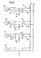
- FIG. 2 A further embodiment of the present invention is shown in figure 2 , and the embodiment in figure 2 is similar to that in figure 1 and like parts are denoted by like numbers.
- a 0/+ DC electrical system is shown in figure 2 .
- current limiting diodes 40A, 40B, 40C, CLDs for example silicon carbide current limiting diodes, SiC CLDs, are arranged between the earthing points 24A, 24B, 24C and earth 26 instead of the high impedance connector and the switch and solid connector.
- the earthing points 24A, 24B, 24C are provided on one of the pairs of electrical cables 21A, 21B, 21C.
- a current limiting diode 40 is effectively a resistance which dynamically changes, increases, with changing, increasing, current.
- the current limiting diode acts as a high impedance connector during fault conditions and a solid connection during normal conditions.
- a high current flow through the current limiting diodes 40A, 40B, 40C to earth 26 is instantaneously limited and therefore the current limiting diodes 40A, 40B, 40C behave as high impedance connections to earth 26.
- the current limiting diodes 40A, 40B, 40C returns to its zero resistance state once the fault is cleared. It may be that only one, or two, etc of the diodes 40A, 40B or 40C behaves as a high impedance connection to earth while the others remain as solid connections to earth.
- a further embodiment of the present invention is shown in figure 3 , and the embodiment in figure 3 is substantially the same as that in figure 1 and like parts are denoted by like numbers.
- pairs of current limiting diodes 40A, 42A, 40B, 42B, 40C, 42C CLDs for example silicon carbide current limiting diodes, SiC CLDs, are arranged between the earthing points 24A, 24B, 24C and earth 26 instead of the high impedance connector and the switch and solid connector.
- a current limiting diode 40 is effectively a resistance which dynamically changes, increases, with changing, increasing, current. In this arrangement the current limiting diode acts as a high impedance connector during fault conditions and a solid connection during normal conditions.
- the current limiting diodes 40A, 42A, 40B, 42B, 40C, 42C of each pair are arranged to limit the current flow in opposite directions.
- the fault path is through one of the current limiting diodes 40A, 40B, 40C, which will limit the current
- the current limiting diodes in each pair of current limiting diodes 40A, 42A, 40B, 42B, 40C, 42C are arranged in series. It may be that the diodes of only one, or two, etc of the pairs of diodes 40A, 42A, 40B, 42B, 40C or 42C behaves as a high impedance connection to earth while the others remain as solid connections to earth.
- each current limiting diodes act as, at provides, the high impedance connection between the earthing point and earth
- each current limiting diode acts as, or provides, the solid connection between the earthing point and earth
- each current limiting diode acts as, or provides the switch.
Abstract
Description
- The present invention relates to an earthing arrangement for a DC electrical system and a method of operating an earthing arrangement for a DC electrical system.
- Earthing, often referred to as grounding, is one of the key design factors in all electrical systems, or electrical networks. Earthing has an influence on both the security and the reliability of an electrical system under fault conditions and the quality of supply under normal conditions.
- Grounding is defined by the IEEE as "a conducting connection, whether intentional or unintentional, by which an electric current or equipment is connected to earth or some conducting body of relatively large extent that serves in place of earth".
- Earthing methods for electrical systems/electrical networks have been established for many years, the common methods are classified as ungrounded, solidly grounded, high impedance grounded, low impedance grounded and resonant grounded.
- The selection of grounding method is influenced by the specific application and is a compromise between factors such as cost, ease of fault detection, personnel safety, fault induced over-voltages and over currents, consistency of power supply, stress on components etc. Typically the electrical connection(s) from an electrical system to ground are at specified selected locations to achieve the optimum desired performance of the electrical system under normal conditions and abnormal, fault, conditions.
- Traditional electrical systems employ a fixed architecture and therefore the consistency of the connections to earth is easily maintained within the electrical system or electrical network.
- However, there is a requirement for more flexible electrical systems, or electrical networks, which have re-configurable architecture as a means of optimising the electrical supply and maintaining the reliability of the electrical supply. The reconfigurable electrical systems are able to re-configure their architecture as a means of optimising the power flow during normal operating conditions and maintaining the reliability of the power supply during faulted and/or over-loaded conditions. These re-configurable electrical systems must maintain a connection to earth throughout operation. Re-configurable electrical systems may inadvertently remove connections to earth from a main electrical system, or main electrical network, if a portion of the electrical system becomes isolated from the main electrical system. If a portion of the electrical system is switched out of the main electrical system, for example to remove a faulted portion of the electrical system, it is inevitable that the connection to earth could become isolated from the main electrical system leaving the main electrical system, or main electrical network, without a suitable earthing arrangement.
- Therefore, there is a need for a more advanced earthing arrangement which ensures that as portions of an electrical system are switched in and out of the main electrical system the optimum connection of the electrical system to earth is maintained.
- Accordingly the present invention seeks to provide a novel earthing arrangement for a DC electrical system which reduces, preferably overcomes, the above mentioned problem.
- Accordingly the present invention provides an earthing arrangement for a DC electrical system, the electrical system comprising a plurality of earthing points, a plurality of high impedance connections to earth, a plurality of solid connections to earth and a plurality of switches, each switch is arranged to connect a respective one of the earthing points to earth by a respective one of the high impedance connections or to connect the respective one of the earthing points to earth by a respective one of the solid connections.
- Each earthing point may be directly and permanently connected to earth by a high impedance connection and each earthing point is selectively connectable to earth in electrical parallel with the high impedance connection by a solid connection and a switch and wherein the switch between the earthing point and the earth of only one of the plurality of earthing points is closed.
- Preferably a plurality of sources of electrical energy are provided, each source of electrical energy is removably connected to the electrical system by a respective pair of second switches, each source of energy has an earthing arrangement, each earthing arrangement having a earthing point.
- Preferably the earthing point is from a load or from a cable of the electrical system.
- Preferably the electrical system comprises a split +/-DC supply or a single 0/+ DC supply.
- Preferably the earthing point is positioned between a first capacitance and a second capacitance.
- Preferably the switch is a mechanical switch or an electrical switch.
- Preferably a current limiting diode provides the high impedance connection between the earthing point and earth, the current limiting diode provides the solid connection between the earthing point and earth and the current limiting diode provides the switch.
- Preferably the current limiting diode is a silicon carbide current limiting diode.
- The present invention also provides a method of operating an earthing arrangement for a DC electrical system, the electrical system comprising a plurality of earthing points, a plurality of high impedance connections to earth, a plurality of solid connections to earth and a plurality of switches, wherein in a first mode of operation at least one of the switches is arranged to connect a respective one of the earthing points to earth by a respective one of the solid connections and in a second mode of operation said at least one of the switches is arranged to connect the respective one of the earthing points to earth by the respective one of the high impedance connections.
- In a first mode of operation each of the switches may be arranged to connect a respective one of the earthing points to earth by a respective one of the solid connections and in a second mode of operation at least one of the switches is arranged to connect the respective one of the earthing points to earth by the respective one of the high impedance connections
- Alternatively each earthing point is directly and permanently connected to earth by a high impedance connection and each earthing point is selectively connectable to earth in electrical parallel with the high impedance connection by a solid connection and a switch, wherein in a first mode of operation, the method comprises closing the switch between the earthing point and the earth of a first one of the plurality of earthing points and opening the switches between the earthing point and the earth of the remainder of the plurality of earthing points.
- In a second mode of operation, the method may comprise opening the switch between the first one of the plurality of earthing points and maintaining the switches between the earthing point and the earth of the remainder of the plurality of earthing points in an open condition.
- In a third mode of operation, the method may comprise isolating the first one of the plurality of earthing points from the electrical system and closing the switch between the earthing point and the earth of a second one of the plurality of earthing points and opening the switches between the earthing point and the earth of the remainder of the plurality of earthing points.
- The switch may b a mechanical switch or an electrical switch.
- A current limiting diode may provide the high impedance connection between the earthing point and earth, the current limiting diode provides the solid connection between the earthing point and earth and the current limiting diode provides the switch.
- The current limiting diode may be a silicon carbide current limiting diode.
- The present invention will be more fully described by way of example with reference to the accompanying drawing in which:-
-
Figure 1 shows an earthing arrangement for a DC electrical system according to the present invention. -
Figure 2 shows a further earthing arrangement for a DC electrical system according to the present invention. -
Figure 3 shows another earthing arrangement for a DC electrical system according to the present invention. - An earthing arrangement for a DC
electrical system 10 is shown infigure 1 . The DCelectrical system 10 comprises a plurality of sources ofelectrical energy electrical network 14 havingelectrical cables electrical energy electrical energy electrical network 14 of theelectrical system 10 by a respective pair ofswitches electrical cables switches electrical energy electrical cables - Each source of
energy earthing arrangement earthing arrangement earthing point earthing point earth 26 by ahigh impedance connection earthing point earth 26 in electrical parallel with the respectivehigh impedance connection solid connection switch switch 32A between theearthing point 24A and theearth 26 of only one of the plurality of sources ofenergy 12A is closed and theswitches earthing points earth 26 of all the other sources ofenergy earthing point 24A is directly connected toearth 26 by asolid connection 30A. Acontroller 34 is connected to each of theswitches switches - Each
earthing point cables capacitances earthing point - Thus, the present invention provides a reconfigurable earthing arrangement in which each source of energy is connected to earth through an earthing point and the earthing points are always connected to earth via a high impedance connection and earthing points are also connected to earth via a solid connection and switch but at any particular time only one of the switches is closed and only one of the earthing points is connected to earth via the solid connection and the remainder of the switches are open. The
switches - A single
solid connection 30A toearth 26 is desirable under normal, un-faulted, operating conditions to alleviate noise in the DCelectrical system 10. However, ahigh impedance connection earth 26 is desirable at the instant a fault occurs in the DCelectrical system 10 to limit the current and hence the energy being released. - The high impedance connections to earth at each source of energy enables the release of energy to be slowed in the event of fault condition and act as a back up connection to earth should the switch, or control for the switch, to connect the solid connection fail to operate.
- In operation of the DC
electrical system 10,switch 32A only is closed and thereby provides asolid connection 30A toearth 26 from the source ofenergy 12A and theremaining switches electrical system 10,switch 32A is opened immediately by thecontroller 34 such that thehigh impedance connection 28A is provided in the fault path between the source ofenergy 12A andearth 26. Theremaining switches controller 34, to reinstate thesolid connection 30A toearth 26. - In operation if the source of
energy 12A becomes isolated from theelectrical network 14 at any time, for example during re-configuration following a fault occurring in the feeders to source ofenergy 12A, either switch 32B orswitch 32C is closed, by thecontroller 34, simultaneously with the isolation of the source ofenergy 12A, by thecontroller 34, such that asolid connection energy electrical network 14. - If for some reason an appropriate one of the
switches controller 34, the integrity of the DCelectrical system 10 is maintained due to the presence of thehigh impedance connections earth 26, although the noise immunity is degraded due to the lack of a solid connection toearth 26. These back-uphigh impedance connections electrical system 10. - Although the present invention has been described with reference to positioning the earthing points between a pair of capacitances to provide a split +/- DC supply it is equally possible to provide the earthing point for a 0/+ DC supply.
- Although the present invention has been described with reference to providing earthing points and associated solid connections, switches and high impedance connections to earth from sources of energy it is equally possible to provide the earthing points and associated solid connections, switches and high impedance connections to earth from any part of the DC electrical system, including from loads or from the cables of the electrical network, whether a split +/- DC supply or a single 0/+ DC supply.
- The advantages of the present invention are that the solid connection to earth reduces noise in the DC electrical system. The DC electrical system has the ability to limit energy release in the event of a positive rail to earth fault and/or a negative rail to earth fault. The DC electrical system has the ability to maintain a solid connection to earth as required, regardless of the number of sources of energy. The DC electrical system has the ability to reconfigure itself to maintain a solid connection to earth. The DC electrical system has the ability to maintain power continuity during a fault due to the presence of the high impedance connections. The DC electrical system has the ability to maintain safe operation in the event the controller, which controls the switches, to reconfigure the solid connections to earth fails to operate.
- It may be possible to provide mechanical switches or electrical switches in the present invention.
- A further embodiment of the present invention is shown in
figure 2 , and the embodiment infigure 2 is similar to that infigure 1 and like parts are denoted by like numbers. Infigure 2 a 0/+ DC electrical system is shown. Infigure 2 current limitingdiodes points earth 26 instead of the high impedance connector and the switch and solid connector. The earthing points 24A, 24B, 24C are provided on one of the pairs ofelectrical cables diodes earth 26 and therefore the current limitingdiodes earth 26. In a fault condition a high current flow through the current limitingdiodes earth 26 is instantaneously limited and therefore the current limitingdiodes earth 26. The current limitingdiodes diodes - A further embodiment of the present invention is shown in
figure 3 , and the embodiment infigure 3 is substantially the same as that infigure 1 and like parts are denoted by like numbers. Infigure 3 pairs of current limitingdiodes points earth 26 instead of the high impedance connector and the switch and solid connector. A current limiting diode 40 is effectively a resistance which dynamically changes, increases, with changing, increasing, current. In this arrangement the current limiting diode acts as a high impedance connector during fault conditions and a solid connection during normal conditions. In an un-faulted condition no current flows through the current limitingdiodes earth 26 and therefore the current limitingdiodes earth 26. In a fault condition a high current flow through the current limitingdiodes earth 26 is instantaneously limited and therefore the current limitingdiodes earth 26. The current limitingdiodes diodes diodes diodes diodes diodes - Thus it is clear in
Figures 2 and3 that each current limiting diodes act as, at provides, the high impedance connection between the earthing point and earth, each current limiting diode acts as, or provides, the solid connection between the earthing point and earth and each current limiting diode acts as, or provides the switch.
Claims (17)
- An earthing arrangement for a DC electrical system (10), the electrical system (10) comprising a plurality of earthing points (24A, 24B, 24C), a plurality of high impedance connections (28A, 28B, 28C) to earth (26), a plurality of solid connections (30A, 30B, 30C) to earth (26) and a plurality of switches (32A, 32B, 32C), each switch (32A, 32B, 32C) is arranged to connect a respective one of the earthing points (24A, 24B, 24C) to earth (26) by a respective one of the high impedance connections (28A, 28B, 28C) or to connect the respective one of the earthing points (24A, 24B, 24C) to earth (26) by a respective one of the solid connections (30A, 30B, 30C).
- An earthing arrangement as claimed in claim 1 wherein each earthing point (24A, 24B, 24C) is directly and permanently connected to earth (26) by a high impedance connection (28A, 28B, 28C) and each earthing point (24A, 24B, 24C) is selectively connectable to earth (26) in electrical parallel with the high impedance connection (28A, 28B, 28C) by a solid connection (30A, 30B, 30C) and a switch (32A, 32B, 32C) and wherein the switch (32A, 32B, 32C) between the earthing point (24A, 24B, 24C) and the earth (26) of only one of the plurality of earthing points (24A, 24B, 24C) is closed.
- An earthing arrangement as claimed in claim 1 or claim 2 comprising a plurality of sources of electrical energy (12A, 12B, 12C), each source of electrical energy (12A, 12B, 12C) is removably connected to the electrical system (10) by a respective pair of second switches (20A, 20B, 20C), each source of electrical energy (12A, 12B, 12C) has an earthing arrangement (22A, 22B, 22C), each earthing arrangement (22A, 22B, 22C) having an earthing point.
- An earthing arrangement as claimed in claim 1 or claim 2 wherein the earthing point is from a load or from a cable of the electrical system.
- An earthing arrangement as claimed in any of claims 1 to 4 wherein the electrical system (10) comprises a split +/- DC supply or a single 0/+ DC supply.
- An earthing arrangement as claimed in claim 3 wherein the earthing point (24A, 24B, 24C) is positioned between a first capacitance and a second capacitance.
- An earthing arrangement as claimed in claim 2 wherein the switch (32A, 32B, 32C) is a mechanical switch or an electrical switch.
- An earthing arrangement as claimed in claim 1 wherein a current limiting diode (40A, 40B, 40C) provides the high impedance connection between the earthing point (24A, 24B, 23C) and earth (26), the current limiting diode (40A, 40B, 40C) provides the solid connection between the earthing point (24A, 24B, 24C) and earth (26) and the current limiting diode (40A, 40B, 40C) provides the switch.
- An earthing arrangement as claimed in claim 8 wherein the current limiting diode (40A, 40B, 40C) is a silicon carbide current limiting diode.
- A method of operating an earthing arrangement for a DC electrical system (10), the electrical system (10) comprising a plurality of earthing points (24A, 24B, 24C), a plurality of high impedance connections (28A, 28B, 28C) to earth (26), a plurality of solid connections (30A, 30B, 30C) to earth (26) and a plurality of switches (32A, 32B, 32C), wherein in a first mode of operation at least one of the switches (32A, 32B, 32C) is arranged to connect a respective one of the earthing points (24A, 24B, 24C) to earth (26) by a respective one of the solid connections (30A, 30B, 30C) and in a second mode of operation said at least one of the switches (32A, 32B, 32C) is arranged to connect the respective one of the earthing points (24A, 24B, 24C) to earth (26) by the respective one of the high impedance connections (28A, 28B, 28C).
- A method as claimed in claim 10 wherein in a first mode of operation each of the switches (32A, 32B, 32C) is arranged to connect a respective one of the earthing points (24A, 24B, 24C) to earth (26) by a respective one of the solid connections (30A, 30B, 30C) and in a second mode of operation at least one of the switches (32A, 32B, 32C) is arranged to connect the respective one of the earthing points (24A, 24B, 24C) to earth (26) by the respective one of the high impedance connections (28A, 28B, 28C).
- A method as claimed in claim 10 wherein each earthing point (24A, 24B, 24C) is directly and permanently connected to earth (26) by a high impedance connection (28A, 28B, 28C) and each earthing point (24A, 24B, 24C) is selectively connectable to earth (26) in electrical parallel with the high impedance connection (28A, 28B, 28C) by a solid connection (30A, 30B, 30C) and a switch (32A, 32B, 32C) wherein in a first mode of operation, the method comprises closing the switch (32A, 32B, 32C) between the earthing point (24A, 24B, 24C) and the earth (26) of a first one of the plurality of earthing points (24A, 24B, 24C) and opening the switches (32A, 32B, 32C) between the earthing point (24A, 24B, 24C) and the earth (26) of the remainder of the plurality of earthing points (24A, 24B, 24C).
- A method as claimed claim 12 wherein in a second mode of operation, the method comprises opening the switch (32A, 32B, 32C) between the first one of the plurality of earthing points (24A, 24B, 24C) and maintaining the switches (32A, 32B, 32C) between the earthing point (24A, 24B, 24C) and the earth (26) of the remainder of the plurality of earthing points (24A, 24B, 24C) in an open condition.
- A method as claimed in claim 12 or claim 13 wherein in a third mode of operation, the method comprises isolating the first one of the plurality of earthing points (24A, 24B, 24C) from the electrical system (10) and closing the switch (32A, 32B, 32C) between the earthing point (24A, 24B, 24C) and the earth (26) of a second one of the plurality of earthing points (24A, 24B, 24C) and opening the switches (32A, 32B, 32C) between the earthing point (24A, 24B, 24C) and the earth (26) of the remainder of the plurality of earthing points (24A, 24B, 24C).
- A method as claimed in claim 12, claim 13 or claim 14 wherein the switch (32A, 32B, 32C) is a mechanical switch or an electrical switch.
- A method as claimed in claim 11 wherein a current limiting diode (40A, 40B, 40C) provides the high impedance connection between the earthing point (24A, 24B, 24C) and earth (26), the current limiting diode (40A, 40B, 40C) provides the solid connection between the earthing point (24A, 24B, 24C) and earth (26) and the current limiting diode (40A, 40B, 40C) provides the switch (32A, 32B, 32C).
- A method as claimed in claim 16 wherein the current limiting diode (40A, 40B, 40C) is a silicon carbide current limiting diode.
Applications Claiming Priority (1)
| Application Number | Priority Date | Filing Date | Title |
|---|---|---|---|
| GBGB0802549.6A GB0802549D0 (en) | 2008-02-12 | 2008-02-12 | An earthing arrangement for a DC electrical system and a method of operating an earthing arrangement for a DC electrical system |
Publications (3)
| Publication Number | Publication Date |
|---|---|
| EP2091123A2 true EP2091123A2 (en) | 2009-08-19 |
| EP2091123A3 EP2091123A3 (en) | 2017-07-05 |
| EP2091123B1 EP2091123B1 (en) | 2020-04-22 |
Family
ID=39247494
Family Applications (1)
| Application Number | Title | Priority Date | Filing Date |
|---|---|---|---|
| EP09250190.7A Active EP2091123B1 (en) | 2008-02-12 | 2009-01-24 | An earthing arrangement for a DC electrical system and a method of operating an earthing arrangement for a DC electrical system |
Country Status (3)
| Country | Link |
|---|---|
| US (1) | US8111496B2 (en) |
| EP (1) | EP2091123B1 (en) |
| GB (1) | GB0802549D0 (en) |
Cited By (6)
| Publication number | Priority date | Publication date | Assignee | Title |
|---|---|---|---|---|
| DE102011055371A1 (en) | 2011-11-15 | 2013-05-16 | Sma Solar Technology Ag | Power limited generator earthing |
| WO2016008978A1 (en) * | 2014-07-16 | 2016-01-21 | Eaton Industries (Austria) Gmbh | Device to reduce residual current |
| EP3101748A1 (en) * | 2015-06-05 | 2016-12-07 | General Electric Company | Direct current power distribution and protection system |
| US10374412B2 (en) | 2015-10-12 | 2019-08-06 | Abb Schweiz Ag | Method and arrangement for facilitating clearing of a pole fault and isolation of a faulted pole in a power transmission system |
| EP3635851B1 (en) * | 2017-07-28 | 2022-03-30 | Siemens Energy Global GmbH & Co. KG | Current converter unit |
| GB2624151A (en) * | 2022-11-02 | 2024-05-15 | Rolls Royce Plc | Electrical power system |
Families Citing this family (2)
| Publication number | Priority date | Publication date | Assignee | Title |
|---|---|---|---|---|
| GB0814620D0 (en) * | 2008-08-12 | 2008-09-17 | Rolls Royce Plc | An electromechanical arrangement |
| CN103647504B (en) * | 2013-12-17 | 2015-09-23 | 刘继茂 | Solar cell earthing device and method |
Family Cites Families (10)
| Publication number | Priority date | Publication date | Assignee | Title |
|---|---|---|---|---|
| SE445002B (en) * | 1979-12-28 | 1986-05-20 | Asea Ab | POWER TRANSMISSION FOR HIGH-VOLTED DC WITH VOLTAGE LIMIT ORGAN TO LIMIT LINE VOLTAGE |
| DE4419945C2 (en) * | 1994-06-08 | 2001-01-25 | Hans Ludwig Schuck | Protective device to prevent the consequences of earth faults in high-voltage three-phase networks |
| US5666255A (en) * | 1995-06-05 | 1997-09-09 | Powervar, Inc. | Transformerless conditioning of a power distribution system |
| US6166458A (en) * | 1998-01-20 | 2000-12-26 | Leveler | Power conditioning circuit |
| SE520838C2 (en) * | 1999-05-19 | 2003-09-02 | Abb Ab | Electric power transmission system provided with disconnectors consisting of antiparallel coupled controllable power semiconductor elements |
| US20080089103A1 (en) * | 2005-06-13 | 2008-04-17 | Cheng-Chia Hsu | High efficiency dc to ac power converter |
| GB2436648A (en) | 2006-03-28 | 2007-10-03 | Rolls Royce Plc | Superconducting earth connection |
| US8213202B2 (en) * | 2006-05-24 | 2012-07-03 | John Akerlund | Energy distributing circuit arrangement, including a DC/DC-converter |
| US7339776B1 (en) * | 2006-12-12 | 2008-03-04 | Pratt & Whitney Rocketdyne, Inc. | Silicon carbide diode voltage limiter |
| US7646160B2 (en) * | 2007-04-26 | 2010-01-12 | Ford Global Technologies, Llc | Sensor calibration and parameter identification in a multi-phase motor drive |
-
2008
- 2008-02-12 GB GBGB0802549.6A patent/GB0802549D0/en not_active Ceased
-
2009
- 2009-01-24 EP EP09250190.7A patent/EP2091123B1/en active Active
- 2009-02-11 US US12/379,033 patent/US8111496B2/en active Active
Cited By (12)
| Publication number | Priority date | Publication date | Assignee | Title |
|---|---|---|---|---|
| DE102011055371A1 (en) | 2011-11-15 | 2013-05-16 | Sma Solar Technology Ag | Power limited generator earthing |
| WO2013072263A1 (en) | 2011-11-15 | 2013-05-23 | Sma Solar Technology Ag | Generator grounding with power limitation |
| DE102011055371B4 (en) * | 2011-11-15 | 2016-10-13 | Sma Solar Technology Ag | Power-limited generator earthing - Circuit arrangement and photovoltaic inverter with circuit arrangement |
| WO2016008978A1 (en) * | 2014-07-16 | 2016-01-21 | Eaton Industries (Austria) Gmbh | Device to reduce residual current |
| US10361555B2 (en) | 2014-07-16 | 2019-07-23 | Eaton Intelligent Power Limited | Device to reduce residual current |
| EP3101748A1 (en) * | 2015-06-05 | 2016-12-07 | General Electric Company | Direct current power distribution and protection system |
| CN106253263A (en) * | 2015-06-05 | 2016-12-21 | 通用电气公司 | DC distribution and protection system |
| US9660439B2 (en) | 2015-06-05 | 2017-05-23 | General Electric Company | Direct current power distribution and protection system |
| US10374412B2 (en) | 2015-10-12 | 2019-08-06 | Abb Schweiz Ag | Method and arrangement for facilitating clearing of a pole fault and isolation of a faulted pole in a power transmission system |
| EP3635851B1 (en) * | 2017-07-28 | 2022-03-30 | Siemens Energy Global GmbH & Co. KG | Current converter unit |
| US11368084B2 (en) | 2017-07-28 | 2022-06-21 | Siemens Energy Global GmbH & Co. KG | Current converter unit, transmission installation having a current converter unit, and method for fault management in a current converter unit |
| GB2624151A (en) * | 2022-11-02 | 2024-05-15 | Rolls Royce Plc | Electrical power system |
Also Published As
| Publication number | Publication date |
|---|---|
| GB0802549D0 (en) | 2008-03-19 |
| US8111496B2 (en) | 2012-02-07 |
| EP2091123A3 (en) | 2017-07-05 |
| US20090229847A1 (en) | 2009-09-17 |
| EP2091123B1 (en) | 2020-04-22 |
Similar Documents
| Publication | Publication Date | Title |
|---|---|---|
| US8111496B2 (en) | Earthing arrangement for a DC electrical system and a method of operating an earthing arrangement for a DC electrical system | |
| US8227939B2 (en) | Reconfigurable multi-cell power converter | |
| KR101751775B1 (en) | Power generation system and inverter for feeding power into a three-phase grid | |
| EP2757647B1 (en) | Reconfigurable matrix-based power distribution architecture | |
| RU2592066C2 (en) | Dc power supply system with possibility of system protection | |
| US20170373498A1 (en) | Distribution of electric energy on a vessel | |
| US10601214B2 (en) | Method of clearing a fault in a HVDC electrical network | |
| US10700514B2 (en) | DC electrical network | |
| EP3109964A1 (en) | Dc grid | |
| KR20180001598A (en) | Power switching assembly | |
| US10727829B2 (en) | Power supply system and method | |
| CA2218940C (en) | A plant for transmitting electric power | |
| RU2376694C1 (en) | Converting substation | |
| AU2018238950B2 (en) | Power distribution system | |
| US8040113B2 (en) | Fault tolerant generator or starter/generator with low torque ripple | |
| US20220149620A1 (en) | Energy supply system having a coupling device | |
| EP2304825B1 (en) | A battery unit arrangement for high voltage applications, connector and disconnector arrangement and method | |
| US9269940B2 (en) | System for bypassing and isolating electrical power cells | |
| CN214755500U (en) | Protection system for neutral point ungrounded power system | |
| CN111295814B (en) | Battery system, local power grid and isolating switch | |
| CN116960924A (en) | DC energy storage system | |
| CN116960923A (en) | DC energy storage system |
Legal Events
| Date | Code | Title | Description |
|---|---|---|---|
| PUAI | Public reference made under article 153(3) epc to a published international application that has entered the european phase |
Free format text: ORIGINAL CODE: 0009012 |
|
| AK | Designated contracting states |
Kind code of ref document: A2 Designated state(s): AT BE BG CH CY CZ DE DK EE ES FI FR GB GR HR HU IE IS IT LI LT LU LV MC MK MT NL NO PL PT RO SE SI SK TR |
|
| AX | Request for extension of the european patent |
Extension state: AL BA RS |
|
| RAP1 | Party data changed (applicant data changed or rights of an application transferred) |
Owner name: ROLLS-ROYCE PLC |
|
| PUAL | Search report despatched |
Free format text: ORIGINAL CODE: 0009013 |
|
| AK | Designated contracting states |
Kind code of ref document: A3 Designated state(s): AT BE BG CH CY CZ DE DK EE ES FI FR GB GR HR HU IE IS IT LI LT LU LV MC MK MT NL NO PL PT RO SE SI SK TR |
|
| AX | Request for extension of the european patent |
Extension state: AL BA RS |
|
| RIC1 | Information provided on ipc code assigned before grant |
Ipc: H02H 9/08 20060101AFI20170530BHEP Ipc: H02H 7/26 20060101ALI20170530BHEP |
|
| STAA | Information on the status of an ep patent application or granted ep patent |
Free format text: STATUS: REQUEST FOR EXAMINATION WAS MADE |
|
| 17P | Request for examination filed |
Effective date: 20171220 |
|
| AKX | Designation fees paid |
Designated state(s): DE FR GB |
|
| AXX | Extension fees paid |
Extension state: RS Extension state: AL Extension state: BA |
|
| STAA | Information on the status of an ep patent application or granted ep patent |
Free format text: STATUS: EXAMINATION IS IN PROGRESS |
|
| 17Q | First examination report despatched |
Effective date: 20191028 |
|
| GRAP | Despatch of communication of intention to grant a patent |
Free format text: ORIGINAL CODE: EPIDOSNIGR1 |
|
| STAA | Information on the status of an ep patent application or granted ep patent |
Free format text: STATUS: GRANT OF PATENT IS INTENDED |
|
| INTG | Intention to grant announced |
Effective date: 20200110 |
|
| RAP1 | Party data changed (applicant data changed or rights of an application transferred) |
Owner name: ROLLS-ROYCE PLC |
|
| GRAS | Grant fee paid |
Free format text: ORIGINAL CODE: EPIDOSNIGR3 |
|
| GRAA | (expected) grant |
Free format text: ORIGINAL CODE: 0009210 |
|
| STAA | Information on the status of an ep patent application or granted ep patent |
Free format text: STATUS: THE PATENT HAS BEEN GRANTED |
|
| AK | Designated contracting states |
Kind code of ref document: B1 Designated state(s): DE FR GB |
|
| REG | Reference to a national code |
Ref country code: GB Ref legal event code: FG4D |
|
| REG | Reference to a national code |
Ref country code: DE Ref legal event code: R096 Ref document number: 602009061776 Country of ref document: DE |
|
| REG | Reference to a national code |
Ref country code: DE Ref legal event code: R097 Ref document number: 602009061776 Country of ref document: DE |
|
| PLBE | No opposition filed within time limit |
Free format text: ORIGINAL CODE: 0009261 |
|
| STAA | Information on the status of an ep patent application or granted ep patent |
Free format text: STATUS: NO OPPOSITION FILED WITHIN TIME LIMIT |
|
| 26N | No opposition filed |
Effective date: 20210125 |
|
| PGFP | Annual fee paid to national office [announced via postgrant information from national office to epo] |
Ref country code: FR Payment date: 20230124 Year of fee payment: 15 |
|
| P01 | Opt-out of the competence of the unified patent court (upc) registered |
Effective date: 20230528 |
|
| PGFP | Annual fee paid to national office [announced via postgrant information from national office to epo] |
Ref country code: DE Payment date: 20240129 Year of fee payment: 16 Ref country code: GB Payment date: 20240123 Year of fee payment: 16 |