EP2090879A2 - Electrode structure for particulate matter sensor - Google Patents
Electrode structure for particulate matter sensor Download PDFInfo
- Publication number
- EP2090879A2 EP2090879A2 EP09151040A EP09151040A EP2090879A2 EP 2090879 A2 EP2090879 A2 EP 2090879A2 EP 09151040 A EP09151040 A EP 09151040A EP 09151040 A EP09151040 A EP 09151040A EP 2090879 A2 EP2090879 A2 EP 2090879A2
- Authority
- EP
- European Patent Office
- Prior art keywords
- electrode
- center electrode
- sensor
- detector
- engine
- Prior art date
- Legal status (The legal status is an assumption and is not a legal conclusion. Google has not performed a legal analysis and makes no representation as to the accuracy of the status listed.)
- Granted
Links
Images



Classifications
-
- G—PHYSICS
- G01—MEASURING; TESTING
- G01N—INVESTIGATING OR ANALYSING MATERIALS BY DETERMINING THEIR CHEMICAL OR PHYSICAL PROPERTIES
- G01N15/00—Investigating characteristics of particles; Investigating permeability, pore-volume or surface-area of porous materials
- G01N15/06—Investigating concentration of particle suspensions
- G01N15/0656—Investigating concentration of particle suspensions using electric, e.g. electrostatic methods or magnetic methods
-
- F—MECHANICAL ENGINEERING; LIGHTING; HEATING; WEAPONS; BLASTING
- F02—COMBUSTION ENGINES; HOT-GAS OR COMBUSTION-PRODUCT ENGINE PLANTS
- F02D—CONTROLLING COMBUSTION ENGINES
- F02D41/00—Electrical control of supply of combustible mixture or its constituents
- F02D41/02—Circuit arrangements for generating control signals
- F02D41/14—Introducing closed-loop corrections
- F02D41/1438—Introducing closed-loop corrections using means for determining characteristics of the combustion gases; Sensors therefor
- F02D41/1444—Introducing closed-loop corrections using means for determining characteristics of the combustion gases; Sensors therefor characterised by the characteristics of the combustion gases
- F02D41/1466—Introducing closed-loop corrections using means for determining characteristics of the combustion gases; Sensors therefor characterised by the characteristics of the combustion gases the characteristics being a soot concentration or content
-
- F—MECHANICAL ENGINEERING; LIGHTING; HEATING; WEAPONS; BLASTING
- F01—MACHINES OR ENGINES IN GENERAL; ENGINE PLANTS IN GENERAL; STEAM ENGINES
- F01N—GAS-FLOW SILENCERS OR EXHAUST APPARATUS FOR MACHINES OR ENGINES IN GENERAL; GAS-FLOW SILENCERS OR EXHAUST APPARATUS FOR INTERNAL-COMBUSTION ENGINES
- F01N2560/00—Exhaust systems with means for detecting or measuring exhaust gas components or characteristics
- F01N2560/05—Exhaust systems with means for detecting or measuring exhaust gas components or characteristics the means being a particulate sensor
-
- F—MECHANICAL ENGINEERING; LIGHTING; HEATING; WEAPONS; BLASTING
- F01—MACHINES OR ENGINES IN GENERAL; ENGINE PLANTS IN GENERAL; STEAM ENGINES
- F01N—GAS-FLOW SILENCERS OR EXHAUST APPARATUS FOR MACHINES OR ENGINES IN GENERAL; GAS-FLOW SILENCERS OR EXHAUST APPARATUS FOR INTERNAL-COMBUSTION ENGINES
- F01N2560/00—Exhaust systems with means for detecting or measuring exhaust gas components or characteristics
- F01N2560/12—Other sensor principles, e.g. using electro conductivity of substrate or radio frequency
-
- F—MECHANICAL ENGINEERING; LIGHTING; HEATING; WEAPONS; BLASTING
- F01—MACHINES OR ENGINES IN GENERAL; ENGINE PLANTS IN GENERAL; STEAM ENGINES
- F01N—GAS-FLOW SILENCERS OR EXHAUST APPARATUS FOR MACHINES OR ENGINES IN GENERAL; GAS-FLOW SILENCERS OR EXHAUST APPARATUS FOR INTERNAL-COMBUSTION ENGINES
- F01N9/00—Electrical control of exhaust gas treating apparatus
- F01N9/002—Electrical control of exhaust gas treating apparatus of filter regeneration
-
- F—MECHANICAL ENGINEERING; LIGHTING; HEATING; WEAPONS; BLASTING
- F02—COMBUSTION ENGINES; HOT-GAS OR COMBUSTION-PRODUCT ENGINE PLANTS
- F02D—CONTROLLING COMBUSTION ENGINES
- F02D41/00—Electrical control of supply of combustible mixture or its constituents
- F02D41/02—Circuit arrangements for generating control signals
- F02D41/14—Introducing closed-loop corrections
- F02D41/1438—Introducing closed-loop corrections using means for determining characteristics of the combustion gases; Sensors therefor
- F02D41/1444—Introducing closed-loop corrections using means for determining characteristics of the combustion gases; Sensors therefor characterised by the characteristics of the combustion gases
Definitions
- PM sensors are used in internal combustion engines to determine combustion characteristics, particularly with respect to soot that results from incomplete combustion.
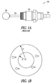
- FIG. 1A is a prior art ball-on-stick particulate matter sensor.
- FIG. 1B shows a simplified model of the operation of the sensor.
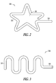
- FIG. 2 is a sensor tip formed by wire bending in two dimensions according to an example embodiment.
- FIG. 3 is a sensor tip formed by wire bending in two dimensions according to an example embodiment.
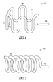
- FIG. 4 is a sensor tip formed by wire bending in three dimensions according to an example embodiment.
- FIG. 5 is a sensor tip formed by wire bending in three dimensions according to an example embodiment.
- FIG. 6 is a sensor tip formed by wire bending in three dimensions according to an example embodiment.
- FIG. 7 is a sensor tip formed by wire bending the sensor end into a helical shape according to an example embodiment.
- FIG. 8 is a system incorporating sensors of an example embodiment.
- FIG. 9 a system incorporating a sensor of an example embodiment.
- FIG. 10 is a method for making the sensor tips according to an example embodiment.
- FIG. 1A is a prior art ball on stick particulate matter sensor.
- the sensor 100 may be a spark-plug-like device having an extended center electrode 120 composed of a stainless steel or other material.
- the electrode 120 and ball 110 may have a thin passivating layer formed on it.
- the sensor 100 may detect charge transients indicative of particulate concentration in the exhaust stream.
- the sensor 100 may be built upon an automotive spark plug 140.
- Ball 110 of sensor 100 may be placed in the path of the exhaust of an engine.
- Ball 110 and electrode 120 may be passivated with a very thin nonconductive coating or layer. This coating or layer accounts for the lack of electrical shorting by the soot layer accumulated by ball 110 and electrode 120 during operation of the engine.
- the passivation material may be composed of silicon nitride (Si 3 N 4 ), ceria and the like.
- the thickness of the passivation layer on ball 110 and electrode 120 may be between 0.001 and 0.100 inch. A nominal thickness may be about 0.01 inch.
- the passivation layer may be achieved with the exposure of the probe to high exhaust gas temperatures or may be coated with such layer via a material added to the engine fuel.
- a ball 110 was placed at the end of a sensor probe similar to electrode 120 to try and induce additional vibration to the sensor 100 and to see if any component of that vibration was due to pressure or velocity variances in the exhaust stream. No additional noise due to vibration was seen, but the signal amplitude increased by about 50% due to the increased surface area. It was determined that the ball-on-stick electrode 110 and 120 structure provides a large surface area at a favored point in the exhaust gas stream. The inventors however have determined that the ball on stick sensor 100 has added costs due to the expense and time of welding ball 110 onto sensor probe 120.
- An embodiment of sensor 100 may be a standard spark plug 140 (such as a Champion TM RJ19LM, though the model is not important) that has the outside electrode removed and has a 4 to 6 inch stainless steel electrode 120 of about 1/8 inch diameter welded to the center electrode 130.
- a stainless steel ball 110 may then be welded to the other end of the electrode 120.
- the extended electrode 129 and ball 110 may be passivated as discussed above with a very thin non-conducting surface layer, so that the ball 110 and electrode 120 will develop an image charge from the exhaust particulates but will not be electrically shorted to the spark plug base 140 or the grounded exhaust pipe.
- the passivating layer may be deposited or grown on the electrode 120 and ball 110.
- FIG. 1B shows a simplified model of the operation of the sensor.
- the sensor operates as a capacitor formed by two concentric spheres.
- the inner sphere has radius a, and the outer sphere has radius b.
- the inner sphere corresponds to the sensor such as ball 110 of FIG. 1 and the outer sphere corresponds to the surrounding exhaust pipe.
- Charges present in the region between the spheres, shown here as individual electron charges, will produce a voltage between the spheres.
- the ball on stick particle sensor 100 of FIG. 1A utilizing the larger mass or ball 110 at the end of electrode 120 has been shown to provide very good results.
- the inventors have determine that the manufacture requirements of welding the ball 110 onto the rod portion of the electrode 120 assembly is complicated.
- Figs. 2-7 show some representative structures that can be used, although other, similar, structures may be apparent to those skilled in the art.
- FIG. 2 is a sensor tip 200 formed by wire bending in two dimensions according to an example embodiment.
- the electrode 220 is bent into a star shape, such that a mass is primarily located at the end 210 of electrode 220.
- a mass is primarily located at the end 210 of electrode 220.
- the star 230 is flattened means of forging, crimping, or other mechanical operation.
- FIG. 3 is a sensor tip 300 formed by wire bending in two dimensions according to an example embodiment.
- the electrode 320 of FIG. 3 is bent into a series of bends much in the form of a series of S's. Thereby as in FIG. 2 the end 310 of electrode 320 having a greater surface area.
- FIG. 4 is a sensor tip 400 formed by wire bending in three dimensions according to an example embodiment.
- the electrode 420 of FIG. 4 is bent into a series of bends as with FIG. 3 in the form of a series of S's.
- a bend of ninety degrees provides a bridge 430 to a second series of S's 440. This shape provides for a greater volume increasing the effect noted with the ball on a stick.
- FIG. 5 is a sensor tip 500 formed by wire bending in three dimensions according to an example embodiment.
- the electrode 520 is bent in a series of S's in one axis and then bent to form a circle to increase the volume at the end 510 of electrode 520.
- FIG. 6 is a sensor tip 600 formed by wire bending in three dimensions according to an example embodiment.
- the electrode 620 is bent in a series of S's in one axis and then bent to form a circle to increase the volume at the end 610 of electrode 620.
- a bend of ninety degrees provides a bridge 630 to a second series of S's 640 that are also formed into a circle.
- FIG. 7 is a sensor tip 700 formed by wire bending the sensor end into a helical shape according to an example embodiment.
- the electrode 720 is bent into a helical shape at the end 710.
- each of the sensor tips illustrated in FIG. 2 through 6 may have increase surface area by flattening the rod 220, 320, 420, 520, 620, and 720 of FIGs. 2-7 respectively, by means of forging, crimping, or other mechanical operation.
- the various sensor tips are thus formed in multiple dimension shapes to increase the surface area of the tip at the end of the electrode.
- FIG. 8 is a system 800 incorporating sensors 810, 820 and 830 of an example embodiment.
- Sensor 810 may be installed in an exhaust pipe 818.
- There may be a stainless steel collar (not shown) welded into the exhaust pipe 818.
- the collar may be fabricated with an oversized threaded access so that the sensor 810 could be easily changed with other sensors 810 having different probe styles.
- Additional sensors 820 may be mounted in the exhaust manifold 822 upstream from turbocharger 819.
- Other sensors 830 may be mounted further down stream, for example about 2 meters, in exhaust pipe 818 from the turbocharger 819.
- the additional sensors 820 and 830 may allow one to examine the effects of the turbocharger 819, such as strong mixing, and residence time on a signal from sensor 810. In the long term sites downstream from turbocharger 819 may be good locations because of the reduced risk of damage to the turbocharger 819 in the event of a sensor 810 failure. Signals 825, indicating an amount of particulate matter in the exhaust 823, on the line from sensor 810 may go to a processor and/or controller 826. Processor 826 may be connected to other particulate sensors 820 and 830, engine sensors, and a fuel injection and intake manifold system 827.
- processor 826 may provide control information signals 829 to the fuel injection amount and timing, EGR percent, valve control, and intake manifold system 827 and the like as desired, so as to cause engine 821 to expel a reduced amount of particulate emissions by adjusting fuel mixture, injection timing, percent EGR, valve control, and so forth.
- exhaust 823 may enter turbocharger 819 and cause a turbine 831 to spin and turn a compressor 832 via a shaft 833.
- Compressor 832 may compress incoming air 828 which goes in a more dense condition
- Sensor 810 may put out a reproducible rms signal representing its image charge monitoring of the exhaust 823, which is correlated to exhaust smoke as characterized by the Bosch smoke number. Sensor 810 generally does not degrade due to soot build-up over a long period of time. Also, sensor 810 does not appear to degrade at various temperatures.
- FIG. 9 a system incorporating a sensor of an example embodiment.
- FIG. 9 is one version of a loop for engine control based on the particulate matter of the exhaust emissions.
- Engine 921 may output an exhaust 923 which is sensed by sensor 910 which in turn may output an image charge signal 925 to processor 926 which may include an amplifier 934, a data extractor 935, and an output signal conditioner 936, among other components of the processor.
- Signal 925 may go to a charge amplifier 934 which may output a real-time signal to a data extraction device 935 which may receive a crankshaft angle determination.
- Components 934, 935 and 936 may have other parameter inputs for improving engine control and performance.
- the output from device 935 may include an electronic indication of the particulate matter concentration or concentrations.
- This signal may go to signal conditioning 936 which may, based on other various inputs of engine data (e.g. timing, temperature, percent EGR, valve position, and other engine information) provide engine control voltage signals 929 (for engine timing, percent EGR, valve control, and the like) to the fuel injection and manifold system 927 of engine 921.
- engine data e.g. timing, temperature, percent EGR, valve position, and other engine information
- engine control voltage signals 929 for engine timing, percent EGR, valve control, and the like
- FIG. 10 is a method for making the sensor tips according to an example embodiment.
- the method 1000 takes an insulated device and forms an elongated electrode and then prepares the electrode to provide for a uniform oxidation layer and to formulate the oxidation layer.
- an insulated device is obtained with an elongated electrode.
- the insulated device may be of a shape similar to a spark plug for a car with the center electrode either elongated from the terminal or soldered onto the center rod of the plug.
- the electrode may be formed following the steps, 1007 through 1070.
- Activity 1007 may be to bend the second end of the center electrode to form a enlarged surface area where the electrode will come in contact with the exhaust.
- the rod is rubbed with a pumice.
- the electrodes are mechanically scrubbed and honed to remove any oxide scale that exists on the rods. This will increase the uniformity of the subsequent etching process.
- Activity 1020 may be to hone the electrode with a wet blast using a mixture of water and silica abrasive at 55 pounds per square inch of pressure. A silica size of 7/0 was found to be suitable. This step cleans the electrodes prior to etching.
- Activity 1030 may be to then wash the electrodes in alconox, or other suitable detergent, to prevent contamination of the etch solution.
- Activity 1040 may be to chemically etch the electrodes in a ferric chloride solution to remove inclusions and micro-roughen the surface for improved oxide adhesion.
- Activity 1050 is to rinse the electrodes and then wash the electrodes in an alconox detergent with ultrasonic vibrations to remove any impurities or debris left on the surface. The electrodes are then thoroughly rinsed to remove any chemical contamination. The electrodes are then dipped in acetone and blown dry with filtered nitrogen to minimize staining.
- Activity 1060 may be to place the electrodes on quartz boats and heat the electrodes to induce oxidation.
- the electrodes are oxidized at elevated temperatures in air to form aluminum oxide (alumina/Al 2 O 3 ) scale.
- the aluminum within the alloy supplies the metal for the alumina formation.
- the alumina provides oxidation protection and electrical insulation.
- One embodiment is to use an oxidation temperature of 1200°C and for 14 hours.
- the alumina oxide will form at lower temperatures and shorter times, but higher temperatures form a more dense coating and longer times form thicker coatings which have superior insulation properties.
- the inventors have noted that these alloys typically have melting points between 1350°C and 1450°C and temperatures above 1200°C typically result in the metal sagging and shape deformation.
- Activity 1070 may be for the electrodes to be rinsed in flowing deionized water for 10 minutes and blown dry with nitrogen.
- super alloys have a native oxide with insulating properties suitable for construction of particulate matter sensor electrodes.
- Super alloys contain aluminum as an alloying addition. When heated in air at high temperatures, the aluminum forms a surface dielectric layer. Since the aluminum has a high diffusivity in the alloys, this surface oxide can be thick. For example, fecralloy, oxidized at 1200 °C for fourteen hours, was found to have a breakdown voltage of 280.3 ⁇ 67.5 volts and an insulation resistance of 41.6 ⁇ 14.9 mega ohms when measured at 850 °C.
- Common iron-based super alloys include fecralloy (Resistalloy International), Kanthal-AF (Kanthal/Sandvik Corp.), Kanthal-A1 (Kanthal/Sandvik Corp.), Aluchrome-O (Thyssen-Krupp VDM), Alkrothal-14 ((Kanthal/Sandvik Corp.), and Haynes 214 (Haynes International).
- a representative nickel-based super alloy is Mar-M-247 (Martin Marietta Materials). The inventors have determined that super alloys oxidized at 1200 °C for fourteen hours were found to have electrical insulating properties at 500 °C. These properties included dielectric breakdown strength greater than 25 volts, and insulation resistance greater than 1 megohm.
- Oxide thickness in this range is sufficient for particulate matter sensor electrodes operating at high temperatures, although oxide thickness of about one micrometer may be suitable for some applications, especially those at lower temperature. Greater oxide thickness in the range of 5-20 micrometers may also be suitable, but oxide thickness greater than about twenty micrometers should be avoided, since the thermal stress at the oxide-alloy interface may promote spallation of the insulating oxide. The maximum oxide thickness for reduction or elimination of oxide spallation will depend on the particular alloy selected, the intended application, and geometry of the electrode.
Landscapes
- Chemical & Material Sciences (AREA)
- Engineering & Computer Science (AREA)
- General Physics & Mathematics (AREA)
- Immunology (AREA)
- Life Sciences & Earth Sciences (AREA)
- Analytical Chemistry (AREA)
- Biochemistry (AREA)
- General Health & Medical Sciences (AREA)
- Physics & Mathematics (AREA)
- Health & Medical Sciences (AREA)
- Pathology (AREA)
- Dispersion Chemistry (AREA)
- Combustion & Propulsion (AREA)
- Mechanical Engineering (AREA)
- General Engineering & Computer Science (AREA)
- Investigating Or Analyzing Materials By The Use Of Electric Means (AREA)
- Ignition Installations For Internal Combustion Engines (AREA)
Abstract
Description
- Many combustion devices produce particulate emissions. For example, diesel engines are increasing in popularity in many kinds of vehicles. In the meantime, environmental regulations relative to particulate emissions are becoming more stringent. Thus, there is need for minimizing emissions from diesel engines and other particulate emitting mechanisms.
- PM emissions contribute to the fine particle burden in the atmosphere. and the EPA has established a light-duty vehicle PM emission standard of 0.08 g/mile and has promulgated a regulation to limit the amount of particular matter with a diameter of 2.5 microns or less (such as the newer 0.1 micron standard being considered). To meet these standards, engine manufacturers have developed low-emission engines. Technological improvements may have reduced mass emissions, but it has been said the newer engines meeting the 1991 emissions limit requirements had dramatically increased numbers and volumes of very small nuclei mode particles when compared to similar engines meeting 1988 emissions limit requirements. These observations suggest that not only accumulation mode size particles, but also nuclei size particles may pose future emission problems.
- Particulate matter (PM) sensors are used in internal combustion engines to determine combustion characteristics, particularly with respect to soot that results from incomplete combustion.
-
FIG. 1A is a prior art ball-on-stick particulate matter sensor. -
FIG. 1B shows a simplified model of the operation of the sensor. -
FIG. 2 is a sensor tip formed by wire bending in two dimensions according to an example embodiment. -
FIG. 3 is a sensor tip formed by wire bending in two dimensions according to an example embodiment. -
FIG. 4 is a sensor tip formed by wire bending in three dimensions according to an example embodiment. -
FIG. 5 is a sensor tip formed by wire bending in three dimensions according to an example embodiment. -
FIG. 6 is a sensor tip formed by wire bending in three dimensions according to an example embodiment. -
FIG. 7 is a sensor tip formed by wire bending the sensor end into a helical shape according to an example embodiment. -
FIG. 8 is a system incorporating sensors of an example embodiment. -
FIG. 9 a system incorporating a sensor of an example embodiment. -
FIG. 10 is a method for making the sensor tips according to an example embodiment. -
FIG. 1A is a prior art ball on stick particulate matter sensor. Thesensor 100 may be a spark-plug-like device having an extendedcenter electrode 120 composed of a stainless steel or other material. Theelectrode 120 andball 110 may have a thin passivating layer formed on it. Thesensor 100 may detect charge transients indicative of particulate concentration in the exhaust stream. Thesensor 100 may be built upon anautomotive spark plug 140.Ball 110 ofsensor 100 may be placed in the path of the exhaust of an engine.Ball 110 andelectrode 120 may be passivated with a very thin nonconductive coating or layer. This coating or layer accounts for the lack of electrical shorting by the soot layer accumulated byball 110 andelectrode 120 during operation of the engine. The passivation material may be composed of silicon nitride (Si3N4), ceria and the like. The thickness of the passivation layer onball 110 andelectrode 120 may be between 0.001 and 0.100 inch. A nominal thickness may be about 0.01 inch. The passivation layer may be achieved with the exposure of the probe to high exhaust gas temperatures or may be coated with such layer via a material added to the engine fuel. - During the testing of a sensor of similar design as
sensor 100 withoutball 110 for vibration noise, aball 110 was placed at the end of a sensor probe similar toelectrode 120 to try and induce additional vibration to thesensor 100 and to see if any component of that vibration was due to pressure or velocity variances in the exhaust stream. No additional noise due to vibration was seen, but the signal amplitude increased by about 50% due to the increased surface area. It was determined that the ball-on-stick electrode stick sensor 100 has added costs due to the expense and time ofwelding ball 110 ontosensor probe 120. - An embodiment of
sensor 100 may be a standard spark plug 140 (such as a Champion™ RJ19LM, though the model is not important) that has the outside electrode removed and has a 4 to 6 inchstainless steel electrode 120 of about 1/8 inch diameter welded to thecenter electrode 130. Astainless steel ball 110 may then be welded to the other end of theelectrode 120. The extended electrode 129 andball 110 may be passivated as discussed above with a very thin non-conducting surface layer, so that theball 110 andelectrode 120 will develop an image charge from the exhaust particulates but will not be electrically shorted to thespark plug base 140 or the grounded exhaust pipe. The passivating layer may be deposited or grown on theelectrode 120 andball 110. -
FIG. 1B shows a simplified model of the operation of the sensor. The sensor operates as a capacitor formed by two concentric spheres. The inner sphere has radius a, and the outer sphere has radius b. The inner sphere corresponds to the sensor such asball 110 ofFIG. 1 and the outer sphere corresponds to the surrounding exhaust pipe. Charges present in the region between the spheres, shown here as individual electron charges, will produce a voltage between the spheres. The capacitance C of the concentric spheres is given as:
- Where ε0 is the permittivity of free space, 8.854 x 10⁻¹² Farad/meter. For b >> a, we may simply the formula, as follows:

- Since the area A of the inner sphere is:

- Then:

- This permits us to generalize the capacitance to the area of the inner sphere, and generalize further to the area of any probe geometry, such that:

- A voltage "E" on a capacitor is given by the equation E = Q/C. Where Q is the capacitor charge. An electron change q is -1.6 x 10⁻¹⁹ Coulombs. This leads to the voltage produced by the presence of a single electron charge in the dielectric volume of the capacitor as given by the equation:

- Estimating for a probe area of about a square inch (5 x 10⁻⁴ m2), E equals 2.3 x 10⁻⁷ volts.
- The ball on
stick particle sensor 100 ofFIG. 1A utilizing the larger mass orball 110 at the end ofelectrode 120 has been shown to provide very good results. However, the inventors have determine that the manufacture requirements of welding theball 110 onto the rod portion of theelectrode 120 assembly is complicated. The inventors propose, instead, to shape the end of the rod into a suitably large area before oxidation to obtain the dielectric layer.Figs. 2-7 show some representative structures that can be used, although other, similar, structures may be apparent to those skilled in the art. -
FIG. 2 is asensor tip 200 formed by wire bending in two dimensions according to an example embodiment. Theelectrode 220 is bent into a star shape, such that a mass is primarily located at theend 210 ofelectrode 220. Thereby obtaining the advantage, greater area of theball 110 ofFIG. 1 , without the complicated step of welding theball 110 onto theelectrode 120. To increase the surface area ofstar 230 thestar 230 is flattened means of forging, crimping, or other mechanical operation. -
FIG. 3 is asensor tip 300 formed by wire bending in two dimensions according to an example embodiment. Theelectrode 320 ofFIG. 3 is bent into a series of bends much in the form of a series of S's. Thereby as inFIG. 2 theend 310 ofelectrode 320 having a greater surface area. -
FIG. 4 is asensor tip 400 formed by wire bending in three dimensions according to an example embodiment. Theelectrode 420 ofFIG. 4 is bent into a series of bends as withFIG. 3 in the form of a series of S's. At theend 410, a bend of ninety degrees provides abridge 430 to a second series of S's 440. This shape provides for a greater volume increasing the effect noted with the ball on a stick. -
FIG. 5 is asensor tip 500 formed by wire bending in three dimensions according to an example embodiment. Theelectrode 520 is bent in a series of S's in one axis and then bent to form a circle to increase the volume at theend 510 ofelectrode 520. -
FIG. 6 is asensor tip 600 formed by wire bending in three dimensions according to an example embodiment. Theelectrode 620 is bent in a series of S's in one axis and then bent to form a circle to increase the volume at theend 610 ofelectrode 620. At the end 610 a bend of ninety degrees provides abridge 630 to a second series of S's 640 that are also formed into a circle. -
FIG. 7 is asensor tip 700 formed by wire bending the sensor end into a helical shape according to an example embodiment. Theelectrode 720 is bent into a helical shape at theend 710. In addition each of the sensor tips illustrated inFIG. 2 through 6 may have increase surface area by flattening therod FIGs. 2-7 respectively, by means of forging, crimping, or other mechanical operation. The various sensor tips are thus formed in multiple dimension shapes to increase the surface area of the tip at the end of the electrode. -
FIG. 8 is asystem 800 incorporatingsensors Sensor 810 may be installed in anexhaust pipe 818. There may be a stainless steel collar (not shown) welded into theexhaust pipe 818. The collar may be fabricated with an oversized threaded access so that thesensor 810 could be easily changed withother sensors 810 having different probe styles.Additional sensors 820 may be mounted in theexhaust manifold 822 upstream fromturbocharger 819.Other sensors 830 may be mounted further down stream, for example about 2 meters, inexhaust pipe 818 from theturbocharger 819. - The
additional sensors turbocharger 819, such as strong mixing, and residence time on a signal fromsensor 810. In the long term sites downstream fromturbocharger 819 may be good locations because of the reduced risk of damage to theturbocharger 819 in the event of asensor 810 failure.Signals 825, indicating an amount of particulate matter in theexhaust 823, on the line fromsensor 810 may go to a processor and/orcontroller 826.Processor 826 may be connected to otherparticulate sensors intake manifold system 827. Based onsignals 825 fromsensor 810 and possibly fromsensors system 827 andengine 821, for sensing some or all of, but not limited to, the following engine parameters (vialine 837 to processor 826) such as fuel flow, EGR (exhaust gas recirculation), injection timing, needle lift, crankshaft angle, cylinder pressure, valve position and lift, manifold vacuum, fuel/air mixture, the intake properties ofair 828 and other information from or aboutengine 821,processor 826 may provide control information signals 829 to the fuel injection amount and timing, EGR percent, valve control, andintake manifold system 827 and the like as desired, so as to causeengine 821 to expel a reduced amount of particulate emissions by adjusting fuel mixture, injection timing, percent EGR, valve control, and so forth. Incidentally,exhaust 823 may enterturbocharger 819 and cause aturbine 831 to spin and turn acompressor 832 via ashaft 833.Compressor 832 may compressincoming air 828 which goes in a more dense condition tosystem 827. - Initial concerns relative to
sensor 810 were possible fouling by excessive soot and very high temperatures. However, operation ofsensor 810 in an exhaust system has been reliable in view of operation ofengine 821 under very heavy loads causing the observedexhaust 823 temperature to reach at least 670 degrees C (1238 degrees F) and resulting in a Bosch smoke number ofexhaust 823 to be at least 5. The latter number may correspond to a particle mass concentration of 350 mg/m3. -
Sensor 810 may put out a reproducible rms signal representing its image charge monitoring of theexhaust 823, which is correlated to exhaust smoke as characterized by the Bosch smoke number.Sensor 810 generally does not degrade due to soot build-up over a long period of time. Also,sensor 810 does not appear to degrade at various temperatures. -
FIG. 9 a system incorporating a sensor of an example embodiment.FIG. 9 is one version of a loop for engine control based on the particulate matter of the exhaust emissions.Engine 921 may output anexhaust 923 which is sensed bysensor 910 which in turn may output animage charge signal 925 toprocessor 926 which may include anamplifier 934, adata extractor 935, and anoutput signal conditioner 936, among other components of the processor.Signal 925 may go to acharge amplifier 934 which may output a real-time signal to adata extraction device 935 which may receive a crankshaft angle determination.Components device 935 may include an electronic indication of the particulate matter concentration or concentrations. This signal may go tosignal conditioning 936 which may, based on other various inputs of engine data (e.g. timing, temperature, percent EGR, valve position, and other engine information) provide engine control voltage signals 929 (for engine timing, percent EGR, valve control, and the like) to the fuel injection andmanifold system 927 ofengine 921. -
FIG. 10 is a method for making the sensor tips according to an example embodiment. Themethod 1000 takes an insulated device and forms an elongated electrode and then prepares the electrode to provide for a uniform oxidation layer and to formulate the oxidation layer. At 1003, an insulated device is obtained with an elongated electrode. The insulated device may be of a shape similar to a spark plug for a car with the center electrode either elongated from the terminal or soldered onto the center rod of the plug. As an alternative, rather than form the electrode while it is attached to the insulated device, the electrode may be formed following the steps, 1007 through 1070.Activity 1007 may be to bend the second end of the center electrode to form a enlarged surface area where the electrode will come in contact with the exhaust. - At 1010 once the rod or sensor has been bent into the desired configuration and the rod has been flattened, the rod is rubbed with a pumice. The electrodes are mechanically scrubbed and honed to remove any oxide scale that exists on the rods. This will increase the uniformity of the subsequent etching process.
-
Activity 1020 may be to hone the electrode with a wet blast using a mixture of water and silica abrasive at 55 pounds per square inch of pressure. A silica size of 7/0 was found to be suitable. This step cleans the electrodes prior to etching.Activity 1030 may be to then wash the electrodes in alconox, or other suitable detergent, to prevent contamination of the etch solution.Activity 1040 may be to chemically etch the electrodes in a ferric chloride solution to remove inclusions and micro-roughen the surface for improved oxide adhesion.Activity 1050 is to rinse the electrodes and then wash the electrodes in an alconox detergent with ultrasonic vibrations to remove any impurities or debris left on the surface. The electrodes are then thoroughly rinsed to remove any chemical contamination. The electrodes are then dipped in acetone and blown dry with filtered nitrogen to minimize staining. -
Activity 1060 may be to place the electrodes on quartz boats and heat the electrodes to induce oxidation. The electrodes are oxidized at elevated temperatures in air to form aluminum oxide (alumina/Al2O3) scale. The aluminum within the alloy supplies the metal for the alumina formation. The alumina provides oxidation protection and electrical insulation. One embodiment is to use an oxidation temperature of 1200°C and for 14 hours. The alumina oxide will form at lower temperatures and shorter times, but higher temperatures form a more dense coating and longer times form thicker coatings which have superior insulation properties. The inventors have noted that these alloys typically have melting points between 1350°C and 1450°C and temperatures above 1200°C typically result in the metal sagging and shape deformation. -
Activity 1070 may be for the electrodes to be rinsed in flowing deionized water for 10 minutes and blown dry with nitrogen. - The inventors have shown that super alloys have a native oxide with insulating properties suitable for construction of particulate matter sensor electrodes. Super alloys contain aluminum as an alloying addition. When heated in air at high temperatures, the aluminum forms a surface dielectric layer. Since the aluminum has a high diffusivity in the alloys, this surface oxide can be thick. For example, fecralloy, oxidized at 1200 °C for fourteen hours, was found to have a breakdown voltage of 280.3 ± 67.5 volts and an insulation resistance of 41.6 ± 14.9 mega ohms when measured at 850 °C.
- Common iron-based super alloys include fecralloy (Resistalloy International), Kanthal-AF (Kanthal/Sandvik Corp.), Kanthal-A1 (Kanthal/Sandvik Corp.), Aluchrome-O (Thyssen-Krupp VDM), Alkrothal-14 ((Kanthal/Sandvik Corp.), and Haynes 214 (Haynes International). A representative nickel-based super alloy is Mar-M-247 (Martin Marietta Materials). The inventors have determined that super alloys oxidized at 1200 °C for fourteen hours were found to have electrical insulating properties at 500 °C. These properties included dielectric breakdown strength greater than 25 volts, and insulation resistance greater than 1 megohm. Microscopy of cross-sections of oxidized alloys gave the following oxide thickness values for oxidation under this condition. Table 1 illustrates the thickness of the oxides for various alloy types.
TABLE 1 Alloy Type Oxide Thickness (micrometer) FeCrAlloy 6.35 ± 2.22 Kanthal-AF 4.80 ± 1.43 Kanthal-A1 5.45 ± 2.18 Aluchrome-O 4.56 ± 1.64 Alkrothal-720 9.26 ± 3.21 Haynes 214 3.51 ± 1.01 - Oxide thickness in this range is sufficient for particulate matter sensor electrodes operating at high temperatures, although oxide thickness of about one micrometer may be suitable for some applications, especially those at lower temperature. Greater oxide thickness in the range of 5-20 micrometers may also be suitable, but oxide thickness greater than about twenty micrometers should be avoided, since the thermal stress at the oxide-alloy interface may promote spallation of the insulating oxide. The maximum oxide thickness for reduction or elimination of oxide spallation will depend on the particular alloy selected, the intended application, and geometry of the electrode.
- The Abstract of the Disclosure is provided to comply with 37 C.F.R. §1.72(b) requiring an abstract that will allow the reader to quickly ascertain the nature of the technical disclosure. It is submitted with the understanding that it will not be used to interpret or limit the scope or meaning of the claims. The above description and figures illustrate embodiments of the invention to enable those skilled in the art to practice the embodiments of the invention. Thus the following claims are hereby incorporated into the Detailed Description, with each claim standing on its own as a separate embodiment.
Claims (10)
- A particulate matter detector comprising:an insulated device (810, 820, 830, 910); anda center electrode (200, 300, 400, 500, 600, 700) having a first end (220, 320, 420, 520, 620, 720) and a second end (210, 310, 410, 510, 610, 710) wherein first end of the center electrode passes through the insulated device and the second end of the electrode is formed to provide an increased surface area.
- The detector of claim 1, wherein the second end of the electrode is formed into a star shape, an s shape, an s shape having a bend to a second series of bends in an s shape, or a helix.
- The detector of claims 1 or 2, wherein the second end of the electrode is flattened.
- The detector of claims 1, 2 or 3 wherein:the center electrode has a length between 0.25 inch and 12 inches; andthe center electrode has a thickness between 1/32 inch and 3/8 inch.
- The detector of claims 1, 2, 3, or 4 wherein:the insulated device has a terminal connected to the first end of the center electrode; andthe terminal is connected to an amplifier having an output that may indicate a particulate concentration in a vicinity of the second end of the electrode.
- The detector of claim 5, wherein the second end of the center electrode is situated in a portion of a combustion mechanism.
- The detector of claim 1 wherein the electrode is formed of one of an iron-chrome alloy, a Kanthal-AF, a Kanthal- AL, an Aluchrome-O, an Alkrothal-720, Haynes 214 or an aluminum containing alloy.
- A method of making a particulate detector, comprising:obtaining an insulated device having an elongated center electrode (1003), a first end of the center electrode coupled to a terminal; andbending the second end of the center electrode to form a greater area at the second end of the center electrode (1007).
- The method of claim 8, comprising:heating the center electrode to induce oxidation (1060).
- The method of claim 9, comprising:rubbing the electrode with a pumice (1010);honing the electrode with a mixture of silica abrasive and water (1020); andwashing the electrode in a detergent (1030).
Applications Claiming Priority (1)
| Application Number | Priority Date | Filing Date | Title |
|---|---|---|---|
| US12/020,950 US7966862B2 (en) | 2008-01-28 | 2008-01-28 | Electrode structure for particulate matter sensor |
Publications (3)
| Publication Number | Publication Date |
|---|---|
| EP2090879A2 true EP2090879A2 (en) | 2009-08-19 |
| EP2090879A3 EP2090879A3 (en) | 2013-10-16 |
| EP2090879B1 EP2090879B1 (en) | 2017-08-02 |
Family
ID=40428244
Family Applications (1)
| Application Number | Title | Priority Date | Filing Date |
|---|---|---|---|
| EP09151040.4A Active EP2090879B1 (en) | 2008-01-28 | 2009-01-21 | Electrode structure for particulate matter sensor |
Country Status (2)
| Country | Link |
|---|---|
| US (1) | US7966862B2 (en) |
| EP (1) | EP2090879B1 (en) |
Cited By (1)
| Publication number | Priority date | Publication date | Assignee | Title |
|---|---|---|---|---|
| EP3187863A4 (en) * | 2014-08-29 | 2018-05-02 | Kyocera Corporation | Sensor substrate, sensor substrate with lead, and sensor device |
Families Citing this family (14)
| Publication number | Priority date | Publication date | Assignee | Title |
|---|---|---|---|---|
| US7928634B2 (en) * | 2008-04-22 | 2011-04-19 | Honeywell International Inc. | System and method for providing a piezoelectric electromagnetic hybrid vibrating energy harvester |
| WO2009140677A2 (en) * | 2008-05-16 | 2009-11-19 | Honeywell International Inc. | Particulate matter sensor |
| US8047054B2 (en) * | 2008-07-24 | 2011-11-01 | Fram Group Ip Llc | Particulate matter sensor |
| DE102010029575A1 (en) | 2010-06-01 | 2011-12-01 | Robert Bosch Gmbh | Method and particle sensor for detecting particles in an exhaust gas stream |
| DE102010038153B3 (en) * | 2010-10-13 | 2012-03-08 | Ford Global Technologies, Llc. | Particle sensor for protection of components of exhaust system of turbocharged engine, is arranged at lower pressure side of turbocharger, and outputs signal for switching off exhaust gas recirculation |
| KR101934887B1 (en) * | 2011-06-22 | 2019-01-04 | 코닌클리케 필립스 엔.브이. | A cleaning device for cleaning the air-ionizing part of an electrode |
| KR101305198B1 (en) * | 2011-12-09 | 2013-09-26 | 현대자동차주식회사 | Particulate matters sensor unit |
| US8823401B2 (en) * | 2012-03-30 | 2014-09-02 | Delphi Technologies, Inc. | Particulate matter sensor with two pairs of sensing electrodes and methods of using same |
| JP6228018B2 (en) | 2014-01-10 | 2017-11-08 | 株式会社Soken | Particulate matter detection element, particulate matter detection sensor, and method for manufacturing particulate matter detection element |
| JP6654350B2 (en) * | 2015-02-18 | 2020-02-26 | 三菱航空機株式会社 | Piping structure and aircraft |
| KR20160149898A (en) | 2015-06-19 | 2016-12-28 | 현대자동차주식회사 | Particulate matter sensor |
| JP6918806B2 (en) * | 2016-01-08 | 2021-08-11 | ティーエスアイ インコーポレイテッド | Wearable mask fit monitor |
| US10018098B2 (en) | 2016-04-14 | 2018-07-10 | Ford Global Technologies, Llc | Method and system for exhaust particulate matter sensing |
| CN112179284B (en) * | 2020-09-25 | 2021-10-15 | 贵州百事通建筑安装工程有限公司 | Steel structure welding ball joint and bolt ball joint bearing capacity testing method |
Family Cites Families (45)
| Publication number | Priority date | Publication date | Assignee | Title |
|---|---|---|---|---|
| US3869703A (en) * | 1970-03-16 | 1975-03-04 | Philips Corp | Semiconductor device having an improved supply lead support |
| US4021326A (en) | 1972-06-02 | 1977-05-03 | Robert Bosch G.M.B.H. | Electro-chemical sensor |
| DE2700807A1 (en) | 1977-01-11 | 1978-07-13 | Bosch Gmbh Robert | FIXED ELECTROLYTE TUBE FOR A SENSOR FOR DETERMINING THE OXYGEN CONTENT IN EXHAUST GASES AND A PROCESS FOR THE PRODUCTION OF THIS |
| DE2836002C2 (en) | 1978-08-17 | 1986-09-11 | Robert Bosch Gmbh, 7000 Stuttgart | Sensor for monitoring the absence of soot in exhaust gases |
| DE2913866C2 (en) | 1979-04-06 | 1987-03-12 | Robert Bosch Gmbh, 7000 Stuttgart | Sensor for the determination of components in flowing gases |
| DE2942494A1 (en) | 1979-10-20 | 1981-04-30 | Bosch Gmbh Robert | HEATABLE SENSOR FOR COMPONENTS OF GASES, ESPECIALLY IN EXHAUST GASES FROM COMBUSTION ENGINES |
| US4656832A (en) | 1982-09-30 | 1987-04-14 | Nippondenso Co., Ltd. | Detector for particulate density and filter with detector for particulate density |
| US4485794A (en) | 1982-10-04 | 1984-12-04 | United Technologies Diesel Systems, Inc. | Method and apparatus for controlling diesel engine exhaust gas recirculation partly as a function of exhaust particulate level |
| US5271821A (en) | 1988-03-03 | 1993-12-21 | Ngk Insulators, Ltd. | Oxygen sensor and method of producing the same |
| FR2640955B1 (en) * | 1988-12-26 | 1991-11-29 | Taillet Joseph | |
| DE69026353T2 (en) * | 1989-12-19 | 1996-11-14 | Matsushita Electric Ind Co Ltd | Field emission device and method of manufacturing the same |
| US5076237A (en) | 1990-01-11 | 1991-12-31 | Barrack Technology Limited | Means and method for measuring and controlling smoke from an internal combustion engine |
| KR950004615B1 (en) | 1990-09-27 | 1995-05-03 | 미쓰비시덴키 가부시키가이샤 | Spark Plugs for Internal Combustion Engines |
| GB2277154B (en) | 1993-04-06 | 1997-06-25 | Pollution Control & Measuremen | Method and apparatus for detecting particles in a flow |
| WO1995018777A1 (en) | 1994-01-05 | 1995-07-13 | Roth-Technik Gmbh & Co. Forschung Für Automobil- Und Umwelttechnik | Electrically conductive connection |
| US5898257A (en) | 1995-08-25 | 1999-04-27 | Sequerra; Richard Isaac | Combustion initiators employing reduced work function stainless steel electrodes |
| DE19536705A1 (en) * | 1995-09-30 | 1997-04-03 | Guenther Prof Dr Ing Hauser | Method for measuring particles in gas flow e.g. vehicle exhaust |
| JP3333678B2 (en) | 1996-01-05 | 2002-10-15 | 株式会社日立製作所 | Gas component sensor and catalyst diagnostic device |
| US5681986A (en) | 1996-05-07 | 1997-10-28 | Auburn International, Inc. | Acoustic sensing |
| JP3813708B2 (en) | 1996-09-12 | 2006-08-23 | 日本特殊陶業株式会社 | Manufacturing method of spark plug |
| SE513432C2 (en) | 1997-12-01 | 2000-09-11 | Volvo Ab | A method for measuring the particle content of the exhaust gases of an internal combustion engine |
| US6583539B1 (en) | 1999-08-23 | 2003-06-24 | Antonio Lopez Zamora | Spark plug with center electrode and surrounding ground electrode |
| JP2001073918A (en) | 1999-09-02 | 2001-03-21 | Ngk Spark Plug Co Ltd | Smoldering detection method |
| DE19959871A1 (en) | 1999-12-10 | 2001-06-28 | Heraeus Electro Nite Int | Sensor and method for determining soot concentrations |
| DE19959870A1 (en) | 1999-12-10 | 2001-06-21 | Heraeus Electro Nite Int | Measuring arrangement and method for monitoring the functionality of a soot filter |
| DE10052005C2 (en) | 2000-10-20 | 2002-11-21 | Bosch Gmbh Robert | Sensor for gases |
| US6601464B1 (en) | 2000-10-20 | 2003-08-05 | John P. Downing, Jr. | Particle momentum sensor |
| DE10124907A1 (en) | 2001-05-22 | 2002-11-28 | Bosch Gmbh Robert | Electrode assembly for monitoring soot in the exhaust channel of an IC engine, or a oil heating system, has an insulation holder body with a working electrode, and a test electrode to monitor the body insulation resistance |
| JP2003107033A (en) | 2001-07-27 | 2003-04-09 | Denso Corp | Gas sensor |
| US7010356B2 (en) * | 2001-10-31 | 2006-03-07 | London Health Sciences Centre Research Inc. | Multichannel electrode and methods of using same |
| US6639671B1 (en) * | 2002-03-01 | 2003-10-28 | Msp Corporation | Wide-range particle counter |
| US6634210B1 (en) | 2002-04-17 | 2003-10-21 | Delphi Technologies, Inc. | Particulate sensor system |
| US7275415B2 (en) * | 2003-12-31 | 2007-10-02 | Honeywell International Inc. | Particulate-based flow sensor |
| US6971258B2 (en) * | 2003-12-31 | 2005-12-06 | Honeywell International Inc. | Particulate matter sensor |
| US7328577B2 (en) | 2004-12-29 | 2008-02-12 | Honeywell International Inc. | Multivariable control for an engine |
| US7389773B2 (en) | 2005-08-18 | 2008-06-24 | Honeywell International Inc. | Emissions sensors for fuel control in engines |
| US7155334B1 (en) | 2005-09-29 | 2006-12-26 | Honeywell International Inc. | Use of sensors in a state observer for a diesel engine |
| US7765792B2 (en) * | 2005-10-21 | 2010-08-03 | Honeywell International Inc. | System for particulate matter sensor signal processing |
| US7628007B2 (en) | 2005-12-21 | 2009-12-08 | Honeywell International Inc. | Onboard diagnostics for anomalous cylinder behavior |
| US7447587B2 (en) | 2005-12-21 | 2008-11-04 | Honeywell International Inc. | Cylinder to cylinder variation control |
| US20080265870A1 (en) | 2007-04-27 | 2008-10-30 | Nair Balakrishnan G | Particulate Matter Sensor |
| US7564043B2 (en) * | 2007-05-24 | 2009-07-21 | Hamamatsu Photonics K.K. | MCP unit, MCP detector and time of flight mass spectrometer |
| US8080427B2 (en) | 2007-07-31 | 2011-12-20 | Caterpillar Inc. | Particle sensor |
| US20090056416A1 (en) | 2007-08-30 | 2009-03-05 | Nair Balakrishnan G | Ceramic Particulate Matter Sensor With Low Electrical Leakage |
| US7900500B2 (en) | 2007-11-05 | 2011-03-08 | Honeywell International Inc. | Particulate matter sensor electrodes with embedded self-calibrator, and methods using same |
-
2008
- 2008-01-28 US US12/020,950 patent/US7966862B2/en active Active
-
2009
- 2009-01-21 EP EP09151040.4A patent/EP2090879B1/en active Active
Non-Patent Citations (1)
| Title |
|---|
| None |
Cited By (2)
| Publication number | Priority date | Publication date | Assignee | Title |
|---|---|---|---|---|
| EP3187863A4 (en) * | 2014-08-29 | 2018-05-02 | Kyocera Corporation | Sensor substrate, sensor substrate with lead, and sensor device |
| US10408776B2 (en) | 2014-08-29 | 2019-09-10 | Kyocera Corporation | Sensor board, lead-bearing sensor board, and sensor device |
Also Published As
| Publication number | Publication date |
|---|---|
| US7966862B2 (en) | 2011-06-28 |
| EP2090879A3 (en) | 2013-10-16 |
| EP2090879B1 (en) | 2017-08-02 |
| US20090188300A1 (en) | 2009-07-30 |
Similar Documents
| Publication | Publication Date | Title |
|---|---|---|
| EP2090879B1 (en) | Electrode structure for particulate matter sensor | |
| US6971258B2 (en) | Particulate matter sensor | |
| JP6600704B2 (en) | 煤 Sensor system | |
| US8091408B2 (en) | Procedure for operating a collecting particle sensor and device for implementing this procedure | |
| US8165786B2 (en) | System for particulate matter sensor signal processing | |
| CN105723205B (en) | Method and apparatus for operating a particle sensor | |
| US9377425B2 (en) | Method and device for regenerating a particle sensor | |
| Ntziachristos et al. | Application of the Pegasor particle sensor for the measurement of mass and particle number emissions | |
| US20070137177A1 (en) | Onboard Diagnostics for Anomalous Cylinder Behavior | |
| US20130090866A1 (en) | Diagnostic method for a soot sensor | |
| US20090051376A1 (en) | Method for influencing soot deposits on sensors | |
| US20110314899A1 (en) | Method and device for operating a particle sensor | |
| US20110156727A1 (en) | Soot Sensor | |
| EP2840388A1 (en) | Gas sensor | |
| CN107300518B (en) | Method and system for exhaust particulate matter sensing | |
| CN105298608A (en) | Diagnostic method and device for particulate matter discharging for novel external automotive diesel engine | |
| US20200284711A1 (en) | Electrostatic Soot Sensor | |
| US20080034839A1 (en) | Method and Device for Monitoring Particle Concentration in Gas Stream | |
| DE19806110A1 (en) | Method for determining the exhaust gas temperature and the air / fuel ratio lambda and sensor arrangement for carrying out the method | |
| Hoepfner et al. | PM sensor based on-board diagnosis of particulate filter efficiency | |
| US6637254B2 (en) | Sensor element having a protective device | |
| US11422081B2 (en) | Sensor for use in an exhaust gas stream of an internal combustion engine | |
| Sappok et al. | Direct measurement of aftertreatment system stored water levels for improved dew point management using radio frequency sensing | |
| US20230332982A1 (en) | Method for monitoring a sensor arranged in an exhaust gas region of an internal combustion engine | |
| KR102443748B1 (en) | A method of operating a sensor element for detecting particles of a measuring gas in a measuring gas chamber |
Legal Events
| Date | Code | Title | Description |
|---|---|---|---|
| PUAI | Public reference made under article 153(3) epc to a published international application that has entered the european phase |
Free format text: ORIGINAL CODE: 0009012 |
|
| 17P | Request for examination filed |
Effective date: 20090121 |
|
| AK | Designated contracting states |
Kind code of ref document: A2 Designated state(s): AT BE BG CH CY CZ DE DK EE ES FI FR GB GR HR HU IE IS IT LI LT LU LV MC MK MT NL NO PL PT RO SE SI SK TR |
|
| AX | Request for extension of the european patent |
Extension state: AL BA RS |
|
| PUAL | Search report despatched |
Free format text: ORIGINAL CODE: 0009013 |
|
| AK | Designated contracting states |
Kind code of ref document: A3 Designated state(s): AT BE BG CH CY CZ DE DK EE ES FI FR GB GR HR HU IE IS IT LI LT LU LV MC MK MT NL NO PL PT RO SE SI SK TR |
|
| AX | Request for extension of the european patent |
Extension state: AL BA RS |
|
| RIC1 | Information provided on ipc code assigned before grant |
Ipc: G01N 15/06 20060101AFI20130906BHEP |
|
| AKX | Designation fees paid |
Designated state(s): DE |
|
| 17Q | First examination report despatched |
Effective date: 20141218 |
|
| RAP1 | Party data changed (applicant data changed or rights of an application transferred) |
Owner name: HONEYWELL INTERNATIONAL INC. |
|
| REG | Reference to a national code |
Ref country code: DE Ref legal event code: R079 Ref document number: 602009047446 Country of ref document: DE Free format text: PREVIOUS MAIN CLASS: G01N0015060000 Ipc: F02D0041140000 |
|
| GRAP | Despatch of communication of intention to grant a patent |
Free format text: ORIGINAL CODE: EPIDOSNIGR1 |
|
| RIC1 | Information provided on ipc code assigned before grant |
Ipc: F02D 41/14 20060101AFI20170214BHEP Ipc: G01N 15/06 20060101ALI20170214BHEP Ipc: F01N 9/00 20060101ALN20170214BHEP |
|
| INTG | Intention to grant announced |
Effective date: 20170317 |
|
| GRAS | Grant fee paid |
Free format text: ORIGINAL CODE: EPIDOSNIGR3 |
|
| GRAA | (expected) grant |
Free format text: ORIGINAL CODE: 0009210 |
|
| AK | Designated contracting states |
Kind code of ref document: B1 Designated state(s): DE |
|
| REG | Reference to a national code |
Ref country code: DE Ref legal event code: R096 Ref document number: 602009047446 Country of ref document: DE |
|
| REG | Reference to a national code |
Ref country code: DE Ref legal event code: R097 Ref document number: 602009047446 Country of ref document: DE |
|
| PLBE | No opposition filed within time limit |
Free format text: ORIGINAL CODE: 0009261 |
|
| STAA | Information on the status of an ep patent application or granted ep patent |
Free format text: STATUS: NO OPPOSITION FILED WITHIN TIME LIMIT |
|
| 26N | No opposition filed |
Effective date: 20180503 |
|
| PGFP | Annual fee paid to national office [announced via postgrant information from national office to epo] |
Ref country code: DE Payment date: 20260127 Year of fee payment: 18 |